1
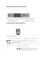
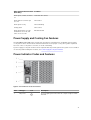
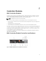
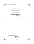
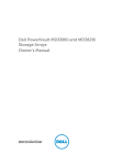
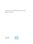
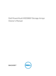
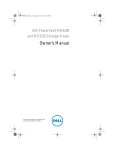
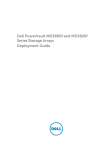
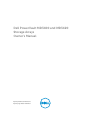
Dell PowerVault MD3400 and MD3420
Storage Arrays
Owner's Manual
Regulatory Model: E03J and E04J Series
Regulatory Type: E03J001 and E04J001
Notes, Cautions, and Warnings
NOTE: A NOTE indicates important information that helps you make better use of your computer.
CAUTION: A CAUTION indicates either potential damage to hardware or loss of data and tells you
how to avoid the problem.
WARNING: A WARNING indicates a potential for property damage, personal injury, or death.
Copyright © 2014 Dell Inc. All rights reserved. This product is protected by U.S. and international copyright and
intellectual property laws. Dell™ and the Dell logo are trademarks of Dell Inc. in the United States and/or other
jurisdictions. All other marks and names mentioned herein may be trademarks of their respective companies.
2014 - 02
Rev. A00
Contents
1 About Your System....................................................................................................7
Introduction........................................................................................................................................... 7
Front-Panel Features and Indicators.................................................................................................... 7
Back-Panel Features and Indicators................................................................................................... 10
Physical-Drive Indicator Patterns....................................................................................................... 10
Power Supply and Cooling Fan Features............................................................................................ 11
Power Indicator Codes and Features..................................................................................................11
Related Documentation...................................................................................................................... 12
2 Controller Modules................................................................................................ 13
RAID Controller Modules.................................................................................................................... 13
RAID Controller Module Connectors and Features........................................................................... 13
RAID Controller Module—Additional Features...................................................................................14
Battery Backup Unit....................................................................................................................... 14
Storage Array Thermal Shutdown................................................................................................. 15
System Password Reset................................................................................................................. 15
Cache Functions and Features............................................................................................................15
Cache Mirroring............................................................................................................................. 15
Write-Back Cache..........................................................................................................................15
Write-Through Cache................................................................................................................... 15
3 Installing Array Components............................................................................... 17
Recommended Tools.......................................................................................................................... 17
Front Bezel (Optional)..........................................................................................................................17
Removing the Front Bezel............................................................................................................. 17
Installing the Front Bezel............................................................................................................... 17
Physical Drives..................................................................................................................................... 18
SAFETY Models AMT E03J and E04J............................................................................................ 18
Removing a 2.5 Inch Physical-Drive Blank................................................................................... 18
Installing a 2.5 Inch Physical-Drive Blank..................................................................................... 18
Removing a 3.5 Inch Physical-Drive Blank................................................................................... 18
Installing a 3.5 Inch Physical-Drive Blank..................................................................................... 19
Removing a Hot-Swap Physical Drive.......................................................................................... 19
Installing a Hot-Swap Physical Drive............................................................................................20
Removing a Physical Drive From a Physical-Drive Carrier...........................................................21
Installing a Physical Drive Into a Physical-Drive Carrier.............................................................. 22
RAID Controller Module .....................................................................................................................22
Removing a RAID Controller Module Blank................................................................................. 23
Installing a RAID Controller Module Blank................................................................................... 23
Removing a RAID Controller Module .......................................................................................... 23
Installing a RAID Controller Module ............................................................................................ 24
Opening the RAID Controller Module ......................................................................................... 25
Closing the RAID Controller Module............................................................................................ 25
RAID Controller Module Backup Battery Unit ...................................................................................26
Removing the RAID Controller Module Backup Battery Unit .....................................................26
Installing the RAID Controller Module Backup Battery Unit........................................................26
Power Supply/Cooling Fan Module....................................................................................................27
Removing a Power Supply/Cooling Fan Module......................................................................... 27
Installing a Power Supply/Cooling Fan Module...........................................................................28
Control Panel...................................................................................................................................... 29
Removing the Control Panel........................................................................................................ 29
Installing the Control Panel.......................................................................................................... 30
Backplane.............................................................................................................................................31
Removing the Backplane...............................................................................................................31
Installing the Backplane................................................................................................................ 33
4 Troubleshooting Your System............................................................................ 35
Safety First—For You and Your System.............................................................................................. 35
Troubleshooting Storage Array Startup Failure..................................................................................35
Troubleshooting Loss of Communication......................................................................................... 35
Troubleshooting External Connections............................................................................................. 35
Troubleshooting Power Supply/Cooling Fan Modules..................................................................... 36
Troubleshooting Array Cooling Problems......................................................................................... 36
Troubleshooting Expansion Enclosure Management Modules.........................................................37
If EMM Status LED is Blinking Amber (5 Times per Sequence) ................................................... 37
If the EMM Status LED is Solid or Blinking Amber (2 or 4 Times per Sequence)........................ 37
If the Link Status LEDs are not Green........................................................................................... 37
Troubleshooting RAID Controller Modules........................................................................................37
If the Array Status LED is Solid or Blinking Amber....................................................................... 38
If the Link Status LEDs are not Green...........................................................................................38
Troubleshooting Physical Disks..........................................................................................................38
Troubleshooting Array and Expansion Enclosure Connections....................................................... 39
Troubleshooting a Wet System.......................................................................................................... 39
Troubleshooting a Damaged System.................................................................................................40
Controller Failure Conditions............................................................................................................. 40
Critical Conditions........................................................................................................................ 40
Noncritical Conditions.................................................................................................................. 41
Invalid Storage Array......................................................................................................................41
ECC Errors......................................................................................................................................41
PCI Errors....................................................................................................................................... 41
5 Technical Specifications....................................................................................... 43
6 Getting Help.............................................................................................................47
Locating Your System Service Tag..................................................................................................... 47
Contacting Dell................................................................................................................................... 47
Documentation Feedback.................................................................................................................. 47
6
About Your System
1
Introduction
The MD3400 and MD3420 Series storage array is designed for high availability, offering redundant access
to data storage. Its features support both single and dual RAID controller configurations.
The Dell PowerVault MD3400 and MD 3420 Series storage array provides 12 Gbps SAS connectivity to the
host server. It enables access for up to eight non-redundant servers or four redundant servers.
The MD3400 and MD3420 Series storage array includes a number of components. These components
are:
•
RAID controller module(s)
•
PSU/fan modules
•
Disk drives (also called physical disks/hard drives in this document)
•
A front bezel (optional)
•
A system enclosure, into which the other components are plugged
Front-Panel Features and Indicators
Figure 1. Front-Panel Features and Indicators—Dell PowerVault MD3400
7
Figure 2. Front-Panel Features and Indicators—Dell PowerVault MD3420
Figure 3. Front-Bezel Features and Indicators
Item
Indicator, Button, or Connector
Description
1
Enclosure status LED
The enclosure status LED lights when the
enclosure power is on.
Lights blue during normal operation.
Blinks blue when a host server is identifying the
enclosure or when the system identification button
is pressed.
8
Item
Indicator, Button, or Connector
Description
Lights amber as enclosure boots or is reset.
Blinks amber when the enclosure is either in a fault
state or the hosts are not using the preferred path
to a virtual disk.
2
Power LED
The power LED lights green when at least one
power supply is supplying power to the enclosure.
3
Split mode LED
This LED must be unlit as the split mode function is
not supported by the MD3400 Series Storage
Arrays.
4
System identification button
The system identification button on the front
control panel can be used to locate a particular
enclosure within a rack. When the button is
pushed, the system status indicators on the control
panel and the RAID controller module(s) blink blue
until the button is pushed again.
5
Hard drives
MD3400—Up to twelve 3.5 inch SAS hotswappable hard drives.
MD3420—Up to twenty four 2.5 inch SAS hotswappable hard drives.
6
Enclosure mode switch
The function of this switch is not applicable to your
storage array. However, if MD1200 Series
expansion enclosures are daisy chained to the
storage array, the enclosure mode switches of the
MD1200 Series expansion enclosures must be set
to the Unified-Mode position.
NOTE: This switch must be set before turning
on the MD1200 Series expansion enclosure.
Changing the switch setting after the
expansion enclosure is turned on has no effect
on the enclosure configuration until the
expansion enclosure goes through a complete
power cycle.
9
Back-Panel Features and Indicators
Figure 4. Back-Panel Features and Indicators—Dell PowerVault MD3400 and MD3420 Series
1.
3.
600 W power supply/cooling fan
RAID Controller Module 1
2.
4.
RAID Controller Module 0
600 W power supply/cooling fan
Physical-Drive Indicator Patterns
Figure 5. Physical-Drive Indicators
1.
physical-drive activity indicator (green)
2.
physical-drive status indicator (green and
amber)
NOTE: If the physical drive is in Advanced Host Controller Interface (AHCI) mode, the status
indicator (on the right side) does not function and remains off.
Drive-Status Indicator Pattern Condition
(RAID Only)
Blinks green two times per
second
Identifying drive or preparing for removal
Off
Drive ready for insertion or removal
NOTE: The drive status indicator remains off until all physical
drives are initialized after the system is turned on. Drives are not
ready for insertion or removal during this time.
10
Drive-Status Indicator Pattern Condition
(RAID Only)
Blinks green, amber, and turns
off
Predicted drive failure
Blinks amber four times per
second
Drive failed
Blinks green slowly
Drive rebuilding
Steady green
Drive online
Blinks green three seconds,
amber three seconds, and
turns off six seconds
Rebuild aborted
Power Supply and Cooling Fan Features
The MD3400 and MD3420 Series storage array includes two integrated, hot-swappable power supply/
cooling fan modules. Both modules must be installed to ensure proper cooling. The system requires at
least one of the cooling fans to function, to avoid overheating.
A power supply/cooling fan module can be replaced without powering down the system. For information
on removing and installing the modules, see Power Supply/Cooling Fan Module.
Power Indicator Codes and Features
Figure 6. Power Indicator Codes and Features
Item
LED Type
1
DC power
Icon
Description
The LED lights green when the DC output voltage is within
the limit.
11
Item
LED Type
Icon
Description
If this LED is off, it indicates that the DC output voltage are
not within the limit.
2
Power supply/
cooling fan fault
The LED lights amber when the DC output voltage is not
within the limit or a fault with the fan is detected.
If this LED is off, it indicates that no fault condition is
present.
3
AC power
The LED lights green when the AC input voltage is within
the limit.
If this LED is off, it indicates either there is no power or the
AC input voltage is not within the limit.
4
Power
connector
Connect the external power supply to this connector.
5
Power switches
(2)
The power switch controls the power supply output to the
enclosure.
Related Documentation
NOTE: For all PowerVault documentation, go to dell.com/powervaultmanuals.
NOTE: For all Dell OpenManage documents, go to dell.com/openmanagemanuals.
NOTE: For all storage controller documents, go to dell.com/storagecontrollermanuals.
You product documentation includes:
•
Dell PowerVault MD3400/3420/3800i/3820i/3800f/3820f Storage Arrays Getting Started Guide —
Provides an overview of system features, setting up your system, and technical specifications. This
document is shipped with your system.
•
Rack Installation Instructions — Describes how to install your system into a rack. This document is
shipped with your rack solution.
•
Dell PowerVault MD Series Storage Arrays Administrator's Guide — Provides information about
configuring and managing the system using the MDSM GUI.
•
Dell PowerVault Modular Disk Storage Arrays CLI Guide — Provides information about configuring and
managing the system using the MDSM CLI.
•
Dell PowerVault MD3400 and MD3420 Storage Arrays Deployment Guide — Provides information
about deploying the storage system in the SAN architecture.
•
Dell PowerVault MD34xx and 38xx Series Support Matrix — Provides information about the software
and hardware compatibility matrices for the storage array.
12
Controller Modules
2
RAID Controller Modules
The RAID controller modules provide high-performance, advanced virtual disk configuration, and faulttolerant disk subsystem management. Each RAID controller module contains 4GB or 8GB of mirrored
cache for high availability and a battery-powered cache offload mechanism.
NOTE: The 8GB mirrored cache is an optional feature.
RAID controller modules provide the following data path and enclosure management functions:
•
Monitoring and controlling enclosure environment elements (temperature, fans, power supplies, and
enclosure LEDs)
•
Controlling access to the physical disks
•
Communicating enclosure attributes and states to the host server and management station
Each RAID controller module has multiple SAS IN ports for host access. The ports provide redundant host
connections and support a high availability storage environment. Various configurations can be utilized,
in both single controller (simplex) and dual controller (duplex) modes, to connect the storage enclosure
to hosts depending on specific redundancy needs.
For information on cabling, see the MD3400 and MD3420 Series Storage Arrays Deployment Guide, at
dell.com/powervaultmanuals.
RAID Controller Module Connectors and Features
Figure 7. MD3400 and MD3420 Series SAS RAID Controller Module
13
Item
Component
Function
1
12Gbps SAS IN port (2)
Provides host-to-controller SAS connection.
2
Seven segment display
sequence
Displays status or error codes for the storage array.
3
Controller power LED
Lights green when controller power is on.
Turns off when controller is not powered.
4
Controller fault LED
Lights amber when controller fault is detected.
Turns off when controller is operating normally
5
System identification LED
Blinks blue when system identification switch pushbutton on enclosure front panel is pressed.
6
Cache active or cache offload
LED
Lights green when on-board controller memory
contains data.
If AC power fails, this LED changes to indicate Cache
offload status. If the password reset function has
successfully changed the password, this LED flashes
on and off briefly.
7
Battery fault
Lights amber when battery backup unit or battery has
failed.
Turns off when battery backup unit is operating
normally
8
Management port
Provides a 100/1000 Mbps Ethernet connection for
out-of-band management of the enclosure.
9
Ethernet port (reserved)
Reserved port.
10
12Gbps SAS IN port (2)
Provides host-to-controller SAS connection.
11
USB port
Reserved port.
12
Mini USB port
Provides serial connection for debugging.
13
Password reset switch
Activating this switch resets the password.
14
SAS OUT Port (2)
Provides SAS connection for cabling to a downchain
expansion enclosure.
Using Port 0 is recommended.
RAID Controller Module—Additional Features
Battery Backup Unit
Each RAID controller contains a two-cell Lithium ion nanopolymer battery backup unit (BBU). It provides
power to the RAID controller module in the event of a power outage. For information on removing and
installing the BBU, see RAID Controller Module Backup Battery Unit .
NOTE: For virtual disks, the RAID controller firmware changes the data cache setting based on the
state of the battery. If the battery is missing or does not have sufficient charge, the controller flushes
the cache and sets the write cache attribute to Write Through for all virtual disks. When the battery
is replaced, Write Back is re-enabled.
14
Storage Array Thermal Shutdown
The system automatically shuts down when system temperature exceeds the safe threshold. The battery
backup unit protects against data loss by providing power to offload cache to non-volatile memory in the
event of power loss. It is not necessary to shut down any MD1200 Series expansion enclosures attached
to the storage array when thermal shutdown occurs.
Temperature threshold values determine the temperature at which shutdown occurs. These thresholds
cannot be changed.
Table 1. Shutdown Threshold Type
Threshold Temperature Exceeding
Event Description
Nominal failure threshold
A critical event is set.
Maximum failure threshold
Shutdown of the system power supplies occurs
within 3 minutes.
Shutdown threshold
Shutdown of the system power supplies occurs
within 5 seconds.
System Password Reset
The storage array password can be reset if it is forgotten. To reset the password, push and hold down the
password reset switch for at least 5 seconds. The password is deleted.
The RAID controller module allows you to change the password.
NOTE: The reset switch can be accessed by using a small object such as the tip of a pen.
Cache Functions and Features
Cache Mirroring
Cache mirroring function copies accepted host-write data from the primary controller to the partner
controller. This action ensures that host-write data is safely mirrored to the partner controller before
successful completion status is returned to the host. If a controller fails, the surviving controller safely
retains all mirrored data. Cache mirroring is enabled by default.
Write-Back Cache
In write-back cache, write operations result in a completion signal being sent to the host operating
system as soon as the cache receives the data to be written. The target physical disk receives the data at a
more appropriate time to increase controller performance. In dual-active controller configurations with
write-back caching enabled, the write data is always mirrored to the cache of the second controller
before completion status is issued to the host initiator. Write-back cache is enabled by default unless
cache mirroring is disabled.
Write-Through Cache
In write-through cache, data is written to the physical disk before completion status is returned to the
host operating system. Write-through cache is considered more robust than write-back cache, since a
15
power failure is less likely to cause loss of data. The RAID controller automatically switches to writethrough if cache mirroring is disabled, or if the battery is missing, or has a fault condition.
16
Installing Array Components
3
Recommended Tools
You may need the following items to perform the procedures in this section:
•
Key to the system keylock
•
#2 Phillips screwdriver
•
Wrist grounding strap
Front Bezel (Optional)
Removing the Front Bezel
1.
Using the system key, unlock the front bezel (if locked).
2.
Lift the release latch next to the keylock.
3.
Rotate the left end of the bezel away from the front panel.
4.
Unhook the right end of the bezel and pull the bezel away from the system.
Figure 8. Removing and Installing the Front Bezel
1.
3.
bezel
release latch
2.
4.
keylock
hinge tab
Installing the Front Bezel
1.
Hook the right end of the bezel onto the chassis.
2.
Fit the free end of the bezel onto the system.
17
3.
Secure the bezel with the keylock.
Physical Drives
SAFETY Models AMT E03J and E04J
Models AMT, E03J, and E04J are intended for installation only in restricted access locations as defined in
cl 1.2.7.3 of IEC 60950-1:2005.
Depending on your configuration, your array either supports up to twenty-four 2.5-inch SAS physical
drives or up to twelve 3.5-inch SAS physical drives in internal drive bays. Physical drives are connected to
a backplane through physical-drive carriers and can be configured as hot-swappable.
Removing a 2.5 Inch Physical-Drive Blank
CAUTION: To maintain proper system cooling, all empty physical-drive slots must have physicaldrive blanks installed.
1.
If installed, remove the front bezel.
2.
Press the release button and slide the physical-drive blank out until it is free of the physical-drive slot.
Figure 9. Removing and Installing a 2.5 Inch Physical-Drive Blank (MD3420 only)
1.
physical-drive blank
2.
release button
Installing a 2.5 Inch Physical-Drive Blank
1.
If installed, remove the front bezel.
2.
Insert the physical-drive blank into the physical-drive slot until the release button clicks into place.
3.
If applicable, install the front bezel.
Removing a 3.5 Inch Physical-Drive Blank
CAUTION: To maintain proper system cooling, all empty hard-drive slots must have drive blanks
installed.
1.
If installed, remove the front bezel.
2.
Press the release button and slide the physical-drive blank out until it is free from the physical-drive
slot.
18
Figure 10. Removing and Installing a 3.5 Inch Hard-Drive Blank (MD3400 only)
1.
physical-drive blank
2.
release button
Installing a 3.5 Inch Physical-Drive Blank
1.
If installed, remove the front bezel.
2.
Insert the physical-drive blank into the physical-drive slot until the release button clicks into place.
3.
If applicable, install the front bezel.
Removing a Hot-Swap Physical Drive
CAUTION: To prevent data loss, ensure that your operating system supports hot-swap drive
installation. See the documentation supplied with your operating system.
1.
From the management software, prepare the physical drive for removal. Wait until the indicators on
the physical-drive carrier signal that the physical drive can be removed safely. For more information,
see the documentation for the storage controller.
If the physical drive is online, the green activity/fault indicator flashes as the drive is turned off. When
the physical-drive indicators are off, the physical drive is ready for removal.
2.
Press the release button to open the physical-drive carrier release handle.
3.
Slide the physical-drive carrier out until it is free of the physical-drive slot.
CAUTION: To maintain proper system cooling, all empty physical-drive slots must have
physical-drive blanks installed.
4.
Insert a physical-drive blank in the empty physical-drive slot.
19
Figure 11. Removing and Installing a Hot-Swap Physical Drive
1.
3.
release button
physical-drive carrier handle
2.
physical drive
Installing a Hot-Swap Physical Drive
CAUTION: Many repairs may only be done by a certified service technician. You should only
perform troubleshooting and simple repairs as authorized in your product documentation, or as
directed by the online or telephone service and support team. Damage due to servicing that is
not authorized by Dell is not covered by your warranty. Read and follow the safety instructions
that came with the product.
CAUTION: Use only physical drives that have been tested and approved for use with the physicaldrive backplane.
CAUTION: Combining SAS and SATA physical drives in the same RAID volume is not supported.
CAUTION: When installing a physical drive, ensure that the adjacent drives are fully installed.
Inserting a physical-drive carrier and attempting to lock its handle next to a partially installed
carrier can damage the partially installed carrier's shield spring and make it unusable.
CAUTION: To prevent data loss, ensure that your operating system supports hot-swap drive
installation. See the documentation supplied with your operating system.
CAUTION: When a replacement hot-swappable hard drive is installed and the system is powered
on, the hard drive automatically begins to rebuild. Make absolutely sure that the replacement
hard drive is blank or contains data that you wish to have over-written. Any data on the
replacement hard drive is immediately lost after the hard drive is installed.
1.
If a physical-drive blank is installed in the physical-drive slot, remove it.
2.
Install a physical drive in the physical-drive carrier.
3.
Press the release button on the front of the physical-drive carrier and open the physical-drive carrier
handle.
4.
Insert the physical-drive carrier into the physical-drive slot until the carrier connects with the
backplane.
5.
Close the physical-drive carrier handle to lock the physical drive in place.
20
Removing a Physical Drive From a Physical-Drive Carrier
1.
Remove the screws from the slide rails on the physical-drive carrier.
2.
Lift the physical drive out of the physical-drive carrier.
Figure 12. Removing and Installing a Physical Drive Into a 2.5 inch Physical-Drive Carrier
1.
3.
physical-drive carrier
screws (4)
2.
physical drive
21
Figure 13. Removing and Installing a 3.5 Inch Physical Drive Into a Physical-Drive Carrier
1.
3.
physical-drive carrier
screws (4)
2.
physical drive
Installing a Physical Drive Into a Physical-Drive Carrier
CAUTION: Many repairs may only be done by a certified service technician. You should only
perform troubleshooting and simple repairs as authorized in your product documentation, or as
directed by the online or telephone service and support team. Damage due to servicing that is
not authorized by Dell is not covered by your warranty. Read and follow the safety instructions
that came with the product.
1.
Insert the physical drive into the physical-drive carrier with the connector end of the physical drive
toward the back.
2.
Align the screw holes on the physical drive with the back set of holes on the physical-drive carrier.
When aligned correctly, the back of the physical drive is flush with the back of the physical-drive
carrier.
3.
Attach the screws to secure the physical drive to the physical-drive carrier.
RAID Controller Module
An MD3400 and MD3420 series storage array supports single as well as dual RAID controller
configurations. If only one RAID controller module is installed in your array, it must be installed in slot 0.
You must install the RAID controller module blank in slot 1.
22
CAUTION: RAID controller modules can be removed and installed without turning off the array. It
is recommended that you do not remove the RAID controller module while data is being
transferred. Replacing or installing a RAID controller module that is connected to a host server
causes it to lose communication with the array and may require a reboot of the host server.
Removing a RAID Controller Module Blank
CAUTION: To maintain proper system cooling, you must install a RAID controller module blank in
the empty slot.
1.
Turn off the array and host server.
2.
Disconnect all the power cables connected to the array.
3.
To remove the RAID controller module blank, press down on the release latch and pull the blank
away from the array.
4.
Install RAID controller modules in slot 0 and 1.
5.
Connect all the power cables to the array.
6.
Turn on the array and the host server.
Figure 14. Removing and Installing a RAID Controller Module Blank
1.
release latch
2.
RAID controller module blank
Installing a RAID Controller Module Blank
1.
Align the blank with the RAID controller module bay.
2.
Insert the blank into the chassis until it clicks into place.
Removing a RAID Controller Module
CAUTION: Many repairs may only be done by a certified service technician. You must only
perform troubleshooting and simple repairs as authorized in your product documentation, or as
directed by the online or telephone service and support team. Damage due to servicing that is
not authorized by Dell is not covered by your warranty. Read and follow the safety instructions
that came with the product.
23
CAUTION: If your configuration uses fiber optic cables, remember that they are fragile. Bending,
twisting, folding, or pinching fiber optic cables can cause damage to the cables, degraded
performance, or loss of data. To prevent damage, do not twist, fold, pinch, or step on the cables.
Do not bend the cables in less than a 5 cm (2") radius.
1.
Take the desired RAID controller module offline.
2.
Disconnect the cables connected to the RAID controller module.
3.
Push down on the release tab and pull the release lever away from the chassis.
4.
Hold the release lever and pull the module away from the chassis.
Figure 15. Removing and Installing a RAID Controller Module
1.
3.
RAID controller module
release lever
2.
release tab
Installing a RAID Controller Module
CAUTION: Many repairs may only be done by a certified service technician. You must only
perform troubleshooting and simple repairs as authorized in your product documentation, or as
directed by the online or telephone service and support team. Damage due to servicing that is
not authorized by Dell is not covered by your warranty. Read and follow the safety instructions
that came with the product.
1.
Insert the RAID controller module into the RAID controller module bay until it seats into place.
2.
Push the release lever toward the chassis until it clicks into place.
3.
Connect all the cables to the RAID controller module.
4.
If applicable, update the firmware for the RAID controller module. For information about the latest
firmware, see dell.com/support.
24
Opening the RAID Controller Module
CAUTION: Many repairs may only be done by a certified service technician. You must only
perform troubleshooting and simple repairs as authorized in your product documentation, or as
directed by the online or telephone service and support team. Damage due to servicing that is
not authorized by Dell is not covered by your warranty. Read and follow the safety instructions
that came with the product.
1.
Turn off the array and host server.
2.
Disconnect all the power cables connected to the array.
3.
Remove the RAID controller module.
4.
Remove the screws from the sides of the RAID controller module.
5.
While pressing the indent, slide the cover in the direction of the arrow and lift it away from the RAID
controller module.
Figure 16. Opening and Closing the RAID Controller Module
1.
3.
screws (2)
indent
2.
RAID controller module
Closing the RAID Controller Module
CAUTION: Many repairs may only be done by a certified service technician. You must only
perform troubleshooting and simple repairs as authorized in your product documentation, or as
directed by the online or telephone service and support team. Damage due to servicing that is
not authorized by Dell is not covered by your warranty. Read and follow the safety instructions
that came with the product.
1.
Place the cover onto the RAID controller module and offset it slightly towards the back, so that the
hooks on the cover fit over the corresponding slots on the RAID controller module.
2.
Slide the cover toward the front till it snaps into place.
3.
Replace the screws on the RAID controller module.
4.
Connect all the cables to the array.
25
5.
Turn on the array and the host server.
RAID Controller Module Backup Battery Unit
Removing the RAID Controller Module Backup Battery Unit
CAUTION: Many repairs may only be done by a certified service technician. You must only
perform troubleshooting and simple repairs as authorized in your product documentation, or as
directed by the online or telephone service and support team. Damage due to servicing that is
not authorized by Dell is not covered by your warranty. Read and follow the safety instructions
that came with the product.
1.
Turn off the array and host server.
2.
Disconnect all the cables connected to the array.
3.
Remove the RAID controller module.
4.
Open the RAID controller module.
5.
Loosen the screw that secures the backup battery unit to the RAID controller module.
6.
Slide the backup battery unit and lift it out of the RAID controller module.
Figure 17. Removing and Installing the RAID Controller Module Backup Battery Unit
1.
backup battery unit
2.
screw
Installing the RAID Controller Module Backup Battery Unit
CAUTION: Many repairs may only be done by a certified service technician. You must only
perform troubleshooting and simple repairs as authorized in your product documentation, or as
directed by the online or telephone service and support team. Damage due to servicing that is
not authorized by Dell is not covered by your warranty. Read and follow the safety instructions
that came with the product.
1.
Align the backup battery unit with the slots on the RAID controller module.
2.
Slide the backup battery unit toward the connector on the RAID controller module.
3.
Tighten the screw that secures the backup battery unit to the RAID controller module.
4.
Close the RAID controller module.
5.
Replace the RAID controller module.
26
6.
Connect all the cables to the array.
7.
Turn on the array and the host server.
Power Supply/Cooling Fan Module
NOTE: Your storage array includes two integrated, hot-swappable power supply/cooling fan
modules.
The array supports two hot-swappable power supply/cooling fan modules. While the array can operate
temporarily with one module, both the modules must be present for proper system cooling.
CAUTION: A single power supply/cooling fan module can be removed from a powered-on array
for a maximum period of 5 minutes. Beyond that time, the array may automatically shut down to
prevent damage.
Removing a Power Supply/Cooling Fan Module
CAUTION: Many repairs may only be done by a certified service technician. You must only
perform troubleshooting and simple repairs as authorized in your product documentation, or as
directed by the online or telephone service and support team. Damage due to servicing that is
not authorized by Dell is not covered by your warranty. Read and follow the safety instructions
that came with the product.
NOTE: If you remove a fully functioning power supply/cooling fan module, the fan speed in the
remaining module increases significantly to provide adequate cooling. The fan speed decreases
gradually when a new power supply/cooling fan module is installed.
1.
Turn off the power supply/cooling fan module.
2.
Disconnect the power cable from the power source.
3.
Remove the straps that secure the power cable and disconnect the power cable from the power
supply/cooling fan module.
WARNING: The power supply/cooling fan modules are heavy. Use both hands while
removing the module.
27
4.
Press the release tab and pull the power supply out of the chassis.
Figure 18. Removing and Installing a Power Supply/Cooling Fan Module
1.
3.
release tab
power supply handle
2.
power supply
Installing a Power Supply/Cooling Fan Module
CAUTION: Many repairs may only be done by a certified service technician. You must only
perform troubleshooting and simple repairs as authorized in your product documentation, or as
directed by the online or telephone service and support team. Damage due to servicing that is
not authorized by Dell is not covered by your warranty. Read and follow the safety instructions
that came with the product.
1.
Slide the power supply/cooling fan module into the chassis until it is fully seated and the release tab
clicks into place.
2.
Connect the power cable to the power supply/cooling fan module and plug the cable into a power
outlet.
28
3.
Secure the power cable using the strap.
Figure 19. Securing the Power Cable
1.
restraining strap
CAUTION: When connecting the power cable, secure the cable with the strap.
NOTE: If the array is powered on, all the power supply LEDs remain off until the AC power
cable is connected to the power supply/cooling fan module and the power switch is turned on.
4.
Turn on the power supply/cooling fan module.
Control Panel
Removing the Control Panel
1.
Turn off the array and host server.
2.
Disconnect all the power cables connected to the array.
3.
Remove the hard drives from:
– slots 0 to 2 in PowerVaultMD3400.
– slots 0 to 5 in PowerVaultMD3420.
NOTE: Mark each hard drive with its slot position as you remove it.
29
4.
Slide the control panel out of the chassis after:
– Pushing the release tab toward the front of the array in PowerVault MD3400.
– Pulling the release pin toward the front of the array in PowerVault MD3420.
Figure 20. Removing and Installing the Control Panel—PowerVault MD3400
1.
control panel
2.
release tab
Figure 21. Removing and Installing the Control Panel—PowerVault MD3420
1.
release pin
2.
Installing the Control Panel
1.
Align the control panel with the slot on the array.
2.
Slide the control panel into the array until:
– The release tab clicks into place in PowerVault MD3400 .
– The release pin clicks into place in PowerVaultMD3420 .
30
control panel
3.
Replace the hard drives in their respective slots.
4.
Connect all the power cables to the array.
5.
Turn on the array and the host server.
Backplane
Removing the Backplane
CAUTION: Many repairs may only be done by a certified service technician. You must only
perform troubleshooting and simple repairs as authorized in your product documentation, or as
directed by the online or telephone service and support team. Damage due to servicing that is
not authorized by Dell is not covered by your warranty. Read and follow the safety instructions
that came with the product.
1.
Turn off the array and disconnect it from the electrical outlet.
2.
Disconnect all the cables connected to the array.
3.
Remove the hard drives.
4.
Remove the RAID controller modules.
5.
Remove the power supply/cooling fan modules.
6.
Remove the control panel.
7.
Remove the screws that secure the RAID controller module/power supply cage to the chassis.
8.
Hold the cage removal ring at the bottom center of the array and pull the RAID controller module/
power supply cage toward the back of the chassis.
9.
Lift the RAID controller module/power supply cage away from the chassis.
10. Loosen the captive screw that secures the backplane to the chassis.
31
11. Remove the screws that secure the backplane and pull the backplane out of the array.
Figure 22. Removing and Installing the RAID Controller Module/Power Supply Cage
1.
screws (6)
2.
RAID controller module/power supply
cage
Figure 23. Removing and Installing the Backplane—PowerVault MD3400
1.
3.
32
screws (5)
captive screw
2.
backplane
Figure 24. Removing and Installing the Backplane—PowerVault MD3420
1.
3.
screws (4)
captive screw
2.
backplane
Installing the Backplane
1.
Align the screw holes on the backplane with the screw holes on the array.
2.
Tighten the captive screw to secure the backplane to the chassis.
3.
Replace the screws that secure the backplane to the chassis.
4.
Align the slots on the RAID controller module/power supply cage with the tabs on the chassis.
5.
Push the RAID controller module/power supply cage toward the front of the array.
6.
Replace the screws that secure the RAID controller module/power supply cage to the chassis.
7.
Replace the control panel.
8.
Replace the power supply/cooling fan modules.
9.
Replace the hard drives.
10. Connect all the cables to the array.
11. Turn on the array and the host server.
33
34
Troubleshooting Your System
4
Safety First—For You and Your System
CAUTION: Many repairs may only be done by a certified service technician. You should only
perform troubleshooting and simple repairs as authorized in your product documentation, or as
directed by the online or telephone service and support team. Damage due to servicing that is
not authorized by Dell is not covered by your warranty. Read and follow the safety instructions
that came with the product.
NOTE: To replace a RAID controller, always hot plug the replacement controller when the array has
been powered on.
All new hard drives should be hot plugged to the array.
Do not use drives or RAID controllers from other arrays.
Troubleshooting Storage Array Startup Failure
If your system halts during startup, check if:
•
The array emits a series of beeps.
•
The array fault LEDs are lit.
•
There is a constant scraping or grinding sound when you access the physical disk.
For assistance, contact Dell Support.
Troubleshooting Loss of Communication
For information about troubleshooting loss of communication, see Troubleshooting Array and Expansion
Enclosure Connections.
Troubleshooting External Connections
•
Verify that the cables are connected to the correct ports before troubleshooting any external devices.
For the location of the back-panel connectors on your storage array, see Back Panel Features and
Indicators.
•
Ensure that all the cables are securely attached to the external connectors on your array.
•
For information on cabling, see the Deployment Guide for your storage array at dell.com/
powervaultmanuals.
35
Troubleshooting Power Supply/Cooling Fan Modules
CAUTION: Many repairs may only be done by a certified service technician. You should only
perform troubleshooting and simple repairs as authorized in your product documentation, or as
directed by the online or telephone service and support team. Damage due to servicing that is
not authorized by Dell is not covered by your warranty. Read and follow the safety instructions
that came with the product.
CAUTION: It is recommended that you turn off the host server before turning off the array to
prevent loss of data.
1.
Locate the faulty power supply and determine the status of the LEDs.
– If the AC power LED is not lit, check the power cord and power source into which the power
supply module is plugged.
*
Connect another device to the power source to verify if it is working.
*
Connect the cable to a different power source.
*
Replace the power cable. If the problem is not resolved, see Getting Help.
– If the DC power LED is not lit, verify that the power switch is turned on. If the power switch is
turned on, see step 2.
– If the power supply module’s fault indicator is lit, see Getting Help.
CAUTION: Power supply modules are hot-swappable. The array can operate on a single
power supply module; however both modules must be installed to ensure proper cooling. A
single power supply module can be removed from a powered-on array for a maximum period
of five minutes. Beyond that time, the array may automatically shut down to prevent damage.
2.
Reseat the power supply module by removing and reinstalling it.
NOTE: After installing a power supply module, allow several seconds for the array to recognize
the power supply module and to determine if it is working properly.
If the problem is not resolved, see Getting Help.
Troubleshooting Array Cooling Problems
CAUTION: Many repairs may only be done by a certified service technician. You should only
perform troubleshooting and simple repairs as authorized in your product documentation, or as
directed by the online or telephone service and support team. Damage due to servicing that is
not authorized by Dell is not covered by your warranty. Read and follow the safety instructions
that came with the product.
Ensure that none of the following conditions exist:
•
Array cover or drive blank is removed.
•
External airflow is obstructed.
•
The cooling fan module is removed or has failed.
If the problem is not resolved, see Getting Help.
36
Troubleshooting Expansion Enclosure Management
Modules
CAUTION: Many repairs may only be done by a certified service technician. You should only
perform troubleshooting and simple repairs as authorized in your product documentation, or as
directed by the online or telephone service and support team. Damage due to servicing that is
not authorized by Dell is not covered by your warranty. Read and follow the safety instructions
that came with the product.
CAUTION: It is recommended that you turn off the host server before turning off the expansion
enclosure array to prevent loss of data.
If EMM Status LED is Blinking Amber (5 Times per Sequence)
Update the firmware to the latest supported firmware on both the EMMs. For more information on
updating your EMM firmware, see Management Firmware Downloads in the Storage Arrays
Administrator's Guide at dell.com/powervaultmanuals.
If the EMM Status LED is Solid or Blinking Amber (2 or 4 Times per Sequence)
1.
Turn off the host server.
2.
Remove the EMM and verify that the pins on the backplane and EMM are not bent.
3.
Reseat the EMM module and wait for 30 seconds.
4.
Turn on the host server.
5.
Check the EMM status LED.
6.
If the LED does not turn Green, replace the EMM.
If the problem is not resolved, see Getting Help.
If the Link Status LEDs are not Green
1.
Turn off the host server.
2.
Reseat the cables on the expansion array and the server.
3.
Turn on the expansion arrays and the storage array and wait until the system is fully booted.
4.
Turn on the host server.
5.
Check the link status LED. If the link status LED is not green, replace the cables.
If the problem is not resolved, see Getting Help.
Troubleshooting RAID Controller Modules
CAUTION: Many repairs may only be done by a certified service technician. You should only
perform troubleshooting and simple repairs as authorized in your product documentation, or as
directed by the online or telephone service and support team. Damage due to servicing that is
not authorized by Dell is not covered by your warranty. Read and follow the safety instructions
that came with the product.
37
CAUTION: In the case of non-redundant configurations, it is recommended that you turn off the
host server before turning off the array to prevent loss of data.
If the Array Status LED is Solid or Blinking Amber
1.
In the AMW, select the Summary tab, and click on Storage Array needs attention.
2.
Follow the listed procedures in the Recovery Guru(s) and wait for up to 5 minutes to check if the LED
has turned blue.
If following the Recovery Guru procedures does not solve the problem, complete the following
procedure to further troubleshoot the array.
3.
Turn off the host server as appropriate.
4.
Remove the RAID controller module and verify that the pins on backplane and RAID controller
module are not bent.
5.
Reinstall the RAID controller module and wait for 30 seconds.
6.
Check the RAID controller module status LED.
7.
Replace the RAID controller module.
8.
Turn on the host server.
If the problem is not resolved, see Getting Help.
If the Link Status LEDs are not Green
1.
Turn off the host server.
2.
Reseat the cables on the expansion array and the server.
3.
Turn on the expansion arrays and the storage array and wait until the system is fully booted.
4.
Turn on the host server.
5.
Check the link status LED. If the link status LED is not green, replace the cables.
If the problem is not resolved, see Getting Help.
Troubleshooting Physical Disks
CAUTION: Many repairs may only be done by a certified service technician. You should only
perform troubleshooting and simple repairs as authorized in your product documentation, or as
directed by the online or telephone service and support team. Damage due to servicing that is
not authorized by Dell is not covered by your warranty. Read and follow the safety instructions
that came with the product.
1.
Check the storage array profile to ensure that the most current version of the firmware is installed.
For more information, see the Support Matrix at dell.com/support/manuals.
2.
Remove the physical disk from the system.
NOTE: You must ensure that you check the physical disk indicators before removing the faulty
physical disk from the system.
3.
Check the physical disks and the midplane to ensure that the connectors are not damaged.
4.
Reinstall the physical disk.
38
5.
If the problem is not resolved, replace the failed physical disk.
If the problem persists, see Getting Help.
Troubleshooting Array and Expansion Enclosure
Connections
1.
Verify that the SAS OUT status LED is green.
2.
Ensure that all the cables are attached correctly according to the array mode you selected.
3.
Turn off the host server, storage array, and expansion enclosures.
4.
Reseat the RAID controller module and reconnect cables on the storage array and the host server.
5.
Turn on the expansion arrays and then the storage array and wait until the system is fully booted.
6.
Turn on the host server.
7.
Check the LEDs of all cabled ports.
If the problem is not resolved, see Getting Help.
NOTE: You must turn off the host server before resetting the cables on the storage array or
expansion enclosure.
8.
Reboot the host server.
Troubleshooting a Wet System
CAUTION: Many repairs may only be done by a certified service technician. You should only
perform troubleshooting and simple repairs as authorized in your product documentation, or as
directed by the online or telephone service and support team. Damage due to servicing that is
not authorized by Dell is not covered by your warranty. Read and follow the safety instructions
that came with the product.
1.
Turn off the system and attached peripherals, and disconnect the system from the electrical outlet.
2.
Open the system.
3.
Disassemble components from the system:
4.
– Hard drives
– Hard-drive backplane
– USB memory key
– Cooling shroud
– Expansion-card risers (if present)
– Expansion cards
– Power supply(s)
– Cooling-fan assembly (if present)
– Cooling fans
– Processor(s) and heat sink(s)
– Memory modules
Let the system dry thoroughly for at least 24 hours.
5.
Reinstall the components you removed in step 3.
6.
Close the system.
7.
Turn on the system and attached peripherals.
If the system does not start properly, see Getting Help.
39
8.
If the system starts properly, shut down the system and reinstall all of the expansion cards that you
removed.
9.
Run the appropriate diagnostic test. For more information, see Using System Diagnostics.
If the tests fail, see Getting Help.
Troubleshooting a Damaged System
CAUTION: Many repairs may only be done by a certified service technician. You should only
perform troubleshooting and simple repairs as authorized in your product documentation, or as
directed by the online or telephone service and support team. Damage due to servicing that is
not authorized by Dell is not covered by your warranty. Read and follow the safety instructions
that came with the product.
1.
Turn off the system and attached peripherals, and disconnect the system from the electrical outlet.
2.
Open the system.
3.
Ensure that the following components are properly installed:
– Cooling shroud
– Expansion-card risers (if present)
– Expansion cards
– Power supply(s)
– Cooling-fan assembly (if present)
– Cooling fans
– Processor(s) and heat sink(s)
– Memory modules
– Hard-drive carriers
– Hard-drive backplane
4.
Ensure that all cables are properly connected.
5.
Close the system.
6.
Run the appropriate diagnostic test. For more information, see Using System Diagnostics.
If the tests fail, see Getting Help.
Controller Failure Conditions
Certain events can cause a RAID controller module to fail and/or shut down. Unrecoverable ECC
memory or PCI errors, or critical physical conditions can cause lockdown. If your RAID storage array is
configured for redundant access and cache mirroring, the surviving controller can normally recover
without data loss or shutdown.
Critical Conditions
The storage array generates a critical event if the RAID controller module detects a critical condition that
could cause immediate failure of the array and/or loss of data. The storage array is in a critical condition if
one of the following occurs:
•
More than one fan has failed
•
Any midplane temperature sensors in the critical range
40
•
Midplane/power supply module failure
•
Two or more temperature sensors are unreadable
•
Failure to detect or unable to communicate with peer port
NOTE: If both RAID controller modules fail simultaneously, the enclosure cannot issue critical or
noncritical event alarms for any enclosure component.
Noncritical Conditions
A noncritical condition is an event or status that does not cause immediate failure, but must be corrected
to ensure continued reliability of the storage array. Examples of noncritical events include the following:
•
One power supply module has failed
•
One cooling fan module has failed
•
One RAID controller module in a redundant configuration has failed
•
A battery has failed or has been removed
•
A physical disk in a redundant virtual disk has failed
Invalid Storage Array
The RAID controller module is supported only in a Dell-supported storage array. After installation in the
storage array, the controller performs a set of validation checks. The array status LED is lit with a steady
amber color while the RAID controller module completes these initial tests and the controllers are
booted successfully. If the RAID controller module detects a non-Dell supported storage array, the
controller does not start up. The RAID controller module does not generate any events to alert you in the
event of an invalid array, but the array status LED is lit with a flashing amber color to indicate a fault state.
ECC Errors
RAID controller firmware can detect ECC errors and can recover from a single-bit ECC error whether the
RAID controller module is in a redundant or non-redundant configuration. A storage array with redundant
controllers can recover from multi-bit ECC errors as well because the peer RAID controller module can
take over, if necessary.
The RAID controller module fails over if it experiences up to 10 single-bit errors, or up to three multi-bit
errors.
PCI Errors
The storage array firmware can detect and only recover from PCI errors when the RAID controller
modules are configured for redundancy. If a virtual disk uses cache mirroring, it fails over to its peer RAID
controller module, which initiates a flush of the dirty cache.
41
42
Technical Specifications
5
Physical Disks
Physical disks
Up to twelve 3.5 inch or twenty-four 2.5 inch SAS,
nearline SAS physical disks, or SAS SSDs
RAID Controller Modules
RAID controller modules
Two hot-swappable modules with temperature sensors
4GB or 8GB of cache per controller
Provides host-to-controller 12 Gbps SAS connection
Expansion Modules
Dell PowerVault MD1200 and MD1220
expansion enclosures
Each expansion enclosure holds Up to twelve 3.5 inch or
twenty-four 2.5 inch SAS, nearline SAS physical disks, or
SAS SSDs
Redundant path connectivity provides redundant data
paths to each hard drive
NOTE: Support for 192 physical disks is a premium
feature and requires activation.
SAS connectors
Two SAS IN ports to connect hosts
One SAS OUT port for expansion to additional
PowerVault MD1200 or MD1220 expansion enclosure
NOTE: SAS connectors are SFF-8088 compliant.
Serial connector (debug port)
One 6-pin mini-DIN connector
NOTE: For technical support use only.
Back-Panel Connectors (Per RAID Controller
Module)
SAS connectors
Four SAS IN ports to connect to hosts
NOTE: SAS connectors are SFF-8088 compliant.
NOTE: It is recommended that you use one port.
Serial connector (debug port)
One mini-USB port
43
Back-Panel Connectors (Per RAID Controller
Module)
NOTE: For technical support use only.
Management Ethernet connector
One 100/1000 Mbps Ethernet connection for out-ofband management of the enclosure (MGMT)
Power
AC power supply (per power supply)
Wattage
600 W
Heat dissipation (maximum)
100 W
NOTE: Heat dissipation is calculated
using the power supply wattage
rating. The heat dissipation values are
for the entire system which includes
chassis and two controllers.
Voltage
100–220 V AC, (8.6 A-4.3 A)
NOTE: This system is also designed to
be connected to IT power systems
with a phase to phase voltage not
exceeding 230 V.
Battery
6.6 V DC, 1100 mAh, 7.26 W Lithium ion battery
Environmental
NOTE: For additional information about environmental measurements for specific system
configurations, see dell.com/environmental_datasheets.
Temperature
Operating
Continuous operation: 10 °C to 35 °C (50 °F to 95 °F) at
20% to 80% relative humidity (RH), with 26 °C
maximum dew point. De-rate maximum allowable dry
bulb temperature at 1 °C/300 m (1 °F per 550 ft) above
900 m (2952.75 ft).
NOTE: For information on supported expanded
operating temperature range and configurations,
see the Owner's Manual at dell.com/
powervaultmanuals.
Storage
–40 °C to 65 °C (–40 °F to 149 °F) with a maximum
temperature gradation of 20 °C per hour
Relative humidity
Operating
44
10% to 80% (noncondensing) with maximum humidity
gradation of 10% per hour
Environmental
Storage
5% to 95% at a maximum wet bulb temperature of 33
°C (91 °F)
Maximum vibration
Operating
0.26 Grms at 5 Hz to 350 Hz in operational orientation
Storage
1.88 Grms at 10 Hz to 500 Hz for 15 minutes (all six
sides tested)
Maximum shock
Operating
One shock pulse in the positive z axis of the system at
31 G for 2.6 ms in the operational orientation
Storage
Six consecutively executed shock pulses in the positive
and negative x, y, and z axes (one pulse on each side of
the system) at 71 G for up to 2 ms
Altitude
Operating
Maximum 3000 m (9842.5 ft)
NOTE: For altitudes above 2950 ft, the maximum
operating temperature is derated 1.8 ºF/1000 ft.
Storage
Maximum 12192 m ( 40,000 ft)
Airborne contaminant level
Class
G1 as defined by ISA-S71.04-1985
45
46
Getting Help
6
Locating Your System Service Tag
Your system is identified by a unique Express Service Code and Service Tag number. The Express Service
Code and Service Tag are found on the front of the system by pulling out the information tag. This
information is used by Dell to route support calls to the appropriate personnel.
Contacting Dell
NOTE: If you do not have an active Internet connection, you can find contact information on your
purchase invoice, packing slip, bill, or Dell product catalog.
Dell provides several online and telephone-based support and service options. Availability varies by
country and product, and some services may not be available in your area. To contact Dell for sales,
technical support, or customer service issues:
1.
Visit dell.com/support
2.
Select your support category.
3.
Verify your country or region in the Choose a Country/Region drop-down menu at the top of page.
4.
Select the appropriate service or support link based on your need.
Documentation Feedback
If you have feedback for this document, write to [email protected]. Alternatively, you
can click on the Feedback link in any of the Dell documentation pages, fill out the form, and click Submit
to send your feedback.
47