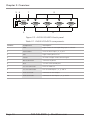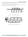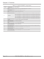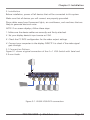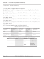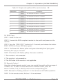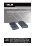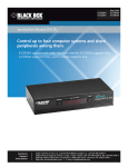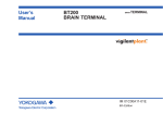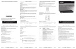
1
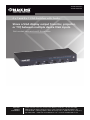
AVSW-VGA4X1A AVSW-VGA8X1A 4 x 1 and 8 x 1 VGA Switches with Audio Share a VGA display output (monitor, projector, BLACK BOX or TV) between multiple device VGA inputs. ® Both models have serial and 3.5-mm audio. Customer Support Information Order toll-free in the U.S.: Call 877-877-BBOX (outside U.S. call 724-746-5500) FREE technical support 24 hours a day, 7 days a week: Call 724-746-5500 or fax 724-746-0746 • Mailing address: Black Box Corporation, 1000 Park Drive, Lawrence, PA 15055-1018 • Web site: www.blackbox.com • E-mail: [email protected] FCC and IC RFI Statements and NOM Statement FEDERAL COMMUNICATIONS COMMISSION AND INDUSTRY CANADA RADIO FREQUENCY INTERFERENCE STATEMENTS This equipment generates, uses, and can radiate radio-frequency energy, and if not installed and used properly, that is, in strict accordance with the manufacturer’s instructions, may cause interference to radio communication. It has been tested and found to comply with the limits for a Class A computing device in accordance with the specifications in Subpart B of Part 15 of FCC rules, which are designed to provide reasonable protection against such interference when the equipment is operated in a commercial environment. Operation of this equipment in a residential area is likely to cause interference, in which case the user at his own expense will be required to take whatever measures may be necessary to correct the interference. Changes or modifications not expressly approved by the party responsible for compliance could void the user’s authority to operate the equipment. This digital apparatus does not exceed the Class A limits for radio noise emission from digital apparatus set out in the Radio Interference Regulation of Industry Canada. Le présent appareil numérique n’émet pas de bruits radioélectriques dépassant les limites applicables aux appareils numériques de la classe A prescrites dans le Règlement sur le brouillage radioélectrique publié par Industrie Canada. Normas Oficiales Mexicanas (NOM) Electrical Safety Statement INSTRUCCIONES DE SEGURIDAD 1. Todas las instrucciones de seguridad y operación deberán ser leídas antes de que el aparato eléctrico sea operado. 2. Las instrucciones de seguridad y operación deberán ser guardadas para referencia futura. 3. Todas las advertencias en el aparato eléctrico y en sus instrucciones de operación deben ser respetadas. 4.Todas las instrucciones de operación y uso deben ser seguidas. Page 2 724-746-5500 | blackbox.com NOM Statement 5. El aparato eléctrico no deberá ser usado cerca del agua—por ejemplo, cerca de la tina de baño, lavabo, sótano mojado o cerca de una alberca, etc. 6. El aparato eléctrico debe ser usado únicamente con carritos o pedestales que sean recomendados por el fabricante. 7. El aparato eléctrico debe ser montado a la pared o al techo sólo como sea recomendado por el fabricante. 8. Servicio—El usuario no debe intentar dar servicio al equipo eléctrico más allá lo descrito en las instrucciones de operación. Todo otro servicio deberá ser referido a personal de servicio calificado. 9. El aparato eléctrico debe ser situado de tal manera que su posición no interfiera su uso. La colocación del aparato eléctrico sobre una cama, sofá, alfombra o superficie similar puede bloquea la ventilación, no se debe colocar en libreros o gabinetes que impidan el flujo de aire por los orificios de ventilación. 10. El equipo eléctrico deber ser situado fuera del alcance de fuentes de calor como radiadores, registros de calor, estufas u otros aparatos (incluyendo amplificadores) que producen calor. 11. El aparato eléctrico deberá ser connectado a una fuente de poder sólo del tipo descrito en el instructivo de operación, o como se indique en el aparato. 12. Precaución debe ser tomada de tal manera que la tierra fisica y la polarización del equipo no sea eliminada. 13. Los cables de la fuente de poder deben ser guiados de tal manera que no sean pisados ni pellizcados por objetos colocados sobre o contra ellos, poniendo particular atención a los contactos y receptáculos donde salen del aparato. 14. El equipo eléctrico debe ser limpiado únicamente de acuerdo a las recomendaciones del fabricante. 15. En caso de existir, una antena externa deberá ser localizada lejos de las lineas de energia. 16. El cable de corriente deberá ser desconectado del cuando el equipo no sea usado por un largo periodo de tiempo. 17. Cuidado debe ser tomado de tal manera que objectos liquidos no sean derramados sobre la cubierta u orificios de ventilación. 724-746-5500 | blackbox.com Page 3 NOM Statement 18.Servicio por personal calificado deberá ser provisto cuando: A: El cable de poder o el contacto ha sido dañado; u B: Objectos han caído o líquido ha sido derramado dentro del aparato; o C: El aparato ha sido expuesto a la lluvia; o D: El aparato parece no operar normalmente o muestra un cambio en su desempeño; o E: El aparato ha sido tirado o su cubierta ha sido dañada. Page 4 724-746-5500 | blackbox.com Trademarks Used in this Manual Trademarks Used in this Manual Black Box and the Double Diamond logo are registered trademarks of BB Technologies, Inc. Xbox is a registered trademark of Microsoft Corporation. Wii is a registered trademark of Nintendo of America, Inc. Any other trademarks mentioned in this manual are acknowledged to be the property of the trademark owners. 724-746-5500 | blackbox.com Page 5 Table of Contents Table of Contents 1. Specifications .............................................................................................. 7 2. Overview .............................................................................................. 8 2.1 Introduction........................................................................................ 8 2.2 Features.............................................................................................. 8 2.3 What’s Included.................................................................................. 8 2.4 Hardware Description......................................................................... 9 2.4.1 AVSW-VGA4X1A Front and Back Panels............................... 9 2.4.2 AVSW-VGA8X1A Front and Back Panels..............................11 3. Installation .............................................................................................13 3.1 Connection Pattern............................................................................13 3.2 Installation Steps................................................................................14 4. Operation (AVSW-VGA4X1A).......................................................................15 4.1 Front-Panel Indicators and Push Buttons............................................15 4.2 IR Remote Control.............................................................................15 4.3 Serial Control.....................................................................................16 5. Operation (AVSW-VGA8X1A).......................................................................18 5.1 Front-Panel Indicators and Push Buttons............................................18 5.2 EDID Copy.........................................................................................19 5.3 Remote Control.................................................................................19 6. Troubleshooting.......................................................................................... 22 6.1 Contacting Black Box........................................................................ 22 6.2 Shipping and Packaging................................................................... 22 Page 6 724-746-5500 | blackbox.com Chapter 1: Specifications 1. Specifications Maximum Video Resolution — 1920 x 1080, WUXGA (1920 x 1200) Number of A/V Inputs — Video: AVSW-VGA4X1A: (4); AVSW-VGA8X1A: (8); Audio: AVSW-VGA4X1A: (4); AVSW-VGA8X1A: (8) Number of A/V Outputs — Video: (1); Audio: (1) Remote Control Support — Yes Serial Control Support — Yes Enclosure — Metal User Controls — AVSW-VGA4X1A: (4) push buttons; AVSW-VGA8X1A: (4) push buttons, (1) “S” button, (1) EDID copy button, Connectors — AVSW-VGA4X1A: Input: (4) VGA female, (4) audio jacks; Output: (1) VGA female, (1) audio jack, (1) 2.5-mm RS-232 serial; AVSW-VGA8X1A: Input: (8) VGA female, (8) audio jacks; Output: (1) VGA female, (1) audio jack, (1) 2.5-mm RS-232 serial Indicators — AVSW-VGA4X1A: (5) LEDs: (1) Power (green), (4) Video input (yellow); AVSW-VGA8X1A: (9) LEDs: (1) Power (green and yellow), (8) Video input (yellow) Power Consumption (Maximum) — 4.5 W Size — 1.3"H x 8.7"W x 3.9"D (3.4 x 22 x 10 cm) Weight — 1.5 lb. (0.7 kg) 724-746-5500 | blackbox.com Page 7 Chapter 2: Overview 2. Overview 2.1 Introduction The 4- and 8-Port VGA Switches enable users to quickly and easily share a single VGA display with several sources from your device inputs to one output device (monitor, projector, or TV). You can select the desired input source via the remote control within the range of 15 feet (5 m) or by using a push button on the switch. Because you don’t need to plug and unplug video sources, it’s more convenient, more affordable, and more efficient to use your A/V equipment. The built-in serial interface on the AVSW-VGA4X1A and AVSW-VGA8X1A also enables users to control the unit via an RS-232/serial device. 2.2 Features • Switch between (4) or (8) sources. • Switch audio and video. • Use front-panel buttons for easy switching. • Supports IR remote control. • Supports serial remote control. • LEDs show the status of input video and audio. • Supports VGA monitors at resolutions up to 1920 x 1200. 2.3 What’s Included Your package should contain the following items. If anything is missing or damaged, contact Black Box Technical Support at 724-746-5500 or [email protected]. AVSW-VGA4X1A: • 4 x 1 VGA/Audio Switch • Universal power supply with power cord • IR remote control • Serial cable (DB9 F to 2.5-mm plug) • 19" rackmount kit wth mounting hardware • (1) set of foot pads • Screw pack • This user’s manual Page 8 724-746-5500 | blackbox.com Chapter 2: Overview AVSW-VGA8X1A: • 8 x 1 VGA Video Switch with Audio • Universal power supply with power cord • IR remote control • Serial cable (DB9 F to 2.5-mm plug) • 19" rackmount kit wth mounting hardware • (1) set of foot pads • Screw pack • This user’s manual For both models, you might also need: • Audio cable (EJ110) • 6-ft. (1.8-m) VGA Cable (M-to-M) for VGA A/V source connection (EVNPS06). 2.4 Hardware Description 2.4.1 AVSW-VGA4X1A Front and Back Panels Figure 2-1 shows the front panel of the AVSW-VGA4X1A. Figure 2-2 shows the back panel. Table 2-1 describes its components. 1 2 4 3 Figure 2-1. AVSW-VGA4X1A front panel. 724-746-5500 | blackbox.com Page 9 Chapter 2: Overview 5 6 9 7 8 10 Figure 2-2. AVSW-VGA4X1A back panel. Table 2-1. AVSW-VGA4X1A components. Number Component Description 1 LEDs Lights when the corresponding input is selected. 2 Push buttons Press to select input 1, 2, 3, or 4. 3 LED Lights when power is on. 4 Sensor IR sensor accepts remote control signal. 5 Barrel connector Connects to power. 6 DCE 2.5-mm serial control port. 7 3.5-mm connector Links to audio out. 8 3.5-mm connectors Link to audio inputs 1, 2, 3, and 4. 9 VGA connector Connects to VGA output. 10 VGA connectors Connects to VGA inputs 1, 2, 3, and 4. Page 10 724-746-5500 | blackbox.com Chapter 2: Overview 2.4.2 AVSW-VGA8X1A Front and Back Panels Figure 2-3 shows the front panel of the AVSW-VGA8X1A. Figure 2-4 shows the back panel. Table 2-2 describes its components. 2 5 3 4 1 Figure 2-3. AVSW-VGA8X1A front panel. 6 7 8 11 9 10 12 Figure 2-4. AVSW-VGA8X1 back panel. 724-746-5500 | blackbox.com Page 11 Chapter 2: Overview Table 2-2. AVSW-VGA8X1A components. Number Component Description 1 LEDs Lights when the corresponding input is selected. 2 Push buttons Press to select input 1, 2, 3, 4. 3 LED Lights when power is on. Press and hold the “S” button, then press the “K1” button to select Port 5. 4 S button Press and hold the “S” button, then press the “K2” button to select Port 6. Press and hold the “S” button, then press the “K3” button to select Port 7. Press and hold the “S” button, then press the “K4” button to select Port 8. 5 Sensor IR sensor accepts remote control signal. 6 Barrel connector Connects to power. 7 DCE 2.5-mm serial control port. 8 3.5-mm connector Links to audio out. 9 EDID copy button Connects the monitor to the switch so that the switch can copy the EDID. 10 VGA connectors Connects to VGA inputs 1, 2, 3, 4, 5, 6, 7, 8. 11 VGA connector Connects to VGA output. 12 3.5-mm connectors Link to audio inputs 1, 2, 3, 4, 5, 6, 7, and 8. Page 12 724-746-5500 | blackbox.com Chapter 3: Installation 3. Installation Before installation, power off all devices that will be connected to this system. Make sure that all devices you will connect are properly grounded. Place cables away from fluorescent lights, air conditioners, and machines that are likely to generate electrical noise. NOTE: If no screen displays, follow these steps: 1. Make sure the device cables are correctly and firmly attached. 2. Set your display device’s input source as VGA. 3. Check the PC BIOS configuration for the video output settings. 4. Connect your computer to the display DIRECTLY to check if the video signal gets through. 3.1 Connection Pattern Figure 3-1 shows a typical connection of the 4 x 1 VGA Switch with Serial and 3.5-mm Audio. 4 1 2 3 3 3 3 Figure 3-1. AVSW-VGA4X1A connection. 724-746-5500 | blackbox.com Page 13 Chapter 3: Installation Table 3-1. Connection pattern, AVSW-VGA4X1A. Number Component Description 1 Power supply Apply the proper power to the unit. 2 Video output Connects to the display. 3 Video source (input) Connects to the video source. 4 Serial connector Plug the serial cable in here. 3.2 Installation Steps 1. Use a video cable (VGA) to connect the display to the video output port on the back of the switch. Plug a set of audio jacks from the speaker to the switch’s speaker port. 2. Use a video cable (VGA) to connect the source device to the video input port on the switch. Use an audio cable to connect the speaker port from the input side of the unit to the corresponding output port on the source device. 3. Plug the power supply into the switch and power on the switch. 4. Turn on the display (monitor, projector, or TV) and then power on the source device(s). NOTE: For both AVSW-VGA4X1A and AVSW-VGA8X1A, each video source is powered on, make sure it has a display pointing to it for EDID communication. If a source does not have a display pointing to it, a video image might not display. Page 14 724-746-5500 | blackbox.com Chapter 4: Operation (AVSW-VGA4X1A) 4. Operation (AVSW-VGA4X1A) 4.1 Front-Panel Indicators and Push Buttons Figure 4-1. AVSW-VGA4X1A. Table 4-1. Front-panel indicators. Product Code AVSW-VGA4X1A Indicator Description Power LED Lights green when the video switch is powered on. Video Port LEDs 1–4 Lights yellow when the corresponding video port is selected. Table 4-2. Front-panel push buttons. Product Code Push Buttons Description AVSW-VGA4X1A (4) Video source Press the corresponding button to select Ports 1–4. 4.2 IR Remote Control Using the included remote control, users can control the switch within a range of 15 feet (5 m). To select a source device with a remote control, press the number button (1–4 or 1–8, depending on the model) to directly switch to the corresponding port. NOTE: Remove the “battery protector” on the remote control before operation. NOTE: On the remote control, only Buttons 1–4 are activated. 724-746-5500 | blackbox.com Page 15 Chapter 4: Operation (AVSW-VGA4X1A) Figure 4-2. Remote control. 4.3 Serial Control The video switch’s built-in serial interface allows users to control the switch through a PC, serial controller devices, or home theater systems. Configure the controller’s serial port as shown below: Baud Rate: 9600 Data Bits: 8 Parity: None Stop Bits: 1 Flow Control: None Page 16 724-746-5500 | blackbox.com Chapter 4: Operation (AVSW-VGA4X1A) To select a source device via serial interface, select the number that corresponds to the port it is connected to (see Figure 4-3). Figure 4-3. Serial interface screen. NOTE: Use a DB9F-to-2.5-mm cable for the serial connection. 724-746-5500 | blackbox.com Page 17 Chapter 5: Operation (AVSW-VGA8X1A) 5. Operation (AVSW-VGA8X1A) 5.1 Front-Panel Indicators and Push Buttons To select Source Ports 1–4, simply press the corresponding front-panel button (K1–K4) on the switch. To select Source Port 5, press and hold the “S” button on the switch, then press K1 to select Port 5. To select Source Port 6, press and hold the “S” button on the switch, then press K2 to select Port 6. To select Source Port 7, press and hold the “S” button on the switch, then press K3 to select Port 7. To select Source Port 8, press and hold the “S” button on the switch, then press K4 to select Port 8. NOTE: Each port selection step should be individual. Table 5-1. Push button controls. Start with this key sequence… Then press the “K1” key to select… Or press the “K2” key to select… Or press the “K3” key to select… Or press the “K4” key to select… None Source 1 Source 2 Source 3 Source 4 Press hold the “S” key for more than 3 seconds. Source 5 Source 6 Source 7 Source 8 Table 5-2. Dual-color (green and red) LED next to S button. LED Next to “S” button Page 18 Mode LED Color LED State Green Turns green when the video switch is powered on. Yellow Turns yellow when the port is selected. Status 724-746-5500 | blackbox.com Chapter 5: Operation (AVSW-VGA8X1A) Table 5-3. Single-color (yellow) LEDs next to buttons 1–8. LED Number Color Description 1 Yellow The video port on Source 1 is selected. 2 Yellow The video port on Source 2 is selected. 3 Yellow The video port on Source 3 is selected. 4 Yellow The video port on Source 4 is selected. 5 Yellow The video port on Source 5 is selected. 6 Yellow The video port on Source 6 is selected. 7 Yellow The video port on Source 7 is selected. 8 Yellow The video port on Source 8 is selected. 5.2 EDID Copy STEP 1: Power on the unit. STEP 2: Connect the EDID compliant monitor to the switch and power on the monitor. STEP 3: Press the “EDID COPY” button for 3–5 seconds, and release the button RIGHT AFTER the Power LED flashes green. STEP 4: The Power LED flashes yellow and green alternately then lights green indicating the copy is successful. NOTE: If the Power LED flashes yellow, the reason could be: 1. The monitor is not connected. 2. The monitor is not powered on. 3. The EDID data of the monitor is not applicable. 5.3 Remote Control Using the included remote control, users can control the switch within a range of 15 feet (5 m). To select a source device with a remote control, press the button number (1–8), to directly switch to the corresponding port. NOTE: Remove the “battery protector” on the remote control before operation. NOTE: On the remote control, Buttons 1–8 are activated. 724-746-5500 | blackbox.com Page 19 Chapter 5: Operation (AVSW-VGA8X1A) Figure 5-1. Remote control. Page 20 724-746-5500 | blackbox.com Chapter 6: Troubleshooting 6. Troubleshooting 6.1 Contacting Black Box If you determine that your VGA switch is malfunctioning, do not attempt to alter or repair the unit. It contains no user-serviceable parts. Contact Black Box Technical Support at 724-746-5500 or [email protected]. Before you do, make a record of the history of the problem. We will be able to provide more efficient and accurate assistance if you have a complete description, including: • the nature and duration of the problem. • when the problem occurs. • the components involved in the problem. • any particular application that, when used, appears to create the problem or make it worse. 6.2 Shipping and Packaging If you need to transport or ship your VGA switch: • Package it carefully. We recommend that you use the original container. • If you are returning the unit, make sure you include everything you received with it. Before you ship for return or repair, contact Black Box to get a Return Authorization (RA) number. 724-746-5500 | blackbox.com Page 21 NOTES Page 22 724-746-5500 | blackbox.com NOTES 724-746-5500 | blackbox.com Page 23 Black Box Tech Support: FREE! Live. 24/7. Tech support the way it should be. Great tech support is just 30 seconds away at 724-746-5500 or blackbox.com. About Black Box Black Box Network Services is your source for an extensive range of networking and infrastructure products. You’ll find everything from cabinets and racks and power and surge protection products to media converters and Ethernet switches all supported by free, live 24/7 Tech support available in 30 seconds or less. © Copyright 2012. Black Box Corporation. All rights reserved. AVSW-VGA4X1A, version 1 724-746-5500 | blackbox.com