1
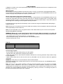
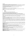
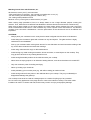
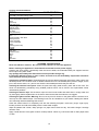
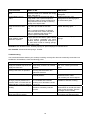
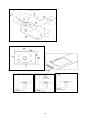
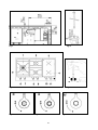
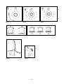
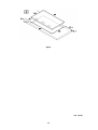
INSTALLATION, MAINTENANCE AND USE INSTRUCTIONS FOR Model PM363I0X DIMENSIONS: (890 mm)(W) (520 mm)(D) IMPORTANT: SAVE FOR LOCAL ELECTRICAL INSPECTOR’S USE. READ AND SAVE THESE INSTRUCTIONS FOR FUTURE REFERENCE. OBSERVE ALL GOVERNING CODES AND ORDINANCES. WARNING: If the information in this manual is not followed exactly, a fire or explosion may result causing property damage, personal injury or death. Do not store or use gasoline or other flammable vapors and liquid in the vicinity of this or any other appliance. WHAT TO DO IF YOU SMELL GAS - Do not try to light any appliance. - Do not touch any electrical switch. - Do not use any phone in your building. - Immediately call your gas supplier from a neighbor’s phone. Follow the gas supplier’s instructions. - If you cannot reach your gas suppliers, call the fire department. Installation and service must be performed by a qualified installer, service agency or the gas supplier. Read this instruction booklet before installing and using the appliance. By ensuring this product is disposed of correctly, you will help prevent potential negative consequences for the environment and human health, which could otherwise be caused by inappropriate waste handling of this product. The symbol on the product indicates that this product may not be treated as household waste. Instead it shall be handed over to the applicable collection point for the recycling of electrical and electronic equipment. Disposal must be carried out in accordance with local environmental regulations for waste disposal. For more detailed information about treatment, recovery and recycling of this product, please contact your local city council office. The manufacturer will not be responsible for any damage to property or to persons caused by incorrect installation or improper use of the appliance. The manufacturer reserves the right to make changes to its products when considered necessary and useful, without affecting the essential safety and operating characteristics. This appliance has been designed for non-professional, domestic use only. 2 INDEX: Installation Instructions……………………………………..………………………………………… Inserting the hotplate……………………………………………..………………………………….. Requirements……………………………………..……………………………….…………………. Attaching the hotplate……………………………………..…………………………………………. Gas connection……………………………………..…………………………………………………. Electrical connection……………………………………..……………………….…………………. Room ventilation…………………………………….……………………………………………….. Location and venting…………………………………….………………………………………….. Replacement of nozzles……………………………………..……………………………………… Regulation of burners……………………………………………...……………………………….. Descriptions…………………………………………………………………………………………… User instructions……………………………………………..………………………………………. Using burners……………………………………………………..………………………………….. Using ceramic induction elements…………………………………………………………………. Cleaning the appliance……………………………………………..……………………………….. Service and Maintenance……………………………………………..……………………………….. After Sales Service and Spare Parts…………………………………..……………………………….. Figures………………………………………………...…………..………………………………….. pag.3 pag.4 pag.4 pag.5 pag.5 pag.6 pag.7 pag.7 pag.7 pag.7 pag.7 pag.8 pag.10 pag.11 pag.15 pag.17 pag.18 pag.19 Before Installation If receiving the unit from a transportation company, it is customer’s obligation to inspect the package and note any damage on the delivery receipt. After delivery have your induction cooktop carefully unpacked, and again check for any visible damage. If you find any damage on the unit at this point, immediately inform your dealer or distributor. Although the responsibility for shipping lies with the carrier, your dealer/dis-tributor will assist you with your claim. If the unit is not supposed to be installed for some time, you should keep it in its original packaging, stored in a dry and safe place. Read through the sections of this manual which pertains to installation, and make sure that all of the requirements can be met. Ensure that your electric power supply is correct. INSTALLATION INSTRUCTIONS This appliance shall only be installed by an authorized person. This appliance shall be installed in accordance with the manufacturers installation instructions, IMPORTANT: this appliance must be installed in accordance with the norms in force of the country concerned. This appliance shall be installed only by authorised persons and in accordance with the manufacturer's installation instructions, local gas fitting regulations, municipal building codes, electrical wiring regulations, local water supply regulations, AS/NZS 5601.1-2010-Gas Installations– General installations and any other statutory regulations. This appliance is not intended to be operated by means of an external timer or separate remotecontrol system. NOT FOR USE IN MARINE CRAFT, CARAVANS OR MOBILE HOMES UNLESS EACH BURNER IS FITTED WITH FLAME SAFEGUARD. WARNING: SERVICING SHOULD BE CARRIED OUT ONLY BY AUTHORISED PERSONNEL. DO NOT MODIFY THIS APPLIANCE. INFORMATION FOR THE INSTALLER The installation, all regulations, changes and maintenance referred to in this part must only be carried out by qualified staff. A wrong installation can cause damage to persons, animals or things which the manufacturer cannot be held responsible for. The safety and automatic regulation devices on the appliances can only ever be changed by the manufacturer or by the supplier which has been authorised to do so. 3 INSERTING THE HOTPLATE After having removed the various loose parts from the internal and external packing, make sure that the hotplate in not damaged and is suitable for the specific gas usage. The gas type label is on the underside of the hotplate base. In case of doubt, do not use the appliance and contact skilled personnel. Keep all the packing parts (polystyrene foam, cardboard, staples, etc.) away from children. Consider the critical dimensions of the appliance, before making an opening in the top surface of the bench top. (relative measurements as per Fig 1- 2 & 21). If your counter is produced from porous materials which tend to swell if in contact with humidity, and water, to better protect the cut-out, use proper sea-lants on the edge which would prevent any penetration of humidity and water. Chamfer all exposed edges of decorative laminates to prevent further chipping. Radius corners of the cut-out and file them to ensure smooth edges and prevent corner cracking. Rough edges and inside corners which are not rounded as well as forced fits can contribute to cracking of counter top laminate. Requirements 1. Overhead clearances (Minimum values) The minimum overhead clearances shall be in accordance with the minimum values indicated in the table n.1 and are shown and in the fig. 1- 2 Range hoods and exhaust fans shall be installed in accordance with the manufacturer’s instructions. However, in no case shall the clearance between the top of the highest burner of the cooking appliance and the range hood be less than 650mm. Any other downward facing combustible surface less than 600mm above the top of the highest burner shall be protected for the full width and depth of the cooking surface area. However, in no case shall this clearance to any surface be less than 450mm. Maximum depth for the overheads cabinet is 330mm 2. Side clearances (Minimum values) The different side clearances shall be in accordance with the minimum values indicated in the table n.1 and are shawn and in the fig. 1- 2 The cooking surface area is defined as that part of the appliance where cooking normally takes place and does not include those parts of the appliance containing control knobs. Table n.1 Min. Clearances mm Min. Clearances mm L1 500 L10 860 L2 40 L11 915 L3 50 W 890 L4 457 D 520 L5 600 B1 (*) 40* L6 330 B2 (*) 152* L7 925 B3 (*) 40* L8 40 B4 (*) 152* L9 172 (*) Note: -B1 is the min. clearance between the front edge of the appliance and the front edge of the cabinet. -B2 and B4 are the min. clearance between the left/right side edge of the appliance and the side wall (if present). -B3 is the min. clearance between the back edge of the appliance and the back wall. -L2 plus L8 is the minimum distance from the top of the bench to the top of the board fitted to prevent access to the underside of the appliance. CAUTION: The surface temperature of the underside of the appliance exceeds 95°C during operation. To avoid a hazard, underbench access must be restricted. Refer to figure 1. 4 ATTACHING THE HOTPLATE To prevent liquids from leaking accidentally into the underlying storage space, the appliance is equipped with a special gasket. To apply this gasket, carefully follow the instructions in Fig. 3. Lay out the protective sealing strips along the edges of the opening in the bench top and carefully overlap the strip end. (See Fig. 3). insert the hotplate into the bench top opening. With a screwdriver assemble the brackets to the hotplate bottom by means of the screws . (See Fig. 4A-4B). Slide the hooks into position and secure them with the screws. Trim the part of the sealing strips which extend beyond the hotplate base Data Label - The Data Label is located on the bottom of the appliance. A duplicate Data Label is supplied to adhere in an accessible area next to the appliance. This appliance is suitable for Natural Gas and Universal LPG; ensure that the available gas supply matches the Data Label and the gas type label. GAS CONNECTION Before connecting the appliance to the gas supply, first remove the plastic plug on which is pressfitted into the gas inlet union; to remove, just pull it off. IMPORTANT INFORMATION CONCERNING THE INSTALLATION OF THE APPLIANCE The hob can be installed by itself, in an isolated position or inserted between two kitchen units or between one kitchen unit and a wall. Furthermore the back wall and surrounding surfaces must resist a temperature of 65 K. To prevent the plastic layer which covers the kitchen unit from ungluing, the glue used to join the two surfaces together must resist temperatures of up to 150 °C The installation of the appliance must be carried out according to the norms in force of the country concerned and the appliance must be installed in a well ventilated place. This appliance is not equipped with devices to remove the products of combustion. The appliance must therefore be connected following the norms for installation mentioned above. Special attention must be paid to the information below regarding aeration and ventilation of the premises. VENTILATION OF THE PREMISES To guarantee that the appliance works correctly it is necessary that the place where the appliance is installed is continuously ventilated. The volume of the premises must not be less than 25 m³ and the quantity of air needed must be based on the regular combustion of gas and on the ventilation of the premises. The natural flow of air will take place through permanent openings made in the wall of the premises to be ventilated: these openings will be connected to the outside and must have a minimum section of 100 cm² ( see Fig. 3A). These openings must be made in such a way that they cannot be obstructed. POSITION AND VENTILATION The cooking appliances that use gas must always remove the products of combustion via a hood linked to chimneys, chimney flues or via a direct connection to the outside ( see Fig. 3B ). If it is not possible to fit a hood it is possible to use a fan, fitted on the window or facing directly outside, which operates when the appliance is in use. ( see Fig. 3C ). In this way the norms in force of the country concerned regarding the ventilation of premises are strictly followed. CONNECTING THE APPLIANCE TO THE GAS SUPPLY Before connecting the appliance to the gas supply you first need to remove the plastic protective plug for the gas supply which is inserted under pressure in the gas inlet connection. To remove the plug simply unscrew it. Then make sure that the details shown on the label on the lower part of the case are compatible with those of the gas supply. A label on the last page of this manual and on the lower part of the case indicates the conditions for regulating the appliance: type of gas and pressure used. IMPORTANT: This appliance must be installed in accordance with the norms in force of the country concerned and it must only be used in a well-ventilated place. ATTENTION: Remember that the gas inlet connection for the appliance is threaded 1/2 gas cylindrical male in accordance with the norms UNI-ISO 228-1. (Fig. 10) 5 There are two ways to make the connection to the main gas line: A. The hotplate can be connected with rigid pipe as specified in AS5601 table 3.1. B. The hotplate can be connected with a Flexible Hose, which complies with AS/NZS 1869 (AGA Approved), 10mm ID, class B or D, no more than 1.2m long and in accordance with AS5601. WARNING: Ensure that the hose assembly is restrained from accidental contact with the flue or flue outlet of an underbench oven and it does not contact the hot surfaces of the hotplate, oven, dishwasher or other separate appliance that may be installed underneath or next to the hotplate. The hose should not be subjected to abrasion, kinking or permanent deformation and should be able to be inspected along its entire length. Unions compatible with the hose fittings must be used and connections tested for gas leaks. The supply connection point must be accessible with the appliance installed. Fit the supplied elbow and gasket as shown in Fig.20. The gas inlet connection has a 1/2" BSP male thread. When making the connection, take care not to apply excessive stress by counterbalancing tightening force. Ensure that the available gas supply is the same as the gas type label affixed to the base of the hob. If not, contact Bertazzoni for a Gas Conversion Kit. The gas supply pressure must be adjusted in accordance with the data label for the gas type. Natural Gas The natural gas regulator supplied must be fitted for natural gas. Ensure the arrow on the regulator points towards the direction of the gas flow. The test point pressure must be adjusted to 1.00 kPa with the largest burner operating on maximum flame. Propane Gas Fit the Propane Gas test point assembly (supplied in the gas conversion kit). An AGA Approved gas regulator suitable for a supply pressure of 2.75kPa should be part of the gas tank supply. ELECTRICAL CONNECTION The appliance is equipped with a 1.2 m. cable with 3 wires ready for connection to a dedicated 3 wire grounded power supply/junction box: (fig 19). Voltage 240 V AC, Frequency 60Hz. Max Current: 3700W /15.5 A brown wire: connect to L1 (hot) ---------------: connect to L1 (hot) blue wire: connect to N (neutral) Yellow/Green wire: connect to GND (ground) A dedicated line and junction box should be used to connect the oven to a 20 A circuit. When connecting the cable directly to the mains, connection to the electricity supply must be made by an authorised person in accordance with the Wiring Rules AS/NZS3000. The installation must include a suitable isolating switch with a minimum contact opening of 3mm between the appliance and the mains. The isolating switch should be sized according to the load on the data label and should comply with current regulations (the earth wire should not be interrupted by the circuit breaker). Before making the connection check that: the switch, wiring and electrical system can support the appliance load (see data plate); the power supply system has an efficient earthing connection which complies with the provisions of current regulations; the power outlet or omnipoar circuit-breaker is easily accessible once the cooker has been installed. WARNING: If the supply cord is damaged, it must be replaced by the manufacturer or its service agent or a similarly qualified person in order to avoid a hazard. 6 ROOM VENTILATION – LOCATION AND VENTING. ATTENTION: An exhaust fan may be used with the appliance; in each case it shall be installed in conformity with the national standards in force. ATTENTION: Exhaust hood operation may affect other vented appliances; in each case it shall be installed in conformity with the national standards in force. - CHANGING THE NOZZLES FOR USE WITH OTHER TYPES OF GAS: To change the nozzles of the burners use the following procedure: Lift up the burners and unscrew the nozzles ( Fig. 9) using an adjustable spanner of 7 mm and change the nozzles with those designed for the new gas supply according to the information given in TABLE A shown below. TABLE A: Adapting to different types of gas Burner Types of Gas Semi-Rapid NG Propane Rapid NG Propane Dual NG Inner Propane Dual NG Outer Propane Pressure kPa 1.0 2.75 1.0 2.75 1.0 2.75 1.0 2.75 Nozzle Diameter mm. 1,17 0,73 1,50 0,92 0,80 0,50 2x1,14 2x0,73 Hourly Gas Consumption (MJ) 6,6 6,9 11,0 10,8 3,1 3,1 12,5 13,9 CAUTION: save the orifices removed from the appliance for future use Regulation of burners Regulation of the "MINIMUM" on the burners To regulate the minimum on the burners carry out the following procedure indicated below: 1) Turn on the burner and put the knob onto position MINIMUM ( small flame ). 2) Remove the knob ( Fig. 11) of the tap which is set for standard pressure. The knob is found on the bar of the tap itself. 3) Beside the tap bar on the work top, use a small screwdriver that fits the screw (gold) found on the lower part of the tap and turn the fixing screw to the right or left until the flame of the burner is regulated in the most suitable way to MINIMUM. 4) Make sure that that the flame does not go out when changing the position quickly from MAXIMUM to the MINIMUM position. ATTENTION: The regulation described above can be carried out only with burners using natural gas, while with burners using propane gas the screw must be fully screwed in, in a clockwise direction. DESCRIPTION DESCRIPTIVE CAPTION FOR HOB (fig.9) 1. Dual burner 2 Rapid burner 3. Rear Induction element 4. Front induction element 5. Semi-rapid burner 6. Dual out burner control knob 7. Dual in burner control knob 8. Rapid burner control knob 9. Medium burner control knob 10. Front Induction element control knob 11. Rear Induction element control knob 7 BEFORE LEAVING When the installation is complete, always check for gas leaks using a soapy solution. Never use a flame to make this check. Ignite all burners on high flame to ensure correct operation of gas valves, burners and ignition. Turn gas taps to low flame position and observe each burner to ensure they ignite completely at all ports and that the flame is stable. Conduct these checks for each burner individually and concurrently. When satisfied with the hotplate, please instruct the user on the correct method of operation. In case the appliance fails to operate correctly after all checks have been carried out, please call the Bertazzoni Service Centre. USER INSTRUCTIONS IMPORTANT SAFETY INSTRUCTIONS Proper Installation - Be sure your appliance is properly grounded and installed by a qualified technician. Never Use your Appliance for Warming or Heating the Room. WARNING: This appliance is not intended for use by persons (including children) with reduced physical, sensory or mental capabilities, or lack of experience and knowledge, unless they have been given supervision or instruction concerning use of the appliance by a person responsible for their safety. WARNING: Children should be supervised to ensure that they do not play with the appliance. DO NOT USE OR STORE FLAMMABLE MATERIALS IN THE APPLIANCE STORAGE DRAWER OR NEAR THIS APPLIANCE. DO NOT SPRAY AEROSOLS IN THE VICINITY OF THIS APPLIANCE WHILE IT IS IN OPERATION. DO NOT STORE OR USE FLAMMABLE LIQUIDS OR ITEMS IN THE VICINITY OF THIS APPLIANCE. DO NOT MODIFY THIS APPLIANCE. WARNING: If the surface is cracked, switch off the appliance to avoid the possibility of electric shock. WHERE THIS APPLIANCE IS INSTALLED IN MARINE CRAFT OR IN CARAVANS, IT SHALL NOT BE USED AS A SPACE HEATER. WARNING: SERVICING SHOULD BE CARRIED OUT ONLY BY AUTHORISED PERSONNEL. Do Not Leave Children Alone - Children should not be left alone or unattended in an area where appliance is in use. They should never be allowed to sit or stand on any part of the appliance. Wear Proper Apparel - Loose-fitting or hanging garments should never be worn while using the appliance. User Servicing - Do not repair or replace any part of the appliance unless specifically recommended in the manual. All other servicing should be referred to a qualified technician. Storage in or on Appliance - Flammable materials should not be stored near surface units. Do Not Use Water on Grease Fires - Smother fire or flame or use dry chemical or foam-type extinguisher. Use Only Dry Potholders - Moist or damp potholders on hot surfaces may result in burns from steam. Do not let potholder touch hot heating elements. Do not use a towel or other bulky cloth. 8 Use Proper Pan Size - This appliance is equipped with several, differently sized, induction elements. Select cookware having flat bottoms, large enough to cover the surface unit heating element. Proper size pots and pans will also improve efficiency. DO NOT TOUCH SURFACE UNITS OR AREAS NEAR UNITS - Surface units may be hot even though they are dark in color. Areas near surface units may become hot enough to cause burns. Do Not Heat Unopened Food Containers - Build-up of pressure may cause container to burst and result in injury.. Never Leave Surface Units Unattended at High Heat Settings - Boil-over causes smoking and greasy spillovers that may ignite. Do not use aluminum foil, aluminum liners or aluminum containers on the unit. Cookware Handles Should Be Turned inward and Not Extend Over Adjacent Surface Units - To reduce the risk of burns, and spillage due to unintentional contact with a pot/pan, which is used for cooking, the handle of the piece should be positioned so that it is turned inward, and does not extend over adjacent surface units. Do not Cook on Broken Cooktop - If cooktop should break, cleaning solutions and spillovers may penetrate the broken cooktop and create a risk of electric shock. Contact a qualified technician immediately. Clean Cooktop With Caution - If a wet sponge or cloth is used to wipe spills on a hot cooking area, be careful to avoid steam burns. Some cleaners can produce noxious fumes if applied to a hot surface. CAUTION Do not store items of interest to children in cabinets above or around the cooktop -children climbing on the cooktop to reach items, could be seriously injured. WARNINGS: Keeping appliance area clear and free from combustible materials, gasoline and other flammable vapors and liquid. Do not store dangerous or flammable material in the cabinet areas above appliance; store them in a safe place in order to avoid potential hazards. For safe use of appliance, do not use it for space heating. Do not use aerosol sprays in the vicinity of this appliance while it is in operation For description of hotplates refer to installation instructions. 9 USING BURNERS A diagram is etched on the control panel above each knob which indicates which burner corresponds to that knob. (fig.11-12-13-14) Manual ignition: Manual ignition is always possible even when the power is cut off or in the event of prolonged power failure. Turn the knob that corresponds to the burner selected counterclockwise to the MAXIMUM position at the etched star (large flame) and place a lit match up to the burner. Burners fitted with a safety device (thermocouple): Turn the knob that corresponds to the burner selected counterclockwise to the MAXIMUM position at the etched star (large flame) and then press the knob down to activate the spark ignition. Once ignited, keep pressing the knob for about 10 seconds to allow the flame to heat the thermocouple. If the burner does not remain alight after releasing the knob repeat the above procedure. If the flame does not light after the first attempt, wait 5 minutes for the gas to dissipate before attempting to re-light the burner. Note: Dual burner is composed by two burner (inside and outside); each one operates under the relative gas valve indipendently from the other one. Note: It is recommended not to try to ignite the burner if the relative flame cap is not in the correct position Tips for using burners correctly: WARNING: During use of each gas burner(s) adjust the burner flame size properly so it does not extend beyond the edge of the cooking utensil. This is an instruction based on safety considerations - Use suitable pots for each burner (see Fig. 17 and Table B) - When the liquid is boiling, turn down the knob to the MINIMUM position. - Always use pots with a cover. Table B Burner Medium Large Dual Recommended pan diameters (mm) (140 – 260) (180 – 260) (220 – 260) Correct usage of pans: - Dry the bottom of the pan before placing it on the hotplate. - Use pots with a flat, thick bottom, except for wok cooking. - When using the burners, ensure that the handles of the pans are correctly positioned. Keep children away from the appliance. - When cooking foods with oil and fat, which are very flammable, the user should not leave the appliance unattended. WARNING: If the power is cut off, the burners can be lit with matches. The burners equipped with a safety thermocouple can only be lit when the knob is in the MAXIMUM position (large flame etching). Note: The use of a gas cooking appliance produces heat and humidity in the room where it is installed. Therefore, proper ventilation in the room is needed and natural ventilation openings must remain unobstructed and activating the mechanical exhaust fan/range hood. Intensive and continuous use of the appliance may require additional ventilation, for example by opening a window, or increasing the power of the mechanical exhaust fan/range hood, if installed. 10 USING THE CERAMIC INDUCTION ELEMENTS Safety Precautions - Read before operating your cooktop Your induction-cooking unit has been designed for residential use and food preparation, and all of the safety parameters have been designed accordingly. The unit incorporates numerous safety devices and controls, a few of which will be mentioned below: - A number of sensors monitor the temperature of the internal components. If any of these sensors senses that the component temperature is above the limit, the power output of the unit will automatically be reduced, allowing the component to cool down. Once this is achieved, the unit will continue to operate normally at the output level set initially by the operator.. -Each induction element is equipped with a sensor which is continuously monitoring the temperature of the bottom of the pan to prevent the pan from overheating. -Each induction element is equipped with a pan sensing device. This device will not allow the element to turn on unless it senses an induction-compatible pot or pan on the element covering enough surface area. If no pot/pan is detected, the digital display will flash indicating that there is no power on the element. Once an induction-compatible piece of cookware is sitting properly on the element, the digital display will become steady, and the cookware will start heating up. Note that a small object as a fork, a spoon, a piece of jewelry, etc. will not be mistaken for a cooking utensil, and it will not trigger this sensor. Moreover, this device will distinguish between pots and pans which are and are not suitable for induction cooking. If a piece of cookware, which is not suitable for induction cooking, is placed on an element, there will be no power output on the element. We reserve the right to make any changes to internal components, as well as, to make any (cosmetic) modifications on the outside in an effort to improve our products. Users with pacemakers or defibrilators must consult with their pacemaker manufacturer or their physician prior to using this cooktop which incorporates an induction heating source. If a crack appears in the glass surface, disconnect the unit immediately to avoid any risk of electric shock. If the unit is connected directly to supply inside a junction box, then disconnect its breaker, or remove fuses manually. Do not use your cooktop until the glass top has been replaced. When cooking, never use aluminum foil, never place products wrapped in aluminum foil or products deepfrozen in aluminum packs on the cooktop. Aluminum foil could melt and damage the vitroceramic glass beyond repair. The Principle of Induction When an induction element, also called: ‘a heating zone’ or simply: ‘a coil’ - is switched on, the appropriate piece of cookware used, and a desired level of heating power selected, the electronic circuit unit (‘induction generator’ or ‘inverter’) powers up the induction element which creates a magnetic field. This magnetic field continuously changes in terms of frequency and intensity, and this creates induced ‘eddy’ currents in the bottom of the pot or pan and ultimately results in heat. The heat is transferred directly to the food being cooked. Thus, induction heat makes the cookware a direct source of heat, featuring high level of efficiency with extremely low energy loss and unparalleled heating level control. With induction cooking there is very little ‘heating inertia’. Induction cooking elements do not incorporate a heat generating element, unlike convectional electric rings, halogen or radiant elements etc, therefore, heat levels can be changed very quickly. For induction, energy efficiency is within a range of 90-95%, compared with 55-65% for conventional and radiant element, or 45% - 55% for gas fueled burners. The energy efficiency contributes to substantial energy savings, both beneficial to the owner as well as the environment. Induction cooking elements are sensitive to the cookware type being used : - If there is no cookware placed on the element, or if the cookware is not of induction grade, there will be no power emitted by the element. - If the the piece of cookware is placed partially on the element, or if it is smaller than the element, the internal sensors will reduce power to the element. 11 - If the pot/pan is fully removed from the element, the power output will be instantaneously reduced to ‘0’. The controls will turn the element off after a minute, unless the piece is returned onto the element. When compared to other methods of cooking, induction cooking has a very low level of ambient heat, thus making cooking more pleasurable, with a reduced need for ventilation. Finally, the vitroceramic glass as a cooking surface barely becomes hot and this makes cleaning much easier. When using induction elements, some cookware may produce faint humming sound. This is a normal occurrence. The noise is a result of vibrations caused by induced currents. For a proper choice of pots and pans, please see “Cookware for Your Induction” SET THE COOKING TEMPERATURE AS FOLLOWS Set he heat setting the control knob. OFF= element off 1= lowest setting 9= highest setting B= Powerboost function A= Heating accelerator Led indicator H = Residual heat B = Powerboost Function = Power ON These knobs provide control of the induction cooking zones above each knob there is indication of the zone controlled.. Push and turn the knob to the right to set the zone's operating power; the settings range from a minimum of 1 to a maximum of 9. (fig.15-16) Heating accelerator Each cooking zone is equipped with a heating accelerator. This system allows the zone to be operated at peak power for a time proportional to the heating power selected. To start the heating accelerator, turn the knob to the left, select setting "A" and then release. You now have 3 seconds to select the heating setting between 1 and 9. While the heating accelerator is in operation, the heating level can be increased at any time. The "full power" time will be modified accordingly. If the power is reduced by turning the knob anticlockwise, the heating accelerator is automatically deactivated. Powerboost Function The power function allows the user to operate each heating zone continuously at the maximum power for a time of no more than 10 minutes. This function can be used, for example, to bring a large amount of water to the boil in a hurry, or to turn up the heat under meat. Push and turn the knob clockwise and set heating level 9, then use the knob to set the "B" position and release il. "B" appears on the corresponding zone display. After 10 minutes, the power is reduced automatically, "B" led is switched off. However, the power function can be turned ott at any time by reducing the heating level.. When the power function is selected for one heating zone, the power absorbed by the second zone might be reduced to supply the maximum available energy to the first zone. If a pan is removed from the cooking zone while the power function is on, the function is switched off. 12 Child lock The child lock function prevents switching on of the control unit, to avoid unwanted operation, for example by children, While child lock is activated, no cooking zone can be used. The child-lock mode is activated by overwinding the two knobs in anti-clockwise direction for mode than 1,5 secs-alternatively: one knob for more 5 secs; AND less than 30 secs to avoid failure detection. The child-lock is disabled in the same way. Aktivation/disabling is only possible if both knob input units are in zero position. Type of pans This type of appliance can only operate with pans of special kinds. The bottom of the pan must be iron or steel/iron to generate the magnetic field necessary for the heating process Vessels made from the following materials are not suitable: glass; porcelain; pottery; steel, aluminium or copper without magnetic bottom; To check that a pan is suitable, simply piece a magnet close to its bottom: if the magnet is attracted, the pan is suitable for induction cooking. The pans used for cooking must have certain minimum diameters to ensure satisfactory operation. Pans larger than the cooking zones can also be used, but it is important to ensure that the bottom of the pan does not touch other cooking zones, and that it is always centred over the perimeter of the cooking zone. Use only vessels specially designed for induction cooking, with thick, completely flat bottom; if these are not available, the pans used must not have crowned (concave or convex) bottom. (fig.16) Residual heat Each cooking zone is equipped with a device which warns of residual heat. After any cooking zone is switched off, a ‘H’ may appear on the display. This warns that the cooking zone concerned is still very hot. Cooking can be restarted while the ‘H’ is on. Attention:Take care not to spill sugar or sweet mixtures onto the hob during cooking, or to place materials or substances which might melt (plastic or aluminium foil) on it; if this should occur, to avoid damage to the surface, turn the heating off immediately and clean with the scraper supplied while the cooking zone is still warm. If the ceramic hob is not cleaned immediately, residues may form which cannot be removed once the hob has cooled. Important!Keep a close eye on children because they are unlikely to see the residual heat warming lights. The cooking zones are still very hot for some time after use, even if they are switched off. Make sure that children never touch them. WARNING: Under no circumstance use aluminum foil or plastic containers to hold the food while cooking on a glass-ceramic hob. WARNING: Do not touch the cooking area as long as the light indicating residual heat on the glass-ceramic hob, is “on”; this indicates that the temperature in the relative area is still high. WARNING: Never place pan with bottoms which are not perfectly flat and smooth on the hob WARNING: If the surface is cracked, switch off the appliance to avoid the possibility of electric shock. Contact a service centre. WARNING: Your glass-ceramic hob is thermal shock resistant and resistant to both heat and cold. If you drop a heavy pot on your hob it will not break. On the contrary, if a hard object, such as the salt shaker or the spice bottle strikes the edge or the corner of the hob, the hob may break. WARNING: never use the glass-ceramic hob as support surface. WARNING: Metallic objects such as knives, forks, spoons and lids should not be placed on the hob surface since they can get hot. WARNING: After use, switch off the hob element by its control and do not rely on the pan detector. 13 Matching Pots & Pans with Elements, etc. All elements,14,5cm (5 3/4”), are best used: - With small pieces of cookware - but normally not smaller then 10 cm (4”); -For slow cooking and simmering (sauces, creams, etc.); -For cooking small quantities of food. Minimum 10cm (3 15/16”)pots, maximum 25cm (10”) pots. When cooking large quantities of food, it is always better to use a large diameter pot/pan covering the element. Thus, better and more efficient heat distribution will be achieved and food will be cooked evenly. When using a large pot/pan on the center element, the best results will be obtained if the pan covers the whole circumference of this burner. If the cookware only covers a portion of the outer element - this element consists of two concentric coils/elements - then the performance of the element will not be as efficient and impressive. CAUTIONS - Always place your cookware in such a way that its center is aligned with the centre of the element. - Avoid hitting the vitroceramic glass with cookware or any hard objects. The glass surface is highly resistant but not unbreakable. - Pick-up your cookware when moving them around. Do not slide them and avoid excessive rubbing of the top, as this leave scratches and erase the markings - Avoid using cookware with rough or deformed bottoms. - Avoid leaving any metal cooking accessories, knives and forks, or metal objects on the cooktop. They may get hot if left close to any heating element in use. - Avoid storing flammable products in the cabinets under your cooktop. - Never leave an empty pot/pan on an induction heating element, even when the element is turned OFF. - Only use maximum power for boiling and frying. - Never try heating up a closed can. - Avoid preheating your non-stick pans (e.g. with teflon coating) at maximum heat. - Avoid storing solid and heavy items in the cabinets above your cooktop. They may accidentally be dropped and damage the glass top. Your cooktop must never be used as a storage space or a surface for piling up of any material. Do not connect any appliances to the plugs above or near to the induction cooktop; connection cable insulation can melt if in contact with heat, and this may result in an injury and property damage. 14 Cooking recommendations FOOD KNOB POSITION Melting Chocolate, chocolate coating, butter 1-2 Heating Frozen vegetables eg.spinach Broth Thick soup Milk (without lid) 2-4 8-9 2-3 1-2 Simmering Delicate sauce Spaghetti sauce Pot roast Fish (without lid) 7-8 2-3 5-7 6-8 Cooking Rice Potatoes boild in their skins Boiled potatoes Fresh vegetable Frozen vegetable Pasta Pudding (without lid) Cereals 3-4 5-7 5-7 5-7 5-7 8-9 7-8 3-4 Frying Pork chop Chicken breast Bacon Eggs Fish Pancakes 8-9 6-7 8-9 7-8 8-9 8-9 CLEANING THE APPLIANCE: Never use abrasive cleaners. Do not use steam cleaners to clean the appliance. Before cleaning the appliance it should be disconnected from the power supply. Cleaning the work surface: periodically clean the burner heads, the enamelled steel pan supports and the burner caps using warm water. Any spillage must always be removed as soon as possible using a rag. If it become difficult to open or close a valve, do not force it, but immediately request the assistance of the technical service personnel. Cleaning the enamelled parts: Enamelled parts should be cleaned frequently with soapy water. Never use abrasive powder. Do not leave acidic or alkaline substances on the enamelled parts (such as vinegar, lemon juice, salt, tomato sauce, etc.) and do not wash the enamelled parts while they are still hot. Cleaning the stainless steel parts: Clean the parts with soapy water and dry them with a soft cloth. The shine is maintained by periodically using suitable products which can be found in the supermarket. Never use abrasive powders. Cleaning the burner caps: Lift the burner caps from the burner heads and wash them in soapy water and dry thoroughly. Before replacement on the burner head ensure that the holes are not clogged. Cleaning the glass ceramic: Warning: Do not use any kind of cleaner on the glass while the surface is hot, use only the razor blade scraper. The resulting fumes can be hazardous to your health. Heating the cleaner can chemically attack and damage the surface. Clean the surface when it is completely cool with the following exception: remove dry sugar, sugar syrup, tomato products and milk immediately with the razor blade scraper. Wipe off spatters with a clean, damp sponge or a paper towel. Rinse and dry. Use white vinegar if smudge remains; rinse. Apply a small amount of the glass ceramic cooktop cleaner. When dry, buff surface with a clean paper towel or cloth. 15 TYPE OF STAIN WHAT TO DO Minor Soak the area to be cleaned with soapy water, then wipe it. Soak the area to be cleaned with warm soapy water. Use a special scraper for vitroceramic glass to remove grease and food particles. Finish off with a cleaning sponge, then wipe it clean. Apply warm white vinegar on the stain. Let it sit, then wipe off with a soft cloth. OR Use a commercial cleaner on affected area. Note that such cleaner may leave stains on stainless steel frame, thus protect exposed stainless steel. Accumulated burnt-on stains Rings and traces of lime scale Burnt-on stains following sugar spillage, melted aluminum or plastic. - Apply special vitroceramic glass cleaner on the surface, preferably one which contains silicone (protective action).let it sit, then finish off with a cleaning sponge, then wipe it clean. ACCESSORIES or AGENTS EMPLOYED Cleaning sponges & mild detergents Cleaning sponges, mild detergents and cleaning agents for vitroceramic glass Cleaning cloth, white vinegar, or diluted descaling agent. Vitroceramic cleaning agents and sponge. Allowable: Non-abrasive Paste - Ordinary Sponge or Special Sponge for Delicate Items Not allowable: Abrasive-backed sponge - Powder Troubleshooting You have doubts about whether your cooktop is working correctly this does not necessarily mean there is a breakdown. Nevertheless, check the following points PROBLEMS When you switch the unit on the supply-line breaker trips off or the supply-line fuse burn Your cooktop makes a faint clicking noise when in operation The unit doesn’t work at all POSSIBLE CAUSES Your unit may be connected incorrectly, or there is an internal problem This noise occurs when the power is being shared between two induction elements There may be a power supply or internal problem After turning an element ON, and having a pot /pan placed on the element, there is no heat and the digital indicator continues flashing Cookware makes noise during cooking The pot/pan you are trying to use is not suitable with induction cooking or its diameters is under 10 cm (4”) Your cookware create noise from vibrations caused by induced current The cooktop gives off a smell when first used for cooking A new unit 16 WHAT SHOULD YOU DO? Have the connection checked first, if ok contact your service agent. This is a normal occurrence Check your beakers /fuses/connection cable If ok contact your service agents Use another piece of cookware suitable for induction cooking Under high power this phenomenon is normal with some types of pots and pans. There is no danger for the cooktop Use each heating element for an hour with a pan filled with water ABNORMAL OPERATION Any of the following are considered to be abnormal operation and may require servicing: • Yellow tipping of the burner flame. • Burners failing to remain alight. • Sooting up of cooking utensils. • Burners extinguished by cupboard doors. • Burners not igniting properly. • Gas valves, which are difficult to turn. In case the appliance fails to operate correctly, contact Bertazzoni. SERVICE & MAINTENANCE INSTRUCTIONS Service and maintenance only to be carried out by an authorised person Routine maintenance Have the condition and efficiency of the gas pipe and the pressure regulator (if installed) checked periodically. If anomalies are found, do not repair components but have the faulty component replaced. To ensure good performance and safety, the gas regulator taps must be greased periodically. Periodic lubrication of the taps and any other appliance service must only be carried out by Authorised Personnel. To replace parts such as burners, valves and electric components, the hotplate must be removed from the bench top by releasing the attachment hooks, loosening the attachment screws of each burner, unscrewing the hotplate attachments nuts which are visible at the bottom of the surface, removing the hotplate top and finally replacing the defective parts. Note: if the valves must be replaced, first disassemble the ignitions switches wires. It is recommended to replace the valve gaskets each time the valve is replaced, thus ensuring a perfect seal between the body and the gas train. WARNING: Disconnect power before servicing unit. WARNING: The power cord supplied with the appliance is connected to the appliance with a type Y connection (in compliance with standards EN 60335-1, EN 60335-2-6 and subsequent amendments) for which it must be replaced by the manufacturer or its service agent or a similarly qualified person in order to avoid a hazard. WARNING: After first installation of the appliance or after any service intervention concerning main gas parts of the appliance, make the leak test using water with soap on the gas connections in order to verify the correct installation. Do not use fire for gas leak testing. Servicing of an induction unit is to be done by an authorized service agent. Contact your dealer for service location closest to your residence. Never try servicing the unit yourself. If any crack on the vitroceramic glass can be noticed, or the glass is broken DO NOT USE THE UNIT. Disconnect the electrical supply to the unit by tripping the breaker off (if the unit is hard-wired to the supply) or just unplug the unit (if there is a plug on the supply cable). 17 AFTER-SALES TECHNICAL SERVICE AND SPARE PARTS Before leaving the factory, this appliance was tested and adjusted by specialist skilled staff to give the best operating results. Any subsequent necessary repairs or adjustments must be carried out with the greatest care and attention by authorised personnel. For this reason, we strongly advise you contact the Bertazzoni Service Center, specifying the nature of the problem, the model of the equipment and the serial number. This data is provided on the data label adhered to the base of the appliance and on the duplicate data label. Always use original Bertazzoni spare parts. BERTAZZONI GROUP ABN 38 069 686 326 650 Bridge Road, Richmond, Victoria 3121 Service & Spare Parts: 1300 748 308 Bertazzoni After Sales Service - P.O. Box 543 SOMERTON VIC 3061 Email: [email protected] 18 Fig 1 Fig 2 Fig.3 Fig.3A Fig.3B Fig.3C 19 Fig. 4A Fig. 4B Fig.5 Fig.6 20 Fig.7 Fig.8 Fig.9 Fig.10 Fig.11 Fig.12 Fig.13 21 Fig.14 Fig.17 Fig.19 Fig.15 Fig.16 Fig.18 Fig.20 22 Fig.21 Cod. 310789 23