1
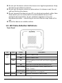
AR-7182WnA / AR-7182WnB User Manual 8-2013 / v1.0 1 COPYRIGHT Copyright Edimax Technology Co., Ltd. all rights reserved. No part of this publication may be reproduced, transmitted, transcribed, stored in a retrieval system, or translated into any language or computer language, in any form or by any means, electronic, mechanical, magnetic, optical, chemical, manual or otherwise, without the prior written permission from Edimax Technology Co., Ltd. Edimax Technology Co., Ltd. makes no representations or warranties, either expressed or implied, with respect to the contents hereof and specifically disclaims any warranties, merchantability, or fitness for any particular purpose. Any software described in this manual is sold or licensed as is. Should the programs prove defective following their purchase, the buyer (and not this company, its distributor, or its dealer) assumes the entire cost of all necessary servicing, repair, and any incidental or consequential damages resulting from any defect in the software. Edimax Technology Co., Ltd. reserves the right to revise this publication and to make changes from time to time in the contents hereof without the obligation to notify any person of such revision or changes. The product you have purchased and the setup screen may appear slightly different from those shown in this QIG. For more information about this product, please refer to the user manual on the CD-ROM. The software and specifications are subject to change without notice. Please visit our website www.edimax.com for updates. All brand and product names mentioned in this manual are trademarks and/or registered trademarks of their respective holders. Edimax Technology Co., Ltd. Add: No. 3, Wu-Chuan 3rd Rd., Wu-Ku Industrial Park, New Taipei City, Taiwan Tel: +886-2-77396888 Email: [email protected] 2 Contents 1. PRODUCT INTRODUCTION ..................................................................................................................... 5 1.1. 1.2. 1.3. 1.4. 1.5. PACKAGE CONTENTS............................................................................................................................ 5 SYSTEM REQUIREMENTS ....................................................................................................................... 5 SAFETY PRECAUTIONS .......................................................................................................................... 5 LED STATUS & BUTTON DEFINITIONS ..................................................................................................... 6 FEATURES .......................................................................................................................................... 9 2. HARDWARE INSTALLATION.................................................................................................................. 10 3. IP ADDRESS SETTING ............................................................................................................................ 17 3.1. WINDOWS 8 .................................................................................................................................... 17 3.2. WINDOWS 7 .................................................................................................................................... 20 3.3. WINDOWS VISTA .............................................................................................................................. 21 3.4. WINDOWS XP .................................................................................................................................. 22 4. EZMAX SETUP WIZARD ........................................................................................................................ 24 4.1. SETUP WIZARD ................................................................................................................................. 24 4.2. INTERNET CONNECTION TYPE .............................................................................................................. 30 4.2.1. PPoE/PPPoA ......................................................................................................................... 32 4.2.2. Bridge Mode ........................................................................................................................ 33 4.2.3. Dynamic IP Address.............................................................................................................. 34 4.2.4. Static IP ................................................................................................................................ 35 4.3. FIRMWARE UPGRADE ........................................................................................................................ 36 5. WEB CONFIGURATION ......................................................................................................................... 37 5.1. ACCESSING THE ROUTER ..................................................................................................................... 37 5.2. STATUS ........................................................................................................................................... 37 5.2.1. Device Info ........................................................................................................................... 37 5.2.2. System Log ........................................................................................................................... 38 5.2.3. Statistics ............................................................................................................................... 39 5.3. QUICK START ................................................................................................................................... 40 5.3.1. Auto setup by ISP list............................................................................................................ 43 5.3.2. Bridge Mode ........................................................................................................................ 43 5.3.3. Dynamic IP Address.............................................................................................................. 44 5.3.1. PPPoE/PPPoA ....................................................................................................................... 46 5.4. INTERFACE SETUP.............................................................................................................................. 47 5.4.1. Internet ................................................................................................................................ 47 5.4.2. LAN ....................................................................................................................................... 57 3 5.4.3. Wireless................................................................................................................................ 61 5.5. ADVANCED SETUP ............................................................................................................................. 64 5.5.1. Firewall................................................................................................................................. 64 5.5.2. Routing ................................................................................................................................. 64 5.5.3. NAT ...................................................................................................................................... 65 5.5.4. QoS ....................................................................................................................................... 69 5.5.5. VLAN .................................................................................................................................... 74 5.5.6. ADSL ..................................................................................................................................... 76 5.6. ACCESS MANAGEMENT ...................................................................................................................... 77 5.6.1. ACL ....................................................................................................................................... 77 5.6.2. Filter ..................................................................................................................................... 78 5.6.3. SNMP ................................................................................................................................... 81 5.6.4. UPnP..................................................................................................................................... 82 5.6.5. DDNS .................................................................................................................................... 83 5.6.6. CWMP .................................................................................................................................. 84 5.7. MAINTENANCE ................................................................................................................................. 85 5.7.1. Administration ..................................................................................................................... 85 5.7.2. Time Zone............................................................................................................................. 85 5.7.3. Firmware .............................................................................................................................. 86 5.7.4. SysRestart ............................................................................................................................ 87 5.7.5. Diagnostics ........................................................................................................................... 88 6. TROUBLE SHOOTING ............................................................................................................................ 89 Note: The images/screenshots used in this manual are for reference only – actual screens may vary according to firmware version. The contents of this manual are based on the most recent firmware version at the time of writing. 4 1. Product Introduction 1.1. Package Contents Before you start using this product, please check if there is anything missing in the package and contact your dealer to claim the missing item(s): ADSL2+ router (AR-7182WnA or AR-7182WnB) 12V power adapter 1 meter RJ-45 Ethernet cable 1.8M RJ-11 telephone line x 2 Quick installation guide CD containing setup wizard, user manual & multi-language QIG Splitter 5dBi antenna 1.2. System Requirements Recommended system requirements are as follows. A 10/100 base-T Ethernet card installed in your PC. A hub or Switch (connected to several PCs through one of the Ethernet interfaces on the device). Operating system: Windows 98 SE, Windows 2000, Windows ME, Windows XP, Windows 7, Windows 8. Internet Explorer V5.0 or higher, Netscape V4.0 or higher or Firefox 1.5 or higher. 1.3. Safety Precautions Follow the following instructions to prevent the device from risks and damage caused by fire or electric power: Use volume labels to mark the type of power. Use the power adapter included within the package contents. Pay attention to the power load of the outlet or prolonged lines. An overburdened power outlet or damaged lines and plugs may cause an electric shock or fire. Check the power cords regularly. If you find any damage, replace it at once. Proper space left for heat dissipation is necessary to avoid damage caused by overheating to the device. The long and thin holes on the device are designed for heat dissipation to ensure that the device works normally. Do not cover these heat dissipation holes. 5 Do not put this device close to heat sources or high temperatures. Keep the device out of direct sunshine. Do not put this device close to a place where it is damp or wet. Do not spill any fluid on this device. Do not connect this device to any PCs or electronic products, other than those which you are instructed or recommended to do so in the product’s documentation, by our customer engineers or by your broadband provider – connecting to incorrect devices may cause a fire risk. Place this device on a stable surface. 1.4. LED Status & Button Definitions Front Panel LED Color Status Power Green On ADSL2+ router is on. Off ADSL2+ router Is off. Red On ADSL broadband initial self-test failed or upgrading firmware. Green On ADSL line is synchronized and ready to use. ADSL Description Slow Flashing ADSL synchronization failed ( please refer to Note i. below) Quick Flashing ADSL negotiation is in progress. Internet Green On Internet connected in router mode 6 Flashing LAN Off Device in bridged mode. Red On Internet not connected in router mode (Please refer to Note ii. below). Green On LAN port connected. Flashing WLAN Green Green LAN port not connected. On Successful WLAN connection. ii. WLAN activity (transferring/receiving data). Off WLAN connection failed. Off WPS is disabled. Flashing Note i. LAN activity (transferring/receiving data). Off Flashing WPS Internet activity (transferring/receiving data) in router mode. WPS is enabled and waiting for client to negotiate. If the ADSL LED is off, please check your Internet connection. Refer to A. Hardware Installation for more information about how to connect the router correctly. If all connections are correct, please contact your ISP to check if there is a problem with your Internet service. If the Internet LED is red, please check your ADSL LED first. If the ADSL LED is off, refer to Note 1. If the green ADSL LED is ON, please check your Internet configuration. You may need to check with your ISP that your Internet is configured correctly. 7 Rear Panel Item Power On/Off Button Power Wireless On/Off Button WPS Button LAN Reset Button Line Description Switches the router on or off. Power port for included 12V power adapter. Switch the wireless signal on or off. Activate WPS (Wi-Fi Protected Setup) RJ-45 Ethernet ports. Hold for less than 5 seconds to restart the device, and hold for more than 10 seconds to reset the device to factory default settings. RJ-11 port for standard telephone line. 8 1.5. Features The device supports the following features: Various line modes External PPPoE dial-up access Internal PPPoE/PPPoA dial-up access 1483Bridged/1483Routed with dynamic ip or static ip Multiple PVCs (8 PVCs supported) DHCP server/relay Static route Network Address Translation(NAT) DMZ Virtual Server Universal plug and play (UPnP) Dynamic Domain Name Server(DDNS) One-level password and username Network Time Protocol(NTP) Firmware upgrading through Web, TFTP, or FTP Resetting to factory defaults through Reset button or Web Diagnostic test Web interface Telnet CLI IP/MAC/URL Filter Application layer service QOS Port binding 9 2. Hardware Installation 1. Connect the ADSL line. Connect the line port of the router of the device to the modem interface of a splitter using a telephone cable. Connect a telephone to the Phone interface of the splitter using a telephone cable. Connect the Line interface of the splitter to your existing, incoming line. The splitter has three interfaces: Line: Connect to a wall phone jack (RJ-11 jack). Modem: Connect to the ADSL jack of the device. Phone: Connect to a telephone set. 2. Connect the router to your LAN network. Connect the LAN interface of the router to your PC, hub or switch using an Ethernet cable. Note: Use twisted-pair Ethernet cables to connect the router to a hub or switch. 10 3. Connect the power adapter to the router. Plug one end of the power adapter into a wall outlet and connect the other end to the 12V interface of the device. The following diagrams show how to correctly connect the router, PC, splitter and the telephone sets under two different configurations: Configuration 1 0 shows the correct connection of the router, PC, splitter and the telephone sets, with no telephone set placed before the splitter. Figure 1 –Connection diagram (Without connecting telephone sets before the splitter) 11 Configuration 2 0 shows the correct connection when a telephone set is installed before the splitter. Figure 2 - Connection diagram (Connecting a telephone set before the splitter) Note: When Configuration 2 is used, the filter must be installed close to the telephone cable. Do not use the splitter to replace the filter. Installing a telephone directly before the splitter may lead to failure of connection between the device and the central office, or failure of Internet access, or slow connection speed. If you really need to add a telephone set before the splitter, you must add a micro filter before a telephone set. Do not connect several telephones before the splitter or connect several telephones with the micro filter. 4. Check the ADSL LED status. Please check the ADSL LED on the front panel. This light indicates the status of your ADSL broadband through your telephone line. If the light is on, you can continue setup. However if the light is flashing, there is no broadband line detected. Please call your Internet Service Provider (ISP) and inform them about the flashing ADSL light to resolve the issue. 12 5. Firewall settings. Please turn off all personal firewalls before you continue the setup – firewalls can block communication between your PC and router. Note: You must use the power adapter included in the package with the router, do NOT attempt to use a third-party power adapter. 6. PC LAN IP configuration. Configure your PC’s LAN settings to automatically obtain an IP address from the router by following the steps below: 1. Click “Start” and then select “Control Panel”. 2. Click “Switch to Classic View” in the top left to show additional setting icons. 13 3. Locate the “Network Connections” icon and double-click to open network connection settings. 4. Select the “Local Area Connection” icon and right-click it to open the sub-menu, then select “Properties”. 14 5. Select “Internet Protocol (TCP/IP)” and then click “Properties” 6. Ensure that “Obtain an IP address automatically” and “Obtain DNS server address automatically” are selected and then press “OK”. 15 16 3. IP Address Setting To use the router to access the Internet, the PCs in the network must have an Ethernet adapter installed and be connected to the router either directly or through a hub or switch. The TCP/IP protocol of each PC must be installed and the IP Address of each PC has to be set in the same subnet as the router. The router’s default IP Address is 192.168.2.1 and the subnet mask is 255.255.255.0. PCs can be configured to obtain IP Address automatically through the DHCP Server of the router or a fixed IP Address in order to be in the same subnet as the router. By default, the DHCP Server of the router is enabled and will dispatch IP Address to PC from 192.168.2.100 to 192.168.2.200. It is strongly recommended to set obtaining IP address automatically. This section shows you how to configure your PC so that it can obtain an IP address automatically for either Windows 95/98/Me, 2000 or NT operating systems. For other operating systems (Macintosh, Sun, etc.), please follow the manual of the operating system. The following is a step-by-step illustration of how to configure your PC to obtain an IP address automatically for Windows 8, Windows 7, Windows Vista and Windows XP. 3.1. Windows 8 1. From the Windows 8 Start screen, you need to switch to desktop mode. Click the Desktop icon in the bottom left of the screen. 17 2. Click the Network icon and then select Open Network and Sharing Center to open the Network and Sharing Center window. 3. Click Ethernet to open the Ethernet Status window, and then select Properties. The Local Area Connection window will appear. 18 4. Check your list of Network Components. Select Internet Protocol Version 4 (TCP/IPv4) and click the Properties button. 5. In the Internet Protocol Version 4 (TCP/IPv4) Properties window, select Obtain an IP address automatically and Obtain DNS server address automatically as shown on the following screen. 19 6. Click OK (shown above) to confirm the setting. Your PC will now obtain an IP address automatically from your router’s DHCP server. Note: Please make sure that the router’s DHCP server is the only DHCP server available on your LAN. 3.2. Windows 7 1. Click the Start button and select Control Panel. Double click Network and Internet and click Network and Sharing Center, the Network and Sharing Center window will appear. 2. Click Change adapter settings and right click on the Local Area Connection icon and select Properties. The Local Area Connection window will appear. 3. Check your list of Network Components. You should see Internet Protocol Version 4 (TCP/IPv4) on your list. Select it and click the Properties button. 20 4. In the Internet Protocol Version 4 (TCP/IPv4) Properties window, select Obtain an IP address automatically and Obtain DNS server address automatically as shown on the following screen. 5. Click OK to confirm the setting. Your PC will now obtain an IP address automatically from your router’s DHCP server. Note: Please make sure that the router’s DHCP server is the only DHCP server available on your LAN. 3.3. Windows Vista 1. Click the Start button and select Settings and then select Control Panel. Double click Network and Sharing Center, the Network and Sharing Center window will appear. 2. Click Manage network connections and right click on the Local Area Connection icon and select Properties. The Local Area Connection window will appear. 21 3. Check your list of Network Components. You should see Internet Protocol Version 4 (TCP/IPv4) on your list. Select it and click the Properties button. 4. In the Internet Protocol Version 4 (TCP/IPv4) Properties window, select Obtain an IP address automatically and Obtain DNS server address automatically as shown on the following screen. 5. Click OK to confirm the setting. Your PC will now obtain an IP address automatically from your router’s DHCP server. Note: Please make sure that the router’s DHCP server is the only DHCP server available on your LAN. 3.4. Windows XP 1. Click the Start button and select Control Panel and then double click Network Connections. The Network Connections window will appear. 2. Right click on the Local Area Connection icon and select Properties. The Local Area Connection window will appear. 22 3. Check your list of Network Components. You should see Internet Protocol [TCP/IP] on your list. Select it and click the Properties button. 4. In the Internet Protocol (TCP/IP) Properties window, select Obtain an IP address automatically and Obtain DNS server address automatically as shown on the following screen. 5. Click OK to confirm the setting. Your PC will now obtain an IP address automatically from your router’s DHCP server. Note: Please make sure that the router’s DHCP server is the only DHCP server available on your LAN. 23 4. EZmax Setup Wizard You can configure the router by running the setup wizard on the CD-ROM included in the package contents. The wizard enables you to configure your Internet connection, upgrade the firmware and change the router’s password. Please follow the instructions below. Alternatively, if you lose the CD-ROM or prefer a web based setup, you can login to the ADSL router using Internet Explorer, and configure the router from there using the web-based interface. Instructions for how to do so can be found in 5. Web Configuration. 4.1. Setup Wizard 1. When you start the setup wizard, you will see the following screen. Please choose a language and follow the on screen instructions. 24 2. Please select your product. 25 3. Please ensure all hardware is correctly installed. Check the box and click “Next”. 26 4. Select your country and ISP. If your ISP is not listed, select “Other” from the list and refer to 4.2. Internet Connection Type. 27 5. Enter your ISP’s username and password and click “Apply”. On the next screen, click “Apply” again. 28 6. Please wait while the router connects to the Internet. When the router is connected successfully, you will see the screen below. 29 4.2. Internet Connection Type If your country or ISP is not listed, please select “Other” from the list. Then select your Internet connection type and click “Next”. If you are not sure, please contact your Internet Service Provider (ISP). 30 Depending on your selection, please refer to the appropriate chapter: 4.2.1. PPPoE/PPPoA 4.2.2. Bridge Mode 4.2.3. Dynamic IP Address 4.2.4. Static IP Parameter PPPoE/PPPoA Description PPPoE (PPP over Ethernet) and PPPoA (PPP over ATM) are common connection methods used for xDSL. Bridge Mode Bridge Mode is a common connection method used for xDSL modems. Dynamic IP Address Obtain an IP address automatically from your service provider. Static IP Address Uses a static IP address. Your service provider gives a static IP address to access Internet services. 31 4.2.1. PPoE/PPPoA Parameter User Name Description Enter the username exactly as your ISP assigned. Password Enter the password that your ISP has assigned to you. VPI Virtual path identifier (VPI) is the virtual path between two points in an ATM network. Its valid value is in the range of 0 to 255. Enter the correct VPI provided by your ISP. By default, VPI is set to 8. VCI Virtual channel identifier (VCI) is the virtual channel between two points in an ATM network. Its valid value is in the range of 32 to 65535 (0 to 31 is reserved for local management of ATM traffic). Enter the correct VCI provided by your ISP. By default, VCI is set to 35. Connection type Please check with your ISP the method of 32 multiplexing. In PPPoE/PPPoA mode, please select “PPPoE LLC”, “PPPoE VCMUX”, “PPPoA LLC” or “PPPoA VCMUX”. 4.2.2. Bridge Mode Parameter VPI Description Virtual path identifier (VPI) is the virtual path between two points in an ATM network. Its valid value is in the range of 0 to 255. Enter the correct VPI provided by your ISP. By default, VPI is set to 8. VCI Virtual channel identifier (VCI) is the virtual channel between two points in an ATM network. Its valid value is in the range of 32 to 65535 (0 to 31 is reserved for local management of ATM traffic). Enter the correct VCI provided by your ISP. By default, VCI is set to 35. Connection Type Please check with your ISP the method of 33 multiplexing. In Bridge Mode, please select “ADSLTYPE_ROUTER_LLC” or “ADSLTYPE_ROUTER_VCMUX”. 4.2.3. Dynamic IP Address Parameter VPI VCI Description Virtual path identifier (VPI) is the virtual path between two points in an ATM network. Its valid value is in the range of 0 to 255. Enter the correct VPI provided by your ISP. By default, VPI is set to 8. Virtual channel identifier (VCI) is the virtual channel between two points in an ATM network. Its valid value is in the range of 32 to 65535. (0 to 31 is reserved for local management of ATM traffic) Enter the correct VCI provided by your ISP. By default, VCI is set to 35. 34 Connection Type 4.2.4. Static IP Parameter VPI VCI Please check with your ISP the method of multiplexing. In Bridge Mode, please select “ADSLTYPE_ROUTER_LLC” or “ADSLTYPE_ROUTER_VCMUX”. Description Virtual path identifier (VPI) is the virtual path between two points in an ATM network. Its valid value is in the range of 0 to 255. Enter the correct VPI provided by your ISP. By default, VPI is set to 8. Virtual channel identifier (VCI) is the virtual channel between two points in an ATM network. Its valid value is in the range of 32 to 65535. (0 to 31 is reserved for local management of ATM traffic) Enter the correct 35 VCI provided by your ISP. By default, VCI is set to 35. Static IP Address Enter the IP Address assigned by your ISP. IP Subnet Mask Enter the Subnet Mask assigned by your ISP. Gateway Enter the Gateway assigned by your ISP. Connection Type Please check with your ISP the method of multiplexing. In Bridge Mode, please select “ADSLTYPE_ROUTER_LLC” or “ADSLTYPE_ROUTER_VCMUX”. 4.3. Firmware Upgrade The wizard includes a tool to upgrade the router’s firmware. Firmware can be downloaded from the Edimax website; if you wish to upload new firmware, select “Firmware Upgrade” from the menu across the top of the screen. 36 5. Web Configuration The router can also be configured using the web-based configuration interface. Follow the instructions below. 5.1. Accessing the Router To access the web-based configuration interface: 1. Open the Internet Explorer (IE) browser and enter http://192.168.2.1. 2. In the Login page that is displayed, enter the username and password. The username and password of the super user are admin and 1234. The username and password of a common user are user and user. Note: In the Web configuration page, the settings can be saved permanently. 5.2. Status In the navigation bar, click Status. In the Status page that is displayed contains Device Info, System Log and Statistics. 5.2.1. Device Info Choose Status > Device Info. The page that is displayed shows the current status and some basic settings of the router, such as model number, software version, LAN, WAN and ADSL information. 37 5.2.2. System Log Choose Status > System Log, the page shown in the following figure appears. In this page, you can view, clear or save the system log. 38 5.2.3. Statistics Choose Status > Statistics. The Statistics page that is displayed contains Ethernet Statistics, ADSL Statistics and WLAN Statistics. 5.2.3.1. Ethernet Statistics In the Traffic Statistics page, click Ethernet and the page shown in the following figure appears. In this page, you can view the statistics such as total Bytes, Collision, Error Frames and CRC Errors. 39 5.2.3.2. ADSL Statistics In the Traffic Statistic page, click ADSL and the page shown in the following figure appears. In this page, you can view the ADSL line statistics such as total PDUs, total Error Counts. 5.2.3.1. WLAN Statistics In the Traffic Statistic page, click WLAN and the page shown in the following figure appears. In this page, you can view the WLAN statistics such as transmit/receive frames count, errors count and drops count. 5.3. Quick Start The Quick Start page will guide you to configure the ADSL router to connect to your ISP (Internet Service Provider). The following sections describe these various configuration parameters. Whether you configure these parameters or use the default ones, click NEXT to enable your Internet connection. When subscribing to a broadband service, you should be aware of the method by which you are connected to the Internet. Your physical WAN device can be either PPP, ADSL or both. Technical information about your 40 Internet connection is provided by your Internet service provider (ISP). For example, your ISP provides you with the IP address (a static or dynamic IP address) for connecting to the Internet, and the protocol for communication on the Internet. In the navigation bar, click Quick Start. The page as shown in the following figure appears. 1. Click RUN WIZARD, there will pop up a new page as shown in the following figure appears. 2. Click EXIT, this page will be closed. Click NEXT, the page as shown in the following figure appears. 41 In this page, enter a new password for the admin account. After finishing all quick start settings, it will be saved and effect immediately. 3. Click NEXT, the page as shown in the following figure appears. In this page, you can select a local time zone. 4. Click NEXT, the page as shown in the following figure appears. 42 You may select Auto setup by ISP list, Dynamic IP Address, Static IP Address, PPPoE/PPPoA or Bridge Mode. 5.3.1. Auto setup by ISP list Select Auto setup by ISP list, click NEXT, and the page as shown in the following figure appears. The following table describes the parameters in this page: Field Description Country Select the country you are in. ISP Select your Internet Service Provider (ISP). Virtual path identifier (VPI) is the virtual path between two VPI points in an ATM network. Its valid value is between 0 and 255. Enter the correct VPI provided by your ISP. Virtual channel identifier (VCI) is the virtual channel between VCI two points in an ATM network. Its valid value is between 1 and 65535. Enter the correct VCI provided by your ISP. Select a connection type from the dropdown list. You may Connection select PPPoE/ PPPoA/ Dynamic IP/ Static IP/ Routered IP/ Type Bridge. 5.3.2. Bridge Mode Select Bridge Mode, click NEXT, and the page shown in the following figure will appear. 43 The following table describes the parameters in this page: Field Description Virtual path identifier (VPI) is the virtual path between two points in an ATM network. Its valid value is between 0 and VPI 255. Enter the correct VPI provided by your ISP. By default, VPI is set to 8. Virtual channel identifier (VCI) is the virtual channel between two points in an ATM network. Its valid value is between 1 VCI and 65535. Enter the correct VCI provided by your ISP. By default, VCI is set to 35. Connection You can select LLC or VC-Mux. In this example, the Type encapsulation mode is set to 1483 Bridged IP LLC. 5.3.3. Dynamic IP Address For configuration method, please refer to that of Auto setup by ISP list Select Auto setup by ISP list, click NEXT, and the page as shown in the following figure appears. 44 The following table describes the parameters in this page: Field Description Country Select the country you are in. ISP Select your Internet Service Provider (ISP). Virtual path identifier (VPI) is the virtual path between two VPI points in an ATM network. Its valid value is between 0 and 255. Enter the correct VPI provided by your ISP. Virtual channel identifier (VCI) is the virtual channel between VCI two points in an ATM network. Its valid value is between 1 and 65535. Enter the correct VCI provided by your ISP. Select a connection type from the dropdown list. You may Connection select PPPoE/ PPPoA/ Dynamic IP/ Static IP/ Routered IP/ Type Bridge. Bridge Mode. Static IP Address Select Static IP Address, click NEXT, and the page as shown in the following figure will appear. The following table describes the parameters in this page: Field Description Virtual path identifier (VPI) is the virtual path between two VPI points in an ATM network. Its valid value is between 0 and 255. Enter the correct VPI provided by your ISP. By default, 45 Field VCI Description VPI is set to 8. Virtual channel identifier (VCI) is the virtual channel between two points in an ATM network. Its valid value is between 1 and 65535. Enter the correct VCI provided by your ISP. By default, VCI is set to 35. Enter the IP address provided by your ISP. Enter the subnet mask provided by your ISP. IP Address Subnet Mask ISP Enter the default gateway provided by your ISP. Gateway Connection You can select LLC or VC-Mux. In this example, the Type encapsulation mode is set to 1483 Bridged IP LLC. 5.3.1. PPPoE/PPPoA Select PPPoE/PPPoA, click NEXT, and the page as shown in the following figure will appear. The following table describes the parameters in this page: Field Description Enter the username for PPPoE dial-up, which is provided by Username your ISP. Enter the password for PPPoE dial-up, which is provided by Password your ISP. Virtual path identifier (VPI) is the virtual path between two VPI points in an ATM network. Its valid value is between 0 and 46 Field Description 255. Enter the correct VPI provided by your ISP. By default, VPI is set to 8. Virtual channel identifier (VCI) is the virtual channel between two points in an ATM network. Its valid value is between 1 VCI and 65535. Enter the correct VCI provided by your ISP. By default, VCI is set to 35. Connection You can select LLC or VC-Mux. In this example, the Type encapsulation mode is set to PPPoE LLC. After setting, click NEXT, the page as shown in the following figure appears. Click BACK to modify the settings. Click NEXT to save the settings. Click EXIT to cancel the settings. Note: After you saving the settings in the Quick Start page, you can view this wan connection settings in the Interface Setup > Internet page. 5.4. Interface Setup In the navigation bar, click Interface Setup. The Interface Setup page that is displayed contains Internet, LAN and Wireless. 5.4.1. Internet Choose Interface Setup > Internet. The Internet page that is displayed contains ATM VC, Qos, IPv4/IPv6 and Encapsulation. Click Internet pane, the page shown in the following figure appears. In this page, you can configure the WAN interface of your router. 47 The following table describes the parameters of this page: Field Description Virtual Circuit Select a virtual circuit from the drop-list. Click PVCs Summary to view eight PVCs (from PVC0 to PVC7), and only PVC0 status is activated by default. Status You can select Activated or Deactivated for currently selected virtual circuit. VPI The virtual path between two points in an ATM network, ranging from 0 to 255. VCI The virtual channel between two points in an ATM network, ranging from 1 to 65535. ATM QoS Select the Quality of Service types for this Virtual Circuit. The ATM QoS types include CBR (Constant Bit Rate), VBR (Variable Bit Rate) and UBR (Unspecified Bit Rate). These QoS types are all controlled by the parameters specified below, including PCR, SCR and MBS. You can choose 48 Field Description CBR, UBR, rtVBR, or nrtVBR. PCR Peak cell rate (PCR) is the maximum rate at which cells can be transmitted along a connection in the ATM network. SCR Sustain cell rate (SCR) is the maximum rate that traffic can pass over PVC without the risk of cell loss. MBS Maximum burst size (MBS) is the maximum number of cells that can be transmitted at the PCR. IP Version Supports IPv4/v6 Dual Stack Internet Protocol. You can select IPv4, IPv4/IPv6 or IPv6. ISP You can choose Dynamic IP Address, Static IP Address, PPPoA/PPPoE or Bridge Mode. Configuration for different encapsulation modes are described below with the IP Version set to IPv4/IPv6. If your ISP provides an IP address automatically, you may select Dynamic IP in the ISP encapsulation. Dynamic IP is typically used for Cable services. Please enter the Dynamic IP information accordingly. 49 The following table describes the parameters of this page: Field Description IP Common Options Encapsulation You can choose 1483 Bridged IP LLC, 1483 Bridged IP VC-Mux, 1483 Routed IP LLC(IPoA) or 1483 Routed IP VC-Mux. IP Unnumbered You can choose Activated or Deactivated. Default Route You can enable or disable the default route. If enabled, the current PVC will be the default gateway to the Internet from this device. TCP MTU Option You can set a TCP MTU value. The range is from 100 to 1500. The default is 1492. IPv4 Address NAT Select whether to enable Network Address Translation (NAT) function. If you do not enable NAT, you must add a route on the uplink equipment, otherwise Internet access will fail. Normally NAT is enabled. 50 Field Description Dynamic Route Select this option to specify the Routing Information protocol (RIP) version. You can select RIP1, RIP2-B or RIP2-M. Direction You can select None, Both, IN Only or OUT Only to specify the RIP direction. None is for disabling the RIP function. Both means the ADSL Router will periodically send routing information and accept routing information then incorporate into routing table. IN only means the ADLS router will only accept but will not send RIP packets. OUT only means the ADLS router will only send but not accept RIP packets. Multicast IGMP (Internet Group Multicast Protocol) is a session-layer protocol used to establish membership in a multicast group. The ADSL Router supports both IGMP version 1 (IGMP v1) and IGMP version 2 (IGMP v2). Select Disabled to disable it. IPv6 Address DHCP IPv6 Enable Provide address assignment to hosts to include DHCP in local pools. You can choose DHCP or SLAAC. DHCP PD Enable IPv6 Prefix Delegation Options for DHCPv6. You may enable or disable DHCP PD. MLD Proxy You may enable or disable MLD Proxy. Mld proxy is enabled only for route mode. It works in an IPv6 environment. Dual Stack Lite Enable You may Enable or Disable Dual Stack Lite. The ADSL Router support IPv4/v6 Dual Stack Internet Protocol. Select Static IP Address in the ISP encapsulation to set static IP information. You will need to enter the Connection type, IP address, subnet mask and gateway address provided by your ISP. Each IP address entered must be in the 51 correct IP format, which is four IP octets separated by a dot (x.x.x.x). The router will not accept an IP address if it is not in this format. The following table describes the parameters of this page: Field Description IP Common Options Encapsulation You can choose 1483 Bridged IP LLC, 1483 Bridged IP VC-Mux, 1483 Routed IP LLC(IPoA) or 1483 Routed IP VC-Mux. Default Route You can enable or disable default route. TCP MTU Option You can set a TCP MTU value. The range is from 100 to 1500. The default is 1492. IPv4 Options Static IP Address You can enter the IP address for dial-up, which is provided by your ISP. 52 Field Description IP Subnet Mask You can enter the IP subnet mask for dial-up, which is provided by your ISP. Gateway You can enter the gate way IP for dial-up, which is provided by your ISP. NAT Select whether to enable Network Address Translation (NAT) function. If you do not enable NAT, you must add a route on the uplink equipment, otherwise Internet access will fail. Normally NAT is enabled. Dynamic Route You can select RIP1, RIP2-B or RIP2-M. Direction You can select None, Both, IN Only or OUT Only. Multicast IGMP (Internet Group Multicast Protocol) is a session-layer protocol used to establish membership in a multicast group. The ADSL Router supports both IGMP version 1 (IGMP-v1) and IGMP version 2 (IGMP-v2). Select Disabled to disable it. IPv6 Options IPv6 Address Set Static IPv6 address. IPv6 Default Gateway Set Static IPv6 Gateway. IPv6 DNS Server1 Set Static IPv6 DNS1. IPv6 DNS Server2 Set Static IPv6 DNS2. MLD Proxy You may enable or disable MLD Proxy. MLD proxy is enabled only for route mode. It works in an IPv6 environment. Dual Stack Lite Enable You may Enable or Disable the Dual Stack Lite. The ADSL Router support IPv4/v6 Dual Stack Internet Protocol. 53 Select PPPoA/PPPoE in the ISP encapsulation if your ISP requires you to use a PPPoE connection. This option is typically used for DSL services. Select Dynamic PPPoE to obtain an IP address automatically for your PPPoE connection. Select Static PPPoE to use a static IP address for your PPPoE connection. Please enter the information accordingly. The following table describes the parameters of this page: Field Description Servicename You can set the service name. Username Enter the username for PPPoE dial-up, which is provided by your ISP. Password Enter the password for PPPoE dial-up, which is provided by your ISP. 54 Field Description Encapsulation You can choose PPPoE LLC, PPPoE VC-Mux, PPPoA LLC or PPPoA VC-Mux. IP Unnumbered Select Activated or Deactivated. Connection Setting Connection You can choose Always On (Recommended), Connect On-Demand or Connect Manually. TCP MSS Option You can set a TCP MSS value. The range is from 100 to 1452. The default is 1400. IP Common Options Default Route You can enable or disable default route. IPv4 Address Get IP Address You can choose Static or Dynamic. Static IP Address You can enter the IP address for dial-up, which is provided by your ISP. IP Subnet Mask The default is 255.255.255.255. Gateway You can enter the gateway IP for dial-up, which is provided by your ISP. TCP MTU Option You can set a TCP MTU value. The range is from 100 to 1500. The default is 1492. NAT Select whether to enable Network Address Translation (NAT) function. If you do not enable NAT, you must add a route on the uplink equipment, otherwise Internet access will fail. Normally NAT is enabled. Dynamic Route You can select RIP1, RIP2-B or RIP2-M. Direction You can select None, Both, IN Only or OUT Only. Multicast IGMP (Internet Group Multicast Protocol) is a session-layer protocol used to establish membership in a multicast group. The ADSL Router supports both IGMP version 1 (IGMP v1) and IGMP version 2 (IGMP 55 Field Description v2). Select Disabled to disable it. IPv6 Address DHCP IPv6 Enable Provide address assignment to hosts to include DHCP in local pools. Choose DHCP or SLAAC. DHCP PD Enable IPv6 Prefix Delegation Options for DHCPv6. You may enable or disable DHCP PD. MLD Proxy You may enable or disable MLD Proxy. MLD proxy is enabled only for route mode. It works in an IPv6 environment. Dual Stack Lite You may Enable or Disable the Dual Stack Lite. The ADSL Router support IPv4/v6 Dual Stack Internet Protocol. Enable Select Bridge Mode in the ISP encapsulation if you want to use pass-through transmission mode. Field Description Dual Stack Lite Enable You may Enable or Disable the Dual Stack Lite. The ADSL Router supports IPv4/v6 Dual Stack Internet Protocol. 56 Field Encapsulation Description You can choose 1483 Bridged IP LLC or 1483 Bridged IP VC-Mux. After finishing, click SAVE to apply the settings of this PVC. 5.4.2. LAN Choose Interface Setup > LAN. The LAN page that is displayed contains Router Local IP, DHCP Server, DNS, Radvd and DHCPv6. In this page, you can change the IP address of the router. The default IP address is 192.168.2.1, which is the private IP address of the router. The following table describes the parameters of this page: Field Description Main IP Enter the IP address of LAN interface. It is 57 Field Description Address recommended to use an address from a block reserved for private use. This address block is 192.168.1.1192.168.255.254. Main Subnet Mask Enter the subnet mask of LAN interface. The range of subnet mask is from 255.255.0.0 to 255.255.255.254. Alias IP Address You may enter the second IP Address. Alias Subnet Mask You may enter a second subnet mask. Dynamic Route You can select RIP1, RIP2-B or RIP2-M. Direction You can select None, Both, IN Only or OUT Only. Multicast IGMP (Internet Group Multicast Protocol) is a sessionlayer protocol used to establish membership in a multicast group. The ADSL Router supports both IGMP version 1 (IGMP v1) and IGMP version 2 (IGMP v2). Select Disabled to disable it. IGMP Snoop You may select Enabled or Disabled. After activating this function, the packets of the IGMP broadcast will not be sent to the LAN interface not belonging to the group. DHCP You can choose Disabled, Enabled or Relay. If set to DHCP Server, the router can assign IP addresses, IP default gateway and DNS Servers to the host under Windows95, Windows NT and other operating systems that support the DHCP client. Starting IP Address The starting IP address for the DHCP server's IP assignment. IP Pool Count The max user pool size. Lease Time The lease time determines the period that the host retains the assigned IP addresses before the IP addresses change. The default is 259200 seconds. 58 Field Description Physical Ports When no port is selected, the LAN PC can’t get an IP from the router. DNS Relay You can choose Use Auto Discovered DNS Server Only or Use User Discovered DNS Server Only. If you select Auto Discovered, the router accepts the firstly-received DNS assignment from one of the PPPoA, PPPoE or MER enabled PVC(s) during the connection establishment. If select User Discovered, enter the IP addresses of the primary and secondary DNS servers. Primary DNS Server DNS server FOR wan and LAN Secondary DNS Server DNS server FOR wan and LAN Radvd Enable You may choose to enable or disable Radvd. The Router Advertisement Daemon (Radvd) is an open-source software product that implements link-local advertisements of IPv6 router addresses and IPv6 routing prefixes using the Neighbor Discovery Protocol (NDP). Radvd Mode You may choose Auto or Manual. Auto Prefix Select Enable or Disable. RA Flag Set You may choose ManagedAddr or Other Config. DHCP6 Server You may choose to enable or disable DHCP6 Server. DHCP6 Mode You may choose Auto or Manual for the DHCP6 Server. Dynamic Host Configuration Protocol (DHCP) allows the individual PC to obtain the TCP/IP configuration from the centralized DHCP server. You can configure this router as a DHCP server or disable it. The DHCP server can assign IP address, IP default gateway and DNS server to DHCP clients. This router can also act as a surrogate DHCP server (DHCP proxy) where it relays IP address assignment from an actual DHCP server to clients. You can enable or disable DHCP server or DHCP proxy. 59 In the DHCP field, choose Disabled, the page shown in the following figure appears. In the DHCP field, choose DHCP Relay, the page shown in the following figure appears. Enter a server IP address running on WAN side. 60 5.4.3. Wireless Choose Interface Setup > Wireless. The page as shown in the following figure appears. The Wireless page contains Access Point Settings, 11n Settings, Multiple SSIDs Settings, WPS Settings and Wireless MAC Address Filter. The following table describes the parameters of this page: Field Description Access Point Settings Access Point You may choose Activated or Deactivated. 61 Field Description Current Channel Countries apply their own regulations to both the allowable channels, allowed users and maximum power levels within these frequency ranges. The default is 2. Beacon Interval Beacon Interval range is from 20 to 1000. RTS/CTS Threshold RTS/CTS Threshold range is from 1500 to 2347. Fragmentation Threshold Enter a Fragmentation Threshold between 256 and 2346 (even numbers only). DTIM DTIM range is from 1 to 255. A delivery traffic indication message is a kind of traffic indication message (TIM) which informs the clients of the presence of buffered multicast/broadcast data on the access point. Wireless Mode Comply with the IEEE 802.11b/g and IEEE802.11n standards. You can select 802.11b, 802.11g, 802.11b+g, 802.11n, 802.11g+n or 802.11b+g+n. 11n Settings Channel Bandwidth Supports 20MHz/40MHz Dual Channel. Extension Channel The field displays whether the current extension channel is above or below the current control channel. Guard Interval You can set 800 nsec or AUTO. MCS You can set an MCS index between 0 and 7, or select AUTO. Multiple SSIDs Settings SSID index Select SSID to be modified. Broadcast SSID Select whether the router broadcasts SSID or not. You can select Yes or No. Select Yes, and the wireless client searches the 62 Field Use WPS Description router through broadcasting SSID. Select No to hide SSID. SSID is not visible to wireless client searches. WPS technology allows new customers without a previously-established account to securely connect to your network at the Wi-Fi hotspot, create and pay for an account, and access the Internet. WPS Settings WPS state WPS state is displayed here. WPS mode Select PIN code or PBC. Start WPS Click to start WPS.. WPS progress Indicates current WPS progress status. Reset to OOB Click Reset to OOB (out of box) to reset all Wi-Fi settings to default. SSID Enter an SSID. The service set identification (SSID) is a unique name to identify the router in the wireless LAN. Authentication Type Select from Disabled, WEP-64Bits, WEP-128Bits, WPA-PSK, WPA2-PSK, WPA-PSK/WPA2-PSK. Wireless MAC Address Filter Active Activate or deactivate wireless MAC address filter. Action Set Allow or Deny for listed MAC addresses. This function can be used to allow or deny access to certain wireless clients based on their MAC Address. Mac Address #1–8 You can set up to eight MAC addresses. 63 5.5. Advanced Setup In the navigation bar, click Advanced Setup. In the Advanced Setup page that is displayed contains Firewall, Routing, NAT, QoS, VLAN and ADSL. 5.5.1. Firewall Choose Advanced Setup > Firewall. The page shown in the following figure appears. You can select this option to automatically detect and block Denial of Service (DoS) attacks such as Ping of Death, SYN Flood, Port Scan and Land Attack. 5.5.2. Routing Click Advanced Setup > Routing, the page shown in the following figure appears. It displays routing table information. Click ADD ROUTE, the page shown in the following figure appears. This page is used to configure the routing information. You may add, edit or drop the static route. 64 The following table describes the parameters and buttons of this page: Field Description Destination Enter the IP address of the destination device. IP Address IP Subnet Enter the subnet mask of the destination device. Mask Gateway IP You can enter the IP address of the next hop in the IP route to Address the destination device, or bind with a PVC interface. Metric The metric cost for the destination. This parameter determines if the ADSL router will include the route to this remote node in its RIP broadcasts. If set to Yes, Announced the route to this remote node will be propagated to other in RIP hosts through RIP broadcasts. If No, this route is kept private and is not included in RIP broadcasts. 5.5.3. NAT Click Advanced Setup > NAT, the page shown in the following figure appears. In this page, you can set up the NAT (Network Address Translation) function for your ADSL router. This function allows you to share one WAN IP address for multiple computers on your LAN. 65 The following table describes the parameters and buttons of this page: Field Description Virtual Choose a Virtual Circuit Index to set up for the NAT function. Circuit This field shows the current NAT status for the current VC. The NAT Status status is enabled or disabled, depending on whether NAT is enabled for the WAN connection. This field is to specify how many IPs are provided by your ISP for the current VC. You can select Single or Multiple. When Number of you choose Single, you can set DMZ or Virtual Server. When IPs you choose Multiple, You can set DMZ, Virtual Server or IP Address Mapping (for Multiple IP Service). Note: VCs with a single IP share the same DMZ and Virtual servers. For VCs with multiple IPs, each VC can set DMZ and Virtual servers. Also, VCs with multiple IPs can define the Address Mapping rules. VCs with a single IP do not need to individually define the Address Mapping rule. Demilitarized Zone (DMZ) is used to provide Internet services without sacrificing unauthorized access to its local private network. Typically, the DMZ host contains devices accessible to Internet traffic, such as web (HTTP) servers, FTP servers, SMTP (e-mail) servers and DNS servers. In the NAT page, choose DMZ, and the page shown in the following figure appears. 66 The following table describes the parameters of this page: Field Description DMZ Select Enabled or Disabled to enable this function. DMZ Enter the specified IP Address for the DMZ host on the LAN Host IP side. Address In the NAT page, choose Virtual Server, and the page shown in the following figure appears. The Virtual Server is the server(s) behind NAT (on the LAN), for example, Web server or FTP server, which you can make visible to the outside world even though NAT makes your whole inside network appear as a single machine to the outside world. The following table describes the parameters of this page: Field Description The Virtual server rule index for this VC. You can specify 10 Rule Index rules in maximum. All the VCs with single IP will use the same Virtual Server rules. 67 Field Description You can enter an application name, or select a name from the Application right drop-list menu like FTP or TELNET. Choose the transport layer protocol that the service type. You Protocol can choose ALL, TCP or UDP. Enter the specific start and end port number you want to Start/End forward. If it is only one port, enter the end port number the Port same as start port number. For example, if you want to set the Number FTP Virtual server, you can set the start and end port number to 21. Local IP Enter the IP Address for the Virtual Server in the LAN. Address In the NAT page, select Number of IPs as Multiple, and then choose IP Address Mapping (for Multiple IP Service), and the page shown in the following figure appears. The IP Address Mapping rule is per-VC based (only for Multiple IPs' VCs). Entries in this table allow you to configure one IP pool for specified source IP address from LAN, so that one packet whose source IP is in range of the specified address will select one IP address from the pool for NAT. 68 The following table describes the parameters of this page: Field Description The Virtual server rule index for this VC. You can specify Rule Index 10 rules in maximum. All the VCs with single IP will use the same Virtual Server rules. Choose the One-to-One, Many-to-One, Many-to-Many Rule Type Overload, Many-to-Many No Overload, or Server. Enter the local IP Address you plan to map to. Local Start Local Start/End IP is the starting local IP address and Local End IP is the IP ending local IP address. If the rule is for all local IPs, then the Start IP is 0.0.0.0 and the End IP is 255.255.255.255. Enter the public IP Address you want to use for NAT. Public Start/End Public Start IP is the starting public IP address and Public IP End IP is the ending public IP address. If you have a dynamic IP, enter 0.0.0.0 as the Public Start IP. 5.5.4. QoS The QoS provides better service of selected network traffic over various technologies. This function can be set based on the physical LAN ports or wireless interfaces under IPv4 or IPv6 version respectively. IP Version: IPv4 Choose Advanced Setup > QoS, the page shown in the following figure appears. 69 The following table describes the parameters of this page: Field Description Quality of Service IP Version In this example, the IP version is set to IPv4. You may select Activated or Deactivated. After activating QoS QoS, you may set the upload bandwidth of the WAN interface. Click the QoS Settings Summary button to view the table Summary of Qos rules and actions. Rule Rule Index You may establish at most 16 QoS rules. You may select Activated or Deactivated. The QoS rule can Active be set if it is activated. Application Support application options such as IGMP, SIP, H.323, 70 Field Description MGCP, SNMP, DNS, DHCP, RIP, RSTP, RTCP and RTP. Physical Ports Choose an Ethernet interface or WLAN Interface. The Destination MAC address of the rule. If data packets Destination include the MAC address, the data packets are placed into MAC the group. The destination IP address of the rule. If data packets IP include the IP address, the data packets are placed into the group. Port Range Port Range is from 0 to 65535. The Source MAC address of the rule. If data packets include Source MAC the MAC address, the data packets are placed into the group. Protocol ID You can choose TCP/UDP, TCP, UDP, ICMP or IGMP. Select this option to Activate/Deactivate the 4094 VID on the 4 different queues. VID (VLAN ID) is the identification of the VLAN, which is basically used by the standard Vlan ID Range 802.1Q. It has 12 bits and allows the identification of 4096 (2^12) VLANs. Of the 4096 possible VIDs, a VID of 0 is used to identify priority frames and value 4095 (FFF) is reserved, so the maximum possible VLAN configurations are 4,094. IPP/DS Field You may set IPP/TOS or DSCP. IP Precedence When IPP/DS field is set to IPP/TOS, you need to enter an Range IP precedence range. Support services including Normal service, Minimize Type of Service delay, Maximize throughput, Maximize reliability and Minimize monetary cost. DSCP Range DSCP Range is from 0 to 63. Select this option to Activate/Deactivate the 802.1p. IEEE 802.1p establishes eight levels of priority (0–7). Although network managers must determine actual mappings, IEEE has made broad recommendations. Seven is the highest 802.1p priority which is usually assigned to network-critical traffic such as Routing Information Protocol (RIP) and Open Shortest Path First (OSPF) table updates. Five and six are often for delay-sensitive applications such as interactive 71 Field Description video and voice. Data classes four through one range from controlled-load applications such as streaming multimedia and business-critical traffic - carrying SAP data, for instance - down to "loss eligible" traffic. Zero is used as a best-effort default priority, invoked automatically when no other value has been set. IP Precedence For a message matching the QoS rule, its IP precedence Remarking value will be modified. Type of Service For a message matching the QoS rule, its type of service Remarking value will be modified. DSCP For a message matching the QoS rule, its DSCP value will Remarking be modified. 802.1p For a message matching the QoS rule, its 802.1P value will Remarking be modified. Queue # Select Low, Medium, High or Highest. Click Save at the bottom of the page to save the discipline. To view the rules and actions, click QoS Settings Summary to enter the page shown in the following figure appears. IP Version: IPv6 Choose Advanced Setup > QoS, the page shown in the following figure appears. 72 The following table describes the parameters of this page: Field Description Quality of Service Select IP version. In this example, the IP version is set to IP Version IPv6. Select Activated or Deactivated. After activating QoS, you QoS may set the upload bandwidth of the WAN interface. Click the QoS Settings Summary button to view the table Summary of Qos rules and actions. Rule Rule Index You may establish up to 16 QoS rules. You may select Activated or Deactivated. Activated must Active be selected to set QoS rules. The Destination MAC address of the rule. If data packets Destination include the MAC address, the data packets are placed into IPv6 the group. The Source MAC address of the rule. If data packets include Source IPv6 the MAC address, the data packets are placed into the group. DSCP Range DSCP Range is from 0 to 63. DSCP For a message matching the QoS rule, its DSCP value will Remarking be modified. Queue # Select Low, Medium, High or Highest. 73 Click Save at the bottom of the page to save the discipline. To view the rules and actions, click QoS Settings Summary to enter the page shown in the following figure appears. 5.5.5. VLAN Choose Advanced Setup > VLAN, the page shown in the following figure appears. Virtual LAN (VLAN) is a group of devices on one or more LANs that are configured so that they can communicate as if they were attached to the same wire, when in fact they are located on a number of different LAN segments. Because VLANs are based on logical instead of physical connections, it is very flexible for user/host management, bandwidth allocation and resource optimization. In the VLAN page, choose Activated and then Assign VLAN PVID for each Interface, and the page shown in the following figure appears. 74 Each physical port has a default VID called PVID (Port VID). PVID is assigned to untagged frames or priority tagged frames (frames with null (0) VID) received on this port. You can set a PVID for an ATM VC, Ethernet port or Wireless LAN. In the VLAN page, choose Activated and then Define VLAN Group, and the page shown in the following figure appears. 75 The following table describes the parameters of this page: Field Description VLAN Index Choose a VLAN index from 1 to 8. Select Yes or No to specify whether VLAN settings Active are active or not. VLAN ID VLAN ID is from 1 to 4094. ATM VCs Supports eights ATM VCs, which can be tagged. Ethernet The Ethernet port can be tagged. Wireless LAN You can add a wireless port to the VLAN group. 5.5.6. ADSL Click Advanced Setup > ADSL, the page shown in the following figure appears. The ADSL feature can be selected when you meet the physical connection problem. Please check the proper settings with your Internet service provider. 76 The router supports these modulations: G.Lite, T1.413, G.DMT, ADSL2, ADSL2+ and Auto-Syno Up. The router negotiates the modulation modes with the DSLAM. The following table describes the parameters and buttons of this page: Field Description Choose Auto Sync-Up, ADSL2+, ADSL2, G.DMT, T1.413 or ADSl Mode G.lite. The default is Auto Sync-Up. Choose ANNEX A, ANNEX I, ANNEX A/L, ANNEX M or ADSL Type ANNEX A/I/J/L/M. 5.6. Access Management In the navigation bar, click Access Management. The Access Management page that is displayed contains ACL, Filter, SNMP, UPnP, DDNS and CWMP. 5.6.1. ACL Choose Access Management > ACL, and the page shown in the following figure appears. The user may remotely access the ADSL Router once his IP has been set as a Secure IP Address through selected applications. With the default IP 0.0.0.0, any client would be allowed to remotely access the ADSL Router. 77 The following table describes the parameters and buttons of this page: Field Description ACL Rule Index You can establish sixteen ACL rules at most. Active Click to enable or disable the rule. Secure IP The rule is valid if the IP is in this range. Address Application Support Web, FTP, Telnet, SNMP, Ping or ALL. Interface Support WAN, LAN or Both. Access control Only the devices whose MAC addresses are listed in the Listing Access Control Listing can access the router. 5.6.2. Filter Choose Access Management > Filter, and the page shown in the following figure appears. Select IP/MAC Filter type. The user can set IP/MAC Filter, Application Filter and URL Filter. 5.6.2.1. IP/MAC Filter Choose Access Management > Filter, select IP/MAC Filter from the dropdown list Filter Type Selection, and the page shown in the following figure appears. The user can set different IP filter rules of a given protocol (TCP, UDP or ICMP) and a specific direction (incoming, outgoing, or both) to filter the packets. 78 The following table describes the parameters and buttons of this page: Field Description Filter Type Support IP / MAC Filter, Application Filter and URL Selection Filter. IP/MAC Filter Set You can choose an IP / MAC Filter Set Index from 1 to 12. Index You can select an interface from the eight PVCs or the Interface LAN interface. Direction Choose Both, Incoming or Outgoing. Rule Type Select IP or MAC. Source IP Enter the Source IP Address. Address Port Number Enter the Port Number. 0 means don't care. Destination IP Enter the Destination IP Address. Address Protocol Support TCP, UDP or ICMP. 79 5.6.2.2. Application Filter Choose Access Management > Filter, select Application Filter from the dropdown list Filter Type Selection, and the page shown in the following figure appears. Select Application Filter type. The user can set Application rules to filter the ICQ, MSN, YMSG, Real Audio/Video packets. The following table describes the parameters and buttons of this page: Field Description Active Choose to activate or deactivate the Application Filter rule. ICQ Set Allow or Deny ICQ packets. MSN Set Allow or Deny MSN packets. YMSG Set Allow or Deny YMSG packets. Real Set Allow or Deny Real Audio/Video packets. Audio/Video 5.6.2.3. URL Filter Choose Access Management > Filter, select URL Filter from the drop-down list Filter Type Selection, and the page shown in the following figure appears. Select URL Filter type. The user can set URL rules to prevent the LAN users to access. 80 The following table describes the parameters and buttons of this page: Field Description Active Make URL Filter rule activated or deactivated. URL Index Can set an URL Filter Index from 1 to 16. URL Enter the URL that needs to be filtered. 5.6.3. SNMP Choose Access Management > SNMP, and the page shown in the following figure appears. The SNMP (Simple Network Management Protocol) is used for exchanging information between network devices. 81 The following table describes the parameters of this page: Field Description Get Community Select to set the password for the incoming Get- and GetNext requests from the management station. Set Community Select to set the password for incoming Set requests from the management station. 5.6.4. UPnP Choose Access Management > UPnP, the page shown in the following figure appears. This page is used to configure the UPnP parameters. UPnP (Universal Plug and Play) is a distributed, open networking standard that uses TCP/IP for simple peer-to-peer network connectivity between devices. An UPnP device can dynamically join a network, obtain an IP address, convey its capabilities and learn about other devices on the network. In turn, a device can leave a network smoothly and automatically when it is no longer in use. UPnP broadcasts are only allowed on the LAN. The following table describes the parameters of this page: Field Description UPnP You can choose Activated or Deactivated. Auto-configured UPnP network devices can automatically configure network addressing, announce their presence in the network to other UPnP devices and enable exchange of simple product and service descriptions. 82 5.6.5. DDNS Choose Access Management > DDNS, the page shown in the following figure appears. The Dynamic Domain Name System (DDNS) lets you use a static host name with a dynamic IP address. User should type the host name, user name and password assigned to your ADSL Router by your Dynamic DNS provider. The user also can decide to turn on DYNDNS Wildcard or not. The following table describes the parameters of this page: Field Description Dynamic DNS Choose to activate or deactivate DDNS function. My Host Name The DDNS identifier E-mail Address The email provided by DDNS provider Username The name provided by DDNS provider Password The password provided by DDNS provider Wildcard support You can choose Yes or No. 83 5.6.6. CWMP Choose Access Management > CWMP, and the page shown in the following figure appears. The following table describes the parameters of this page: Field Description URL URL for the CPE to connect to the ACS using the CPE WAN Management Protocol. This parameter must be in the form of a valid http or https URL. User Username used to authenticate the CPE when making a Name connection to the ACS using the CPE WAN Management Protocol. Password Password used to authenticate the CPE when making a connection to the ACS using the CPE WAN Management Protocol. User CPE’s username, the connection username provided by TR-069 Name service Password CPE’s password, the connection password provided by TR-069 service for a connection request to the CPE. Periodic Select Activated to periodically connect to the ACS to check for Inform configuration updates. Interval(s) Specify the duration between two connections to ACS. 84 5.7. Maintenance In the navigation bar, click Maintenance. The Maintenance page that is displayed contains Administration, Time Zone, Firmware, SysRestart and Diagnostics. 5.7.1. Administration Choose Maintenance > Administration, the page shown in the following figure appears. There is only one account that can access the WebManagement interface. The default account is "admin" and the password is "admin" – the “admin” account has read/write access privilege. In this web page, you can set new a password for “admin”. The following table describes the parameters of this page: Field Description New Password Enter the password to which you want to change the old password. Confirm Password Enter the new password again. 5.7.2. Time Zone Choose Maintenance > Time Zone, the page shown in the following figure appears. The system time is the time used by the device for scheduling services. You can manually set the time or connect to a NTP (Network Time Protocol) server. If a NTP server is set, you will only need to set the time zone. If you manually set the time, you may also set Daylight Saving dates and the system time will automatically adjust on those dates. 85 The following table describes the parameters of this page: Field Description Synchronize You can choose NTP Server automatically, PC’s Clock or time with Manually. Choose the time zone in which area you are from the dropTime Zone down list. Daylight You can enable the daylight saving time. Saving NTP Server Set the NTP server manually. Address 5.7.3. Firmware Choose Maintenance > Firmware, the page shown in the following figure appears. You can upgrade the firmware of the Router in this page. Make sure the firmware you want to use is on the local hard drive of the computer. Click on Browse to browse the local hard drive and locate the firmware to be used for upgrade. 86 The following table describes the parameters of this page: Field Description New Firmware Click Browse to select the firmware file. Location Click Browse and select a path to save the configuration Romfile Backup file of the router. After selecting the file, click UPGRADE to starting UPGRADE upgrading the file. 5.7.4. SysRestart Choose Maintenance > SysRestart, the page shown in the following figure appears. You can restart the device with current settings or back to factory default settings. 87 The following table describes the parameters of this page: Field Description Current Settings Restart the router with current settings. Factory Default Restart the router with settings reset back to factory Settings defaults. 5.7.5. Diagnostics Choose Maintenance > Diagnositics, the page shown in the following figure appears. The page shows the test results for the connectivity of the physical layer and protocol layer for both LAN and WAN sides. The following table describes the parameters of this page: Field Description Virtual Circuit Choose a PVC from the drop down list to test. 88 6. Trouble Shooting Question Answer Check the connection between the power Why are all the indicators adapter and the power socket. off? Check whether the power switch is turned on. Check the connection between the device and Why is the LAN indicator your PC, hub or switch. off? Check the running status of the computer, hub, or switch. Why is the ADSL Check the connection between the Line port of the indicator off? device and the wall jack. Why does Internet access Check whether the VPI, VCI, user name and fail while the ADSL password are correctly entered. indicator is on? Why can I not access the web configuration page of the DSL router? How to load the default settings after incorrect configuration? Choose Start > Run from the desktop, and ping 192.168.2.1 (IP address of the DSL router). If the DSL router is not reachable, check the type of network cable, the connection between the DSL router and the PC, and the TCP/IP configuration of the PC. To restore the factory default settings, turn on the device, and press the reset button for about 3 seconds, and then release it. The default IP address and the subnet mask of the DSL router are 192.168.2.1 and 255.255.255.0, respectively. User/password of super user: admin/1234 User/password of common user: user/user 89 EU Declaration of Conformity English: French: Czechian: Polish: Romanian: Russian: Magyar: Türkçe: Ukrainian: Slovakian: German: Spanish: Italian: Dutch: Portugese: Norwegian: Swedish: Danish: Finnish: This equipment is in compliance with the essential requirements and other relevant provisions of Directive 1999/5/EC, 2009/125/EC. Cet équipement est conforme aux exigences essentielles et autres dispositions de la directive 1999/5/CE, 2009/125/CE Toto zařízení je v souladu se základními požadavky a ostatními příslušnými ustanoveními směrnic 1999/5/ES, 2009/125/ES. Urządzenie jest zgodne z ogólnymi wymaganiami oraz szczególnymi warunkami określonymi Dyrektywą UE 1999/5/EC, 2009/125/EC Acest echipament este în conformitate cu cerinţele esenţiale şi alte prevederi relevante ale Directivei 1999/5/CE, 2009/125/CE. Это оборудование соответствует основным требованиям и положениям Директивы 1999/5/EC, 2009/125/EC. Ez a berendezés megfelel az alapvető követelményeknek és más vonatkozó irányelveknek (1999/5/EK, 2009/125/EC) Bu cihaz 1999/5/EC, 2009/125/EC direktifleri zorunlu istekler ve diğer hükümlerle ile uyumludur. Обладнання відповідає вимогам і умовам директиви 1999/5/EC, 2009/125/EC. Toto zariadenie spĺňa základné požiadavky a ďalšie príslušné ustanovenia smerníc 1999/5/ES, 2009/125/ES. Dieses Gerät erfüllt die Voraussetzungen gemäß den Richtlinien 1999/5/EC, 2009/125/EC. El presente equipo cumple los requisitos esenciales de la Directiva 1999/5/EC, 2009/125/EC. Questo apparecchio è conforme ai requisiti essenziali e alle altre disposizioni applicabili della Direttiva 1999/5/CE, 2009/125/CE. Dit apparaat voldoet aan de essentiële eisen en andere van toepassing zijnde bepalingen van richtlijn 1999/5/EC, 2009/125/EC. Este equipamento cumpre os requesitos essênciais da Directiva 1999/5/EC, 2009/125/EC Dette utstyret er i samsvar med de viktigste kravene og andre relevante regler i Direktiv 1999/5/EC, 2009/125/EC. Denna utrustning är i överensstämmelse med de väsentliga kraven och övriga relevanta bestämmelser i direktiv 1999/5/EG, 2009/125/EG. Dette udstyr er i overensstemmelse med de væ sentligste krav og andre relevante forordninger i direktiv 1999/5/EC, 2009/125/EC. Tämä laite täyttää direktiivien 1999/5/EY, 2009/125/EY oleelliset vaatimukset ja muut asiaankuuluvat määräykset. -------------------------------------------------------------------------------------------------------WEEE Directive & Product Disposal At the end of its serviceable life, this product should not be treated as household or general waste. It should be handed over to the applicable collection point for the recycling of electrical and electronic equipment, or returned to the supplier for disposal. 90 Declaration of Conformity We, Edimax Technology Co., LTD., declare under our sole responsibility, that the equipment described below complies with the requirements of the European Council directive (1995/5/EC, 2006/95/EC). Equipment : Model No. : N150 Wireless ADSL Modem Router AR-7182WnA & AR-7182WnB The following European standards for essential requirements have been followed: Spectrum EMC : ETSI EN 300 328 : V1.7.1(2006-10) : EN 301 489-1 V1.9.2(2011-09) EN 301 489-17 V2.2.1(2012-09) EMF : EN 62311:2008 Safety (LVD) : IEC 60950-1 : 2005 (2ndEdition)+A1 :2009 EN 60950-1 : 2006+A11:2009+A1:2010+A12:2011 Edimax Technology Co., Ltd. No. 3, Wu Chuan 3rd Road, Wu-Ku Industrial Park. New Taipei City, Taiwan Date of Signature: Signature: Printed Name: Title: 91 August, 2013 Albert Chang Direct Director Edimax Technology Co., Ltd. 92