1
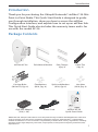
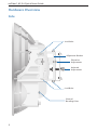
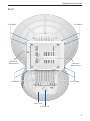
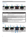
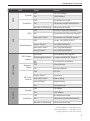
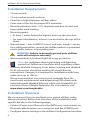
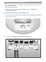
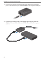
24 GHz Point to Point
1.4+ Gbps Radio
Model: AF-24
Introduction
Introduction
Thank you for purchasing the Ubiquiti Networks® airFiber® 24 GHz
Point-to-Point Radio. This Quick Start Guide is designed to guide
you through installation, show you how to access the airFiber
Configuration Interface, and explain how to set up an airFiber link.
This Quick Start Guide also includes the warranty terms and is for
use with the model AF-24.
Package Contents
airFiber AF-24
Carriage Bolts
(M10x150, Qty. 4)
Pole Mount Bracket
Flat Washers
(M10, Qty. 4)
Pole Clamps
(Qty. 2)
Cable Ties
(Qty. 3)
Split Lock Washers
(M10, Qty. 4)
Hex Nuts
(M10, Qty. 4)
24 GHz Point to Point
1.4+ Gbps Radio
Model: AF-24
GigE PoE Adapter
(50V, 1.2A)
Power Cord
airFiber AF-24
Quick Start Guide
TERMS OF USE: Ubiquiti radio devices must be professionally installed. Shielded Ethernet cable and
earth grounding must be used as conditions of product warranty. TOUGHCable™ is designed for
outdoor installations. It is the customer’s responsibility to follow local country regulations, including
operation within legal frequency channels, output power, and Dynamic Frequency Selection (DFS)
requirements.
1
airFiber® AF-24 Quick Start Guide
Hardware Overview
Side
Lock Bolts
Alignment Bracket
Elevation
Adjustment
Azimuth
Adjustment
Lock Bolts
Ground
Bonding Point
2
Hardware Overview
Back
Lock Bolts
Lock Bolts
Elevation
Adjustment
Azimuth
Adjustment
Lock Bolts
Lock Bolts
Port Cover
Cover Lock
3
airFiber® AF-24 Quick Start Guide
Interfaces
RESET
DATA
Interface
AUX
LED Display
CONFIG
Description
RESET
To reset to factory defaults, press and hold the Reset
button for more than five seconds while the unit is
already powered on.
DATA
10/100/1000 Mbps port handles all user traffic.
AUX
Port for audio tone aiming.
LED Display
Digital display used for power, status, and mode
information.
CONFIG
10/100 Mbps, secured port for configuration. By
default, this is the only port that can monitor,
configure, and/or update firmware.
LEDs
Speed
RX Power
GPS
Link/Act
Master/Slave
4
Speed
Modulation
Link/Act
RF Link Status
Hardware Overview
LED
DATA
Speed
Link/Act
AUX
GPS
Modulation
State
Status
Off
10/100 Mbps
On
1000 Mbps
Off
No Ethernet Link
On
Ethernet Link Established
Random Flashing
Ethernet Activity
Off
No GPS Synchronization
On
Operational (Strong Signal)
Normal Flash*
Operational (Weak Signal)
Off
¼x or 1x (QPSK SISO)
Short Flash*
2x (QPSK MIMO)
Normal Flash*
4x (16QAM MIMO)
Long Flash*
6x (64QAM MIMO)
Number
RX Power Flashing Number
(-dBm)
Decodable RX Signal
Undecodable RX Signal
LED Display
Overload Condition
Master/ Off
Slave On
CONFIG
Link/Act
Master Mode
Off
RF Off
Short Flash*
Syncing
RF Link
Normal Flash*
Status
Long Flash*
Speed
Slave Mode
Beaconing
Registering
On
Operational
Off
10 Mbps
On
100 Mbps
Off
No Ethernet Link
On
Ethernet Link Established
Random Flashing
Ethernet Activity
* Short Flash (1:3 on/off cycle)
Normal Flash (1:1 on/off cycle)
Long Flash (3:1 on/off cycle)
5
airFiber® AF-24 Quick Start Guide
Installation Requirements
• 17 mm wrench
• 13 mm socket wrench or driver
• Clear line of sight between airFiber radios
• Clear view of the sky for proper GPS operation
• Mounting location with < 0.5° displacement due to twist and
sway under wind loading
• Mounting point:
• At least 1 meter below the highest point on the structure
• For tower installations, at least 3 meters below the top of the
tower
• Ground wires – min. 8 AWG (10 mm2) and max. length: 1 meter.
As a safety precaution, ground the airFiber radios to grounded
masts, poles, towers, or grounding bars.
WARNING: Failure to properly ground your airFiber
units will void your warranty.
• (Recommended) 2 Outdoor GigE PoE surge protectors
Note: For guidelines about grounding and lightning
protection, follow your local electrical regulatory codes.
• Outdoor, shielded Category 5e (or above) cabling and shielded
RJ-45 connectors should be used for all wired Ethernet
connections. Category 6 is required for installations with long
cable runs (up to 100 m).
We recommend that you protect your networks from the
most brutal environments and devastating ESD attacks with
industrial‑grade shielded Ethernet cable and shielded RJ-45
connectors from Ubiquiti Networks. For more details, visit
www.ubnt.com/toughcable
Installation Overview
We recommend that you configure your paired airFiber radios
before mounting. Below is an overview of the installation with
specific details on the following pages:
• Connect Power over Ethernet to the DATA port, and connect an
Ethernet cable between your computer and the CONFIG port.
• Configure device settings in the airFiber Configuration Interface.
6
Connecting Power over Ethernet
• Once configuration is complete, disconnect the cables to move
the airFiber radios.
• Reconnect at the site.
• After you have mounted the airFiber radios, establish and
optimize the RF link.
Connecting Power over Ethernet
1. Turn the Cover Lock to the Unlocked
down to remove it.
icon. Slide the Port Cover
2. Connect an Ethernet cable to the DATA port.
7
airFiber® AF-24 Quick Start Guide
3. Connect the other end of the Ethernet cable from the DATA
port to the Ethernet port labeled POE on the GigE PoE Adapter.
4. Connect the Power Cord to the power port on the GigE PoE
Adapter. Connect the other end of the Power Cord to a power
source.
8
airFiber Configuration
airFiber Configuration
The instructions in this section explain how to access the airFiber
Configuration Interface and configure the following settings:
• Wireless Mode Configure one airFiber AF-24 as the Master and
the other as the Slave.
• Duplex The airFiber AF-24 supports both half-duplex and
full‑duplex operation. Half-duplex operation provides more
frequency planning options at the cost of higher latency
and throughput. Full-duplex operation provides the highest
throughput and lowest latency; however, you have fewer
frequency management options.
-- Half Duplex (default) The TX and RX Frequencies can be the
same or different to suit local interference.
RX
RX
Freque
n
cy A
n
Freque
cy A
TX
TX
Master
Slave
Half-Duplex Diagram
-- Full Duplex The TX and RX Frequencies should be different.
RX
RX
Freque
n
cy A
n
Freque
cy B
TX
TX
Master
Slave
Full-Duplex Diagram
• TX and RX Frequencies The TX Frequency on the Master must
match the RX Frequency on the Slave, and vice versa.
9
airFiber® AF-24 Quick Start Guide
1. Connect an Ethernet cable from your computer to the CONFIG
port on the airFiber AF-24.
2. Configure the Ethernet adapter on your computer with a
static IP address on the 192.168.1.x subnet (for example,
192.168.1.100).
3. Launch your web browser. Type http://192.168.1.20 in the
address field and press enter (PC) or return (Mac).
4. The login screen will appear. Enter ubnt in the Username and
Password fields. Select your Country and Language. You must
agree to the Terms of Use to use the product. Click Login.
Note: U.S. product versions are locked to the U.S. Country
Code to ensure compliance with FCC regulations.
10
airFiber Configuration
5. Click the Wireless tab.
6. Enter the Basic Wireless Settings:
a. For one airFiber AF-24, select Master from the Wireless Mode
drop-down. For the other airFiber AF-24, keep the default,
Slave.
b. Enter a name in the Link Name field. This should be the
same on both the Master and the Slave.
c. For the Duplex drop-down:
-- Half Duplex The default mode. The TX and RX Frequencies
can be the same or different to suit local interference.
-- Full Duplex The TX and RX Frequencies should be different.
d. Select a TX Frequency. This must match the RX Frequency on
your other airFiber AF-24.
e. Select a RX Frequency. This must match the TX Frequency of
your other airFiber AF-24.
f. If needed, change the Output Power, Maximum Modulation
Rate, and/or RX Gain settings.
11
airFiber® AF-24 Quick Start Guide
7. Configure the Wireless Security:
a. Select the AES Key Type, HEX or ASCII.
b. For the Key field:
-- HEX Enter 16 bytes (eight, 16-bit HEX values: 0-9, A-F, or
a-f ). You can omit zeroes and use colons, similar to the
IPv6 format.
Note: The airFiber Configuration Interface supports
IPv6 formats excluding dotted quad and "::"
(double‑colon) notation.
-- ASCII Enter a combination of alphanumeric characters (0-9,
A-Z, or a-z).
8. Click Change and then click Apply.
9. In-Band Management is enabled by default, so each airFiber
radio must have a unique IP Address. (If the airFiber radios use
the same IP Address, then you may lose access to the airFiber
radios via the DATA ports.) To change the network settings:
a. Click the Network tab.
b. Change the IP Address, Netmask, and other settings to make
them compatible with your network.
c. Click Change and then click Apply.
Repeat the instructions in the airFiber Configuration section on
your other airFiber radio. After you have configured the airFiber
radios, disconnect them and move them to your installation site.
12
Hardware Installation
Hardware Installation
To install the airFiber AF-24:
1. Insert the four Carriage Bolts into the Pole Mount Bracket.
2. Attach the Pole Mount Bracket to a pole.
Note: The mounting assembly can accommodate a
Ø 51 - 101 mm (2.0" - 4.0") pole.
a. Orient the Pole Mount Bracket around the pole so it is aimed
in the direction of the other airFiber AF-24.
b. Insert the Carriage Bolts into the Pole Clamps.
c. Secure the clamps with the Flat Washers, Split Lock Washers,
and Hex Nuts.
Note orientation of slots
Aim towards link
13
airFiber® AF-24 Quick Start Guide
3. Loosen, but do NOT remove the eight Lock Bolts located on the
Alignment Bracket.
4. Ensure that there is a 6 mm gap between the head of each
M8x14 Serrated Flange Screw and the Alignment Bracket.
6 mm
14
Hardware Installation
5. Lift the airFiber AF-24 and align the four M8x14 Serrated Flange
Screws with the slots on the Pole Mount Bracket. Seat the screws
in the slots. Securely tighten the screws.
WARNING: To prevent injury, ensure that all four screws
are seated and fully tightened.
15
airFiber® AF-24 Quick Start Guide
6. Attach a ground wire:
a. Remove the nut from the Ground Bonding Point.
b. Attach a ground wire (min. 8 AWG or 10 mm2) to the lug and
replace the nut to secure the wire.
c. Secure the other end of the ground wire to a grounded
mast, pole, tower, or grounding bar.
WARNING: Failure to properly ground your airFiber
units will void your warranty.
Note: The ground wire should be as short as possible
and no longer than one meter in length.
16
Connecting Ethernet
Connecting Ethernet
1. Turn the Cover Lock to the Unlocked
down to remove it.
icon. Slide the Port Cover
2. Connect a TOUGHCable or other outdoor, shielded CAT5e/6
cable to the DATA port.
3. Create a strain relief for the Ethernet cable by feeding a
Cable Tie through the tie slot under the cable. Then wrap the
Cable Tie around the cable and tighten.
17
airFiber® AF-24 Quick Start Guide
4. Connect the other end of the Ethernet cable from the DATA
port to the Ethernet port labeled POE on the GigE PoE Adapter.
5. Connect an Ethernet cable from your network to the Ethernet
port labeled LAN on the GigE PoE Adapter.
6. Connect the Power Cord to the power port on the GigE PoE
Adapter. Connect the other end of the Power Cord to a power
source.
Note: For added protection, we recommend installing
two GigE PoE surge protectors. Install the first surge
protector within one meter of the airFiber DATA port, and
install the second surge protector at the ingress point of
the location housing the wired network equipment.
18
Connecting Ethernet
Below is a diagram of a finished installation with recommended
surge protectors installed.
Ground to Pole, Tower, or
Grounding Block
(Max. 1 m from Ground
Bonding Point)
Max. 1 m
Outdoor GigE PoE
Surge Protector
EdgeRouter™
Outdoor GigE PoE
Surge Protector
GigE PoE Adapter
Power Source
19
airFiber® AF-24 Quick Start Guide
Alignment
Tips
• Fine-tuning is best achieved by a pair of installers with a
dedicated, two-way communication link: one installer makes
adjustments on one airFiber radio while the other installer
reports the received signal level at the other airFiber radio.
Fine‑tuning (see Fine-Tuning the Link) is necessary because
the main lobe of the receiver is narrower than that of the
transmitter, in both azimuth and elevation.
• To accurately align the airFiber radios for best performance, you
MUST align only one end of the link at a time.
• For more convenient alignment, you may consider using
long‑range scopes (not included) temporarily attached to your
airFiber radios.
• You may need to use additional hardware to compensate for
issues such as the improper orientation of a mounting pole or
significant elevation differences between the airFiber radios.
Establishing a Preliminary Link
Adjust the positions of the Master and the Slave to establish a
preliminary link. This requires the Master and Slave to be within a
few degrees of the line of sight between the airFiber radios.
Note: The Master must be aimed first at the Slave because
the Slave does not transmit any RF signal until it detects
transmissions from the Master.
1. For the Master and Slave, ensure the eight Lock Bolts on the
Alignment Bracket are sufficiently loose by spinning each
washer by hand.
20
WARNING: All Lock Bolts MUST be loose to avoid damage
to the airFiber housing.
Alignment
2. For the Master and Slave, ensure the Azimuth (AZ) and
Elevation (EL) Adjustment Bolts are in the middle of their
adjustment ranges.
Elevation (EL)
Adjustment Bolt
Azimuth (AZ)
Adjustment Bolt
3. Master Aim the Master at the Slave. If necessary, adjust the
Master's position on the pole:
a. Loosen the Hex Nuts.
b. Adjust the Pole Mount Bracket and Pole Clamps.
c. Tighten the Hex Nuts.
Hex Nuts
4. Slave Aim the Slave at the Master to achieve the strongest
received signal level on the Slave's numeric LED Display, which
is located next to the CONFIG port. If necessary, adjust the
Slave's position on the pole.
Slave RF Power (-dBm)
Note: Values on the LED Display are displayed in
negative (-) dBm. For example, 61 represents -61 dBm,
which is stronger than -72 dBm.
21
airFiber® AF-24 Quick Start Guide
5. Master Adjust the azimuth and elevation of the Master until
the strongest received signal level is displayed on the LED
Display of the Master.
a. Sweep the Azimuth (AZ) Adjustment Bolt of the Master
through its adjustment range.
Master
Azimuth (AZ)
Adjustment Bolt
b. Sweep the Elevation (EL) Adjustment Bolt of the Master
through its adjustment range.
Master
Elevation (EL)
Adjustment Bolt
Master RF Power (-dBm)
Note: If the LED Display indicates an overload condition
, refer to the airFiber AF-24 User Guide at:
documentation.ubnt.com for more information.
22
Alignment
Fine-Tuning the Link
The Azimuth (AZ) and Elevation (EL) Adjustment Bolts of the
Alignment Bracket adjust the azimuth and elevation within a range
of ±10°. For accurate alignment, make adjustments on one end of
the link while the other installer reports the received signal level at
the other end of the link. Do NOT make simultaneous adjustments
on the Master and Slave.
1. Slave Adjust the azimuth and elevation of the Slave until
the other installer sees the strongest received signal level
displayed on the LED Display of the Master.
2. Master Adjust the azimuth and elevation of the Master until
the other installer sees the strongest received signal level
displayed on the LED Display of the Slave.
3. Repeat steps 1 and 2 until you achieve a symmetric link,
with the received signal levels within 1 dB of each other. This
ensures the best possible data rate between the airFiber radios.
4. Lock the alignment on both airFiber radios by tightening all
eight Lock Bolts on the Alignment Bracket.
5. Observe the LED Display of each airFiber AF-24 to ensure that
the value remains constant while tightening the Lock Bolts. If
the LED value changes during the locking process, loosen the
Lock Bolts, finalize the alignment of each airFiber AF-24 again,
and retighten the Lock Bolts.
6. For each airFiber AF-24, attach the Port Cover and turn the
Cover Lock to the Locked icon.
23
airFiber® AF-24 Quick Start Guide
There are three methods for determining the received signal level:
• LED Display (described above)
• airFiber Configuration Interface
• Audio tone (optional equipment required)
Refer to the airFiber AF-24 User Guide for instructions on the
airFiber Configuration Interface and audio tone methods. The User
Guide is available at: documentation.ubnt.com
Installer Compliance Responsibility
Devices must be professionally installed and it is the professional
installer's responsibility to make sure the device is operated within
local country regulatory requirements.
The Frequencies and Output Power fields are provided to the
professional installer to assist in meeting regulatory requirements.
24
Specifications
Specifications
airFiber AF-24
Dimensions
649 x 426 x 303 mm (25.55 x 16.77 x 11.93")
Weight
10.5 kg (23.15 lb) Mount Included
Operating Frequency
24.05 – 24.25 GHz
Max Power Consumption
< 50W
Power Supply
50V, 1.2A PoE GigE Adapter (Included)
Power Method
Passive Power over Ethernet (42-58VDC)
Certifications
CE, FCC, IC
Mounting
Pole Mount Kit (Included)
Wind Loading
306.9 N @ 200 km/hr (69 lbf @ 100 mph)
Operating Temperature
-40 to 55° C (-40 to 131° F)
Networking Interface
Data Port
(1) 10/100/1000 Ethernet Port
Configuration Port
(1) 10/100 Ethernet Port
Receive Sensitivity
Modulation
Sensitivity
FDD Capacity*
TDD Capacity*
64QAM
-66 dBm
1500 Mbps
760 Mbps
16QAM
-72 dBm
1000 Mbps
507 Mbps
QPSK MIMO
-78 dBm
500 Mbps
253 Mbps
QPSK SISO
-80 dBm
250 Mbps
127 Mbps
¼x QPSK SISO
-87 dBm
62.5 Mbps
31.7 Mbps
* FDD = (2) 100 MHz channels and TDD = (1) 100 MHz channel
Safety Notices
1. Read, follow, and keep these instructions.
2. Heed all warnings.
3. Only use attachments/accessories specified by the manufacturer.
WARNING: Do not use this product in location that can be
submerged by water.
WARNING: Avoid using this product during an electrical storm.
There may be a remote risk of electric shock from lightning.
25
airFiber® AF-24 Quick Start Guide
Electrical Safety Information
1. Compliance is required with respect to voltage, frequency, and current
requirements indicated on the manufacturer’s label. Connection to a
different power source than those specified may result in improper
operation, damage to the equipment or pose a fire hazard if the
limitations are not followed.
2. There are no operator serviceable parts inside this equipment. Service
should be provided only by a qualified service technician.
3. This equipment is provided with a detachable power cord which has
an integral safety ground wire intended for connection to a grounded
safety outlet.
a. Do not substitute the power cord with one that is not the provided
approved type. Never use an adapter plug to connect to a 2-wire
outlet as this will defeat the continuity of the grounding wire.
b. The equipment requires the use of the ground wire as a part of the
safety certification, modification or misuse can provide a shock
hazard that can result in serious injury or death.
c. Contact a qualified electrician or the manufacturer if there are
questions about the installation prior to connecting the equipment.
d. Protective earthing is provided by Listed AC adapter. Building
installation shall provide appropriate short-circuit backup
protection.
e. Protective bonding must be installed in accordance with local
national wiring rules and regulations.
Limited Warranty
UBIQUITI NETWORKS, Inc (“UBIQUITI NETWORKS”) warrants that the
product(s) furnished hereunder (the “Product(s)”) shall be free from defects
in material and workmanship for a period of one (1) year from the date
of shipment by UBIQUITI NETWORKS under normal use and operation.
UBIQUITI NETWORKS’ sole and exclusive obligation and liability under
the foregoing warranty shall be for UBIQUITI NETWORKS, at its discretion,
to repair or replace any Product that fails to conform to the above
warranty during the above warranty period. The expense of removal and
reinstallation of any Product is not included in this warranty. The warranty
period of any repaired or replaced Product shall not extend beyond its
original term.
26
Limited Warranty
Warranty Conditions
The above warranty does not apply if the Product:
(I)
has been modified and/or altered, or an addition made thereto,
except by Ubiquiti Networks, or Ubiquiti Networks’ authorized
representatives, or as approved by Ubiquiti Networks in writing;
(II) has been painted, rebranded or physically modified in any way;
(III) has been damaged due to errors or defects in cabling;
(IV) has been subjected to misuse, abuse, negligence, abnormal physical,
electromagnetic or electrical stress, including lightning strikes, or
accident;
(V) has been damaged or impaired as a result of using third party
firmware;
(VI) has no original Ubiquiti MAC label, or is missing any other original
Ubiquiti label(s); or
(VII) has not been received by Ubiquiti within 30 days of issuance of the
RMA.
In addition, the above warranty shall apply only if: the product has been
properly installed and used at all times in accordance, and in all material
respects, with the applicable Product documentation; all Ethernet cabling
runs use CAT5 (or above), and for outdoor installations, shielded Ethernet
cabling is used, and for indoor installations, indoor cabling requirements
are followed.
WARNING: Failure to properly ground your airFiber units
will void your warranty. (Please follow the instructions on
page 16 for installation of the ground wires.)
Returns
No Products will be accepted for replacement or repair without obtaining
a Return Materials Authorization (RMA) number from UBIQUITI NETWORKS
during the warranty period, and the Products being received at UBIQUITI
NETWORKS’ facility freight prepaid in accordance with the RMA process of
UBIQUITI NETWORKS. Products returned without an RMA number will not
be processed and will be returned freight collect or subject to disposal.
Information on the RMA process and obtaining an RMA number can be
found at: www.ubnt.com/support/warranty.
27
airFiber® AF-24 Quick Start Guide
Disclaimer
EXCEPT FOR ANY EXPRESS WARRANTIES PROVIDED HEREIN, UBIQUITI
NETWORKS, ITS AFFILIATES, AND ITS AND THEIR THIRD PARTY DATA,
SERVICE, SOFTWARE AND HARDWARE PROVIDERS HEREBY DISCLAIM
AND MAKE NO OTHER REPRESENTATION OR WARRANTY OF ANY KIND,
EXPRESS, IMPLIED OR STATUTORY, INCLUDING, BUT NOT LIMITED TO,
REPRESENTATIONS, GUARANTEES, OR WARRANTIES OF MERCHANTABILITY,
ACCURACY, QUALITY OF SERVICE OR RESULTS, AVAILABILITY,
SATISFACTORY QUALITY, LACK OF VIRUSES, QUIET ENJOYMENT, FITNESS
FOR A PARTICULAR PURPOSE AND NON-INFRINGEMENT AND ANY
WARRANTIES ARISING FROM ANY COURSE OF DEALING, USAGE OR
TRADE PRACTICE IN CONNECTION WITH SUCH PRODUCTS AND SERVICES.
BUYER ACKNOWLEDGES THAT NEITHER UBIQUITI NETWORKS NOR
ITS THIRD PARTY PROVIDERS CONTROL BUYER’S EQUIPMENT OR THE
TRANSFER OF DATA OVER COMMUNICATIONS FACILITIES, INCLUDING
THE INTERNET, AND THAT THE PRODUCTS AND SERVICES MAY BE
SUBJECT TO LIMITATIONS, INTERRUPTIONS, DELAYS, CANCELLATIONS
AND OTHER PROBLEMS INHERENT IN THE USE OF COMMUNICATIONS
FACILITIES. UBIQUITI NETWORKS, ITS AFFILIATES AND ITS AND THEIR THIRD
PARTY PROVIDERS ARE NOT RESPONSIBLE FOR ANY INTERRUPTIONS,
DELAYS, CANCELLATIONS, DELIVERY FAILURES, DATA LOSS, CONTENT
CORRUPTION, PACKET LOSS, OR OTHER DAMAGE RESULTING FROM ANY
OF THE FOREGOING. In addition, UBIQUITI NETWORKS does not warrant
that the operation of the Products will be error-free or that operation will
be uninterrupted. In no event shall UBIQUITI NETWORKS be responsible
for damages or claims of any nature or description relating to system
performance, including coverage, buyer’s selection of products (including
the Products) for buyer’s application and/or failure of products (including
the Products) to meet government or regulatory requirements.
Limitation of Liability
EXCEPT TO THE EXTENT PROHIBITED BY LOCAL LAW, IN NO EVENT WILL
UBIQUITI OR ITS SUBSIDIARIES, AFFILIATES OR SUPPLIERS BE LIABLE FOR
DIRECT, SPECIAL, INCIDENTAL, CONSEQUENTIAL OR OTHER DAMAGES
(INCLUDING LOST PROFIT, LOST DATA, OR DOWNTIME COSTS), ARISING
OUT OF THE USE, INABILITY TO USE, OR THE RESULTS OF USE OF THE
PRODUCT, WHETHER BASED IN WARRANTY, CONTRACT, TORT OR OTHER
LEGAL THEORY, AND WHETHER OR NOT ADVISED OF THE POSSIBILITY OF
SUCH DAMAGES.
28
Compliance
Note
Some countries, states and provinces do not allow exclusions of implied
warranties or conditions, so the above exclusion may not apply to you.
You may have other rights that vary from country to country, state to
state, or province to province. Some countries, states and provinces do not
allow the exclusion or limitation of liability for incidental or consequential
damages, so the above limitation may not apply to you. EXCEPT TO
THE EXTENT ALLOWED BY LOCAL LAW, THESE WARRANTY TERMS DO
NOT EXCLUDE, RESTRICT OR MODIFY, AND ARE IN ADDITION TO, THE
MANDATORY STATUTORY RIGHTS APPLICABLE TO THE LICENSE OF ANY
SOFTWARE (EMBEDDED IN THE PRODUCT) TO YOU. The United Nations
Convention on Contracts for the International Sale of Goods shall not apply
to any transactions regarding the sale of the Products.
Compliance
FCC
Changes or modifications not expressly approved by the party responsible
for compliance could void the user’s authority to operate the equipment.
This device complies with Part 15 of the FCC Rules. Operation is subject to
the following two conditions:
1. This device may not cause harmful interference, and
2. This device must accept any interference received, including
interference that may cause undesired operation.
NOTE: This equipment has been tested and found to comply with the
limits for a Class A digital device, pursuant to part 15 of the FCC Rules.
These limits are designed to provide reasonable protection against
harmful interference when the equipment is operated in a commercial
environment. This equipment generates, uses, and can radiate radio
frequency energy and, if not installed and used in accordance with
the instruction manual, may cause harmful interference to radio
communications. Operations of this equipment in a residential area is likely
to cause harmful interference in which case the user will be required to
correct the interference at his own expense.
29
airFiber® AF-24 Quick Start Guide
Industry Canada
CAN ICES-3(A)/NMB-3(A)
This Class A digital apparatus complies with Canadian CAN ICES-3(A).
To reduce potential radio interference to other users, the antenna
type and its gain should be so chosen that the equivalent isotropically
radiated power (e.i.r.p.) is not more than that permitted for successful
communication.
This device complies with Industry Canada licence-exempt RSS standard(s).
Operation is subject to the following two conditions:
1. This device may not cause interference, and
2. This device must accept any interference, including interference that
may cause undesired operation of the device.
CAN ICES-3(A)/NMB-3(A)
Cet appareil numérique de la classe A est conforme à la norme NMB-3(A)
Canada.
Pour réduire le risque d’interférence aux autres utilisateurs, le type
d’antenne et son gain doivent être choisies de façon que la puissance
isotrope rayonnée équivalente (PIRE) ne dépasse pas ce qui est nécessaire
pour une communication réussie.
Cet appareil est conforme à la norme RSS Industrie Canada exempts de
licence norme(s). Son fonctionnement est soumis aux deux conditions
suivantes:
1. Cet appareil ne peut pas provoquer d’interférences et
2. Cet appareil doit accepter toute interférence, y compris les
interférences qui peuvent causer un mauvais fonctionnement du
dispositif.
RF Exposure Warning
The antennas used for this transmitter must be installed to provide a
separation distance of at least 107 cm from all persons and must not be
located or operating in conjunction with any other antenna or transmitter,
except as listed for this product's certification.
Les antennes utilisées pour ce transmetteur doivent être installé en
considérant une distance de séparation de toute personnes d'au moins
107 cm et ne doivent pas être localisé ou utilisé en conflit avec tout autre
antenne ou transmetteur, excluant la liste de certification de ce produit.
30
Declaration of Conformity
CE Marking
CE marking on this product represents the product is in compliance with
all directives that are applicable to it. This equipment is intended to be
accessed only by service personnel and/or trained professionals.
Alert Sign (!) Follows CE Marking
Alert sign must be indicated if a restriction on use applied to the product
and it must follow the CE marking.
Declaration of Conformity
Česky
[Czech]
UBIQUITI NETWORKS tímto prohla uje, e tento UBIQUITI
NETWORKS device, je ve shod se základními po adavky a dal ími p
íslu n mi ustanoveními sm rnice 1999/5/ES.
Dansk
[Danish]
Undertegnede UBIQUITI NETWORKS erklærer herved, at følgende
udstyr UBIQUITI NETWORKS device, overholder de væsentlige krav
og øvrige relevante krav i direktiv 1999/5/EF.
Nederlands
[Dutch]
Hierbij verklaart UBIQUITI NETWORKS dat het toestel UBIQUITI
NETWORKS device, in overeenstemming is met de essentiële eisen
en de andere relevante bepalingen van richtlijn 1999/5/EG.
Bij deze verklaart UBIQUITI NETWORKS dat deze UBIQUITI
NETWORKS device, voldoet aan de essentiële eisen en aan de
overige relevante bepalingen van Richtlijn 1999/5/EC.
English
Hereby, UBIQUITI NETWORKS, declares that this UBIQUITI
NETWORKS device, is in compliance with the essential requirements
and other relevant provisions of Directive 1999/5/EC.
Eesti
[Estonian]
Käesolevaga kinnitab UBIQUITI NETWORKS seadme UBIQUITI
NETWORKS device, vastavust direktiivi 1999/5/EÜ põhinõuetele ja
nimetatud direktiivist tulenevatele teistele asjakohastele sätetele.
Suomi
[Finnish]
UBIQUITI NETWORKS vakuuttaa täten että UBIQUITI NETWORKS
device, tyyppinen laite on direktiivin 1999/5/EY oleellisten
vaatimusten ja sitä koskevien direktiivin muiden ehtojen
mukainen.
Français
[French]
Par la présente UBIQUITI NETWORKS déclare que l’appareil
UBIQUITI NETWORKS, device est conforme aux exigences
essentielles et aux autres dispositions pertinentes de la directive
1999/5/CE.
Deutsch
[German]
Hiermit erklärt UBIQUITI NETWORKS, dass sich diese UBIQUITI
NETWORKS device, in Übereinstimmung mit den grundlegenden
Anforderungen und den anderen relevanten Vorschriften der
Richtlinie 1999/5/EG befindet. (BMWi)
Ελληνική
[Greek]
ΜΕ ΤΗΝ ΠΑΡΟΥΣΑ UBIQUITI NETWORKS ΔΗΛΩΝΕΙ ΟΤΙ UBIQUITI
NETWORKS device, ΣΥΜΜΟΡΦΩΝΕΤΑΙ ΠΡΟΣ ΤΙΣ ΟΥΣΙΩΔΕΙΣ
ΑΠΑΙΤΗΣΕΙΣ ΚΑΙ ΤΙΣ ΛΟΙΠΕΣ ΣΧΕΤΙΚΕΣ ΔΙΑΤΑΞΕΙΣ ΤΗΣ ΟΔΗΓΙΑΣ
1995/5/ΕΚ.
31
airFiber® AF-24 Quick Start Guide
Magyar
[Hungarian]
Alulírott, UBIQUITI NETWORKS nyilatkozom, hogy a
UBIQUITI NETWORKS device, megfelel a vonatkozó alapvetõ
követelményeknek és az 1999/5/EC irányelv egyéb elõírásainak.
Íslenska
[Icelandic]
Hér me l sir UBIQUITI NETWORKS yfir ví a UBIQUITI NETWORKS
device, er í samræmi vi grunnkröfur og a rar kröfur, sem ger ar eru í
tilskipun 1999/5/EC.
Italiano
[Italian]
Con la presente UBIQUITI NETWORKS dichiara che questo UBIQUITI
NETWORKS device, è conforme ai requisiti essenziali ed alle altre
disposizioni pertinenti stabilite dalla direttiva 1999/5/CE.
Latviski
[Latvian]
Ar o UBIQUITI NETWORKS deklar , ka UBIQUITI NETWORKS device,
atbilst Direkt vas 1999/5/EK b tiskaj m pras b m un citiem ar to saist
tajiem noteikumiem.
Lietuviškai
[Lithuanian]
UBIQUITI NETWORKS deklaruoja, kad šis UBIQUITI NETWORKS
įrenginys atitinka esminius reikalavimus ir kitas 1999/5/EB
Direktyvos nuostatas.
Malti
[Maltese]
Hawnhekk, UBIQUITI NETWORKS, jiddikjara li dan UBIQUITI
NETWORKS device, jikkonforma mal- ti ijiet essenzjali u ma
provvedimenti o rajn relevanti li hemm fid-Dirrettiva 1999/5/EC.
Norsk
[Norwegian]
UBIQUITI NETWORKS erklærer herved at utstyret UBIQUITI
NETWORKS device, er i samsvar med de grunnleggende krav og
øvrige relevante krav i direktiv 1999/5/EF.
Slovensky
[Slovak]
UBIQUITI NETWORKS t mto vyhlasuje, e UBIQUITI NETWORKS
device, sp a základné po iadavky a v etky príslu né ustanovenia
Smernice 1999/5/ES.
Svenska
[Swedish]
Härmed intygar UBIQUITI NETWORKS att denna UBIQUITI
NETWORKS device, står I överensstämmelse med de väsentliga
egenskapskrav och övriga relevanta bestämmelser som framgår av
direktiv 1999/5/EG.
Español
[Spanish]
Por medio de la presente UBIQUITI NETWORKS declara que el
UBIQUITI NETWORKS device, cumple con los requisitos esenciales
y cualesquiera otras disposiciones aplicables o exigibles de la
Directiva 1999/5/CE.
Polski
[Polish]
Niniejszym, firma UBIQUITI NETWORKS o wiadcza, e produkt serii
UBIQUITI NETWORKS device, spełnia zasadnicze wymagania i inne
istotne postanowienia Dyrektywy 1999/5/EC.
Português
[Portuguese]
UBIQUITI NETWORKS declara que este UBIQUITI NETWORKS device,
está conforme com os requisitos essenciais e outras disposições da
Directiva 1999/5/CE.
Română
[Romanian]
Prin prezenta, UBIQUITI NETWORKS declară că acest dispozitiv
UBIQUITI NETWORKS este în conformitate cu cerințele esențiale și
alte prevederi relevante ale Directivei 1999/5/CE.
PHRRJL090514
32
www.ubnt.com
Support
support.ubnt.com
Community community.ubnt.com
Downloads downloads.ubnt.com
© 2012-2014 Ubiquiti Networks, Inc. All rights reserved. Ubiquiti, Ubiquiti Networks,
the Ubiquiti U logo, the Ubiquiti beam logo, airFiber, EdgeRouter, and TOUGHCable are
trademarks or registered trademarks of Ubiquiti Networks, Inc. in the United States and
in other countries. All other trademarks are the property of their respective owners.
*640-00023-04*
640-00023-04