1
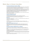
Operation/Reference Guide
Metreau Keypads
™
MET-6N 6-Button Keypad with Navigation
MET-7 7-Button Keypad
MET-13 13-Button Keypad
DAS-MET6SRC 6-Source Audio Keypad
DAS-MET-NUM Numeric Audio Keypad
K e ypa ds
Last Revised: 12/31/2012
AMX Limited Warranty and Disclaimer
This Limited Warranty and Disclaimer extends only to products purchased directly from AMX or an AMX Authorized Partner which
include AMX Dealers, Distributors, VIP’s or other AMX authorized entity.
AMX warrants its products to be free of defects in material and workmanship under normal use for three (3) years from the date of
purchase, with the following exceptions:
•
Electroluminescent and LCD Control Panels are warranted for three (3) years, except for the display and touch overlay components are warranted for a period of one (1) year.
•
Disk drive mechanisms, pan/tilt heads, power supplies, and MX Series products are warranted for a period of one (1) year.
•
AMX lighting products are guaranteed to switch on and off any load that is properly connected to our lighting products, as long
as the AMX lighting products are under warranty. AMX also guarantees the control of dimmable loads that are properly connected to our lighting products. The dimming performance or quality there of is not guaranteed, impart due to the random combinations of dimmers, lamps and ballasts or transformers.
•
AMX software is warranted for a period of ninety (90) days.
•
Batteries and incandescent lamps are not covered under the warranty.
•
AMX AutoPatch Epica, Modula, Modula Series4, Modula CatPro Series and 8Y-3000 product models will be free of defects in
materials and manufacture at the time of sale and will remain in good working order for a period of three (3) years following the
date of the original sales invoice from AMX. The three-year warranty period will be extended to the life of the product (Limited
Lifetime Warranty) if the warranty card is filled out by the dealer and/or end user and returned to AMX so that AMX receives it
within thirty (30) days of the installation of equipment but no later than six (6) months from original AMX sales invoice date. The
life of the product extends until five (5) years after AMX ceases manufacturing the product model. The Limited Lifetime Warranty
applies to products in their original installation only. If a product is moved to a different installation, the Limited Lifetime Warranty
will no longer apply, and the product warranty will instead be the three (3) year Limited Warranty.
All products returned to AMX require a Return Material Authorization (RMA) number. The RMA number is obtained from the AMX
RMA Department. The RMA number must be clearly marked on the outside of each box. The RMA is valid for a 30-day period. After
the 30-day period the RMA will be cancelled. Any shipments received not consistent with the RMA, or after the RMA is cancelled, will
be refused. AMX is not responsible for products returned without a valid RMA number.
AMX is not liable for any damages caused by its products or for the failure of its products to perform. This includes any lost profits, lost
savings, incidental damages, or consequential damages. AMX is not liable for any claim made by a third party or by an AMX Authorized Partner for a third party.
This Limited Warranty does not apply to (a) any AMX product that has been modified, altered or repaired by an unauthorized agent or
improperly transported, stored, installed, used, or maintained; (b) damage caused by acts of nature, including flood, erosion, or earthquake; (c) damage caused by a sustained low or high voltage situation or by a low or high voltage disturbance, including brownouts,
sags, spikes, or power outages; or (d) damage caused by war, vandalism, theft, depletion, or obsolescence.
This limitation of liability applies whether damages are sought, or a claim is made, under this warranty or as a tort claim (including
negligence and strict product liability), a contract claim, or any other claim. This limitation of liability cannot be waived or amended by
any person. This limitation of liability will be effective even if AMX or an authorized representative of AMX has been advised of the
possibility of any such damages. This limitation of liability, however, will not apply to claims for personal injury.
Some states do not allow a limitation of how long an implied warranty last. Some states do not allow the limitation or exclusion of incidental or consequential damages for consumer products. In such states, the limitation or exclusion of the Limited Warranty may not
apply. This Limited Warranty gives the owner specific legal rights. The owner may also have other rights that vary from state to state.
The owner is advised to consult applicable state laws for full determination of rights.
EXCEPT AS EXPRESSLY SET FORTH IN THIS WARRANTY, AMX MAKES NO OTHER WARRANTIES, EXPRESSED OR
IMPLIED, INCLUDING ANY IMPLIED WARRANTIES OF MERCHANTABILITY OR FITNESS FOR A PARTICULAR PURPOSE. AMX
EXPRESSLY DISCLAIMS ALL WARRANTIES NOT STATED IN THIS LIMITED WARRANTY. ANY IMPLIED WARRANTIES THAT
MAY BE IMPOSED BY LAW ARE LIMITED TO THE TERMS OF THIS LIMITED WARRANTY. EXCEPT AS OTHERWISE LIMITED
BY APPLICABLE LAW, AMX RESERVES THE RIGHT TO MODIFY OR DISCONTINUE DESIGNS, SPECIFICATIONS, WARRANTIES, PRICES, AND POLICIES WITHOUT NOTICE.
Table of Contents
Table of Contents
Metreau™ Keypads ............................................................................................1
Overview .................................................................................................................. 1
Metreau Keypads (AxLink Compatible) ........................................................................... 1
Metreau Audio Keypads (SWT Compatible) .................................................................... 1
Overview - Speaker Wire Technology (SWT) ................................................................... 1
MET-6N Metreau 6-Button Keypad with Navigation ................................................ 2
MET-6N Specifications ................................................................................................... 3
Navigation Wheel ..................................................................................................... 3
Pushbuttons 7-11 ............................................................................................................ 3
Navigation Wheel............................................................................................................ 4
MET-7 Metreau 7-Button Keypad ............................................................................. 4
MET-7 Specifications ...................................................................................................... 4
MET-13 Metreau 13-Button Keypad ......................................................................... 5
MET-13 Specifications .................................................................................................... 5
DAS-MET-6SRC Metreau 6-Source Audio Keypad .................................................... 6
DAS-MET-6SRC Specifications ........................................................................................ 6
Pushbuttons 1-6 .............................................................................................................. 7
Navigation Wheel............................................................................................................ 7
DAS-MET-NUM Metreau Numeric Audio Keypad..................................................... 8
DAS-MET-NUM Specifications ........................................................................................ 8
Custom Button Installation .................................................................................9
Overview .................................................................................................................. 9
Removing Buttons .................................................................................................... 9
Button Kits.............................................................................................................. 10
Audio ............................................................................................................................ 10
Residential..................................................................................................................... 10
Commercial ................................................................................................................... 10
Custom Keypads and Buttons ....................................................................................... 11
AxLink Device Addressing ................................................................................13
Overview ................................................................................................................ 13
Device Addressing on MET-6N Keypads ................................................................ 13
Setting The AxLink Device Address ........................................................................ 13
Mounting and Installation .................................................................................15
Overview ................................................................................................................ 15
Mounting Dimensions ............................................................................................. 15
MET-6N, DAS-MET-6SRC .............................................................................................. 15
MET-7............................................................................................................................ 16
Metreau Keypads
i
Table of Contents
MET-13, DAS-MET-NUM ............................................................................................... 17
Mounting Procedures ............................................................................................. 17
Wallbox Mounting ......................................................................................................... 17
Podium Mounting.......................................................................................................... 18
Accent Frame ................................................................................................................ 18
Wiring and Connections ...................................................................................19
Overview ................................................................................................................ 19
AxLink Wiring ......................................................................................................... 19
MET-6SRC, MET-7 and MET-13 Rear Panel Components .............................................. 19
AxLink Wiring Guidelines .............................................................................................. 20
Preparing Captive Wires ............................................................................................... 20
AxLink Data and Power Connections ............................................................................ 20
Using AxLink for Data with an Auxiliary Power Supply ................................................. 21
Orientation of AxLink Connectors ................................................................................. 21
AxLink Status LED ......................................................................................................... 21
SWT Wiring ............................................................................................................. 22
DAS-MET-6SRC and DAS-MET-7 Rear Panel Components ............................................ 22
Cable Type .................................................................................................................... 22
Preparing Captive Wires ............................................................................................... 22
DAS-MET-6SRC - SWT Data and Power Connections .................................................... 22
Tango System Integration Drawings ....................................................................... 24
Tango System Integration Drawing - Using Four-Conductor Speaker Wire .................. 24
Tango System Integration Drawing - Using the Audio Zone Expander ........................ 24
SWT Special Wiring Configurations ........................................................................ 25
Auxiliary Amplifier Configuration .................................................................................. 25
Remote Amplifier Configuration ................................................................................... 25
Two-Wire Configurations – Keypad for Control Only .................................................... 26
Split Zone / Analog Volume Control ............................................................................. 27
Programming The Metreau Keypads ................................................................29
Programming the AxLink Metreau Keypads ........................................................... 29
Button Layouts .............................................................................................................. 29
Programming the Navigation Wheel (MET-6N) ............................................................. 29
Navigation Wheel - Buttons 7-11 .................................................................................. 30
Navigation Wheel - Buttons 12-13 ................................................................................ 30
Navigation Wheel - Level Control.................................................................................. 30
Display Bargraph ........................................................................................................... 30
Supported SEND_LEVELs .............................................................................................. 30
SEND_LEVEL ............................................................................................................................. 30
Supported SEND_COMMANDs..................................................................................... 31
@BRT ......................................................................................................................................... 31
@WBRT ..................................................................................................................................... 31
ii
Metreau Keypads
Table of Contents
BMODE .....................................................................................................................................31
LED Feedback for 2-Position Pushbuttons .................................................................... 32
Sending Firmware to Metreau Keypads (AxLink).................................................... 32
Device Addressing on MET-6N Keypads ....................................................................... 32
Programming the SWT Metreau Keypads............................................................... 33
Basic Keypad Functions - DAS-MET-6SRC ........................................................35
Overview ................................................................................................................ 35
DAS-MET-6SRC - Listening To a CD or DVD .......................................................... 35
Selecting The Source for Playback ................................................................................ 35
Changing Tracks............................................................................................................ 35
Pausing Playback........................................................................................................... 35
Listening To an iPod...................................................................................................... 36
Listening To the Radio .................................................................................................. 36
Adjusting Volume.......................................................................................................... 36
DAS-MET-6SRC - Audio Adjustment Mode ............................................................ 37
Adjusting Bass Level For a Room/Zone ......................................................................... 37
Adjusting Treble Level For a Room/Zone...................................................................... 37
Adjusting Balance For a Room/Zone ............................................................................. 38
Adjusting SRS Settings For a Room/Zone ..................................................................... 38
Turning SRS Off............................................................................................................. 39
DAS-MET-6SRC - Privacy Mode Off/On .................................................................. 39
Turning Privacy Mode Off ............................................................................................. 39
Working With Sources ............................................................................................ 40
DAS-MET-6SRC - Zone Control (On/Off) ................................................................ 40
Turning a Single Zone On/Off ....................................................................................... 40
Turning On a Source In All Zones .................................................................................. 40
Turning Off/On a Source In All Zones .......................................................................... 41
Turning Off All Zones (System OFF) ............................................................................. 41
DAS-MET-6SRC - Zone Control (Dynamic Pause) .................................................... 42
Single Zone Listening To Source ................................................................................... 42
Multiple Zones Listening To The Same Source.............................................................. 42
DAS-MET-6SRC - Using the Navigation Wheel........................................................ 43
Using the Navigation Wheel With the Internal AM/FM Tuner....................................... 43
Advanced Functions - DAS-MET-6SRC ..............................................................47
Overview ................................................................................................................ 47
Direct Access .......................................................................................................... 47
On-Board Tuner - Direct Selection of a Radio Station ................................................... 47
CD Player - Direct Selection of a Disk and Track ........................................................... 48
CD Player - Direct Selection of a Track On the Current Disk......................................... 48
Cable and Satellite - Direct Selection of a Channel ....................................................... 49
Metreau Keypads
iii
Table of Contents
Working With Presets ............................................................................................. 49
Creating A Preset ......................................................................................................... 49
Recalling A Preset ........................................................................................................ 50
Clearing All Presets ...................................................................................................... 51
Working With Favorites .......................................................................................... 51
Creating a Favorite For a Specific Source .................................................................... 51
Clearing Favorites For All Sources In a Specific Zone ................................................... 52
Working With Zone Grouping................................................................................. 52
Adding a Zone To a Group ........................................................................................... 52
Grouping All Zones ...................................................................................................... 53
Un-Grouping All Zones ................................................................................................. 53
Grouping Volume Control ............................................................................................. 54
Working With Alarms.............................................................................................. 54
Setting the System Clock on the Tango Audio Controller............................................. 54
Setting an Alarm In a Zone ........................................................................................... 55
Clearing the Alarm For a Specific Zone ........................................................................ 55
Clearing All Alarms For All Zones ................................................................................. 56
Keypad Lockout ...................................................................................................... 56
Locking a Keypad ......................................................................................................... 56
Unlocking a Keypad ..................................................................................................... 57
Unlocking All Keypads .................................................................................................. 57
Using the NetLinx Module ................................................................................59
Overview ................................................................................................................ 59
Main Page (Initial View) .......................................................................................... 59
Main Pages ............................................................................................................. 60
Location/Device Pages .................................................................................................. 60
Zone Options ................................................................................................................ 61
Change Source .............................................................................................................. 61
Device Control Pages.............................................................................................. 62
Internal Tuner ................................................................................................................ 62
Internal Sirius................................................................................................................. 63
DVD............................................................................................................................... 64
CD ................................................................................................................................. 65
Audio Server ................................................................................................................. 66
Satellite ......................................................................................................................... 67
External Tuner ............................................................................................................... 68
Other............................................................................................................................. 69
Setup Pages ............................................................................................................ 70
Setup - Zones ................................................................................................................ 70
Setup - Alarms ............................................................................................................... 71
iv
Metreau Keypads
Table of Contents
Adding an Alarm ........................................................................................................... 71
Removing an Alarm ....................................................................................................... 73
SWT Troubleshooting .......................................................................................75
Overview ................................................................................................................ 75
Power Connections ................................................................................................. 75
Zone Connection Problems..................................................................................... 76
Dead Zones ................................................................................................................... 76
LED Does Not light ....................................................................................................... 76
Source Connections....................................................................................................... 76
No Keypad Activity................................................................................................. 77
Keypad Lights, No Sound ....................................................................................... 77
Metreau Keypads
v
Table of Contents
vi
Metreau Keypads
Metreau™ Keypads
Metreau™ Keypads
Overview
Metreau keypads are a convenient, versatile, cost-effective option for achieving effortless control of virtually
anything through a NetLinx® control system. Metreau keypads offer easy installation within decora-style wall
plates and sleek styling that complements the NI-3101-SIG Signature Series NetLinx Integrated Controller
and Tango Distributed Audio System.
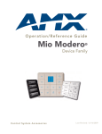
There are two basic variations within the Metreau device family:
Metreau Keypads (AxLink Compatible)
The MET-6N, MET-7 and MET-13 keypads are AxLink-compatible, for use with NetLinx control systems
(FIG. 1).
Metreau keypads (AxLink)
MET-6N
FIG. 1 Metreau keypads
MET-7
MET-13
Metreau Audio Keypads (SWT Compatible)
The DAS-MET-6SRC and DAS-MET-NUM are SWT-compatible, for use with Matrix Audio distribution
systems, via Speaker Wire Technology (SWT). Metreau Audio keypads are compatible with all Matrix
products including Tango and Mi Series Audio Controllers as well as XA Carbon Series Amplifiers (FIG. 2).
Metreau Audio keypads (SWT)
DAS-MET-6SRC
DAS-MET-NUM
FIG. 2 Metreau Audio keypads
In terms of SWT functionality, the Metreau Audio keypads (DAS-MET-6SRC &
DAS-MET-NUM) are a close match to previous versions of Matrix KP and NUM
keypads.
Overview - Speaker Wire Technology (SWT)
Speaker Wire Technology (SWT) allows both data and audio signals to travel over the same four conductor
wire. This remarkable technology removes the need for control wire since the control and audio signals are
shared on the same wire. The reliability and simplicity of this system has been proven for years. AMX Matrix
Audio is the only company that offers a “retrofit solution”, one which allows the replacement of volume
controls with AMX Matrix Audio keypads and Controllers, giving full control over the sources.
Metreau Keypads
1
Metreau™ Keypads
Additionally, the versatility of SWT also allows AMX Matrix Audio products to be connected where the
control wire has been run separately from the speaker cable.
All Metreau keypads are available in three popular colors: White, Black and Light Almond. The following
table lists the keypads in the Metreau family, with descriptions and FG#s for each color.
Metreau Keypads Device Family
Name
Description
Colors/FG#s
MET-6N
Metreau 6-Button Keypad with Navigation • White (FG5794-01-WH)
• Black (FG5794-01-BL)
• Light Almond (FG5794-01-LA)
MET-7
Metreau 7-Button Keypad
• White (FG5794-03-WH)
• Black (FG5794-03-BL)
• Light Almond (FG5794-03-LA)
MET-13
Metreau 13-Button Keypad
• White (FG5794-02-WH)
• Black (FG5794-02-BL)
• Light Almond (FG5794-02-LA)
DAS-MET-6SRC Metreau 6-Source Audio Keypad
• White (FG1122-01-WH)
• Black (FG1122-01-BL)
• Light Almond (FG1122-01-LA)
DAS-MET-NUM
Metreau Numeric Audio Keypad
• White (FG1122-02-WH)
• Black (FG1122-02-BL)
• Light Almond (FG1122-02-LA)
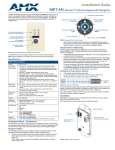
MET-6N Metreau 6-Button Keypad with Navigation
The MET-6N 6-button keypad features source control, visual volume feedback and a navigation wheel that
adjusts volume and provides up, down, left, right and center button options (FIG. 3).
6 pre-printed pushbuttons
(with blue LED indicators)
IR Sensor located here
(supports AMX IR 38kHz)
LED Levels Indicator
1
2
3
4
5
6
9
11
8
Navigation Wheel
Center (push/release)
Center (press/hold)
7
10
CW rotation = 12
CCW rotation = 13
FIG. 3 MET-6N Metreau 6-Button keypad with Navigation (Light Almond shown)
The MET-6N is an AxLink keypad, suitable for use in NetLinx Control Systems.
2
Metreau Keypads
Metreau™ Keypads
MET-6N Specifications
MET-6N Specifications
Power:
12 VDC, 75 mA
Front Panel
Components:
• Pushbuttons - 6 tactile pushbuttons with blue LED indicators that illuminate when
pressed to confirm the source/function was selected and that it is currently being used.
These pre-printed buttons are field-replaceable.
• IR Sensor - Supports standard AMX IR (38 kHz only).
• LED Levels Indicator - set of 7 blue LEDs provide level feedback.
• Navigation Wheel - consists of 5 pushbuttons: 4 directional pushbuttons (Up, Down,
Right, Left), 1 center pushbutton, and bi-directional rotating wheel for channel
adjustments.
• The Navigation wheel itself provides two button functions as well
(rotate CW = button #12, and rotate CCW = button #13, as indicated in FIG. 4).
Rear Panel
Components:
• DIP switch - 8 position mini DIP switch used to set the device address for the keypad
on the AxLink Bus (1-255).
• AxLink connector - 4 pin 3.5mm Phoenix connector for AxLink connection to the
NetLinx Master.
Dimensions (HWD): • Keypad and Mounting Plate: 4.055" x 1.772" x 0.997" (103mm x 45mm x 25.32mm)
• Mounts into standard decora-style wall plates.
Weight:
2.4 oz. (68.04 g)
Operating
Environment:
• Operating Temperature: 32° - 104° F (0°- 40° C).
• Relative Humidity: 5% - 85%, non-condensing.
• Intended for indoor use only.
Certifications:
•
•
•
•
Colors:
• White (FG5794-01-WH)
• Black (FG5794-01-BL)
• Light Almond (FG5794-01-LA)
Optional
Accessories:
• Single Button Kit (FG5794-10)
• Lutron Cairo Wallplates (available in a variety of sizes and colors)
FCC Class B
CE
IEC60950
RoHS
Navigation Wheel
FIG. 4 shows the button layout of the Navigation Wheel:
Directional pushbutton UP
Rotate counter-clockwise
= button #13
9
Directional pushbutton
LEFT
Rotate clockwise
= button #12
7
11
8
10
Directional pushbutton
RIGHT
Center pushbutton
Directional pushbutton DOWN
FIG. 4 Navigation Wheel - button layout
Pushbuttons 7-11
The top, bottom, left, right and center points on the Navigation Wheel are pushbuttons #7, #8, #9, #10 and #11,
and can be programmed like any other AxLink button.
Metreau Keypads
3
Metreau™ Keypads
Navigation Wheel
The Navigation Wheel itself can be rotated clockwise and counterclockwise, and is intended to provide level
control (for example volume or lighting levels).
When rotated clockwise, the Navigation Wheel provides a channel event on button #12.
When rotated counter-clockwise, the Navigation Wheel provides a channel event on button #13.
The light on the Navigation Wheel can be illuminated by activating channel #11.
MET-7 Metreau 7-Button Keypad
The MET-7 offers 7 double-width buttons that can be used as in individual keypad or in conjunction with the
6N and 13-button Metreau keypads (FIG. 3).
7 pre-printed pushbuttons
(with blue LED indicators)
Two-position button
FIG. 5 MET-7 Metreau 7-Button keypad (Light Almond shown)
The MET-7 is an AxLink keypad, suitable for use in NetLinx Control Systems.
MET-7 Specifications
MET-7 Specifications
Power:
12 VDC, 30 mA
Front Panel
Components:
Pushbuttons - 7 tactile pushbuttons with blue LED indicators that illuminate when
pressed to confirm the source/function was selected and that it is currently being used.
These pre-printed buttons are field-replaceable.
The bottom button functions as 2 buttons - there are 2 positions (left and right) that allow
the user to control channel/levels (up/down).
Rear Panel
Components:
• DIP switch - 8-position mini DIP switch used to set the device address for the keypad
on the AxLink Bus (1-255).
• AxLink connector - 4-pin 3.5mm Phoenix connector for AxLink connection to the
NetLinx Master.
Dimensions (HWD): • Keypad and Mounting Plate: 4.055" x 1.772" x 0.818" (103mm x 45mm x 207mm)
• Mounts into standard decora-style wall plates.
4
Weight:
2.4 oz. (68.04 g)
Operating
Environment:
• Operating Temperature: 32° - 104° F (0°- 40° C).
• Relative Humidity: 5% - 85%, non-condensing.
• Intended for indoor use only.
Metreau Keypads
Metreau™ Keypads
MET-7 Specifications (Cont.)
Certifications:
•
•
•
•
FCC Class B
CE
IEC60950
RoHS
Colors:
• White (FG5794-03-WH)
• Black (FG5794-03-BL)
• Light Almond (FG5794-03-LA)
Optional
Accessories:
• Single Button Kit (FG5794-10)
• Double Button Kit (FG5794-11)
• Lutron Cairo Wallplates (available in a variety of sizes and colors)
MET-13 Metreau 13-Button Keypad
The MET-13 offers 13 buttons (12 single-width and 1 double-width) and can be used as in individual keypad
or in conjunction with the 6N and 7-button Metreau keypads (FIG. 3).
13 pre-printed pushbuttons
(with blue LED indicators)
Two-position button
FIG. 6 MET-13 Metreau 13-Button keypad (Light Almond shown)
The MET-13 is an AxLink keypad, suitable for use in NetLinx Control Systems.
MET-13 Specifications
MET-13 Specifications
Power:
12 VDC, 30 mA
Front Panel
Components:
Pushbuttons - 13 tactile pushbuttons with blue LED indicators that illuminate when
pressed to confirm the source/function was selected and that it is currently being used
(12 single-width, 1 double-width). These pre-printed buttons are field-replaceable.
The bottom button functions as 2 buttons - there are 2 positions (left and right) that
allow the user to control channels (up/down).
Rear Panel
Components:
• DIP switch - 8-position mini DIP switch used to set the device address for the keypad
on the AxLink Bus (1-255).
• AxLink connector - 4-pin 3.5mm Phoenix connector for AxLink connection to the
NetLinx Master.
Dimensions (HWD): • Keypad and Mounting Plate: 4.055" x 1.772" x 0.818"
(103mm x 45mm x 207mm)
• Mounts into standard decora-style wall plates.
Weight:
Metreau Keypads
2.4 oz. (68.04 g)
5
Metreau™ Keypads
MET-13 Specifications (Cont.)
Operating
Environment:
• Operating Temperature: 32° - 104° F (0°- 40° C).
• Relative Humidity: 5% - 85%, non-condensing.
• Intended for indoor use only.
Certifications:
•
•
•
•
Colors:
• White (FG5794-02-WH)
• Black (FG5794-02-BL)
• Light Almond (FG5794-02-LA)
Optional
Accessories:
• Single Button Kit (FG5794-10)
• Double Button Kit (FG5794-11)
• Lutron Cairo Wallplates (available in a variety of sizes and colors)
FCC Class B
CE
IEC60950
RoHS
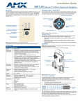
DAS-MET-6SRC Metreau 6-Source Audio Keypad
The DAS-MET-6SRC 6-button keypad (FIG. 3) features source control, visual volume feedback and a
navigation wheel that adjusts volume and provides up, down, left, right and center button options (see the
Basic Keypad Functions - DAS-MET-6SRC section on page 35 for information).
6 pre-printed pushbuttons
(with blue LED indicators)
IR Sensor located here
Volume Level Indicator LEDs
Navigation Wheel
FIG. 7 DAS-MET-6SRC Metreau 6-Source Audio keypad (Light Almond shown)
The DAS-MET-6SRC is a SWT keypad, suitable for use in Matrix Distributed Audio Systems.
DAS-MET-6SRC Specifications
DAS-MET-6SRC Specifications
Power:
12 VDC, 125 mA
Front Panel
Components:
• Pushbuttons - 6 tactile pushbuttons with blue LED indicators that illuminate when the
source is selected, and stay lit until the source is turned off. These pre-printed buttons
are field-replaceable.
• IR Sensor - Works specifically with the MIO-R1-AUDIO remote controller (38 kHz only).
• LED Levels Indicator - set of 7 blue LEDs provide volume level feedback.
• Navigation Wheel - consists of 5 pushbuttons: 4 directional pushbuttons (Up, Down,
Right, Left), 1 center pushbutton, and bi-directional rotating wheel for volume
adjustments.
Note that the center pushbutton is dual-purpose: a push/release provides one function,
while a press/hold provides another.
6
Metreau Keypads
Metreau™ Keypads
DAS-MET-6SRC Specifications (Cont.)
Rear Panel
Components:
Wiring connection - Two 4-pin SWT connectors that provide connection from the Matrix
Audio Controller, and to the speakers.
Dimensions (HWD): • Keypad and Mounting Plate: 4.055" x 1.772" x 0.997"
(103mm x 45mm x 25.32mm)
• Mounts into standard decora-style wall plates.
Weight:
2.4 oz. (68.04 g)
Operating
Environment:
• Operating Temperature: 32° - 104° F (0°- 40° C).
• Relative Humidity: 5% - 85%, non-condensing.
• Intended for indoor use only.
Certifications:
•
•
•
•
Colors:
• White (FG1122-01-WH)
• Black (FG1122-01-BL)
• Light Almond (FG1122-01-LA)
Optional
Accessories:
• Single Button Kit (FG5794-10)
• Lutron Cairo Wallplates (available in a variety of sizes and colors)
FCC Class B
CE
IEC60950
RoHS
Pushbuttons 1-6
The top, bottom, left and right points on the Navigation Wheel are used for source control and can be
programmed to provide any source functionality by learning the applicable IR code.
The center pushbutton is dual-purpose: a push/release on this button provides one function, while a press/hold
provides another. The center pushbutton are also used for source control and can be programmed to provide
any source functionality (again, by learning the applicable IR code).
Navigation Wheel
FIG. 8 shows the button layout of the Navigation Wheel:
Top center pushbutton = Nav UP
Rotate wheel
counter-clockwise to
adjust Volume Down
Left center
pushbutton =
Nav LEFT
Rotate wheel clockwise
to adjust Volume Up
Right center
pushbutton =
Nav RIGHT
Center pushbutton =
Nav Center
Bottom center pushbutton = Nav DOWN
FIG. 8 Navigation Wheel - button layout
The Navigation Wheel can be rotated bi-directionally, and provides volume level control:
Clockwise rotation increases the volume level, counter-clockwise rotation decreases the volume
level.
The range for volume is 0 - 70.
Metreau Keypads
7
Metreau™ Keypads
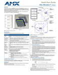
DAS-MET-NUM Metreau Numeric Audio Keypad
The DAS-MET-NUM Metreau numeric keypad (FIG. 9) connects to the Main DAS-MET-6SRC keypad via a
14-pin connector. Used in conjunction with the DAS-MET-6SRC Metreau keypad, it provides direct numeric
access, setting & recalling presets, and access to advanced functionality such as grouping, Setting Favorites,
Alarm, and Keypad lockout functionality (see the Advanced Functions - DAS-MET-6SRC section on page 47
for information).
12 pre-printed pushbuttons
ENTER button
(with LED to
provide feedback)
FIG. 9 DAS-MET-NUM Metreau Numeric Audio keypad (White shown)
The DAS-MET-NUM is a SWT keypad, suitable for use in Matrix Distributed Audio Systems.
DAS-MET-NUM Specifications
DAS-MET-NUM Specifications
Power:
12 VDC, 125 mA
Front Panel
Components:
Pushbuttons - 13 tactile pushbuttons.
Rear Panel
Components:
Wiring connection - One 14-pin connector that provides connection to the main 6 Source
Metreau Keypad (DAS-MET-6SRC).
Dimensions (HWD): • Keypad and Mounting Plate: 4.055" x 1.772" x 0.818"
(103mm x 45mm x 207mm)
• Mounts into standard decora-style wall plates.
8
Weight:
2.4 oz. (68.04 g)
Operating
Environment:
• Operating Temperature: 32° - 104° F (0°- 40° C).
• Relative Humidity: 5% - 85%, non-condensing.
• Intended for indoor use only.
Certifications:
•
•
•
•
Colors:
• White (FG1122-02-WH)
• Black (FG1122-02-BL)
• Light Almond (FG1122-02-LA)
Optional
Accessories:
• Single Button Kit (FG5794-10)
• Double Button Kit (FG5794-11)
• Lutron Cairo Wallplates (available in a variety of sizes and colors)
FCC Class B
CE
IEC60950
RoHS
Metreau Keypads
Custom Button Installation
Custom Button Installation
Overview
With the exception of the DAS-MET-NUM, all Metreau keypads feature field-replaceable pre-printed buttons.
This section describes removing the original set of buttons and replacing them with custom buttons. FIG. 10
provides an exploded view of the keypad assembly.
remove screw
remove screw
Circuit board
remove screw
tabs (2 on each side)
remove screw
Buttons
Metal Mounting Plate
Plastic Faceplate
FIG. 10 Metreau keypads - Exploded view
Removing Buttons
The easiest way to remove and replace buttons on the Metreau keypads is to place the keypad assembly
(FIG. 10) face-down on a flat level surface, so that the buttons stay in position until you are ready to remove
them.
Disconnect the power supply and all wiring connections before removing/replacing
buttons on the Metreau keypads.
Before touching the device, discharge the static electricity from your body by touching
a grounded metal object.
The Faceplate is attached to the Mounting Plate via four plastic tabs (two on each side of the Faceplate, as
shown in FIG. 10). It is not necessary to remove the plastic faceplate from the Mounting Plate in order to
replace buttons.
Metreau Keypads
9
Custom Button Installation
1. On the back of the keypad assembly, remove the four screws that secure the Mounting Plate (with
Faceplate attached) to the Circuit Board.
2. Carefully remove the Circuit Board from the Mounting Plate. Once the Circuit Board is removed from the
Mounting Plate, the buttons are prone to fall out of position. In most cases, there is sufficient friction
within the button mounts to hold them in place on the Circuit Board. However, take care at this point not
to accidentally drop the buttons or any other part of the keypad assembly.
3. Gently lift each button off of their mounting posts on the Circuit Board.
4. Select the location of the custom buttons and gently snap them into place on the Circuit Board.
Be sure to note the orientation of the LED window on each button, to avoid accidentally mounting them
upside down.
5. Carefully insert the Circuit Board (with new buttons mounted) to the Mounting Plate.
Take care to align the buttons properly with their respective holes in the Faceplate.
6. Replace and secure the four screws on the back of the Circuit Board. (FIG. 11).
Circuit board
Plastic Faceplate
Metal Mounting Plate
FIG. 11 Keypad assembly
Button Kits
Three different button kits are available for Metreau keypads, to accommodate most installations:
Audio
SIRIUS, XM, IPOD, MP3, CD2, AUX2, DVD2, PC, FM.
Residential
LIGHTS, FAN, SHADES, HVAC+, HVAC -, UP, DOWN, TV.
Commercial
DISP, PROJ, VC, AC, HVAC, LIGHTS, SCREEN.
10
Metreau Keypads
Custom Button Installation
Custom Keypads and Buttons
If a requested keypad needs functions not offered in the standard Button Kits, a custom keypad may be built
with the AMX Metreau Keypad Preview (FIG. 12), available at www.amx.com. This tool allows custom
arrangement of default or custom button arrangements, creation of custom button text, previews of keypad type
and color, and printouts of final keypad layouts and parts lists.
FIG. 12 Metreau Keypad Preview
Metreau Keypads
11
Custom Button Installation
12
Metreau Keypads
AxLink Device Addressing
AxLink Device Addressing
Overview
Metreau Keypads used in NetLinx applications require a unique numeric AxLink device address of 1-255.
Consider specifying the device address for each keypad before final installation.
AxLink device addressing applies only to the MET-6SRC, MET-7 and MET-13
keypads. Metreau Audio Keypads (DAS-MET-6SRC and DAS-MET-13) do not
require device addressing.
Device Addressing on MET-6N Keypads
The MET-6N uses two AxLink devices addresses - one for the Keypad itself, and a second one for
the IR Receiver.
The device address of the IR Receiver is auto-assigned to be one number higher than the device
address of the Keypad itself (to which the firmware is uploaded).
The MET-6N will appear as two devices in the Devices frame, because it’s built-in IR Receiver is
recognized as a separate online device.
Firmware is uploaded to the device address of the Keypad (not the IR Receiver).
For example, if the MET-6N is set to device address 127, then the IR Receiver on that
MET-6N will appear as device number 128. Firmware must be sent to the keypad, not the IR
Receiver (in this example, device 127).
Setting The AxLink Device Address
AxLink-enabled Metreau keypads (MET-6N, MET-7 and MET-13) use an 8-position mini-DIP switch to
specify a unique device address for each keypad in a NetLinx Control System (see FIG. 13).
DIP Switch
DIP Switch
DIP Switch
MET-6N
MET-7
MET-13
FIG. 13 DIP Switch and SWT Jumper locations
Before touching the device, discharge the static electricity from your body by touching
a grounded metal object.
Metreau Keypads
13
AxLink Device Addressing
1. If connected, disconnect the power supply.
2. Locate the 8-position mini-DIP switch on the rear panel.
3. Set the DIP switch according to the values shown below.
Switch
1 2 3 4 5
6
7
8
Value
1 2 4 8 16 32 64 128
The device number is set by the total value of DIP switch positions that are in the ON position. Note that
the ON position is indicated on the DIP Switch.
As an example, the DIP switch in FIG. 14 defines AXlink device number 129 (1+128=129).
FIG. 14 8-position mini-DIP Switch
If you later change the device number, remove and reconnect the power connector to enter the new device
number into memory.
AMX has created the "Dip Switch2" software application to assist in calculating dip
switch position values. Download the (free) program Dip Switch2 from
www.amx.com.
14
Metreau Keypads
Mounting and Installation
Mounting and Installation
Overview
Metreau keypads are designed to install into standard U.S. decora-style wall plates and boxes (wallboxes not
included).
Before touching the device, discharge the static electricity from your body by touching
a grounded metal object.
Mounting Dimensions
MET-6N, DAS-MET-6SRC
FIG. 15 provides detailed dimensions for the MET-6N and DAS-MET-6SRC keypads.
FIG. 15 MET-6N and DAS-MET-6SRC Mounting Dimensions
Metreau Keypads
15
Mounting and Installation
MET-7
FIG. 16 provides detailed dimensions for the MET-7 keypads.
FIG. 16 MET-7 Mounting Dimensions
16
Metreau Keypads
Mounting and Installation
MET-13, DAS-MET-NUM
FIG. 17 provides detailed dimensions for the MET-13 and DAS-MET-NUM keypads.
FIG. 17 MET-13 and DAS-MET-NUM Mounting Dimensions
Mounting Procedures
AMX recommends mounting Metreau keypads in standard U.S.-style decora wallboxes:
Conduit box should meet NEC specs (section 370)
Minimum internal clearance of (HWD) 2-5/8" x 1-3/4" x 1-5/8".
Wallbox Mounting
1. Use the cutout dimension for the wallbox to cutout the install surface.
2. Connect the AxLink connector (or SWT cable connectors) to the rear of the keypad.
3. Place the Mounting Plate on the wallbox; align the screw holes with the mounting holes and fasten the
Mounting Plate to the wallbox using the screws supplied.
Do not overtighten the screws when mounting the Mounting Frame. The device
should be flush with mounting surface.
Metreau Keypads
17
Mounting and Installation
Podium Mounting
1. Use the cutout dimension for the wallbox to cutout the Mounting Frame install surface for the keypad
2. Confirm that the terminal end of the AxLink cable is disconnected, and not receiving power.
3. Connect the AxLink power supply. The connector passes through the center of the Mounting Frame and
connects to the board.
4. With the Mounting Frame resting in the cutout area, drill the mounting holes into the flat surface.
Do not overtighten the screws when mounting the Mounting Frame. The device
should be flush with mounting surface.
Accent Frame
While the Metreau device family does fit into many International wallboxes, it may be necessary to utilize the
optional Accent Frame to completely cover the wallbox.
To install the keypad with the optional Accent Frame:
1. Use the cutout dimension for the wallbox to cut out the install surface for the keypad.
2. Place the Accent Frame on the wallbox; align the screw holes with the mounting holes on the wallplate.
Fasten the wallplate to the wallbox.
Based on the extensive number of international wallboxes it is not pragmatic to ship every possible screw
that could be used. Please use the screws appropriate for your specific wallbox.
Do not overtighten the screws when mounting the Mounting Frame. The device
should be flush with mounting surface.
3. Confirm that the terminal end of the AxLink cable is disconnected, and not receiving power.
4. Connect the power supply. The connector passes through the center of the Mounting Frame and connects
to the board.
5. Place the Mounting Frame on the Accent Frame; align the screw holes with the mounting holes and fasten
the Mounting Frame to the wallplate. The Accent Frame is shipped with two #6-32 x .187 long flat head
screws (80-131); these are used to attach the keypad to the accent frames.
18
Metreau Keypads
Wiring and Connections
Wiring and Connections
Overview
Metreau keypads support both AxLink and SWT wiring configurations. Each is described in the following
sub-sections. For information on AxLink vs. SWT device addressing, refer to the AxLink Device
Addressing section on page 13.
Before touching the device, discharge the static electricity from your body by touching
a grounded metal object.
AxLink Wiring
In AxLink mode, Metreau keypads use a standard four-pin captive-wire AxLink connector for power and data.
If using power from AxLink, disconnect the wiring from the control system before
wiring the Metreau keypad.
Do not connect power to the keypads until the wiring is complete.
MET-6SRC, MET-7 and MET-13 Rear Panel Components
Before touching the device, discharge the static electricity from your body by touching
a grounded metal object.
FIG. 18 shows the basic rear components of the AxLink (MET-6N, MET-7 and MET-13) keypads:
Mounting Plate
not used
Device Address
DIP Switch
AxLink connector
(from NetLinx Controller)
not used
not used
FIG. 18 MET-6SRC, MET-7 and MET-13 - Rear Components
Metreau Keypads
19
Wiring and Connections
AxLink Wiring Guidelines
Metreau keypads require 12 VDC power to operate properly. The necessary power is supplied via the AxLink
cable. The maximum AxLink wiring distance is determined by power consumption, supplied voltage, and the
wire gauge used for the cable.
The following table lists wire sizes and the maximum lengths allowable based on the maximum power
consumption rating of 170 mA.
Wiring Guidelines at 170 mA
Wire Size Maximum Wiring Length
18 AWG
690.42 feet (210.43 m)
20 AWG
436.80 feet (133.13 m)
22 AWG
272.33 feet (83.00 m)
24 AWG
171.66 feet (52.32 m)
The maximum wiring lengths for using AxLink power are based on a minimum of 13.5 volts available.
Preparing Captive Wires
You will need a wire stripper, and flat-blade screwdriver to prepare and connect the captive wires.
1. Strip 0.25 inch (6.35 mm) of wire insulation off all wires.
2. Insert each wire into the appropriate opening on the connector according to the wiring diagrams and
connector types described in this section.
3. Turn the flat-head screws clockwise to secure the wires in the connector.
Do not over-torque the screws; doing so can bend the seating pins and damage the
connector.
AxLink Data and Power Connections
Connect the NetLinx Controller’s AxLink connector to the AxLink connector on the rear panel of the Metreau
keypad for data and 12 VDC power as shown in FIG. 19.
PWR (+)
PWR (+)
AXP
AXP
AXM
AXM
GND (-)
NetLinx Controller
GND (-)
Metreau keypad (or other AxLink device)
FIG. 19 AxLink straight-thru wiring
20
Metreau Keypads
Wiring and Connections
Using AxLink for Data with an Auxiliary Power Supply
Use an auxiliary 12 VDC power supply when the distance between the controller and server exceeds the limits
described in the AxLink Wiring Guidelines. Connect only the GND (-) wire on the AxLink connector when
using an auxiliary 12 VDC power supply.
Connect the NetLinx Controller’s AxLink connector to the AxLink connector on the rear panel of the Metreau
keypad, as shown in FIG. 20.
12 VDC power supply
PWR (+)
GND (-)
PWR (+)
PWR (+)
AXP
AXP
AXM
AXM
GND (-)
GND (-)
NetLinx Controller
FIG. 20 AxLink and 12 VDC power supply wiring diagram
Metreau keypad
If you are not using power from AxLink, disconnect the wiring from the controller
before wiring the Metreau keypad. Make sure the auxiliary power supply’s PWR (+) is
not connected to the controller’s AxLink connector.
Orientation of AxLink Connectors
Note the orientation of the two AxLink 4-pin connectors; be sure to maintain straight-thru wiring as shown in
the diagrams, relative to the connectors (FIG. 21):
PWR (+)
AXP
AXM
GND (-)
NetLinx Controller
FIG. 21 AxLink wiring - orientation of the AxLink connectors
Metreau Keypad (or other AxLink device)
AxLink Status LED
The AxLink Status LED (located next to the AxLink connector), lights to indicate AxLink power/data status as
follows:
AxLink LED Status
• 1 blink per second:
Indicates power is active and AxLink communication is working.
• Full On:
Indicates the following conditions:
• There is no AxLink control or activity, but power is On.
• The Axcess program is not loaded.
If the LED is on and not flashing, disconnect the AxLink connector and recheck all AxLink connections.
Then, reconnect the AxLink connector to the panel and verify the LED is flashing once per second.
Metreau Keypads
21
Wiring and Connections
SWT Wiring
DAS-MET-6SRC and DAS-MET-7 Rear Panel Components
Before touching the device, discharge the static electricity from your body by touching
a grounded metal object.
FIG. 22 shows the basic rear components of the SWT (DAS-MET-6SRC and DAS-MET-NUM) keypads:
not used
14-pin connector
(To DAS-MET-NUM)
14-pin connector
(From DAS-MET-NUM)
SWT connector
(To speakers)
SWT connector
(from Matrix Controller)
DAS-MET-6SRC
DAS-MET-NUM
FIG. 22 DAS-MET-6SRC and DAS-MET-NUM - Rear Components
Cable Type
SWT wiring involves connecting the Mi-Series Controller, Metreau keypads, and speakers.
The Mi-Series Controller and Metreau keypads are cabled using standard four-conductor speaker cable
originating at the Controller, passing through the keypad, and terminating at the speaker location.
AMX recommends using a bundled four-conductor 16-gauge stranded copper wire in a single continuous run.
Preparing Captive Wires
SWT wiring utilizes four-color "snap connectors" to secure the wires (no screws). You will need a wire
stripper to prepare and connect the captive wires.
1. Strip 0.25 inch (6.35 mm) of wire insulation off all wires.
2. Insert each wire into the appropriate opening on the connector according to the wiring diagrams and
connector types described in this section.
DAS-MET-6SRC - SWT Data and Power Connections
1. Connect the Matrix Controller’s Zone Output connector to the four-pin connector on the rear panel of the
Metreau keypad labeled TO CONTROLLER for data and 12 VDC power.
2. Connect the other four-pin connector on the keypad labeled TO SPEAKERS to the SWT speakers as
shown in FIG. 19.
22
Metreau Keypads
Wiring and Connections
Speakers
LL+
TO CONTROLLER
R-
TO SPEAKERS
R+
R
R
G
G
D
D
L
L
Mi-Series Controller
Delta Series Controller
Carbon XA Series Amplifier
SWT connectors on
Metreau keypad
FIG. 23 SWT wiring
DAS-MET-NUM - Connecting to the Main DAS-MET-6SRC Keypad
The DAS-MET-NUM Metreau numeric keypad connects to the main DAS-MET-6SRC keypad via a
14-pin connector, as indicated in FIG. 24:
Pin #1
14-pin connector
Pin #1
14-pin connector
DAS-MET-6SRC
DAS-MET-NUM
FIG. 24 DAS-MET-NUM connected to main DAS-MET-6SRC keypad
The red line on the cable indicates Pin #1.
The cable cannot be twisted, it must be straight across (Pin #1 to Pin #1).
Metreau Keypads
23
Wiring and Connections
Tango System Integration Drawings
Tango System Integration Drawing - Using Four-Conductor Speaker Wire
IR OUT
LINE IN
Tango
Controller
Shared 4-conductor speaker wire
FIG. 25 System Integration Drawing Using Four-Conductor Speaker Wire
Tango System Integration Drawing - Using the Audio Zone Expander
IR OUT
LINE IN
Zones 1-8
Tango
Controller
LINE IN
RJ11
Tango Audio Zone Expander
Shared 4-conductor speaker wire
FIG. 26 System Integration Drawing Using the Audio Zone Expander
24
Metreau Keypads
Wiring and Connections
SWT Special Wiring Configurations
Auxiliary Amplifier Configuration
In some cases you may require more power for a given zone than the Matrix Controller can provide. You may
purchase a DAS-LLC to provide a line level output to incorporate a larger external amplifier, or you can make
your own line level converter.
FIG. 27 shows the construction of a simple circuit of discrete components to reduce the "speaker level" output
of the Matrix Controller to “line level" so that it can drive an auxiliary amplifier.
Matrix Controller
Zone Output Terminal Connector
DATA
Ground (-)
Right Speaker
Left Speaker
R1, R3 = 47K 1/4 Watt Resistor
R2, R4 = 10K 1/4 Watt Resistor
R1
R3
Left RCA Jack to Amp
Right RCA Jack to AMP
R2
R4
Left Speaker
Metreau keypad
Terminator
Right Speaker
FIG. 27 Auxiliary Amplifier Configuration
This amplifier would typically be installed at the equipment rack (head end).
Remote Amplifier Configuration
In some cases, where the distance between the Matrix Controller and the zone is unusually long, it is
sometimes desirable to have a remote amplifier at the zone end. You may install a DAS-LLC to accomplish
this task or you may build your own. FIG. 28 shows the construction of a simple circuit of discrete components
to reduce the Matrix Controller output to “line- level” so that it can be fed into an auxiliary amplifier.
Data
Ground
Left Audio
Right Audio
Matrix Controller
Zone Output Terminal Connector
R1
R3
R2
R4
Left RCA Jack to Amp
R1, R3 = 47K 1/4 Watt Resistor
R2, R4 = 10K 1/4 Watt Resistor
Right RCA Jack to AMP
FIG. 28 Remote Amplifier Configuration
Metreau Keypads
25
Wiring and Connections
Two-Wire Configurations – Keypad for Control Only
In some retrofit configurations it is not feasible or possible to re-route the speaker cable through the keypad. In
cases such as this, it is possible to run a separate cable pair (CAT-3 / CAT-5 / Twisted Pair) cable from the
Matrix Controller to the keypad for control purposes.
When using CAT3/CAT5 over long runs, it is recommended to "double-up" the control wires (only 2
conductors are required, and there are 4-8 wires available).
FIG. 29 shows the connections of the control signal path to the keypad, and the speaker connections to the
Matrix Controller.
L D G
Cat5/Cat3/Twisted Pair
R
Zone Output Connector
(on Matrix Controller)
Metreau keypad
+
Left
-
+
Right
FIG. 29 2 Wire Configurations - keypad for Control Only
26
Metreau Keypads
Wiring and Connections
Split Zone / Analog Volume Control
In cases of split zones where more than one set of speakers are driven from the same keypad, it is sometimes
desirable to place a volume control in the split zone. FIG. 30 shows the connections to a remote zone, and
“Autoformer” volume control device.
Zone Output Connector
(on Matrix Controller)
L D G R
Volume Control
Metreau keypad
Right
Right
Left
Left
FIG. 30 Split Zone / Analog Volume control (Option 2) one keypad
Ensure the impedance setting doesn't fall below 4 Ohms.
If you are installing 2 pairs of speakers in a zone and the speakers are 8 Ohms, it is not necessary to
use an impedance matching autoformer type volume control. A standard stereo volume control will
perform properly. The impedance will be approximately 4 Ohms.
If you are using an impedance matching volume control with 2 pairs of speakers set the impedance
matching to the 2X setting.
It is not recommended to install more than 2 pair of speakers per zone.
Metreau Keypads
27
Wiring and Connections
28
Metreau Keypads
Programming The Metreau Keypads
Programming The Metreau Keypads
Programming the AxLink Metreau Keypads
Button Layouts
The following illustrations indicate the button numbers for each of the AxLink Metreau Keypads
(MET-6N, MET-7 and MET-13):
1
3
5
1
1
2
4
2
3
4
6
3
5
6
4
7
8
5
9
10
2
13
7
9
11
12
6
10
8
7
MET-6N
Center pushbutton = button #11
dual function:
(push/release, press/hold)
rotate Navigation Wheel
clockwise = button #12
8
MET-7
Bottom pushbutton is a
two-position Pushbutton:
left side = button #7
right side = button #8
11
12
13
14
MET-13
Bottom pushbutton is a
two-position Pushbutton:
left side = button #13
right side = button #14
rotate Navigation Wheel
counter-clockwise = button #13
rotate Navigation Wheel
CW/CCW = level #2
FIG. 31 Button Layout - MET-6N, MET-7 and MET-13
Programming the Navigation Wheel (MET-6N)
The Navigation Wheel has multiple programming functions. The device has four buttons mounted underneath
the wheel, assigned as top, bottom, left, right, and center. These buttons are fully programmable. The wheel
itself is also fully programmable.
The Navigation Wheel on the MET-6N can be treated from a NetLinx programming perspective as 5 distinct
pushbuttons plus Channel up and down. The button layout for the Navigation Wheel is indicated below
(FIG. 32).
Metreau Keypads
29
Programming The Metreau Keypads
Rotate the Navigation Wheel
counter-clockwise for
button event #13
Rotate the Navigation Wheel
clockwise for
button event #12
7
9
11
10
8
Center = button #11
dual function:
push/release,
and press and hold
Rotate bi-directionally for level
events on Level #2
FIG. 32 Navigation Wheel - button layout
Navigation Wheel - Buttons 7-11
The top, bottom, left, right and center points on the Navigation Wheel are pushbuttons that provide events on
Channels #7, #8, #9, #10 and #11, and can be programmed like any other AxLink button.
Navigation Wheel - Buttons 12-13
The Navigation Wheel itself can be rotated clockwise and counterclockwise, and is intended to provide level
control (for example volume or lighting levels).
When rotated clockwise, the Navigation Wheel provides events on Channel #12.
When rotated counter-clockwise, the Navigation Wheel provides events on Channel #13.
When rotated (clockwise/counter-clockwise), the Navigation wheel provides level events on Level
#2.
Navigation Wheel - Level Control
In addition to generating button events, a rotation of the wheel causes a level change on Level #2:
Clockwise rotations increase the level
Counter-clockwise rotations decrease the level.
Example code is provided below:
LEVEL_EVENT[dvMetreau,2]
{
volume = level.value
SEND_STRING 0, “’Volume is now: ‘, ITOA(volume)”
}
Display Bargraph
The display bargraph consists of 7 LEDs and is controlled via Level #1. Sending a level will update the LEDs
on the display bargraph.
Example code is provided below:
SEND_LEVEL dvMetreau,1,200
Supported SEND_LEVELs
MET-6N keypads support a SEND_LEVEL on Level #1. This is used to adjust the LED bargraph display on
the keypad.
SEND_LEVELs
SEND_LEVEL
Adjusts the LED bargraph display on the keypad.
Syntax:
SEND_LEVEL <device address>,1,<level>
Variables:
• level = LED bargraph display (range = 0 - 255).
30
Metreau Keypads
Programming The Metreau Keypads
Supported SEND_COMMANDs
The AxLink-enabled Metreau keypads (MET-6N, MET-7 and MET-13) support a number of NetLinx
SEND_COMMANDs, described in the following section. To use these commands, establish a Telnet session
from the PC to the NetLinx master.
All text is based on a Unicode index.
SEND_COMMANDs
@BRT
Set Brightness level for all LEDs (pushbuttons and levels indicator bar), for
both On and Off states.
Syntax:
@BRT-<on brightness (0-32)>,<off brightness (0-32)>
Variables:
• on brightness = LED On brightness and can range from 0 (off) to 32 (max).
• off brightness = LED Off level brightness and can range from 0 (off) to 32
(max).
Example:
SEND_COMMAND keypad,'@BRT-32,0'
Sets the LEDs to max brightness in the On state (32), and minimum
brightness (no illumination) in the Off state (0).
@WBRT
Set Brightness level for Navigation Wheel LED, for both On and Off states.
Syntax:
‘@WBRT-<on brightness (0-32)>,<off brightness (0-32)>’
Variables:
• on brightness = Scroll Wheel LED on brightness and can range from 0 (off) to
32 (max)
• off brightness = Scroll Wheel LED off brightness and can range from 0 (off) to
32 (max)
Example:
SEND_COMMAND keypad,'@WBRT-32,0'
Sets the Navigation Wheel LED to max brightness in the On state (32), and
minimum brightness (no illumination) in the Off state (0).
BMODE
Sets the bargraph mode:
Syntax:
'BMODE-<bargraph mode 0-9>'
Sets the specified bargraph to operate in one of the following modes:
0 = (default) normal bar mode
1 = normal dot mode (only one peak LED on at a time)
2 = special bar mode (a level of 1-32 still has first LED on)
3 = special dot mode (a level of 1-32 still has first LED on)
4 = inverse normal bar mode
5 = inverse normal dot mode
6 = inverse special bar mode
7 = inverse special dot mode
8 = individual element, discrete mode
9 = inverse individual element, discrete mode
Example:
SEND_COMMAND keypad,'BMODE-0'
Sets the bargraph mode to default mode.
Metreau Keypads
31
Programming The Metreau Keypads
LED Feedback for 2-Position Pushbuttons
The MET-7 and MET-13 Keypads feature a 2-Position pushbutton at the bottom of the button layout (FIG. 33).
It can be used either as a single button (in which case it functions just like the other buttons), or it can be used
as a 2-position button. In many cases, this button is used as a 2-Position button to provide ramp up/down
control, for volume, light levels, etc.
On the MET-7, the 2-Position button utilizes button numbers 7 (left-side) and 8 (right-side).
On the MET-13, the 2-Position button utilizes button numbers 13 (left-side) and 14 (right-side).
MET-7
MET-13
Button #7
Button #8
Button #13
Button #14
FIG. 33 MET-7 and MET-13 with 2-Position Button
Only the left button provides LED feedback.
In order to achieve LED feedback on the right button, feedback must be toggled on the left button
Sending Firmware to Metreau Keypads (AxLink)
The Firmware on the AxLink-enabled Metreau keypads (MET-6N, MET-7 and MET-13) can be updated via
the NetLinx Studio2 application.
Device Addressing on MET-6N Keypads
The MET-6N uses two AxLink devices addresses - one for the Keypad itself, and a second one for
the IR Receiver.
The device address of the IR Receiver is auto-assigned to be one number higher than the device
address of the Keypad itself (to which the firmware is uploaded).
The MET-6N will appear as two devices in the Devices frame, because it’s built-in IR Receiver is
recognized as a separate online device.
Firmware is uploaded to the device address of the Keypad (not the IR Receiver).
For example, if the MET-6N is set to device address 127, then the IR Receiver on that
MET-6N will appear as device number 128. Firmware must be sent to the keypad, not the IR
Receiver (in this example, device 127).
Refer to the NetLinx Studio 2 online help for additional details on firmware transfers.
NetLinx Studio 2 is available for free download from www.amx.com.
1. Open NetLinx Studio2.
2. Go to Tools > Firmware Transfers > Send to Axcess Device... This opens the Send to Axcess Dialog
Window.
32
Metreau Keypads
Programming The Metreau Keypads
FIG. 34 Send to Axcess Dialog Window
3. Browse to the location of the firmware file.
4. Select the file within the Files frame.
5. Click Query for Devices.
6. Select the Metreau keypad within the Devices frame.
The MET-6N will appear as two devices in the Devices frame, because it’s built-in IR Receiver, is
recognized as a separate online device.
The Device Address of the IR Receiver is always one number higher than the device number of the
keypad itself (to which the firmware is uploaded).
For example, if the MET-6N is set to device number 127, then the IR Receiver on that MET-6N will
appear as device number 128. Firmware must be sent to the keypad, not the IR Receiver (in this example,
device 127).
7. Click Send and then Close.
8. Upon confirmation of a successful send, you can exit NetLinx Studio2.
Programming the SWT Metreau Keypads
SWT-only Metreau keypads (DAS-MET-6SRC and DAS-MET-NUM) are configured via options that are
accessible through the Tango Audio Controller.
Refer to the Tango Audio Controller Operation / Reference Guide (available from www.amx.com) for details.
Metreau Keypads
33
Programming The Metreau Keypads
34
Metreau Keypads
Basic Keypad Functions - DAS-MET-6SRC
Basic Keypad Functions - DAS-MET-6SRC
Overview
Metreau Keypads are pre-configured to provide many common functions. The DAS-MET-6SRC provides
basic keypad functionality, including Source Control (selecting source, initiating and pausing playback),
Volume control (Up/Down), Zone control (On/Off), and audio (Bass/Treble/Balance/SRS Mode) adjustment.
The SWT Metreau Keypads function essentially the same as previous versions SWT
keypads.
The standard configuration for the Audio (SWT) 6-Source Keypad (DAS-MET-6SRC) is described below.
Note that while the functionality described here is fixed for the SWT Keypads, the AxLink Keypads can be
customized, just like any other AxLink keypad.
DAS-MET-6SRC - Listening To a CD or DVD
Press a Source button
to listen to the most
recent selection
Press Source button
again to pause playback
Click a Radio (AM, FM,
XM or SIRIUS) button
to listen to the most
recent station
Level Indicator LEDs
Press left side of
Navigation wheel
for previous track
Press right side of
Navigation wheel
for next track
Rotate wheel to adjust volume
FIG. 35 Metreau Audio keypads
Selecting The Source for Playback
Press the source button (i.e. "CD" or "DVD") on the room/zone keypad to listen to the most recent selection.
If the Source is off the system will turn it on.
If the Source is stopped the system will initiate Play.
If the Source has been paused or muted, the system will un-pause / un-mute it.
Changing Tracks
Press the left and right sides of the Navigation Wheel to change tracks.
Press the button in the center of the Navigation Wheel to select a track and initiate playback.
Pausing Playback
To Pause playback, press the button of the source that is currently playing (indicated by an active LED).
The CD/DVD is only paused if there are no other zones listening to that source. If no other zones
are listening to that source it will be paused.
If the source remains paused for greater than 10 minutes, the Controller will send a POWER OFF
command to the source.
Metreau Keypads
35
Basic Keypad Functions - DAS-MET-6SRC
Listening To an iPod
Dock the iPod in the docking station connected to the Tango Audio Controller, and press the iPod button on the
room/zone keypad to listen to the most recent selection.
The UP, DOWN, LEFT, RIGHT, Centre PRESS and Centre HOLD buttons are programmed by the installer,
based on what the individual dock with remote can do. For example, UP/RIGHT could both be programmed to
be Next track, DOWN/LEFT could both be programmed to be to be Previous track, and Centre could be
programmed to be Play/Pause.
Listening To the Radio
Press the AM, FM, SIRIUS or XM button on the room/zone keypad to listen to the most recent
station.
Select a new station by pressing a custom-programmed button.
The UP, DOWN, LEFT, RIGHT, Centre PRESS and Centre HOLD buttons are programmed by the installer,
however, the standard configuration for the AM/FM Tuner, and for the SIRIUS/XM Tuner is as follows:
AM/FM Tuner on a 6-source keypad:
UP/DOWN = Seek Up/Down
LEFT/RIGHT = Prev/Next Preset
Centre Press = Toggle AM/FM
Centre Hold = Toggle Stereo/Mono
SIRIUS/XM Tuner on a 6-source keypad:
UP/DOWN = Channel UP/DOWN
LEFT/RIGHT = Category Next/Prev
Centre = Select
Centre Hold = Menu
On a Numeric keypad:
Select a new station by pressing the station’s call numbers on the DAS-MET-NUM Numeric
keypad.
Adjusting Volume
The Navigation Wheel can be rotated bi-directionally, and provides volume level control.
Clockwise rotation increases the volume level, counter-clockwise rotation decreases the volume
level.
When the volume is increased/decreased, the 7 LEDs on the KP will increase/decrease accordingly.
Volume is changed based on angle rotation. Each quarter turn is approximately +/- 3db. The range
for Volume is 0-70.
36
Metreau Keypads
Basic Keypad Functions - DAS-MET-6SRC
DAS-MET-6SRC - Audio Adjustment Mode
1 - Bass Level adjust
2 - Treble Level adjust
3 - Balance adjust
4 - SRS Settings
Press bottom two buttons
simultaneously for 4
seconds to enter Audio
Adjustment Mode
Current level setting
indicated by LEDs
Press center (Select) button
to accept changes
Rotate wheel to adjust
the currently selected
audio mode
FIG. 36 DAS-MET-6SRC
On a 6-source keypad, press and hold the bottom two Source buttons simultaneously for four seconds to set or
adjust Bass, Treble, Balance and SRS Mode settings in that room/zone.
Adjusting Bass Level For a Room/Zone
When the bottom two Source buttons are pressed simultaneously for four seconds, the first adjustment is for
Bass Level:
The top-left LED will blink to indicate that Bass Level Adjustment mode is active (FIG. 37).
Top-left LED blinks to indicate
Bass Level Adjust mode
Center LED (LED #4) indicates FLAT
FIG. 37 Bass Level Adjust Mode
Rotate the Navigation Wheel to adjust the bass level up (clockwise) or down (counter-clockwise).
Bass adjustments are provided in +/- 1dB steps, from -10dB (min) to +10dB (max).
The bass level is indicated in the LED display: Flat = center LED (#4) lit.
Press and hold the center (Select) pushbutton on the Navigation Wheel for 3 seconds to return to the
default Bass Level setting.
Press the center (Select) pushbutton on the Navigation Wheel to set the current bass level, and proceed to
Treble Adjustment mode.
Adjusting Treble Level For a Room/Zone
When the Bass Level is set (via the Select button - see above), the next adjustment is for Treble Level:
The top-right LED will blink to indicate that Treble Adjustment mode is active (FIG. 38).
Rotate the Navigation Wheel to adjust the treble level up (clockwise) or down (counter-clockwise).
Metreau Keypads
37
Basic Keypad Functions - DAS-MET-6SRC
Top-right LED blinks to indicate
Treble Level Adjust mode
Center LED (LED #4) indicates FLAT
FIG. 38 Treble Level Adjust Mode
Treble adjustments are provided in +/- 1dB steps, from -10dB (min) to +10dB (max).
The treble level is indicated in the LED display: Flat = center LED (#4) lit.
Press and hold the center (Select) pushbutton on the Navigation Wheel for 3 seconds to return to the
default Treble Level setting.
Press the center (Select) pushbutton on the Navigation Wheel to set the current treble level, and proceed to
Balance Adjustment mode.
Adjusting Balance For a Room/Zone
When the Treble Level is set (via the Select button - see above), the next adjustment is for Balance Adjust:
The middle-row left LED will blink to indicate that Balance Adjust mode is active (FIG. 39).
Middle-left LED blinks to indicate
Balance Adjust mode
Center LED (LED #4) indicates FLAT
FIG. 39 Balance Adjust Mode
Rotate the Navigation Wheel to adjust the balance right (clockwise) or left (counter-clockwise).
The balance setting is indicated in the LED display: Flat = center LED (#4) lit.
Press and hold the center (Select) pushbutton on the Navigation Wheel for 3 seconds to return to the
default Balance setting.
Press the center (Select) pushbutton on the Navigation Wheel to set the current balance settings, and proceed
to SRS Adjustment mode.
Adjusting SRS Settings For a Room/Zone
When the Balance setting is set (via the Select button - see above), the next adjustment is for SRS Adjust:
The second-row right LED will blink to indicate that SRS Adjust mode is active (FIG. 40).
Rotate the Navigation Wheel to select the desired SRS mode.
38
Metreau Keypads
Basic Keypad Functions - DAS-MET-6SRC
Middle-right LED blinks to indicate
SRS Adjust mode
FIG. 40 SRS Adjust Mode
Press the center (Select) pushbutton on the Navigation Wheel to set the current SRS settings, and proceed to
LED "ON" Brightness Adjust mode.
Turning SRS Off
Press and hold the Center Navigation button while in SRS mode.
DAS-MET-6SRC - Privacy Mode Off/On
When Privacy Mode is engaged, the room/zone cannot be paged, apart from this, the room/zone will function
normally.
With all Sources OFF,
press and hold the center
Select button for 4 second
to turn on Privacy Mode in
this zone.
FIG. 41 Privacy Mode Off/On
To use Privacy Mode in a specific zone, the keypad must be OFF (no sources
selected).
To engage Privacy Mode, press and hold the Select button (the center pushbutton on the Navigation Wheel) for
4 seconds.
All Source buttons will glow & pulse at a low level to indicate Privacy mode is active.
Turning Privacy Mode Off
To disengage Privacy Mode, turn on the zone by pressing any one of the source buttons.
Metreau Keypads
39
Basic Keypad Functions - DAS-MET-6SRC
Working With Sources
When a Source button is selected, the following occurs:
The Source is turned ON, and if there is a Favorite assigned for the Source, then the favorite begins playing. If
no Favorite has been set for the Source, the following occurs:
If the Source is the on-board Tuner, the first Preset will begin playing. If there are no Presets, then
the last station listened to will begin playing.
If the Source is an external Tuner, the last station listened to will begin playing.
If the Source is a CD player/changer, the first Track of the first CD will begin playing (unless the
source has the ability to retain its previous settings).
If the Source is Satellite, then the last station listened to will begin playing.
For information on assigning a Favorite to a Source, refer to the Creating a Favorite
For a Specific Source section on page 51.
For information on assigning a Preset to a Tuner, refer to the Creating A
Preset section on page 49.
DAS-MET-6SRC - Zone Control (On/Off)
Press any Source button
to turn a single Zone ON
Press the active Source button
to turn the Zone OFF
FIG. 42 Zone Control (On/Off)
Turning a Single Zone On/Off
To turn a single Zone ON, press any Source Button.
To turn a single Zone OFF, press the Active Source Button.
Turning On a Source In All Zones
Press and hold any Source Button for a duration of 4 seconds (the selected Source will play in all zones).
40
Metreau Keypads
Basic Keypad Functions - DAS-MET-6SRC
Turning Off/On a Source In All Zones
Press and hold a
Source button for 4
seconds to turn it off
in ALL zones.
FIG. 43 Turning Off a Specific Source in All Zones
Press and hold the active Source button for 4 seconds to turn it off in all zones.
To turn the source back on in all zones, press and hold the same Source button for 4 seconds.
Turning Off All Zones (System OFF)
Press and hold the top two
Source buttons to turn ALL
sources off in ALL zones.
FIG. 44 Turning Off all Sources in All Zones
Press and hold the top two Source buttons simultaneously for 4 seconds.
All zones will be turned off, and no sources will play. One minute after an ALL OFF
has been performed, all sources will power down and the Controller will Default to
“Standby Mode”.
Metreau Keypads
41
Basic Keypad Functions - DAS-MET-6SRC
DAS-MET-6SRC - Zone Control (Dynamic Pause)
Switching sources within a single zone, turning off an active source within a single zone, and switching
sources for all (grouped) dynamically pauses the source device that is no longer being used.
Press any Source button
to turn a single Zone On
Press the active Source button
to turn the Zone OFF
Press and hold a
Source button for 4
seconds to turn it OFF
in ALL zones.
FIG. 45 Turning Off All Zones
Single Zone Listening To Source
Switching sources, or turning off the Source for a single Zone dynamically pauses the Source:
With a single Zone listening to a Source, switching to a different Source dynamically pauses the
original Source, and begins playing the newly selected Source.
With a single Zone listening to a Source, turning off the Source dynamically pauses the Source.
Multiple Zones Listening To The Same Source
Switching Sources, or turning off the Source for one Zone does not dynamically pause the Source:
With multiple Zones listening to the same Source, switching to a different Source from one of the
Zones does not pause the original Source, and the original Source continues to play in all other
Zones that are On.
With multiple Zones listening to the same Source, turning off the Source for one zone does not
dynamically pause Source, and the original Source continues to play in all other Zones that are On.
Single or Multiple Zones Listening To The Same Source
Grouping all Zones to another Source, dynamically pauses the Source:
With single or multiple Zones listening to the same Source, grouping all Zones from another Zone
using a different Source dynamically pauses the original Source.
42
Metreau Keypads
Basic Keypad Functions - DAS-MET-6SRC
DAS-MET-6SRC - Using the Navigation Wheel
The Navigation Wheel on the DAS-MET-6SRC provides multiple functions, based on the source type selected,
as described in the following sections:
Using the Navigation Wheel With the Internal AM/FM Tuner
FIG. 46 describes the functions available at the Navigation Wheel, when using the internal AM/FM Tuner:
Seek UP
Rotate the wheel counter-clockwise
to adjust the Zone volume DOWN
Previous Preset
Rotate the wheel clockwise
to adjust the Zone volume UP
Next Preset
Push and Release to toggle AM/FM
Press and Hold (4 secs) to toggle
Stereo/Mono
Seek DOWN
FIG. 46 Using the Navigation Wheel With The Internal AM/FM Tuner
Using the Navigation Wheel With the Internal SIRIUS Tuner
FIG. 47 describes the functions available at the Navigation Wheel, when using the internal SIRIUS Satellite
Radio Tuner:
Channel UP
Rotate the wheel counter-clockwise
to adjust the Zone volume DOWN
Previous Preset
Rotate the wheel clockwise
to adjust the Zone volume UP
Next Preset
Channel DOWN
FIG. 47 Using the Navigation Wheel With The Internal SIRIUS Satellite Radio Tuner
Using the Navigation Wheel With a CD Player/Changer
FIG. 48 describes functions available at the Navigation Wheel, when used with a CD Player/Changer:
Next track
Rotate the wheel counter-clockwise
to adjust the Zone volume DOWN
Previous Disk
Rotate the wheel clockwise
to adjust the Zone volume UP
Next Disk
Push and Release - User defined 1
Press and Hold - User defined 2
Previous track
FIG. 48 Using the Navigation Wheel With CD Player/Changer
These are suggested settings. All buttons are user-definable.
Using the Navigation Wheel With a DVD Player/Changer
Metreau Keypads
43
Basic Keypad Functions - DAS-MET-6SRC
FIG. 49 describes functions available at the Navigation Wheel, when used with a DVD Player/Changer:
Up
Rotate the wheel counter-clockwise
to adjust the Zone volume DOWN
Rotate the wheel clockwise
to adjust the Zone volume UP
Left
Right
Push and Release - Select
Press and Hold - Menu
Down
FIG. 49 Using the Navigation Wheel With DVD Player/Changer
These are suggested settings. All buttons are user-definable.
Using the Navigation Wheel With a Satellite Radio/Video Box
FIG. 50 describes functions available at the Navigation Wheel, when used with a DVD Player/Changer:
Next channel
Rotate the wheel counter-clockwise
to adjust the Zone volume DOWN
Rotate the wheel clockwise
to adjust the Zone volume UP
Guide Down
Guide Up
Push and Release - Select
Press and Hold - Guide
Previous channel
FIG. 50 Using the Navigation Wheel With Satellite Radio/Video Box
These are suggested settings. All buttons are user-definable.
Using the Navigation Wheel With an Audio Server
FIG. 51 describes functions available at the Navigation Wheel, when used with an Audio Server:
Next
Rotate the wheel counter-clockwise
to adjust the Zone volume DOWN
Previous Page
Rotate the wheel clockwise
to adjust the Zone volume UP
Next Page
Push and Release - Select
Press and Hold - User-defined 1
Previous
FIG. 51 Using the Navigation Wheel With Audio Server
44
Metreau Keypads
Basic Keypad Functions - DAS-MET-6SRC
These are suggested settings. All buttons are user-definable.
Using the Navigation Wheel With an External Tuner
FIG. 52 describes functions available at the Navigation Wheel, when used with an External Tuner:
Seek Up
Rotate the wheel counter-clockwise
to adjust the Zone volume DOWN
Rotate the wheel clockwise
to adjust the Zone volume UP
Push and Release to toggle AM/FM
Press and Hold to toggle Stereo/Mono
Seek Down
FIG. 52 Using the Navigation Wheel With External Tuner
These are suggested settings. All buttons are user-definable.
Using the Navigation Wheel With Other Sources
FIG. 52 describes functions available at the Navigation Wheel, when used with other sources:
User defined - Up
Rotate the wheel counter-clockwise
to adjust the Zone volume DOWN
Rotate the wheel clockwise
to adjust the Zone volume UP
User defined - Left
User defined - Right
Push and Release - User defined Select
Press and Hold - User defined Press/Hold
User defined - Down
FIG. 53 Using the Navigation Wheel With Other sources
These are suggested settings. All buttons are user-definable.
Metreau Keypads
45
Basic Keypad Functions - DAS-MET-6SRC
46
Metreau Keypads
Advanced Functions - DAS-MET-6SRC
Advanced Functions - DAS-MET-6SRC
Overview
The DAS-MET-NUM Numeric keypad is used in conjunction with the DAS-MET-6SRC keypad to provide
enhanced functionality, including Direct Numeric Access, Zone Grouping, Favorites, Alarm (setting), Keypad
Lockout and setting and recalling Presets.
The SWT Metreau Keypads function essentially the same as previous versions SWT
keypads.
The standard configuration for the Audio (SWT) Keypads (DAS-MET-6SRC and DAS-MET-NUM) is
described below. Note that while the functionality described here is fixed for the SWT Keypads, the AxLink
Keypads can be customized, just like any other AxLink keypad.
Direct Access
On-Board Tuner - Direct Selection of a Radio Station
Using the DAS-MET-NUM keypad, enter the station identification and press ENTER.
Enter the desired
Station number
Press ENTER to save
Use the "Preset •" button to
enter a "point" for FM station
(such as "104.5")
FIG. 54 Direct Selection of a Radio Station
1. Key in the Station identifier number using the "PRESET •" button to enter a "point" for FM stations.
2. Press ENTER to complete.
Strings of 3 to 4 numbers are recognized. If a “ • “ (point) is part of the string, then an
FM station is assumed, otherwise an AM station is assumed.
Examples:
1050 + ENTER = 1050AM
104•5 + ENTER = 104.5FM
88•8 + ENTER = 88.5FM
Metreau Keypads
47
Advanced Functions - DAS-MET-6SRC
CD Player - Direct Selection of a Disk and Track
To select a specific disk and track, the format is DDD•TTT + ENTER (DDD = Disk & TTT = Track).
Enter the desired
Disk/Track number
Press ENTER to save
Use the "Preset •" button to
enter a "point" to specify the disk
and track numbers
("25.4" indicates disk # 25,
and track # 4)
FIG. 55 Direct Selection of a Disk and Track
1. Enter the Disk number.
2. Press the "PRESET •" button.
3. Key in the Track number (for example, "25.4" indicates CD # 25, Track #4).
4. Press ENTER to complete.
Examples:
52•3 + ENTER = Disk 52, Track 3
1•22 + ENTER = Disk 1, Track 22
103•2 + ENTER = Disk 103, Track 2
CD Player - Direct Selection of a Track On the Current Disk
To select a specific track on the current disk, enter TTT + ENTER (TTT=Track).
Enter the desired
Track number
Press ENTER to save
FIG. 56 Direct Selection of a Track On the Current Disk
To change the track while listening to a disk:
1. Key in the Track number.
2. Press Enter to complete.
Examples:
3 + ENTER = current disk, Track 3
19 + ENTER = current disk, Track 19
48
Metreau Keypads
Advanced Functions - DAS-MET-6SRC
Cable and Satellite - Direct Selection of a Channel
To select a channel on a Cable or Satellite receiver, the format is CCC + ENTER (CCC=Channel #).
Enter the desired
channel number
Press ENTER to save
FIG. 57 Direct Selection of a Cable or Satellite Channel
This information also applies to selecting a Digital Cable Music (DCM) Channel.
To change the Cable or Satellite (or Digital Cable Music) channel:
1. Key in the Channel number.
2. Press ENTER to complete.
Strings of 2 to 4 numbers are recognized.
Examples:
202 + ENTER = Channel 202 CNN DTV
501 + ENTER = Channel 501 HBO DTV
Working With Presets
The DAS_MET_NUM can be used to store 10 presets for each source. Any Source that utilizes Direct Access
can have presets programmed (including Matrix on-board AM/FM Tuners, External Tuners, Satellite
Receivers, CD Players/Changers, DVD Players/Changers, Audio Servers and Satellite Radio).
Presets are Source-specific but not Room-specific.
Creating A Preset
Select a station or track number,
then press the Preset • button
and select a number
to assign the preset to
Press and hold ENTER
for 4 seconds to
save this Preset
FIG. 58 Creating A Preset
Metreau Keypads
49
Advanced Functions - DAS-MET-6SRC
Each Source can have up to ten Presets assigned to it.
1. Select a Source (CD or Tuner).
2. Select the desired entry (Station or Track number).
3. Press ENTER
4. Press the PRESET • button.
5. Enter a number for this Preset (1-10).
6. Press and hold ENTER for four seconds to complete.
Example:
To set station "104.5" as "Preset 3":
a. Select a Tuner as the Source.
b. Key in "104.5" (to tune to the desired station).
c. Press ENTER.
d. Press PRESET •.
e. Press 3.
f. Press and hold ENTER for four seconds.
Recalling A Preset
Press ENTER to recall
the specified Preset
Press PRESET •, and enter the
desired Preset number (1-10)
FIG. 59 Recalling A Preset
1. Select a Source.
2. Press PRESET • and enter the desired Preset number (1-10).
3. Press ENTER to recall the specified Preset.
Examples:
PRESET • + 5 + ENTER = Recalls Preset #5
PRESET • + 1 + ENTER = Recalls Preset #1
PRESET • + 4 + ENTER = Recalls Preset #4
50
Metreau Keypads
Advanced Functions - DAS-MET-6SRC
Clearing All Presets
Enter "00"
Press PRESET •
Press and hold ENTER
for 4 seconds to
clear all Presets
FIG. 60 Clearing All Presets
1. Select a Source.
2. Press PRESET •.
3. Enter "00".
4. Press and hold ENTER for four seconds.
Example:
Press PRESET • + 00 + press & hold ENTER = All presets will be cleared.
Working With Favorites
One Favorite can be programmed via the numeric keypad for each source in each zone. Favorites might
include your favorite station, channel, or CD.
If a Favorite is set for a specific source in a specific zone, when that source is turned on (after System has been
Off), the favorite will begin playing in that zone.
Favorites can only be set for Sources that utilize Direct Access functionality.
Creating a Favorite For a Specific Source
Press and hold buttons 3 & 4
simultaneously for 4 seconds
Press ENTER to save
FIG. 61 Creating A Favorite For A Specific Source
1. Select a Source (CD or Tuner).
2. Tune or select the desired entry as the favorite for the selected Source.
3. Press and hold buttons 3 and 4 simultaneously for four seconds to set the selected Favorite for this Source
(LED’s will turn On).
4. Press ENTER to complete (LED’s will turn Off).
Examples:
Tuner - 104.5 ENTER + 3 and 4 + ENTER = 104.5FM is saved as the Favorite.
CD - 2.4 ENTER + 3 and 4 + ENTER = Disk 2/Track 4 is saved as the Favorite.
Metreau Keypads
51
Advanced Functions - DAS-MET-6SRC
Clearing Favorites For All Sources In a Specific Zone
Press and hold buttons 3 & 4
simultaneously for 4 seconds
Press and hold ENTER
for 4 seconds to save
FIG. 62 Clearing Favorites For All Sources in a Specific Zone
1. Select a Source (CD or Tuner).
2. Simultaneously press and hold buttons 3 and 4 to enter Favorites mode for this Source (LED’s will turn
On).
3. Key in "00".
4. Press and hold ENTER to complete.
Working With Zone Grouping
In Group Mode, zones can be “grouped” together and controlled as a single zone. This feature is specifically
designed to accommodate a situation where it is desirable to link a combination of rooms (zones) to a common
source. For example when hosting a party and you wish to have the common areas all linked to the same audio
source. When initially creating a zone group, all members of the group will have the volume set to the same
level. The volume can then be adjusted on an individual zone basis, by using the Navigation Wheel (on the
DAS-MET-6SRC keypad) in each zone. Group Volume may be adjusted at any time.
To enter Group Mode, press the Group button (see FIG. 63).
Group Mode is indicated by all Source LED’s turned On.
Group Mode can also be accessed by pressing and holding buttons 1 and 2 for four
seconds (as is the case with earlier versions of Matrix keypads).
Adding a Zone To a Group
Enter the Zone number
Press ENTER to save
Press the Group button to
enter Zone Grouping mode
(all Source LEDs light)
FIG. 63 Adding A Zone To Group
1. Press the Group button to enter Group Mode (all Source LED’s turn On).
2. Enter the Zone number to add to the group.
3. Press ENTER to complete (Source LED’s turn Off).
Example (from Keypad in Zone 1):
Press Group + 2 + ENTER = Zone Grouping now includes Zone 1 & 2
Press Group + 4 + ENTER = Zone Grouping now includes Zone 1,2 & 4
52
Metreau Keypads
Advanced Functions - DAS-MET-6SRC
The Zone from which zone grouping is being administered, is assumed to be the first
Zone in the Group. It should, therefore, not be added to the Zone Grouping.
Grouping All Zones
Enter "99"
Press ENTER to save
Press the Group button to
enter Zone Grouping mode
(all Source LEDs light)
FIG. 64 Adding A Zone To Group
1. Press the Group button to enter Group Mode (all Source LED’s turn On).
2. Enter "99".
3. Press ENTER to complete.
Un-Grouping All Zones
Enter "00"
Press ENTER to save
Press the Group button to
enter Zone Grouping mode
(all Source LEDs light)
FIG. 65 Ungrouping All Zones
1. Press the Group button to enter Group Mode (all Source LED’s turn On).
2. Enter "00".
3. Press ENTER to complete.
Metreau Keypads
53
Advanced Functions - DAS-MET-6SRC
Grouping Volume Control
When initially creating a zone grouping, all members of the group will have the volume set to the same level.
The volume can then be adjusted on an individual zone basis, by using the Navigation Wheel (on the DASMET-6SRC keypad) in each zone. Adjusting the volume level for the entire Group can be made at any time, as
described below:
Press the Group button to
enter Zone Grouping mode
(all Source LEDs light)
Press ENTER to save
Rotate wheel to adjust volume
FIG. 66 Grouping Volume Control
1. Press the Group button to enter Group Mode (all Source LED’s turn On).).
2. Adjust Volume using the Navigation Wheel (on the DAS-MET-6SRC keypad).
All Zones will have the volume incremented by the adjustment being made.
3. Press ENTER to complete.
To bring all Zones to the same volume level (after individual Zone adjustments have
been made), enter Zone Grouping mode (Buttons 1&2) and decrease the volume to
0db, then increase the volume to desired level.
Working With Alarms
To use the Alarm feature, a System Time must first be entered on the Main Controller, via the Front LCD.
To set an alarm from each Keypad, select a Source, adjust the volume, and set the alarm time (using 24HR
clock, as described below).
When the alarm time is reached, the Source selected will turn On, and the volume will ramp up to the set
volume and begin playing. At this point the source will behave normally.
If a Favorite has been set, the Favorite will begin playing. Otherwise, the last station/
CD will begin playing.
Setting the System Clock on the Tango Audio Controller
From the LCD on the front panel of the Tango Audio Controller:
1. Select CLOCK
2. Select Set Time to display the following screen (FIG. 67):
FIG. 67 Setting the System Clock on the Tango Audio Controller
54
Metreau Keypads
Advanced Functions - DAS-MET-6SRC
3. Press Hour to increment the HH (hours) from 1 through 24.
4. Press Minute to increment the MM (minutes) from 01 through 60.
5. Press Second to increment the SS (seconds) from 01 through 60.
6. Press Set to set the clock to the time displayed.
Refer to the Tango Audio Controller Operation/Reference Guide for details.
Setting an Alarm In a Zone
Press and hold buttons 5 & 6
simultaneously for 4 seconds
to enter Alarm mode
Enter alarm time (24HR)
Press ENTER to save
FIG. 68 Setting Alarm In a Zone
1. Select Source and adjust the Volume to desired level.
2. Press and hold buttons 5 and 6 simultaneously for four seconds (Source LED’s turn ON).
3. Enter the 24HR Time for alarm (use PRESET • to separate Hours and Minutes).
4. Press ENTER to complete (source LED’s turn OFF).
Example:
press 5 and 6 + 6 • 30 + ENTER = alarm set for 6:30 AM
press 5 and 6 + 18 • 30 + ENTER = alarm set for 6:30 PM
Clearing the Alarm For a Specific Zone
Press and hold buttons 5 & 6
simultaneously for 4 seconds
to enter Alarm mode
Enter "00"
Press ENTER to save
FIG. 69 Clearing the Alarm For a Specific Zone
1. Press and hold buttons 5 and 6 simultaneously for four seconds (Source LED’s turn ON).
2. Enter "00".
3. Press ENTER to complete (source LED’s turn OFF).
Metreau Keypads
55
Advanced Functions - DAS-MET-6SRC
Clearing All Alarms For All Zones
Press and hold buttons 5 & 6
simultaneously for 4 seconds
to enter Alarm mode
Enter "00"
Press and hold ENTER
for 4 seconds to clear
all alarms for ALL zones
FIG. 70 Clearing All Alarms For All Zones
1. Press and hold buttons 5 and 6 simultaneously for four seconds.
2. Key in "00".
3. Press and hold ENTER for four seconds to complete.
Keypad Lockout
Keypad Lockout functionality allows the user to lock any keypad from any other keypad in the system.
For example, if the user wants to lock the keypad in their rooms, the user can access the lockout feature from
any keypad in the house. Once the keypads are locked the children can no longer control the system from the
keypad in their rooms.
If the user wants to lockout a keypad’s ability to control the system, it can be setup from any keypad in any
zone that has a DAS-MET-NUM keypad installed.
Locking a Keypad
Enter the Zone number
that you want to lock
Press and hold buttons 7 & 8
simultaneously for 4 seconds
to access Lockout mode
Press ENTER to save
FIG. 71 Locking A Keypad
1. Press and hold buttons 7 and 8 simultaneously for four seconds (Source LED’s turn On).
2. Enter the Zone number to Lock.
3. Press ENTER to complete (Source LED’s turn Off).
You may not lockout the same keypad that you have accessed to setup the Keypad
Lockout feature (so that the keypad that is accessing the lockout feature cannot
lockout itself).
Examples:
Press and hold 7 and 8 (for 4 seconds) + 2 + ENTER = keypad in zone #2 will be locked.
Press and hold 7 and 8 (for 4 seconds) + 4 + ENTER = keypad in zones #2 & #4 will be locked.
56
Metreau Keypads
Advanced Functions - DAS-MET-6SRC
Unlocking a Keypad
Press and hold buttons 7 & 8
simultaneously for 4 seconds
to access Lockout mode
Enter the Zone number
that you want to unlock
Press ENTER to save
FIG. 72 Unlocking A Keypad
Unlocking a keypad must be done at the keypad that originally locked the keypad.
1. Press and hold buttons 7 and 8 simultaneously for four seconds (Source LED’s turn On).
2. Enter the Zone number to unlock.
3. Press and hold ENTER for four seconds to complete (Source LED’s turn Off).
Examples:
Press and hold 7 and 8 (for 4 seconds) + 2 + ENTER = keypad in zone #2 will be Locked.
Press and hold 7 and 8 (for 4 seconds) + 4 + ENTER = keypad in zones #2 and #4 will be Locked.
Press and hold 7 and 8 (for 4 seconds) + 2 + press and hold ENTER for four seconds =
Keypad in zone #2 will be Unlocked.
Keypad in zone #4 remains Locked.
Unlocking All Keypads
Press and hold buttons 7 & 8
simultaneously for 4 seconds
to access Lockout mode
Enter "00"
Press and hold ENTER
for 4 seconds to
unlock all keypads
FIG. 73 Unlocking All Keypads
1. Simultaneously press buttons 7 and 8 (Source LED’s turn On).
2. Key in "00".
3. Press and hold ENTER for four seconds to complete (Source LED’s turn Off).
Examples:
Press 7 and 8 + 2 + ENTER = keypad in zone #2 will be Locked.
Press 7 and 8 + 4 + ENTER = keypad in zones #2 & #4 will be Locked.
Press 7 and 8 + 00 + press & hold ENTER for four seconds = Keypads in Zones #2 and #4 will
both be Unlocked.
Metreau Keypads
57
Advanced Functions - DAS-MET-6SRC
58
Metreau Keypads
Using the NetLinx Module
Using the NetLinx Module
Overview
The Tango system can be controlled via the Touch Pages provided with the NetLinx Module, as described in
this section. Refer to the NetLinx module documentation for details on incorporating the module into your
source code and loading it onto the NetLinx Master.
Main Page (Initial View)
The initial view of the touch panel pages is the Main Page, featuring the Menu Bar along the left edge, as
shown in FIG. 74:
Touch the Menu Bar to access the
main menu options (Main and Setup)
FIG. 74 Main Page (Initial View)
Press the Menu Bar to access the two primary menu options (Main and Setup), as shown in FIG. 75:
Touch to access the Location/Device pages
Touch to access the Setup pages
Touch to close the Menu Bar options
FIG. 75 Main Page - Menu Bar options
Metreau Keypads
59
Using the NetLinx Module
Main Pages
Press Main in the Menu Bar to access the Locations page (FIG. 76). The options on this page allow you select
Locations (Zones) to specify a Source Device to use with each Location, and configure audio settings for each
Location.
FIG. 76 Locations Page
Location/Device Pages
Press one of the Locations buttons to invoke the Location/Device page for the selected Zone. This page
provides playback controls for the device currently associated with the selected Location (Zone). As an
example, FIG. 77 indicates that the "Dining Room" is currently using a DVD Player as it’s Source Device:
Device currently associated with this Location
Currently selected Location name
Press to configure audio options for this Zone
Press to change the source device for this Zone
Source On/Off (this Zone only)
FIG. 77 Example Location/Device Page
The currently selected Location is indicated in the upper-left corner of the page (in this case,
"DVD").
The Device currently associated with this location is indicated in the upper-right corner (in this
case, "Dining Room").
The playback controls presented on this page will vary, depending on the device type
associated with the Location.
60
Metreau Keypads
Using the NetLinx Module
The Zone Options and Change Source buttons provide additional options:
Press Zone Options to configure audio settings for this Location (Zone).
Press Change Source to select a different source Device for this Location.
Zone Options
From a Location / Device page, press Zone Options to invoke the Zone Options popup shown in FIG. 78:
FIG. 78 Zone Options popup
Use the Up/Down buttons to adjust Bass and Treble for this Location. The current levels are
indicated in the vertical status bars adjacent to each set of Up/Down buttons (default = flat).
Touch-and-drag the slider to adjust the Balance setting (default = centered).
Touch the SRS menu to select an SRS mode (default = SRS Off).
When finished, press exit to apply changes and close the Zone Options popup.
Change Source
From a Location / Device page, press Change Source to invoke the Sources page for this Location, as shown
in FIG. 79:
Currently
selected
Location
FIG. 79 Sources Page (for the "Dining Room" Location)
This page allows you to change the source device to be used for the selected Location. Note that the currently
selected Location is indicated on the right side of this page.
To change sources for this Location, simply press the desired Source button. This action invokes the Device
Control Page for the selected Device type. Use the options in the Device Control page to control playback.
Metreau Keypads
61
Using the NetLinx Module
Device Control Pages
There is separate Device Control page for each device type, with options specific to each device type, as
described in the following sub-sections.
Internal Tuner
Touch Internal Tuner to invoke the Device Control page shown in FIG. 80:
Display window
(current frequency/band)
Toggle Stereo/Mono
Toggle AM/FM
Numeric keypad for direct tuning
(press Enter to select
specified station)
Seek Up/Down
Mute
Volume Up
Volume Down
Tuner Presets 1-10
Source On/Off (this Zone only)
FIG. 80 Device Control page - Internal Tuner
The options on this page include:
Device Control Page - Internal Tuner
62
Display Window:
Displays the current frequency and band (AM/FM).
Seek Up/Down:
Press the Up and Down arrow buttons to seek up/down on the selected band.
Mono/Stereo:
Press to toggle mono/stereo (default = Stereo).
FM/AM:
Press to toggle band (FM/AM)
Keypad:
Use the keypad button for direct tuning. Press enter to tune to the specified
frequency. Note that the tuner automatically detects the band (AM/FM) based
on the number entered.
Presets:
Use the Presets buttons to recall up to ten station presets.
Zone Options:
Press to access the Zone Options popup for configuring audio settings for the
selected Location (Zone). Note that the currently selected Location is indicated
in the upper-right corner of the page (see the Zone Options section on
page 61).
Change Source:
Press to access the Sources page for this location. Note that the currently
selected Source is indicated in the upper-left corner of the page (see the
Change Source section on page 61).
Mute:
Press to mute the audio.
Volume Up/Down:
Press the Up and Down arrow buttons to adjust the volume up/down.
Power On/Off:
Press to toggle the Source device Off/On, in this Zone only. The source device
will continue playback in other Zones.
Metreau Keypads
Using the NetLinx Module
Internal Sirius
Touch Internal Sirius to invoke the Device Control page shown in FIG. 81:
Category Up/Down
Channel
Up/Down
Display window
(current Channel/
Category/Song info)
Numeric keypad for direct tuning
(press Enter to select
specified station)
Mute
Volume Up
Volume Down
Source On/Off (this Zone only)
Tuner Presets 1-10
FIG. 81 Device Control page - Internal Sirius
The options on this page include:
Device Control Page - Internal Sirius
Metreau Keypads
Display Window:
Displays the current Channel, Category and Song info (as provided by Sirius).
Channel Up/Down:
Press the Up and Down arrow buttons to browse up/down in the selected
Category.
Cat:
Press the Up and Down arrow buttons to browse up/down through the
Categories list.
Keypad:
Use the keypad button for direct tuning. Press enter to tune to the specified
channel.
Presets:
Use the Presets buttons to recall up to ten station presets.
Zone Options:
Press to access the Zone Options popup for configuring audio settings for the
selected Location (Zone). Note that the currently selected Location is indicated
in the upper-right corner of the page (see the Zone Options section on
page 61).
Change Source:
Press to access the Sources page for this location. Note that the currently
selected Source is indicated in the upper-left corner of the page (see the
Change Source section on page 61).
Mute:
Press to mute the audio.
Volume Up/Down:
Press the Up and Down arrow buttons to adjust the volume up/down.
Power On/Off:
Press to toggle the Source device Off/On, in this Zone only. The source device
will continue playback in other Zones.
63
Using the NetLinx Module
DVD
Touch DVD to invoke the Device Control page shown in FIG. 82:
Access DVD Menu
Navigation/Select
Mute
Volume Up
Volume Down
Pause
Play
Source On/Off (this Zone only)
FIG. 82 Device Control page - DVD
The options on this page include:
Device Control Page - DVD
Play/Pause:
Press to control DVD playback.
Menu:
Press to access the DVD’s menu screen.
Navigation/Select: Use the directional buttons (Up, Down, Left and Right) to navigate DVD menus, and press
Enter to select.
Zone Options:
Press to access the Zone Options popup for configuring audio settings for the selected
Location (Zone). Note that the currently selected Location is indicated in the upper-right
corner of the page (see the Zone Options section on page 61).
Change Source:
Press to access the Sources page for this location. Note that the currently selected Source
is indicated in the upper-left corner of the page (see the Change Source section on
page 61).
Mute:
Press to mute the audio.
Volume Up/Down: Press the Up and Down arrow buttons to adjust the volume up/down.
Power On/Off:
64
Press to toggle the Source device Off/On, in this Zone only. The source device will continue playback in other Zones.
Metreau Keypads
Using the NetLinx Module
CD
Touch CD to invoke the Device Control page shown in FIG. 83:
Track Up/Down
Disk Up/Down
Mute
Volume Up
Volume Down
Source On/Off (this Zone only)
Pause
Play
FIG. 83 Device Control page - CD
The options on this page include:
Device Control Page - CD
Metreau Keypads
Play/Pause:
Press to control CD playback.
Disk:
Press the Up button to select the next CD, press the Down button to select the
previous CD.
Track:
Press the Up button to select the next track, press the Down button to select
the previous track.
Zone Options:
Press to access the Zone Options popup for configuring audio settings for the
selected Location (Zone). Note that the currently selected Location is indicated
in the upper-right corner of the page (see the Zone Options section on
page 61).
Change Source:
Press to access the Sources page for this location. Note that the currently
selected Source is indicated in the upper-left corner of the page (see the
Change Source section on page 61).
Mute:
Press to mute the audio.
Volume Up/Down:
Press the Up and Down arrow buttons to adjust the volume up/down.
Power On/Off:
Press to toggle the Source device Off/On, in this Zone only. The source device
will continue playback in other Zones.
65
Using the NetLinx Module
Audio Server
Touch Audio Server to invoke the Device Control page shown in FIG. 84:
Navigation/Select
Mute
Volume Up
Volume Down
Pause
Play
Source On/Off (this Zone only)
FIG. 84 Device Control page - Audio Server
The options on this page include:
Device Control Page - Audio Server
Play/Pause:
Press to control CD playback.
Navigation/Select: Use the directional buttons (Up, Down, Left and Right) to navigate DVD menus, and press
Enter to select.
Zone Options:
Press to access the Zone Options popup for configuring audio settings for the selected
Location (Zone). Note that the currently selected Location is indicated in the upper-right
corner of the page (see the Zone Options section on page 61).
Change Source:
Press to access the Sources page for this location. Note that the currently selected Source
is indicated in the upper-left corner of the page (see the Change Source section on
page 61).
Mute:
Press to mute the audio.
Volume Up/Down: Press the Up and Down arrow buttons to adjust the volume up/down.
Power On/Off:
66
Press to toggle the Source device Off/On, in this Zone only. The source device will
continue playback in other Zones.
Metreau Keypads
Using the NetLinx Module
Satellite
Touch Satellite to invoke the Device Control page shown in FIG. 81:
Display window
(current Channel/
Category/Song info)
Numeric keypad for direct tuning
(press Enter to select
specified station)
Channel Up/Down
Mute
Volume Up
Volume Down
Source On/Off
(this Zone only)
Tuner Presets 1-10
Guide Up/Down
Go to Channel Guide
FIG. 85 Device Control page - Satellite
The options on this page include:
Device Control Page - Satellite
Display Window:
Displays the current Channel, Category and Song info.
Channel Up/Down: Press the Up and Down arrow buttons to browse up/down in the selected Category.
Metreau Keypads
Guide Up/Down:
Press the Up and Down arrow buttons to browse up/down through the Guide.
Keypad:
Use the keypad button for direct tuning. Press enter to tune to the specified channel.
Presets:
Use the Presets buttons to recall up to ten station presets.
Zone Options:
Press to access the Zone Options popup for configuring audio settings for the selected
Location (Zone). Note that the currently selected Location is indicated in the upper-right
corner of the page (see the Zone Options section on page 61).
Change Source:
Press to access the Sources page for this location. Note that the currently selected
Source is indicated in the upper-left corner of the page (see the Change Source section
on page 61).
Mute:
Press to mute the audio.
Volume Up/Down:
Press the Up and Down arrow buttons to adjust the volume up/down.
Power On/Off:
Press to toggle the Source device Off/On, in this Zone only. The source device will continue playback in other Zones.
67
Using the NetLinx Module
External Tuner
Touch External Tuner to invoke the Device Control page shown in FIG. 86:
Display window
(current Station info)
Toggle Stereo/Mono
Toggle AM/FM
Seek Up/Down
Numeric keypad for direct tuning
(press Enter to select
specified station)
Mute
Volume Up
Volume Down
Tuner Presets 1-10
Source On/Off (this Zone only)
FIG. 86 Device Control page - External Tuner
The options on this page include:
Device Control Page - External Tuner
Display Window:
Displays the current Channel, Category and Song info.
Seek Up/Down:
Press the Up and Down arrow buttons to seek up/down on the selected band.
Mono/Stereo:
Press to toggle mono/stereo (default = Stereo).
FM/AM:
Press to toggle band (FM/AM)
Keypad:
Use the keypad button for direct tuning. Press enter to tune to the specified frequency.
Note that the tuner automatically detects the band (AM/FM) based on the number entered.
Presets:
Use the Presets buttons to recall up to ten station presets.
Zone Options:
Press to access the Zone Options popup for configuring audio settings for the selected
Location (Zone). Note that the currently selected Location is indicated in the upper-right
corner of the page (see the Zone Options section on page 61).
Change Source:
Press to access the Sources page for this location. Note that the currently selected Source
is indicated in the upper-left corner of the page (see the Change Source section on
page 61).
Mute:
Press to mute the audio.
Volume Up/Down: Press the Up and Down arrow buttons to adjust the volume up/down.
Power On/Off:
68
Press to toggle the Source device Off/On, in this Zone only. The source device will continue playback in other Zones.
Metreau Keypads
Using the NetLinx Module
Other
Touch Other to invoke the Device Control page shown in FIG. 86:
Display window
Navigation/Select
Mute
Volume Up
Volume Down
Pause
Play
Source On/Off (this Zone only)
FIG. 87 Device Control page - Other
The options on this page include:
Device Control Page - Other
Metreau Keypads
Display Window:
Displays information on the current selection (display depends on the device
type).
Play/Pause:
Press to control playback.
Navigation/Select:
Use the directional buttons (Up, Down, Left and Right) to navigate device
menus, and press Enter to select.
Zone Options:
Press to access the Zone Options popup for configuring audio settings for the
selected Location (Zone). Note that the currently selected Location is indicated
in the upper-right corner of the page (see the Zone Options section on
page 61).
Change Source:
Press to access the Sources page for this location. Note that the currently
selected Source is indicated in the upper-left corner of the page (see the
Change Source section on page 61).
Mute:
Press to mute the audio.
Volume Up/Down:
Press the Up and Down arrow buttons to adjust the volume up/down.
Power On/Off:
Press to toggle the Source device Off/On, in this Zone only. The source device
will continue playback in other Zones.
69
Using the NetLinx Module
Setup Pages
Press Setup in the Menu Bar to access the main Setup page. The options on this page allow you to access
Zones and Alarms. The initial view of the Setup pages is the Zones page (FIG. 88)
FIG. 88 Setup page (initial view - Zones)
Setup - Zones
Touch any of the Zones buttons to edit the selected Zone’s label, via the on-screen keyboard shown in FIG. 89:
FIG. 89 On-Screen Keyboard (editing a Zone label)
Press Enter to create a carriage return
Press Done to save your changes
Press Abort to close the keyboard, without saving changes.
70
Metreau Keypads
Using the NetLinx Module
Setup - Alarms
Press Alarm on the main Setup page to access the Alarms page (FIG. 90). Use the options in this page to set
alarms for one or more selected Zones. An "Alarm" can be programmed to play a specific source in any
specified Zone.
FIG. 90 Setup - Alarms page
Adding an Alarm
1. Touch one of the location (Zone) buttons to select the Zone for which you want to set an alarm.
2. Set the start time for the alarm using the H (hour) and M (minute) up/down arrows. Note that the alarm
clock uses a 24-hour clock time. Refer to the following table to quickly convert regular time to 24-hour
clock time standards:
Regular Time
24-hour Clock
(hour value)
Regular Time
24-hour Clock
(hour value)
Midnight
00
Noon
12
1:00 a.m.
01
1:00 p.m.
13
2:00 a.m.
02
2:00 p.m.
14
3:00 a.m.
03
3:00 p.m.
15
4:00 a.m.
04
4:00 p.m.
16
5:00 a.m.
05
5:00 p.m.
17
6:00 a.m.
06
6:00 p.m.
18
7:00 a.m.
07
7:00 p.m.
19
8:00 a.m.
08
8:00 p.m.
20
9:00 a.m.
09
9:00 p.m.
21
10:00 a.m.
10
10:00 p.m.
22
11:00 a.m.
11
11:00 p.m.
23
Regular and 24-hour clock time use the same number of minutes per hour and they use minutes in
exactly the same way. There is no need to convert minutes when going back and forth between the
two time systems.
The alarm clock treats midnight as the start of a new day and express it as "0000".
3. Once the time has been set, the "choose source" option is enabled (FIG. 91):
Metreau Keypads
71
Using the NetLinx Module
FIG. 91 Setup - Alarms page with Zone and Time selected
4. Touch "choose source" to specify the source device to be used as the alarm (FIG. 92):
FIG. 92 Alarms page - select a Source
The exit button allows you to close the Sources window without selecting an Alarm
Source. Once a Source is selected, the Sources windows closes automatically.
5. Touch the Volume Up and Down buttons on the Volume bar to set the alarm volume for the selected
Source device.
6. Touch "save alarm" to save your changes and return to the Alarms page.
72
Metreau Keypads
Using the NetLinx Module
Removing an Alarm
Once an alarm has been set for this Zone, the "Remove Alarm" option is enabled (FIG. 93).
FIG. 93 Alarms page - Remove Alarm
Touch Remove Alarm to remove the alarm for the selected Zone.
Metreau Keypads
73
Using the NetLinx Module
74
Metreau Keypads
SWT Troubleshooting
SWT Troubleshooting
Overview
This section provides troubleshooting for the SWT Metreau keypads (DAS-MET-6SRC and
DAS-MET-NUM).
Symptom
Possible Causes
Section
Everything is dead
Power
Power
All keypads are dead
Power-cabling between MRC and keypad
incorrect.
Power
(No lights)
Keypad connections reversed.
Keypad cabling
Some keypads ok, some dead.
Cabling between MRC & keypad shorted.
Keypad connections reversed.
Keypad Cabling.
Restart system.
Defective keypad.
Defective cable.
Sources don’t work manually
or automatically
Power
Power
Sources and keypads work
but no sound in zone.
Speakers not connected.
Keypad Cabling
Problem between keypad and speakers.
Source Cabling
Problem with speakers.
Volume too low.
Sources and keypads work
but no sound in zone.
RCA cables from source inserted into the
source outputs.
Source Cabling
Sources work manually but
keypads don’t control device.
Device programming incomplete. Infrared
emitter lead missing.
Programming.
IR emitter lead connected to wrong device.
Restart system.
Program error in ON/ OFF function.
Programming
Sources power off when
selected.
Sources don’t start playing when Program error in device select function.
selected.
Source cabling.
Programming
Power Connections
Tracking down problems that are power related are somewhat easy because the unit either powers up or it
doesn’t. If it does not, there are several things to check.
1. Check to make sure you are attached to a functioning live electrical circuit. If the branch circuit is dead
check the breaker or there may be a light switch controlling the power to the outlet. If it’s on a switched
circuit try to obtain power elsewhere.
2. Ensure that both ends of each power cord are firmly seated in all of the source components.
3. If you’re plugged into power strips, check them for operation as well. Be aware these often have minibreakers on them and you should check to ensure that power is functioning in EACH outlet.
It is not uncommon for the inexpensive power strips to fail at one plug-in but not the others.
4. There is a power switch located at the rear of the Controller, check to see that it is in the ON or (1)
position.
5. There is a fuse beside the power switch at the back of the Controller. Remove the fuse and inspect it to see
that it is intact. If you have an ohm meter, test for continuity across the fuse (sometimes they look good,
but they’re really broken near one of the ends). If you are using a power bar they often have mini-breakers
on them, and you should check to ensure that all is well. The fuse in the rear of the Unit is a T8AL250v.
Metreau Keypads
75
SWT Troubleshooting
Zone Connection Problems
If there is wall power and both the source components and the Controller seem to be powering up OK, but one
or more of the zones are not working, there may be a problem at the individual zone or with the cabling
connecting to the zone. Begin by checking each zone keypad for functionality by pressing the desired source
button. The LED should light red next to the source on the KP-4e keypads or should “wake up” with a screen
menu on the touch panel keypad.
Dead Zones
There is power and the source devices and the Tango Controller seem to be powering up OK, but one or more
of the zones are not working.
Check each zones keypad for functionality by pressing the desired source button. The LED should light Red
next to the source.
LED Does Not light
You are not getting power and command connectivity to the zone. Check other zones and select each source to
determine if this is specific to the source or the room in general. If the problem is in a particular room then
there may be an issue with cabling to your speakers or it may be the keypad itself. If you get similar results for
a particular source in multiple zones then there may be an issue with the source equipment and you should
check to see that the selected source is ‘playing’. If every other zone is ok, check to make sure cables to the
speakers are secure and that you have tried to increase the volume level in the zone.
Possible Causes:
Zone connectors at Tango Controller are not secure.
Connector at Keypad to Tango Controller is not secure.
Wiring standard not followed. Make certain the center two wires are in the same orientation at the
Tango Controller and the keypad. They may have been inadvertently reversed during the
installation.
Input and output connectors on keypad are reversed.
Keypad not recognized by system. Restart system.
Source Connections
Problems in source cabling display some of the following characteristics.
The source cannot be heard in any zone.
The source doesn’t seem to respond to keypad commands.
Ensure that the sources LINE OUT connections are connected to the Tango Controllers LINE IN connections
for the correct device. Check to see that the IR emitter lead is securely fastened to the IR receiver on the audio
source and that you have the lead plugged into the appropriate IR output jack (FIG. 94).
FIG. 94 Rear View – Source in/out – IR Out
When a keypad command is received and communicated to the source device, there is a LED that lights on the
front of the Tango Controller indicating the processing of the command. If the LED does not light with a
keypad press, then it is possible that the device has not been programmed. If the LED does light, there may be
a problem with the infrared emitter lead.
76
Metreau Keypads
SWT Troubleshooting
Tip: For Testing, when you are having IR problems, it is helpful to carry a blinking emitter or a test
emitter to ensure that the commands are being sent to the source. Techniques you can use to help isolate a
sources problem include swapping the source with another on the Tango Controller to see if the problem
stays with the Controller or follows the movement of the source. Also try swapping IR emitter leads. Take
a look at the source to ensure that no MUTE functions have been accidentally activated.
If you connect a keypad while the Controller is on you must restart the Controller for
that keypad to become active.
No Keypad Activity
You are not getting power and command connectivity to the zone. Some of the possible causes are:
Verify that the AxLink address is set to 0 (zero).
Zone connectors at the Controller are not secure.
Connector in the wall at keypad to Controller is not secure.
Wiring and connection directions not followed. Make certain the center two wires (DATA and
GROUND) are in the same orientation at the Controller and the keypad.
Connectors on keypad from Controller and speakers are reversed.
Keypad not recognized by system. Restart system.
Keypad Lights, No Sound
Power and command connectivity are getting to the zone. Check other zones and select each source to
determine if this is specific to the source or the room in general. If the problem is in a particular room then
there may be an issue with cabling to the speakers or it may be the keypad itself. If you get similar results for a
particular source in multiple zones then there may be an issue with the source equipment and you should check
to see that the selected source is ‘playing’. If every other zone is OK, check to make sure cables to the speakers
are secure and that you have tried to increase the volume level in the zone.
Metreau Keypads
77
AMX. All rights reserved. AMX and the AMX logo are registered trademarks of AMX. AMX reserves the right to alter specifications without notice at any time.
©2012
12/12
It’s Your World - Take Control™
3000 RESEARCH DRIVE, RICHARDSON, TX 75082 USA • 800.222.0193 • 469.624.8000 • 469-624-7153 fax • 800.932.6993 technical support • www.amx.com