1
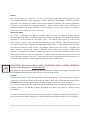
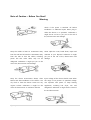
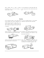
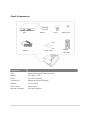
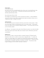
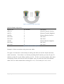
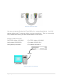
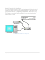
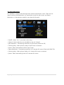
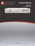
INSTRUCTION MANUAL
Stand-Alone 16Channel
DIGITAL VIDEO RECORDER
MODEL HDV043, HDV045
Ver. 010313
Copyright © 2011 Clover Electronics U.S.A. All Rights Reserved.
1 | Page
Preface
This manual contains user instructions on how to operate the Digital Video Recording devices (DVR
Unit), Remote Controller, Client Application, Mobile Application and Central Monitoring Software
Application. This manual also contains cautions and notifications regarding safe operating parameters
to protect the equipment and equipment operator.
Please read this manual and comply with its
suggested guidelines for proper operation of this equipment. For any other concerns or questions,
please inform your vendor for further information.
About This Guide
This guide is comprised of a Table of Contents where you will find Chapters divided logically
discussing particular topics. It is further divided by sections that discuss more detailed information
pertaining to certain features of the Chapter topics.
This manual also includes an Index section
where popular subjects or key concepts are referenced by page numbers. What this manual does
not cover are topics about upgrades and repairing the physical unit.
These should be done through
your vendors authorized repair center or by detailed direction from your vendor.
Upgrades and
repairs consists of adding and removing Hard Disk Drive, adding and removing a media drive,
upgrade or downgrade the Firmware, replace any electronic components inside the physical units.
These actions should be under the guidance of a qualified technician because improper actions may
cause permanent damage to the unit.
Some drives also have compatibility constraints and they are
constantly being updated as new products emerge from drive manufacturers.
IMPORTANT Information About HIGH DEFINITION SERIAL DIGITAL INTERFACE
Digital Video Recorders. PLEASE READ!!!!
High Definition Serial Digital Interface (HD-SDI) Digital Video Recorders are capable of providing Full
HD (1920x1080 Pixel Resolution) video through a new signaling method.
Cameras
HD-SDI cameras must be used with this DVR to provide Full HD video. Connecting a lower resolution
camera (ex. 600 TV Lines) to this HD-SDI DVR may result in poor and or distorted video/image quality.
Accessories (Video Baluns, Video Distribution Amp, Couplers, Connectors, Lenses, Cables etc…)
If you will be installing this unit, make sure that all accessories used are rated for HD-SDI DVR’s and
cameras. Failure to use HD-SDI qualified accessories and cables may result in unstable system
performance.
For more information about HD-SDI technology, please visit our website at http://www.cloverusa.com
You can also visit the HDCCTV Alliance ™ website at http://www.highdefcctv.org for more information.
2 | Page
Note of Caution – Before You Start!
Warning
Check if the power is switched off before
installation or additional repair. Never plug in
while the device is in operation. Otherwise it
might be set on fire or put you at the risk of
fire, electrocution and damage.
Keep the cables at least 15 centimeters away
Never uplift the cover, break down, repair and
from the wall and at least five centimeters away
maintain at your disposal. Otherwise it might
from the side so that the cables, including
put you at the risk of fire, electrocution and
power line and video cable, may not be
damage.
disfigured. Otherwise it might put you at the
.
risk of fire, electrocution and damage.
Keep the device environment always clean
Input voltage of the device should come within
before and after installation of the device. Use
the range of 10 percent of specified voltage.
dry cloth to clean the device. Never use any
Use separate wall power to keep heating
organic solvent. Otherwise it might be the
appliances,
cause of electrocution or mechanic disorder.
refrigerator. Otherwise it might be the cause of
including
fire and electrocution.
3 | Page
hair
dryer,
iron
and
When
strange
noise
or
smell
is
sensed,
Do not install device in humid place filled with
immediately plug out and send inquiry to
dust. It might be the cause of electrocution and
service center or seller.
fire.
Caution
Do not install the device in any place where
Do not put anything heavy on the product.
strong magnetic flow, electric wavelength and
Otherwise it may be the cause of disorder.
vibration may be sensed or where radio, TV or
other wireless device is located. Keep the
device away from magnetic flow, electric wave
or vibration.
Strong shockwave or vibration may be the
Be careful so that anything conductive may not
cause of mechanic disorder. Please be careful.
fall into the ventilation hole. Otherwise it may
be the cause of disorder.
Check if power switch and record on the front
When HDD is overloaded,you change the
side of the product is still turned on.
setting to keep recording. In that case, check if
it would be OK to eliminate the saved
4 | Page
data.
When HDD saving data gets old enough, video
data to be saved may suffer so much damage
When any abnormal sign is detected,
immediately contact seller or service center.
that it may be irreparable. If screen appears
broken while regenerating data saved in HDD,
it
means
HDD
won’t
work
any
longer.
Immediately contact service center to replace
them.
Caution : Any changes or modifications in construction of this device which are not expressly
Approved by the party responsible for compliance could void the user’s authority to operate the
equipment.
Note : This Equipment has been tested and found to comply with the limits for a Class A digital A
digital device, pursuant to part 15 of the FCC Rules. These limits are designed to provide reasonable
protection against harmful interference when the equipment is operated in a commercial environment.
This equipment generates, uses, and can radiate radio frequency energy and, if not installed and used
in accordance with the instruction manual, may cause harmful interference to radio communications.
Operation of this equipment in a residential area is likely to cause harmful interference in which case
the user will be required to correct the interference at his own expense.
Warning : This is a class A product. In a domestic environment this product may cause radio
Interference in which case the user may be required to take adequate measures.
5 | Page
Check Components
Battery
DVR
Adaptor
Screw
Power Cable
Components
DVR
Stand Alone Digital Video Recorder
Battery
1.5V (AAA) 2 pcs.
Screw
For HDD mounting
Software CD
Manual and Client program
Adapter
DC 12V 6.67A
Power Cable
Power cable
Remote Controller
For DVR operation
6 | Page
Software CD
Remote
Controller
Table of Contents
▒ Chapter 1. Features & Components ▒ .................................................................................. 10
1-1. Features ........................................................................................................................................................ 10
1-2. Name and Function of Front Panel ................................................................................................. 11
1-3. Rear Panel .................................................................................................................................................... 12
▒ Quick Setup ▒ ............................................................................................................................ 24
1. Placement ......................................................................................................................................................... 24
2. Connection....................................................................................................................................................... 24
3. Quick Power On ............................................................................................................................................ 26
4. Initial Boot ........................................................................................................................................................ 27
5. Setup Screen ................................................................................................................................................... 27
6. Labeling Camera ........................................................................................................................................... 28
7. Enable Recording .......................................................................................................................................... 29
8. Prepare Network ........................................................................................................................................... 30
▒ Chapter 2. Basic Information ▒ .............................................................................................. 32
2-1. Menu Display ............................................................................................................................................. 32
2-2. Description of Icon .................................................................................................................................. 33
2-3. Remote Controller.................................................................................................................................... 34
2-4. How to Set Remote Controller ID .................................................................................................... 35
2-5. How to Display Setup Menu ............................................................................................................... 36
2-6. Zoom In/Out............................................................................................................................................... 37
▒ Chapter 3. System Configuration ▒ ...................................................................................... 38
3-1. Information.................................................................................................................................................. 38
3-2. Time/Date .................................................................................................................................................... 39
3-3. Password ...................................................................................................................................................... 41
3-4. Hard Disk ..................................................................................................................................................... 42
3-5. Default Setup ............................................................................................................................................. 43
3-6. Upgrade ........................................................................................................................................................ 44
7 | Page
3-7. Button Setup .............................................................................................................................................. 45
3-8. RS-485 ........................................................................................................................................................... 45
▒ Chapter 4. Display ▒ ................................................................................................................. 46
4-1. OSD (On Screen Display) ...................................................................................................................... 46
4-2. Auto Sequence .......................................................................................................................................... 47
4-3. Spot Out ....................................................................................................................................................... 47
4-4. Video Output Setup ................................................................................................................................ 48
▒ Chapter 5. Network Setup ▒................................................................................................... 49
5-1. IP Address .................................................................................................................................................... 49
5-2. Notification.................................................................................................................................................. 50
5-3. E-mail Notification ................................................................................................................................... 51
5-4. Web Server .................................................................................................................................................. 52
5-5. Free DDNS ................................................................................................................................................... 53
5-6. Dual Codec Setup .................................................................................................................................... 54
▒ Chapter 6. Camera ▒ ................................................................................................................ 55
6-1. Camera Title ................................................................................................................................................ 55
6-2. PTZ Setting .................................................................................................................................................. 56
6-3. PTZ Advanced Setting ............................................................................................................................ 56
6-4. How to Use PTZ ........................................................................................................................................ 58
▒ Chapter 7. Record ▒ ................................................................................................................. 60
7-1. Record Setting ........................................................................................................................................... 60
7-2. Schedule Record ....................................................................................................................................... 61
7-3. Holiday Record .......................................................................................................................................... 62
▒ Chapter 8. Event Setup ▒ ........................................................................................................ 64
8-1. Sensor ............................................................................................................................................................ 64
8-2. Motion Detection ..................................................................................................................................... 65
8-3. Event Action ................................................................................................................................................ 67
▒ Chapter 9. Search ▒ .................................................................................................................. 69
9-1. Search Menu .............................................................................................................................................. 69
8 | Page
9-2. Calendar Search ........................................................................................................................................ 70
9-3. Date/Time Search ..................................................................................................................................... 71
9-4. Event Search ............................................................................................................................................... 72
9-5. Go to First / Go to Last ......................................................................................................................... 73
9-6. Search Control ........................................................................................................................................... 73
9-7. Audio ............................................................................................................................................................. 74
▒ Chapter 10. Backup ▒ ............................................................................................................... 75
10-1. Backup ........................................................................................................................................................ 75
▒ SPECIFICATIONS ▒ .................................................................................................................... 79
▒ Chapter 11. Mobile Applications Web Viewer DDNS ▒……………………………..………………………………...80
▒ INDEX ▒……………………………………………………………………………………………………………………………………………114
9 | Page
▒ Chapter 1. Features & Components ▒
1-1. Features
The highly advanced and high-performance video recorder is designed to make it easier to
install and use with safety.
Main Feature
ㆍ Able to control the PTZ by using mouse like joystick
ㆍ Front USB port for easy backup
ㆍ Able to back up by ODD (optional)
ㆍ Support GIGA bit Ethernet.
ㆍ Able to access internet with dynamic IP address
ㆍ Support Dual-Stream network transmission.
ㆍ Able to output simultaneously thru TV, VGA, S-VHS, Spot
ㆍ Able to set the resolution, frame and quality per channel.
ㆍ Support a number of PTZ protocol
ㆍ Support Central Monitoring Software (CMS).
Application Range
√ Banks, ATM machine, supermarket, convenience store and other places
√ Residential area, apartment buildings, jewelry store, commercial building
√ Places requiring safety for children such as school, elementary school and playground
√ Warehouse, storage house and workplace
√ Places requiring remote surveillance
10 | P a g e
1-2. Name and Function of Front Panel
(HDV043)
[1] POWER LED [2] RECORD LED [3] USB Port
[5] QUAD Button
[4] MENU Button
[6] REC Button (Emergency / Schedule)
(HDV045)
No
1
Button/Function
Direction Button /
Playback Button
Description
Use as a control button on Setup menu
Speed control on playback, Stop button, Pause button.
2
Menu
Display a menu, Move to upper menu, Cancel a function
3
Pan/Tilt
4
Audio
Display Audio listening menu
5
Backup
Display Backup function of video data
6
Number
Channel selection or number input
7
LED Status
Display Pan/Tilt menu
Show status of Power, Recording, Remote Access, Schedule
Recording and Emergency Recording
11 | P a g e
8
Function Button
9
Front USB Port
10
ODD
Search
Display search menu
Split Mode
Select split mode
Sequence
Automatic screen shift
Schedule Recording
Schedule recording
Emergency Recording
Emergency Recording
USB Connecting slot
Available to connect ODD
1-3. Rear Panel
No
Button/Function
Description
1
Power
Power Input
2
External SATA Port
External storage and backup port
3
VGA
VGA Monitor Output
4
Audio Out
Audio Output
5
HDMI Out
HDMI Video output
6
Audio Input
Audio Input
7
Video output
CCTV Monitor Output
8
SPOT
SPOT Output
9
Video Input
Camera Video Input
10
Serial Port
RS-232 Port
11
Tx, Rx, Sensor, Alarm
Pan/Tilt(Tx, Rx), Keyboard(Tx, Rx), Sensor Input,
Alarm Output
12
LAN Port
RJ-45 Ethernet Port
13
Rear USB port
USB Connection Slot
12 | P a g e
Rear Port Specification and Connection Examples
Power input
Input at 12 volt DC with positive polarity at 5 Amp
VGA (Video Graphics Array) Port
VGA port uses D-subminiature or D-sub, DE-15F (E rated sized D-Sub with 15 pin Female)
port.
Connect a VGA monitor to the DVR with a standard VGA Cable.
17” LCD or CRT monitor or above.
Figure 1 VGA Connection Configuration
13 | P a g e
We recommend using a
Figure 2. VGA Pin Configuration
VGA Pin Configuration Table
Signal Type
Pin Number
Description
RED
1
Red video (75 ohm, 0.7 V pp)
GREEN
2
Green video (75 ohm, 0.7 V
p-p)
BLUE
3
Blue video (75 ohm, 0.7 V pp)
RES
4
Reserved
GND
5
Ground
RGND
6
Red ground (Red return)
GGND
7
Green ground (Green return)
BGND
8
Blue ground (Blue return)
KEY / PWR
9
Key (not used) / +5V DC
SGND
10
Sync ground
ID0
11
Monitor ID bit 0
SDA
12
Bidirectional data line
HSYNC or CSYNC
13
Horizontal or Composite
Sync
VSYNC
14
Vertical Sync and data clock
SCL
15
Data clock
Table 3 VGA Pin Configuration
14 | P a g e
Main Monitor Output
Connect a monitor that supports BNC Inputs or use a “BNC Twist Lock” to Composite Video
adapter if your monitor only supports Composite Video Inputs.
Figure 4 Main Monitor Connection
The display resolution for Monitor is at 720x480.
[Please refer to the 오류! 참조 원본을 찾을 수 없습니다., 오류! 참조 원본을 찾을 수
없습니다., 오류! 참조 원본을 찾을 수 없습니다. item marked “⑦” Main Monitor Output].
SPOT Monitor Output
Connect a monitor that supports BNC Inputs or use a “BNC Twist Lock” to Composite Video.
The display resolution for Monitor is at 720x480.
15 | P a g e
Camera Input
The camera connections are the input ports for the video signal(s) used with the DVR.
You
may use any video source (75ohm) that outputs via a BNC connector (Twist Lock Type).
If
your video source outputs via RCA/Composite video, the proper adapter must be used
when connecting the cable to the camera connection input port(s) of the DVR. Both NTSC
and PAL signals are automatically detected by the DVR and requires no further
configuration.
Figure 5 Camera Connection
Connect the cameras to the Video In ports located on the rear panel of the DVR using the
proper cables and connectors (BNC Twist Lock).
The corresponding video channels can be
“looped” out using the “loop out” ports located beneath each video input port.
need for terminators to be installed, each port is self terminated.
There is no
Both NTSC and PAL
signals are automatically detected by the DVR and requires no further configuration.
16 | P a g e
RS-232 Serial Connector
The RS-232 COM port is used to connect the DVR to a PC (optional updating procedure) or
to connect an external device like a DVR controller (optional).
The required settings to use
the RS-232 port can be configured in the DVR settings.
Pin 1
Pin 9
Figure 6 DE-9M Serial Port
RS-232 / DE-9M Serial Port Pin Configuration Table
Signal Type
Pin Number
Description
DCD In
1
Carrier Detection Signal (not
used)
Rx
2
RS232 Receive
Tx
3
RS232 Transmit
N/C
4
No Connection
GND
5
System Ground
N/C
6
No Connection
RTS
7
RS232 Request To Send
Signal
CTS
8
RS232 Clear To Send Signal
N/C
9
No Connection
Table 7. RS-232 Pin Configuration
17 | P a g e
Optional Alarm Sensor Extension Box
There is an optional Alarm Sensor Extension Box that connects to RS-232 port provided in
our DVR unit..
① Power switch
② Power adaptor connector
③ RS-232 port (Port connected to the system)
④ Sensor input (1~16)
⑤ Normal Open alarm output : 1~16
⑥ Normal Close alarm output : 1~16
Figure 8 Connection Example of Extension Box
Sensor 1~16 inputs functions same as the S1~S4 inputs (see next section in 10-way terminal
Block).
Difference is that every port is issued with its own ground connection located right
below. Additionally there are 16 NO (Normally Open) dry contact points with dedicated
ground and 16 NC (Normally Closed) dry contact point with dedicated ground per points.
These NO, NC points are used in Access control integration.
18 | P a g e
RS-485 Connections
The RS-485 ports are used to connect external PTZ cameras to the DVR.
available port with this DVR.
There is single
External controllers may be used, however you will not have
the ability to control the PTZ cameras remotely if you do so.
There are single RS-485 communications ports, these ports are used to connect external PTZ
camera controllers.
Figure 9 PTZ and Keyboard in RS-485
Alarm Out
Connecting the alarm out:
Each alarm output can be controlled/switched by DVR unit and its application software.
Each device must be wired to C (Common) and NO (Normally Open) and 12V DC ground
voltage must be applied to the port.
Figure 10 Alarm Out
19 | P a g e
Sensor Input
Connecting the Inputs:
Each alarm input can be controlled/switched by a device such as a motion/IR sensor, door
contact sensor, and similar devices.
Each device can either be wired as N/O or N/C
(Normally Open/Normally Closed).
Dry contact sensor direct to DVR:
This example is the simplest form of sensor connection for DVR unit.
Sensors dedicated
only for the function for the DVR and example below depicts that Motion Sensors are not
outputting any type of voltage (dry contact).
USB Connection
The USB connection ports are used for both back up and mouse control purposes.
port can be used for back up via USB memory stick or for mouse control.
for the two USB ports are for firmware updating procedures.
Either
A third option
You will only need to use one
port for firmware updates.
Two USB ports
are located one front side of the DVR and the other in rear side of the DVR.
These ports may be used for both USB mouse connection and for USB memory stick back
up procedures
Ethernet Port
The RJ-45 port is used to connect the DVR to a network through a DTE (Data Terminal
Equipment) device such as a switch or router with an integrated switch.
To connect the
system to a network please use a standard RJ-45 cable (patch/straight through) and make
sure both ends of the cable are securely connected to the proper ports.
IT administrator for detailed configuration procedures and setup.
length for Category 5e, RJ-45 cable is 100 meter or 300 feet.
20 | P a g e
Consult your local
The maximum cable
Figure 11 Ethernet Cable Color Code
EIA/TIA E568B Configuration
Signal Type
Pin Number
Description
LAN Tx+
1
Ethernet Transmit Positive
LAN Tx-
2
Ethernet Transmit Negative
LAN Rx+
3
Ethernet Receive Positive
Not Used
4
Not Used
Not Used
5
Not Used
LAN Rx-
6
Ethernet Receive Negative
Not Used
7
Not Used
Not Used
8
Not Used
Figure 12 Ethernet Pin Configuration
Example 1. Direct connection using cross over cable
This type of connection is used mostly for testing the DVR unit and for simple and short
cable connection.
Since there is no devices providing DHCP services you must fix your IP
address to static IP to your DVR as well as your PC.
If this is not done properly, then there
connectivity of the unit to the PC will not happen. First you must use cross over network
cable. This is a cable created with crossing pin 1 to 3, 2 to 6 then pin 3 to 1, 6 to 2.
21 | P a g e
Figure 13 Cross Over Cable
You may now connect directly into PC and DVR unit to communicate directly. Your DVR
gateway address and PC’s gateway address must be same address.
Then you must assign
TCP/IP address that belongs to same subnet address as DVR and PC.
Example IP address for DVR
DVR TCP/IP address: 192.168.0.2
PC’s TCP/IP address 192.168.0.3
DVR’s subnet: 255.255.255.0
PC’s subnet: 255.255.255.0
DVR’s gateway: 192.168.0.1
PC’s gateway: 192.168.0.1
CAT 5 E
Figure 14. Direct PC Connection
22 | P a g e
Example 2. Connecting DVR unit to Router
This is most common connection for DVR it is advised that your DVR follow the rules of
network policy (Please consult with your network administrator). In this example we are
going to assume that router is giving (leasing) TCP/IP address.
When router is giving
TCP/IP address to the unit this action is possible via Dynamic Host Control Protocol
otherwise known as DHCP.
Figure 15 Modem and Router Configuration
23 | P a g e
▒ Quick Setup ▒
1. Placement
Step 1. Preparation
Remove unit from out of the box and place it on the table top as seen below.
Figure 16 Table top placement
2. Connection
After unpacking the unit you must connect all camera connections, monitor connections,
network connection, power connection and other optional connections.
Step 1. Connect Cameras to DVR unit
Figure 17 Camera to DVR
24 | P a g e
Step 2. Connect monitor to DVR unit
Depending on what type of monitor you are connection connect either to VGA or BNC
monitor of your choice.
If you have both types of monitor you may connect both of them.
Figure 18 VGA or Monitor Connection
Step 3. Connect Network Cable to DVR unit
Figure 19 Ethernet Cable to DVR Unit
Step 3. Optional PTZ, Sensor, Alarm
Figure 20 Terminal Block Connection
25 | P a g e
3. Quick Power On
Power input – connection port for DC 12 volt
Step 1. Included DC Power adapter is located in accessory box.
Step 2. Take the adapter and connect it with power cord.
Step 3. Connect the DC 12V male connector to female DC 12V port.
Step 4. Connect to the wall outlet then plug the cable into the DVR.
26 | P a g e
4. Initial Boot
After turning on the DVR unit it will go into a boot sequence.
At the initial boot section
there is no user interaction with DVR unit however please observe to see if DVR unit is
properly booting.
As you may notice progress bar will indicate booting progression, if there is no activity for
long period of time then possible corrupt or damaged firmware in DVR unit. Please indicate
such failure and contact technical support.
5. Setup Screen
To initiate setup menu you may use following method
Mouse
Remote
Frontal Keypad
Right mouse click anywhere on the
Press button labeled “Menu” on
Pressing button labeled “Menu” on
screen of DVR
remote controller
front of DVR unit’s directional key
pad button.
27 | P a g e
6. Labeling Camera
Sometime camera location may be identified easier by giving logical name to the camera.
Here are steps to give logical name label instead of having default label.
Here you may choose camera(s) that you want to give logical name and repeat to other
camera(s) as needed. In this example we have chosen Camera 1 marked Ch1 and will
change the label to door1.
Click Camera Number to change then use the on screen key pad to change the label as
shown below. When done giving name select and choose Enter to end typing.
28 | P a g e
7. Enable Recording
Main and primary function of DVR is to record video.
configure all cameras to record immediately.
Below section is showing how to
DVR already may be configured to record on
the HDD.
Step 1. Select “Record” item on upper main category then by default “EVENT RECORDING”
tab should appear as shown on screen below.
Figure 21 Event Recording Page
Step 2. You may also select "All" from the Channel (#) to modify all the channels at one
time.
29 | P a g e
8. Prepare Network
Step 1. Select “Network” item on upper main category then by default “IP ADDRESS” tab
should appear as shown on screen below.
Figure 22 IP Address Page
Make sure that DHCP is selected if you have a router that leases IP address to network. If
you want to give the IP Address value to unit directly then uncheck the DHCP check box
and input IP Address directly where
(Arrow) is pointing to. Also make sure to
assign proper port number as shown above.
Important Note: when to use DHCP vs. Static IP
DHCP is short for Dynamic Host Communication Protocol where IP address is given to the
DVR and these IP address are leased to the unit. Usually IP address are none routable
internal IP Address.
Internal IP address or known as Private IPv4 address, they may be
starting with 192.168.0.0 ~ 192.168.254.254 (16-bit block enabling 65,536 IP address set)
also known as class C IP address, 172.16.0.0 ~ 172.31.254.254 (20-bit block enabling
1,048,576 IP address set) also known as class B address, or 10.0.0.0 ~ 10.254.254.254 (24-bit
block enabling 16,777,216 IP address set) also known as class A address. So if your router
or DHCP server gives the IP address that are class A, B, or C address shown then you can
confirm that there is a DHCP services available on your network but if you get IP address
30 | P a g e
ranging from 169.254.1.0 ~ 169.254.254.255 then you have been assigned pseudorandom IP
address and it is a indication that there are no DHCP service available for DVR device.
Static IP setting is used when your ISP (Internet Service Provider) gives routable IP they are
call Public IPv4 address. They are IP address that points to the DVR unit without relying on
DHCP service. In situation such as this case you may configure IP address as recommended
by ISP. Often times Static IP is still used with class A, B, or C address. In those cases, you
must point to IP addresses that are not in lease range of the DHCP scope (IP address not
issued by DHCP services but must be in same Subnet and Gateway IP).
Users tend to use
this method when certain IP address out of DHCP scope where particular IPs are configured
to use NAT, IP forwarding, or DMZ (NAT, IP forwarding and DMZ are used in most router to
enable incoming traffic to specific IP addresses).
Step 2. Configure Port for incoming traffic. You must have NAT, IP forwarding or DMZ
configured in your router in order to allow in bound traffic to your network. And Port assign
to allow inbound traffic to local IP assign to DVR should be identical to Port configuration
with DVR. See figure below but your router configuration page might look different.
and DVR.
Figure 23 Port Forwarding Example
All above steps mentioned in Chapter 3. Quick Setup will ensure that you will have DVR
connect to Cameras, enabled recording and basic network configuration.
31 | P a g e
▒ Chapter 2. Basic Information ▒
2-1. Menu Display
It’s available to make setup with menu button on front panel, a mouse and a remote
☞
Display Setup Menu with a front panel button
There are ‘Menu’ button on the front of unit. Press it to display Menu.
☞
Display Setup Menu with a remote
Press Menu button on a remote.
☞
Display Setup Menu with a mouse
Mouse right click to display pop-up menu. Select the menu you want to do setup.
32 | P a g e
2-2. Description of Icon
[1] The icons on the live screen indicate the status.
Recording
Video Loss
Motion Detection
Sensor
[3] Status Bar
1. Display date and time
2. ER means Emergency Recording and SR means Schedule Recording.
3. Show network status and key lock
4. Show HDD status and display “Overwrite” when overwriting previous data.
33 | P a g e
2-3. Remote Controller
It is available to control every function with a remote. Controlling several DVRs with a remote is
available..
[1] ID : Press to select a remote controller ID in case of using one remote
controller to
multi DVRs.
[2] SPLIT : Press to see split mode. Once press. Same button with Quad button
[3] BACK UP : Press to start recorded data archiving to external media
[4] AUDIO : Select a audio channel
[5] SEQ : Press to display each camera in sequence for specific duration.
[6] PTZ : PTZ control menu...
[7] SEARCH : Call search menu to playback recording image.
[8] NUMBER BUTTON : Input the channel number to make full screen mode or the number
in setup menu.
[9] SET UP : Press to display setup menu.
[10] DIRECTION KEY / CONFIRM BUTTON / PLAYBACK CONTROL
[11] Record Button
• EMERGENCY : Emergency Recording Button
• SCHEDULE : Schedule Recording Button
34 | P a g e
2-4. How to Set Remote Controller ID
In order to use remote controller, the ID must be same both DVR and remote controller. By
assigning DVR ID, it allows the user to control multiple DVRs with one remote controller.
[1] Check current system ID and can be changed by user. (Factory default ID: “0”)
Menu > System > Information > Remote ID (Range: 0 ~ 99 )
System ID must be configured on DVR system menu. It cannot change DVR system on
remote controller.
[2] How to use remote controller
ID must be identified between remote controller and system. Otherwise remote controller
doesn’t recognize DVR correctly.
Remote controller ID menu displays as above image when you press ID button of remote
controller.
• DVR ID : It displays current ID of the system.
• “0” : Input the same ID number of DVR and press “Confirm”
35 | P a g e
2-5. How to Display Setup Menu
It is available to display menu with front panel buttons, remote and mouse.
[1] Front panel button : Push “MENU” button on the front panel.
[2] Mouse : Right-click
[3] Remote : Push “MENU“ button
Go to main menu
Go to search menu
Go to backup menu
Go to audio output menu
Start emergency recording
Start schedule recording
Go to PTZ Control menu
Start sequence
Switch output to Alarm or internal buzzer
Change display split mode
Magnify the image at live or playback
36 | P a g e
2-6. Zoom In/Out
Magnify the image at live or playback.
[1] How to magnify with a mouse
Locate the mouse pointer on the place you want to magnify. And click the left button of
mouse and drag it. You can cancel by dragging with mouse left button clicked. (Also you
may use “Zoom In / Zoom Out” menu by displaying menu)
[2] How to magnify with a remote (Front panel button)
• On Live : Display Menu and select “Zoom In/ Zoom Out”. And move with direction
buttons.
Select Menu button to cancel
• On playback : Select “Emergency Recording” and move with direction buttons.
Select Menu” to cancel.
37 | P a g e
▒ Chapter 3. System Configuration ▒
3-1. Information
[1] Remote ID : Assign the ID of remote controller, so that user can separately control
multiple
DVR unit with one controller. (ID range: 0 ~ 99)
[2] Mouse Resolution : Mouse sensitivity level can be adjusted at user’s convenience.
(Basic Level 1; Slow speed, Level 1 < Level 2 < Level 3 to increase reaction speed.)
[3] Language : Select a language
[4] Vertion : Show S/W, H/W and N/W
[5] Health
: Indicates storage status
• Hard Disk 1~3 : Display the temperature of hard disk
• E-SATA : Display the temperature of hard disk connected to E-SATA
• Board : Display the temperature of the DVR’s main board.
[6] Video Detect Mode : Select a video signal format. (NTSC / PAL)
[7] Video Mode : Display video signal format
[8] WEB Code : DDNS ID for DDNS connection.
[9] MAC Address
38 | P a g e
3-2. Time/Date
[1] Time : Set time
[2] Date : Set date
[3] Date format : Select a Time/Date display format.
[4] Daylight Saving Time : Set “ON” to apply daylight saving time.
Enter Month/Week/Day to begin and also enter Month/Week/Day to end.
[5] Time Server : Set time automatically through internet.
39 | P a g e
• Time server
: Input the URL of server (Default : kr.pool.ntp.org )
• Synchronize Period : Select the period to syncronize between DVR and time server
• Power On : Try to sync once power on.
• 12Hour : Try to sync every 12 hours.
• 24Hour : Try to sync every 24 hours.
• Time Zone : Select Standard time
[6] Apply : Save and apply time / date setting.
40 | P a g e
3-3. Password
[1] ID : Available to register max 8 account(“Admin” and “User1~7)
• admin : Administrator ID
• User1~7 : User ID
[Note] Default password of all ID is “11111111”.
[2] Assign an authority per selected ID
• Configuration : Available to set configuration
• Hard Disk : Available to set Hard Disk
• Search : Available to search
• Backup : Available to back up
• PTZ Setting : PTZ operation is available
• PTZ OSD Menu : Assign an authority to display PTZ OSD menu
• Record Key : Assign an authority to use “REC” on the front
• Camera : Available to see the selected channel
41 | P a g e
3-4. Hard Disk
As it is related to recording, if any setting is wrong, system error or abnormal recording
could happen.
[1] Hard Disk List : It provides the information for Hard Disk, external USB Hard Disk and
format.
• Hard Disk 1~3 : Display the Hard disk capacity internally mounted
• E-SATA : Display the capacity of E-SATA
• Delete : Select a disk and format(delete) it
[2] Total : Display total capacity and used capacity of Hard Disk
[3] Over write : Record continuously by overwriting the hard disk
[4] Erase Data : Format several hard disks altogether.
• Main Disk : Format all the mounted disks named “Main disk”
• Mirror Disk : Format all the mounted disks named “Mirror Disk’
[5] Auto Delete : Keep the recorded data for the selected period and automatically delete the
previous data.
42 | P a g e
[6] Advanced : Select whether a Hard Disk is used as Main disk or Mirror disk.
• Hard Disk 1~3 : Select with which purpose it will be used.
• E-SATA : Select with which purpose it will be used.
• Apply : Save the setting
[Note] After setting, select “Apply” to save. Then, the system is rebooted.
3-5. Default Setup
[1] Default Setup : Except major configuration (Network, Password), parameters are
initialized.
[2] Factory Setup : All parameters are initialized.
43 | P a g e
3-6. Upgrade
[1] USB (Firmware Upgrade) : In order to upgrade system firmware with USB memory stick,
the firmware file must be saved in the USB storage first and then insert to DVR to start USB
upgrade from the menu.
[2] Configuration Backup : Save a configuration file of DVR.
[3] Configuration Load : Upload a configuration file to DVR.
44 | P a g e
3-7. Button Setup
After a certain time passes, screen is automatically locked.
• Auto key lock : There is no key input during specific time, system locks the button
automatically. In order to unlock, input the password. ( 10 sec. 30 sec. 1 min. OFF)
• Key Beep : If you select ON, beep sound occurs
3-8. RS-485
In order to control the PTZ camera or control keyboard, DVR supports RS-485 port.
Baudrate /Parity /Stopbit : Refer to the manual of “Keyboard” or “PTZ camera”
45 | P a g e
▒ Chapter 4. Display ▒
4-1. OSD (On Screen Display)
[1] Camera Title : ON / OFF
[2] Status Bar : ON / OFF.
[3] Login Display : Select a login option
• As Per Last Login : Display live image after system rebooting.
• Cover All Camera : Do not display live image after system rebooting.
[4] Login menu :
Select a log in option.
• Always from boot : Input the password after rebooting.
• Boot after lock : Auto login after rebooting.
46 | P a g e
4-2. Auto Sequence
• Auto Loss Skip : If there is no video input, it skip video loss channel.
• Display time : Select a display duration while sequencing (1 sec. ~30 sec.)
[Note] Sequence doesn’t work on event pop-up.
4-3. Spot Out
Control extra spot output on rear panel. By using additional monitor, event triggered video
display and sequence display are available.
[1] Mode
• Sequence : Display videos in selected time order per channel.
• Event : Display event triggered channel.
• Seq+Event : If an event is triggered, the video is displayed first and then in sequence.
[2] Display Time : Set time per channel applied in sequence display.
47 | P a g e
4-4. Video Output Setup
You can choose a type of video output. This model supports HMDI, VGA and composite
output.
[1] Video Output Setup
• HDMI+VGA(S) : Set HDMI as main output and VGA as Spot Out.
• VGA+Composite(S) : Set VGA as main output and Composite as Spot Out..
• HDMI+Composite(S) : Set HDMI as main output and Composite as Spot Out..
[2] Vga Resolution : Select a resolution for VGA out.
(Resolution : 1920*1080 , 1440*900 , 1366*768 , 1280*1024, 1280*720 , 1024*768 )
NOTE : HDMI out is fixed at 1920 x 1080 and it is not able to video out with VGA out
simultaniously.
48 | P a g e
▒ Chapter 5. Network Setup ▒
5-1. IP Address
It is the system setup for remote monitoring or backup and it needs the network setup of
DVR.
The user must know whether their internet is dynamic IP(DHCP) or fixed IP. Please check it
to your ISP before setup.
[1] DHCP : “ON” for dynamic IP user.
“OFF” for static IP user.
[2] IP Address : Input the IP address.
[Example]
• IP address : 61.250.152.050
• Subnet Mask : 255.255.255.000
• Gateway : 61.250.152.001
• DNS Address : 164.124.101.002
[3] DDNS Address : Do not change the DDNS server IP (61.250.157.15)
[4] Use Port : Default port is 3000.
[5] Upnp : If a router supports Upnp, it automatically set port forwarding.
[NOTE] In case of using the router, the user should make port forwarding.
The port forwarding function is described on the router manual.
49 | P a g e
5-2. Notification
E-Mail Setup
It’s a basic setup to send E-mail, so if it is not correct, e-mail couldn’t be delivered. So be
careful to make Setup correctly.
[1] SMTP Server : Enter Mail Server address to use as SMTP Server. If you don’t know the
Server address, contact a person who manages SMTP Server you use.
[2] Mail From : Enter the mail address which you use. (It is for preventing a mail blocked as
spam.)
[3] Mail Address : Enter recipient’s mail address (Available up to 3 account)
[4] Password : Select if ID/Password input is necessary when sending a mail.
[5] Use Port : Most of Mail Servers use 25 for port. Check Port if system doesn’t work after
setting.
50 | P a g e
5-3. E-mail Notification
Select which type of notifications you are going to use.
Notification type : You can select the type for E-mail notification.
• Alarm : E-mail is sent with still image when an alarm occurs
• Sensor : E-mail is sent with still image when triggering a sensor
• Motion Detection : E-mail is sent with still image when detecting a motion.
• Video Loss : E-mail is sent when video input is lost.
• Power On : E-mail is sent when power is on after off.
• Password Modify : E-mail is sent when the system password is modified
• HDD Error : E-mail is sent when HDD error happens
51 | P a g e
5-4. Web Server
Built-in web server make user can connect the DVR remotely on the Internet Explorer
[1] ON/OFF : Select ‘ON’ to use remote N/W connection through web.
[2] USE PORT : Port for remote connection
52 | P a g e
5-5. Free DDNS
Free DDNS is used for remote connection through private DDNS service.
Firstly, go to http://www.dyndns.com and create an account. Then, if your system is installed
with a router, you must make DMZ setting in the router setup for the IP your system has.
DMZ is a function to open all the ports for the selected IP.
Input registered information in DVR setup.
• DDNS address : Select the private DNS service name (Select DynDns )
• User name/ Password/ DVR Address : After creating an account in the relevant website,
input the ID/ Password/ URL information allocated to DVR setup.
53 | P a g e
5-6. Dual Codec Setup
It is available to transmit data through extra network transmission codec. There are two
ways of setting. Split Resolution is a transmission mode for split screen and Popup
Resolution is a transmission mode for one channel full screen.'
• On/Off : Select “On” to use dual codec setup
• Channel : Select channel to set (Available to set per channel)
• Split Resolution : Transmitting resolution of split screen (Fixed with CIF)
• Picture Quality : Select picture quality of split screen to transmit
• Speed : Select transmission frame of split screen
• Popup Resolution : Transmitting resolution of 1 channel full screen (Fixed with 1280*720)
• Picture Quality : Select picture quality of 1 channel full screen to transmit
• Speed : Select transmitting frame of 1 channel full screen 54 | P a g e
▒ Chapter 6. Camera ▒
6-1. Camera Title
Input a camera title using by virtual keyboard.
Press a space bar to change a language.
55 | P a g e
6-2. PTZ Setting
[1] Channel: Select a channel
[2] ON/OFF : Enable or disable to use PTZ.
[3] MODEL : Select the PTZ protocol or, model
[4] ID : Select the PTZ ID.
(For more detail, refer to the manual of PTZ device.)
6-3. PTZ Advanced Setting
[1] Reverse Control (Pan) : Set the Pan works reverse direction.
[2] Reverse Control (Tilt) : Set the Tilt works reverse direction.
[3] Touring Mode
• Preset Touring : Use touring by DVR setting.
• Camera Touring : Use touring by camera setting. (PTZ camera built-in touring function is
available only.)
[4] Setup Preset Touring
It is operable when you select the ‘preset touring’ from the touring mode’ menu.
56 | P a g e
The touring number is selectable 1~16.
[1] Touring number : Select the number.
[2] Preset number : Select the preset number saved before.
[3] Touring interval (/SEC) : Select the touring dwell time.
[NOTE] PTZ protocol selection
Protocol is PTZ moving driver. The protocol is registered as per the camera model
name or protocol name. Please check whether you PTZ is usable for this DVR. The
touring is supporting when the camera itself support the touring function.
57 | P a g e
6-4. How to Use PTZ
[How to call the PTZ menu]
• Mouse menu: Click the right button of mouse and select the ‘PTZ’.
• Remote controller menu: Click the “PTZ” from remote controller.
(1) Select PTZ Button on the remote controller
• When you select PTZ button, + shape icon appear. Then move to the channel you want by
the direction key.
(2) If you moved to PTZ channel, then after pushing “SET UP” button, select the menu to
operate.
58 | P a g e
• PanTilt : Control the direction by the direction key in remote controller.
• Preset : Input the preset number to be moved or saved and select this menu.
(Preset Save)
(Preset moving)
• Tour : It tours as per the saved preset number.
• MENU : It can recalls the PTZ camera OSD menu
• Channel : Change channel at split screen. Available to move with direction button after
selecting a channel. (Only work on split screen)
• Auto Focus : Adjust the focus automatically.
• Exit : Escaping the PTZ mode
59 | P a g e
▒ Chapter 7. Record ▒
7-1. Record Setting
Set resolution, quality, recording speed and audio. Each setting affects the size and picture
quality.
[1] Channel : Set channel
[2] On/Off : Set On or Off for recording
[3] Resolution : Set resolutioin
[4] Quality : Set picture quality of recorded video
[5] Speed : Set record frame
[6] Post-Recording : Set recording duration time after an event is triggered.
[7] Record Audio : Set On or Off for audio recording
60 | P a g e
7-2. Schedule Record
Set schedule record per day of the week, time and channel. And setting per hour is also
available.
█ N (Grey) : No record
█ C (Green) : Continuous record
█ M (Blue) : Motion detected record
█ S (Red) : Sensor triggered record
█ M+S (Yellow) : Recording by motion detection or sensor triggering
[How to setup]
• Select a channel
• After selecting the day of the week and time, every mouse click makes color shift like
N(Grey) → C(Green) → M(Blue) → S(Red) → M+S(Yellow)
• After selecting the other day of the week and time, every OK button click makes color
shift.
• Clear : Delect the schedule of the selected channel
• Channel Copy : Copy the currently set recording schedule to the selected channel.
61 | P a g e
• All Ch to Copy : Copy the currently set recording schedule to all channels.
7-3. Holiday Record
Set holiday record with different option.
[1] 7 different holiday setup can be made.
After selecting record type from H1 to H7, set time with dragging mouse or remote
direction.
[2] Select the Holiday on Holiday Calendar and then set the holiday type among H1 to H7.
Every mouse click on the selected date makes color shift and available to set from H1 to H7.
62 | P a g e
63 | P a g e
▒ Chapter 8. Event Setup ▒
8-1. Sensor
It is for sensor setup.
[1] Sensor Input : Select the sensor input channel.
[2] On/Off : Select the sensor usage.
[3] Input Type: Select the sensor input type.
• N/Open (NORMAL OPEN) : The contact is normally opened but close when the signal is
generated.
• N/Close (NORMAL CLOSE) : The contact is normally closed but open when the signal is
generated.
[4] Related camera: Select the camera to be related with sensor. Multi-selection is possible.
64 | P a g e
8-2. Motion Detection
It is the motion detection setup menu.
[1] Channel : Select the motion detection channel.
[2] On/Off : Select the motion detection usage.
[3] Sensitivity : Select the sensitivity of motion detection. Please apply it after the actual
testing.
[4] Detection Area: Select the motion detection area. ( 1~5 )
The cursor moving by the direction key and if press “enter”, this block is designated for
motion detection.
• MD selected area : Pink color
• MD non-selected area : Transparent
• If the movement is detected, the color of that area turns green.
[Using mouse]
Locate the pointer on start point and click the right button then dragging to the ending
point.
65 | P a g e
66 | P a g e
8-3. Event Action
Event record will be made as per the setup.
[1] Motion : It is the setup for PTZ, pop-up, relay out, buzzer in motion detection.
• Channel : Select the channel to apply.
• Preset channel : Select the preset camera being applied for the event.
• Preset number : Select the preset number to move.
• Popup Channel : Select the usage Popup usage by ON/OFF.
• Popup Duration : Popup window floating time.
• Relay out : Select the alarm out
• Relay duration : Relay out duration.
• Internal buzzer : Internal buzzer usage.
67 | P a g e
[2] Sensor : It is the setup for PTZ, pop-up, relay out, buzzer in sensor triggering.
• Preset channel : Select the preset camera being applied for the event.
• Preset number : Select the preset number to move.
• Popup Channel : Select the usage Popup usage by ON/OFF.
• Popup Duration : Popup window floating time.
• Relay out : Select the alarm out
• Relay duration : Relay out duration.
• Internal buzzer : Internal buzzer usage.
[3] Video loss : It is the setup for PTZ, pop-up, relay out, buzzer in video loss.
• Preset channel : Select the preset camera being applied for the event.
• Preset number : Select the preset number to move.
• Popup Channel : Select the usage Popup usage by ON/OFF.
• Popup Duration : Popup window floating time.
• Relay out : Select the alarm out
• Relay duration : Relay out duration.
• Internal buzzer : Internal buzzer usage.
68 | P a g e
▒ Chapter 9. Search ▒
9-1. Search Menu
It supports the various ways of search mode such as Calendar, Date/Time, Event, etc.
[1] How to call menu : Select the “SEARCH” from remote controller and right button of
mouse.
[2] Search mode selection
· Calendar search: It searches by calendar.
· Date /Time search: It searches specific Date/Time.
· Event search: It searches as per the event.
· Go to first : It searches the first recorded data on HDD.
· Go to last : It searches the last recorded data on HDD.
69 | P a g e
9-2. Calendar Search
It searches using by the calendar.
[1] If there is the recorded data on DVR, it shows red color on recorded date. Using the
direction
key, you can change the YEAR/MONTH/DATE.
[2] If there is the recorded data, it shows red color so, press the enter button on selected
date.
(Channel display could be different per model 4ch/8ch/16ch)
[3] The recorded data shows as a graph and select the minutes to search.
70 | P a g e
(Channel display could be different per model 4ch/8ch/16ch)
9-3. Date/Time Search
If you know the specific date/ Time, input the time to search.
[1] Record begin : It shows the record began time.
[2] Record end : It shows the record end time.
[3] Channel : Select the channel to search.
[4] Play Begin : Input the time to search.
[5] Play : If you click “Play”, it playback the selected time.
71 | P a g e
9-4. Event Search
It searches event recorded data.
[1] Record begin : It shows the record began time.
[2] Record end : It shows the record end time.
[3] Channel : Select the channel to search.
[4] Play Begin : Input the time to search.
[5] Play : If you click “Play”, it playback the selected time.
72 | P a g e
9-5. Go to First / Go to Last
It searches the first or last recorded image.
9-6. Search Control
[Control by Mouse]
Description of search button
[1] X1 playback
[2] Pause
[3] Stop
[4] Reverse playback
[5] Playback speed control
[6] Reverse playback speed control
[7] Audio during playback
[8] Calendar search during playback
[9] Mark In-Mark Out : If you click it during playback, it recognizes as a backup start time
and if
you click it once again, it recognizes as a backup end time. After this, it moves to the
backup
menu automatically.
[10] Screen magnifying function in the full screen. (Use Emergency recording button on the
remote controller.)
[Control by Remote Control]
Use the direction from the remote control to control the speed
73 | P a g e
9-7. Audio
Audio can be listened in Live or Search.
.
[1] Menu recall : If you select the “AUDIO” during the live or playback, the audio out menu
show
up. The menu call is possible by remote controller or mouse.
[2] Mode selection
• OFF : No audio use.
• CH1 : Audio out only from CH1
• CH2 : Audio out only from CH2
• CH3 : Audio out only from CH3
• CH4 : Audio out only from CH4
• Auto : Only selected channel audio out.
• Volume control : If the length of bar increase, the volume louder.
74 | P a g e
▒ Chapter 10. Backup ▒
10-1. Backup
Selected image can be backup to the external device(USB). Connect the USB pen drive to
the DVR and select ‘BACKUP’ button from remote controller or, click the right button of
mouse.
[1] Select the recognized backup device. If it recognized normal, it shows the device capacity
such as ”XXX MB”.
[2] Select the date from Calendar.
[3] Select the time by double click.
75 | P a g e
(Channel display could be different per model 4ch/8ch/16ch)
[4] Select the minute. Once you select “Start“, the time will be automatically input.
[5] Backup end time selection
• If the backup end time is the same hour, select the minute and click, “end“, the time
will be automatically input.
• If the backup end time is the different hour, go back to the previous menu by right button
of mouse or, “MENU” button. Then, select the hour/minutes and click “end“ for automatic
time input.
76 | P a g e
[6] Camera : Select the channel to be backup.( Selected channel will be shown as red)
[7] Backup Start : If all setup is completed, click the ‘Backup start’ button then, backup starts.
It shows the backup capacity/ USB pen drive capacity“ so, if everything is OK, click ‘OK’.
[8] Before backup, it shows the USB port, backup time then, select OPTION.
• Log Backup : The log file will be backup together.
• Password : Backup data can be protected by the password.
77 | P a g e
• Format Backup Disk : Select whether the viewer program will be backup together with data
file.- Executable format : Viewer program will b backup together
[9] Backup Start : The backup start after click ‘OK’
[10] How to use the viewer program( If you click the backup file, it runs automatically).
① Scroll bar : It shows the current location from the total playback volume.
② Open : To open the other backup file.
③ Fast reverse playback
④ Reverse playback
⑤ One step reverse playback
⑥ Pause
⑦ One step playback
⑧ Playback
⑨ Fast playback
⑩ 4 split screen
⑪ 9 split screen
⑫ 16 split screen
⑬ Current image capture
⑭ When you convert it to AVI . You can click the ‘START’ and ‘END’ time(circled space)
during
playback and if you click ‘AVI’, it converts to ‘AVI’ file.
⑮ If you click it, you can listen to the recorded audio of selected channel.
78 | P a g e
▒ SPECIFICATIONS ▒
FDS-440SDI
Operating System
Embedded Linux
Compression
H.264
Audio compression
G723.1
Video Standard
NTSC / PAL
Video In/Out
Input
4Ch
Output
1 x HDMI / 1 x VGA / 1 x SPOT(BNC)
Resolution
Max. 1920 x 1080
Playback speed
4CH 80FPS, 1CH 30FPS
Live
Realtime
Split Mode in Live Display
1, 4
Record Resolution
1080P : 1920*1080, 1920*540, 960*540
720P : 1280*720, 1280*360, 640*360
Record Speed
NTSC: 30fps@1080p per Channel / PAL: 25fps@1080p per Channel
Record Mode
Continuous, Schedule, Alarm, Motion, Emergency
Search
Mode
Calendar,
Date & Time,
Event Search, First Search, Last Search,
Backup Search
Audio
Speed
x1, x2, x4, x8, x16
In /Out
4/1
Sensor In / Alarm Out
PORT
RS-232
RS-485
LAN
4/1
External Keyboard controller & PTZ
10/100/1000 Base-Tx Ethernet (RJ-45) - Fixed IP, DHCP & DDNS
Network Transmission
Video Dual-Stream (Local recording & Network Transmission)
Remote Management
Built-in Web server (IE browser), iPhone, Android,
Backup Device
Local Backup by USB Memory Stick and Network Backup by CMS
HDD
(3 * SATA HDD & 1 * E-SATA HDD) or (2 * SATA HDD & 1 * E-SATA
HDD & 1 * SATA ODD)
Etc.
PTZ control by virtual joystick(operated by mouse)
Backup Viewer auto copy & AVI export
Power
Adaptor 12V 6.67A
Operating Temp.
0℃ ~ 40℃
Dimension
358 mm(W) X 67mm(H) X 335mm(D)
Weight
3.5Kg
79 | P a g e
▒ Chapter 11. Mobile Applications ▒
Mobile and Remote Client Applications
1. iPhone
iPhone Application Installation
1. Access the “App Store” from your iPhone or iTunes application.
2. Search for “MPRMS”.
3. Choose to download and install the application (there is no charge to use our MPRMS
application).
4. After the installation is complete, launch the MPRMS application from your iPhone.
80 | P a g e
Adding a DVR To Your iPhones MPRMS Application
Launch the MPRMS Application, and press “New”
Enter the “Reg Name” (Registration Name).
This can be any name to identify the specified DVR.
Make sure there are NO SPACES in the Reg. Name.
Select the DVR Model:
H.264 DVRs’ = DVR
81 | P a g e
MPEG4 DVRs’ = FDS-110
MJPEG DVRs’ = MJPEG
Enter the login information of the DVR. The login information MUST MATCH the login information
on the DVR.
82 | P a g e
DVR ID: Enter the User ID for accessing the DVR.
Password: Enter the password for accessing the DVR.
Enter the DVR IP Address & Port Number (You can also enter the domain name address here)
DDNS Use
Please disregard this configuration option if you are using DVR within the United States. This feature
is used in the following regions:
Asia
Connecting to the DVR
Press the DVR on the site list to connect
NOTE You will be prompted that there will be a “N/W Connection Charge”.
THIS IS ONLY A
REMINDER TO USERS WITHOUT AN UNLIMITED DATA PLAN, WE WILL NOT CHARGE YOUR
ACCOUNT FOR DVR REMOTE ACCESS.
83 | P a g e
Connect remote access
84 | P a g e
“CH SELECT” to select camera number.
PTZ : select when controlling pan-tilt
The screen displays only video excluding time, resolution and the name of
channel.
The feature is designed to transmit still photo in certain intervals when video streaming
is interrupted due to network load.☞ See full screen : If you set aside iPhone, it switches into full screen.
( Touch any area of full screen viewer to retrieve menu )
85 | P a g e
Search from iPhone
Select “search” the icon below.
[1] Select Date/Time
After selecting a date, select “SEARCH”.
[2] Search key operation
86 | P a g e
Play reverse
Pause
Play
Switch to Live
Controlling Relay-Out from iPhone
Relay can be controlled remotely..
Time selection : Set the duration time of alarm output
Off : Alarm off
Infinity : Keep the alarm output continued
PTZ control from iPhone
PTZ control is available on iPhone. The way how to control is the same with on CMS and DVR
87 | P a g e
(1) Select
(2) Cancel
(3) Automatic camera focus
(4) Call the PTZ menu
(5) Direction button
(6) Camera focus control
(7) Camera zoom control
(8) Select the channel
(9) Relay out button (A user can set relay out)
(10) Select the PTZ menu
(11) OSD display On/Off button for live screen
88 | P a g e
2. Android Phone
Program Installation for Android
To install the program on the Phone, execute the ‘MARKET’ program and download the ‘MPRMS’ to
install. If the installation is completed, you will see the ‘MPRMS’ icon on the main SCREEN.
(1)
Application Execution for Android
Select “MPRMS” to execute the program.
89 | P a g e
(2)
(3)
(Select the icon)
(Executed Program)
Register the product information for Android
Register the product information for remote monitoring.
[1] Register
Select “Add” to start the registration.
[2] Enter the registration information
90 | P a g e
(1)
(2)
(3)
(1) Enter the name, Product ID(User) and Password.
Name : Enter any name you want.
User : Enter the “User ID” registered to the DVR.
Password : Enter the “Password” registered to the DVR.
(Note : “Menu” → “System” → “Password)
IP : This setting is only for static IP users.
(2) After selecting “DDNS use”, enter the “Password, IP and Port”.
(Note: Dynamic IP user only)
(3) You can check the DDNS ID from the DVR menu: ‘Menu’ Æ “System” Æ System Information.
Copy the ‘WEBCODE’ and enter it to DDNS ID and save it. (DDNS PORT is automatically
changed as per the Webcode of DVR.)
Modify/Delete of Registered Information for Android
If you want to modify or delete the registered information, select the triangle-shaped icon.
91 | P a g e
Select to edit the registered info.
Select to delete the registered info.
Close TOOL menu (As a dual function, it ends the connection)
Remote connection for Android
Select the registered list for connection. Once you click the registered device, it shows the brief
information like the 1st picture below. If you click the red-colored background, detailed info. appears
like the 2nd picture. Click OK to execute the monitoring program.
92 | P a g e
(Select the list)
(Detailed info.)
Live view on Android
It shows the currently monitored images with real-time.
(1) Numeric Button : Press a numeric button to select a channel.
(2) 1 frame: When selected, it transmits a still image with the certain interval in case the video
streaming is interrupted due to the network load
(3) Show OSD: Select to display the info. such as channel name, date, time and event, etc.
Main menu view on Android
93 | P a g e
On the bottom line of screen, there is a main menu. Select the menu to change the function
Go back to the previous step or close the monitoring program
Move to live mode (Channel change, 1 Frame and OSD display is available)
Go to PTZ mode
Go to PTZ preset mode
Go to search mode
Go to alarm mode
See the registered info.
94 | P a g e
PTZ control for Android
You can control the PTZ camera remotely.
(Select PTZ mode)
(PTZ mode screen)
(1) Go to PTZ mode
Select the PTZ connected channel and click the PTZ button.
(2) How to control PTZ
The PTZ camera moves to the selected direction.
Zoom in/ out
Focus adjustment
Touring operates according to the previously registered ‘Preset’ number
95 | P a g e
IRIS Open/ Close.
Call the PTZ menu
Auto Focus
OK button for PTZ OSD menu
Cancel or the upper menu on PTZ OSD menu
PTZ Preset for Android
You can set the movement of PTZ camera previously and make the automatic PTZ movement.
(Select preset mode)
(Preset mode screen)
(1) How to go to PTZ mode
Select the PTZ connected channel and click the Preset button.
(2) How to operate Preset
• Move: If you select “Move” and press a number, then the camera moves.
• Save: If you select “Save” and press a number, then the current location is saved.
96 | P a g e
Search on Android
(1. Select the search mode)
(2. Select “Time Search”)
(3. Select the date and time)
(1) Select the search mode
(2) Select “Time Search”: Select “Time Search” to enter the search conditions.
(Note: Select “To Live” to return to the live mode during the search.)
(3) Enter the date and time: Select the date and time and click “Start Search” for search.
Fast reverse playback
Reverse playback
Pause
Playback
Fast playback
97 | P a g e
Relay Out for Android
Relay can be controlled remotely.
(1) Relay : Select On or Off
(2) Number : Select the relay number.
(3) Time : Select the duration time.
(4) Execute : Make the alarm output work
98 | P a g e
Information display option on Android
It shows the information of current connection.
(Select info)
(Display the connection info )
[Display Info]
Below is the example for an explanation.
•
IP : 61.250.157.37 : 2000 Via DDNS ← Connected IP information.
• MODEL : 16CH(63,xxx xxx:0) ← 16Ch model
• Webcode : H6F6057200001394 ← Product ID(Webcode).
• F/W : 84, N/W:21 ← F/W and network version.
• VSTD : NTSC ← VIDEO standard.
99 | P a g e
End the connection for Android
(Select the back button)
(Select the Yes button)
There are several ways to finish the program.
1.
If you click ‘BACK’, it asks like “Do you want to disconnect?” Then, you may click Yes.
2.
Or you may just press close button on the phone.
100 | P a g e
3. Windows Mobile
Install the program to Windows Mobile
Copy the program, MPRMS and save it to the mobile phone.
Execute the program for Windows Mobile
After save the program into the any folder, you can see the “MPRMS_Setup.cab” file as below picture.
☞ Please refer to the user’s manual of mobile phone how to copy and save the application program.
Execute the “MPRMS_Setup.CAB” file then “MPRMS” icon will be created on the screen.
101 | P a g e
You can see the icon of “MPRMS”.
Register the Product Information on Windows Mobile
For mobile viewing, you must register the network information of the DVR. As for the network setting
of DVR, please refer to the user’s manual of DVR.
[1] Register
Click the “Add DVR” to register a new DVR.
102 | P a g e
[2] Fill in the required information.
Enter info. like the picture above.
• NAME : Input any name you want.
• ID : Enter the DVR’s login ID.
• PASS : Enter the DVR’s login password.
• MODEL : Select the spec. of the model among H.264, MPEG-4 and MJPEG.
[3] Enter DDNS info.
DDNS setting is for a Dynamic IP user and should be entered as follows.
103 | P a g e
• Use DDNS : Select if you are a dynamic IP user.
• ADDR : Keep the default value of the DDNS server address (Default: www.adtcapscctv.net)
• PORT : The port value will be changed automatically. Keep the value as it is.
• SAVE : Save the info.
[4] Static IP User
• Use STATIC : Select if you are a static IP user.
• ADDR : Enter the static IP address registered in the DVR
• PORT : Enter PORT registered in the DVR. (Default : 3000)
Connect / Disconnect on Windows Mobile
[1] Connect
104 | P a g e
• Connect : Click the “Connect” to see the video.
• Info Setup : To change the DVR information, click the “Info Setup”.
• 1 Only : When selected, it transmits a still image with the certain interval in case the video
streaming is interrupted due to the network load.
[2] Disconnect
• Disconnect : If you want to disconnect, click it.
[3] Change the channel
ㆍ CH : Click the “▼” to change the channel.
[4] Change the DVR
105 | P a g e
To connect the other DVR, click the “DVR” and select the registered DVR in the “DEVICE”.
After selecting the DVR, click the “Connect” to see the video.
Search on Windows Mobile
To play the recorded image, select “Search” then click “Rec Info Req” to set the date and time for
searching. After setting the data and time, click “START” to play.
(NOTE : The playback can be delayed depending on the network environment)
106 | P a g e
PTZ Control for Windows Mobile
Click “Pan Tilt” to control the PTZ camera. Press the direction button to move the camera
position. [NOTE : In order to stop moving, user must press the “STOP” button.]
• Left : Move to the left
• Right : Move to the right.
• Up : Move to the upper.
• Down : Move to the down.
• STOP : Stop the movement.
• Normal/Invert : Change the direction.
Zoom /Focus
Click “Zoom/Focus” to control zoom In/Out and Focus In/Out.
107 | P a g e
Preset
You can save the camera location previously and then send the camera to move to a specified
pre-position.
• P1~P16 : Select numbers to save
• MOVE / SET
◎
MOVE : After selecting a number among from P1~P16, press “SEND” to move the camera
to the specified pre-position.
◎
SET : After selecting a number among from P1~P16, press “SEND” to set the location of
camera.
108 | P a g e
Remote Alarm Control for Windows Mobile
Click “Alarm” to control alarm output.
• Select a number (1~16) : Relay out port. (Default : 1)
• Time : Set the duration time.
• ON/OFF : Press to start or stop.
(Example : If the duration time is set with 5 sec., the alarm output lasts for 5 seconds when
you set it ON.)
109 | P a g e
4. Internet Explorer Version 7 and later
The monitoring by the web browser is available as the web server is built in the DVR.
Initial Connection
If you have actual TCP IP address of the DVR you my input them directly into Internet Explorer or you may
use the DDNS IP as indicated below.
Please check the network and port forwarding setup before starting the connection.
[1] Visit http://www.ddnsip.net to register your DVR.
① Enter the DVR’s web code.
You can find the web code as below.
Call the Menu → System → Information → Web code
② You can enter any name you want for your domain name.
③ Click “Register”.
Also you can delete your registered DVR after entering the web code and domain name.
☞ Note
It takes around 10 to 15 minutes to get the service after the registration. So, please try the connection 10 to
15 minutes later.
[2] How to connect
Run the web browser on PC screen and enter http://soon.ddnsip.net to connect.
In the first connection, install “ActiveX”. If the ActiveX is installed, then DVR IP and DVR Port is
default value by itself. So if you enter the user ID and password, you can connect to the DVR.
111 | P a g e
set as a
Display Configuration
(1) Display area : Whenever you click, the selected channel or split screen is displayed.
(2) DVR Name: Enter any name you want. When you reconnect the DVR in the same pc, the name is
saved.)
(3) DVR IP : The IP address registered to the DVR automatically is displayed.
(4) DVR PORT : The port registered to the DVR is automatically displayed.
(5) USER ID : Enter DVR’s user ID
(6) USER PW : Enter DVR’s password
(Note : The Password is saved when you reconnect the DVR in the same pc.)
(7) CONNECT / DISCONNECT
(8) SETUP : You can set the DVR remotely.
(The remote setup is the same with the local setup.)
(9) BACKUP : It’s available to back up the live or playback video.
112 | P a g e
• Directory : Selects the folder to save.
• File name : Enter the file name to save.
• Channel: Select the channel to back up.
(10) JPG : Capture the current picture with jpg file and show the saved folder with popup message.
(11) BMP : Capture the current picture with BMP file and show the saved folder with popup message.
(12) SEARCH : You can search the recorded video remotely. The remote search is the same with the local
search.
(13) Direction key : You can use it when controlling the PTZ.
(14) CHANNEL : Select the channel connected to a PTZ camera.
(15) ZOOM : Adjust the zoom
(16) FOCUS : Adjust the focus
(17) IRIS : Control the IRIS
(18) TOURING : Select On or Off for PTZ touring
(19) SPEED : Control the PTZ speed
(20) AUDIO : Select the audio channel to listen
(21) GDI : Display the video with GDI type (It increases the system load and it’s recommended for the PC
built-in the VGA card of high spec.
(22) RGB : It displays the pictures with the graphic card accelerator. It can decrease the system load but
the picture quality is varied depending on the graphic card.
(23) MAX VIEW : Full screen function (Enter “ESC” to go back.)
113 | P a g e
INDEX
Acronym Definition
Frontal Keypad, 27
DHCP, 30
HDD, 29
DMZ, 31
Internal IP address, 30
D-sub, 13
IP address, 21, 22, 23, 30, 31, 104, 110, 112
DTE, 20
DVR, 2
ISP, 31
administrator, 20, 23
alarm out, 19
Alarm Sensor Extension Box, 18
Android, 89, 90, 91, 92, 93, 95, 96, 97, 98, 99,
100
BNC, 15, 16
Camera Input, 16
class A IP address, 30
class C IP address, 30
CMS, 87
Configure Port, 31
DDNS, 83, 91, 99, 103, 104, 110
DE-15F. See VGA
DHCP, 21, 23, 30, 31
DMZ, 31
dry contact, 20
DVR ID, 83
EIA/TIA E568B, 21
Ethernet Pin Configuration, 21
Ethernet port, 20
Event Recording, 29
EVENT RECORDING, 29
Firmware, 2
Focus, 95, 96, 107
frame, 93
114 | P a g e
iPhone, 80, 85, 86, 87
ISP, 31
Labeling Camera, 28
MAX, 113
maximum cable length for Category 5e, 20
Normally Open, 18, 19, 20
NTSC, 16, 99
PAL, 16
Pan, 107
password, 83, 103, 111, 112
Private IPv4 address. See Internal IP address
PTZ, 19, 25, 85, 87, 88, 94, 95, 96, 107, 113
Right mouse click, 27
RJ-45 port. See Ethernet port details
Router, 23
RS-232, 17
Search, 80, 86, 97, 106
Sensor, 18, 20, 25
SPOT, 15
Static IP, 30, 31, 104
TCP/IP. See IP Address
Tilt, 107
USB memory, 20
USB Port, 20
VGA, 13, 14, 25, 113
viewer, 85
Webcode, 91, 99
Windows Mobile, 101, 102, 104, 106, 107, 109
Zoom, 95, 107
115 | P a g e
Limited 2 Year Warranty
This warranty gives the original purchaser specific legal rights and you may also have other rights,
which may vary from state to state. If our products do not function because of any defect in material or
workmanship, we will repair it for free for 1 year on parts and labor from the date of original purchase.
This warranty does not cover modification, abuse, incidental or consequential damages unless the state
of owner’s residence specially prohibits limitations on incidental or consequential damages.
How to Obtain Factory Service
•
Original purchaser must fill out the warranty card and mail it to the factory with the model number,
serial number and the date of purchase.
•
•
We will repair or replace, and return the system to the owner under this limited warranty.
Please pack the system carefully and securely using the original packing materials, and send it
prepaid and insured to: 16000 Carmenita Rd, Cerritos, CA 90703.
Please include a check for $25.00 to cover the cost of return postage and handling. If the system is
returned within the warranty period, please include a proof of purchase. If the system is out of
warranty, you will receive an estimate of the repair cost for your approval before repair work will be
started.
•
116 | P a g e
MEMO
117 | P a g e