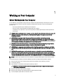
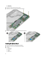
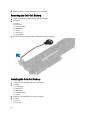
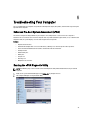
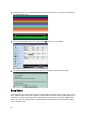
1
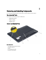
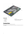
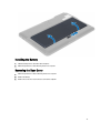
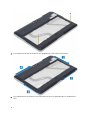
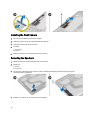
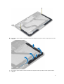
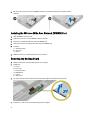
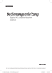
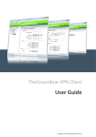
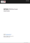
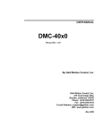
Dell Latitude 10 – ST2
Owner's Manual
Regulatory Model: T05G
Regulatory Type: T05G001
Notes, Cautions, and Warnings
NOTE: A NOTE indicates important information that helps you make better use of your computer.
CAUTION: A CAUTION indicates either potential damage to hardware or loss of data and tells you how to avoid the
problem.
WARNING: A WARNING indicates a potential for property damage, personal injury, or death.
© 2013 Dell Inc.
Trademarks used in this text: Dell™, the DELL logo, Dell Precision™, Precision ON™,ExpressCharge™, Latitude™, Latitude ON™,
OptiPlex™, Vostro™, and Wi-Fi Catcher™ are trademarks of Dell Inc. Intel®, Pentium®, Xeon®, Core™, Atom™, Centrino®, and Celeron®
are registered trademarks or trademarks of Intel Corporation in the U.S. and other countries. AMD® is a registered trademark and
AMD Opteron™, AMD Phenom™, AMD Sempron™, AMD Athlon™, ATI Radeon™, and ATI FirePro™ are trademarks of Advanced Micro
Devices, Inc. Microsoft®, Windows®, MS-DOS®, Windows Vista®, the Windows Vista start button, and Office Outlook® are either
trademarks or registered trademarks of Microsoft Corporation in the United States and/or other countries. Blu-ray Disc™ is a trademark
owned by the Blu-ray Disc Association (BDA) and licensed for use on discs and players. The Bluetooth® word mark is a registered
trademark and owned by the Bluetooth® SIG, Inc. and any use of such mark by Dell Inc. is under license. Wi-Fi® is a registered
trademark of Wireless Ethernet Compatibility Alliance, Inc.
2013 – 04
Rev. A02
Contents
Notes, Cautions, and Warnings...................................................................................................2
1 Working on Your Computer.......................................................................................................5
Before Working Inside Your Computer.....................................................................................................................5
Turning Off Your Computer.......................................................................................................................................6
After Working Inside Your Computer........................................................................................................................6
2 Overview.......................................................................................................................................7
Stylus........................................................................................................................................................................7
Stylus Information..............................................................................................................................................7
Calibrating the Stylus................................................................................................................................................7
Using a Stylus in a Tablet.........................................................................................................................................8
Using the Stylus as a Mouse..............................................................................................................................8
Using the Stylus or Finger on Touch Keyboard..................................................................................................8
Touch Keyboard.................................................................................................................................................8
Working with Files..............................................................................................................................................8
Entering Text......................................................................................................................................................9
Stylus Flicks........................................................................................................................................................9
Pen and Touch Settings...................................................................................................................................10
Touch Usage....................................................................................................................................................11
3 Removing and Installing Components...................................................................................13
Recommended Tools..............................................................................................................................................13
Internal and External View.....................................................................................................................................13
Removing the Battery.............................................................................................................................................14
Installing the Battery..............................................................................................................................................15
Removing the Base Cover.......................................................................................................................................15
Installing the Base Cover........................................................................................................................................17
Removing the Front Camera...................................................................................................................................17
Installing the Front Camera.....................................................................................................................................18
Removing the Speakers..........................................................................................................................................18
Installing the Speakers...........................................................................................................................................20
Removing the SmartCard Reader ..........................................................................................................................20
Installing the SmartCard Reader ............................................................................................................................21
Removing the Wireless Wide Area Network (WWAN) Card .................................................................................21
Installing the Wireless Wide Area Network (WWAN) Card ..................................................................................22
Removing the Docking Board.................................................................................................................................22
Installing the Docking Board..................................................................................................................................23
Removing the System Board...................................................................................................................................23
Installing the System Board....................................................................................................................................24
Removing the Rear Camera....................................................................................................................................25
Installing the Rear Camera.....................................................................................................................................25
Removing the Coin-Cell Battery..............................................................................................................................26
Installing the Coin-Cell Battery...............................................................................................................................26
4 System Setup.............................................................................................................................29
Entering System Setup (BIOS)................................................................................................................................29
System Setup Navigation.......................................................................................................................................29
Boot Menu..............................................................................................................................................................30
System Setup (BIOS) Options.................................................................................................................................30
5 Troubleshooting Your Computer.............................................................................................35
Enhanced Pre-boot System Assessment (ePSA)...................................................................................................35
Running the ePSA Diagnostic Utility.......................................................................................................................35
Beep Codes.............................................................................................................................................................36
LED Error Codes......................................................................................................................................................37
Troubleshooting the Wacom Digitizer....................................................................................................................38
Troubleshooting Steps.....................................................................................................................................38
6 Specifications............................................................................................................................39
7 Contacting Dell..........................................................................................................................43
Working on Your Computer
1
Before Working Inside Your Computer
Use the following safety guidelines to help protect your computer from potential damage and to help to ensure your
personal safety. Unless otherwise noted, each procedure included in this document assumes that the following
conditions exist:
•
You have performed the steps in Working on Your Computer.
•
You have read the safety information that shipped with your computer.
•
A component can be replaced or--if purchased separately--installed by performing the removal procedure in
reverse order.
WARNING: Before working inside your computer, read the safety information that shipped with your computer. For
additional safety best practices information, see the Regulatory Compliance Homepage at www.dell.com/
regulatory_compliance
CAUTION: Many repairs may only be done by a certified service technician. You should only perform
troubleshooting and simple repairs as authorized in your product documentation, or as directed by the online or
telephone service and support team. Damage due to servicing that is not authorized by Dell is not covered by your
warranty. Read and follow the safety instructions that came with the product.
CAUTION: To avoid electrostatic discharge, ground yourself by using a wrist grounding strap or by periodically
touching an unpainted metal surface, such as a connector on the back of the computer.
CAUTION: Handle components and cards with care. Do not touch the components or contacts on a card. Hold a
card by its edges or by its metal mounting bracket. Hold a component such as a processor by its edges, not by its
pins.
CAUTION: When you disconnect a cable, pull on its connector or on its pull-tab, not on the cable itself. Some
cables have connectors with locking tabs; if you are disconnecting this type of cable, press in on the locking tabs
before you disconnect the cable. As you pull connectors apart, keep them evenly aligned to avoid bending any
connector pins. Also, before you connect a cable, ensure that both connectors are correctly oriented and aligned.
NOTE: The color of your computer and certain components may appear differently than shown in this document.
To avoid damaging your computer, perform the following steps before you begin working inside the computer.
1.
Ensure that your work surface is flat and clean to prevent the computer cover from being scratched.
2.
Turn off your computer.
3.
If the computer is connected to a docking device (docked), undock it.
CAUTION: To disconnect a network cable, first unplug the cable from your computer and then unplug the
cable from the network device.
4.
Disconnect all network cables from the computer.
5.
Disconnect your computer and all attached devices from their electrical outlets.
6.
Turn the computer upside-down on a flat work surface.
5
NOTE: To avoid damaging the system board, you must remove the main battery before you service the
computer.
7.
Remove the main battery.
8.
Turn the computer top-side up.
9.
Press the power button to ground the system board.
CAUTION: To guard against electrical shock, always unplug your computer from the electrical outlet before
opening the display.
CAUTION: Before touching anything inside your computer, ground yourself by touching an unpainted metal
surface, such as the metal at the back of the computer. While you work, periodically touch an unpainted metal
surface to dissipate static electricity, which could harm internal components.
10. Remove any installed SmartCards from the slots.
Turning Off Your Computer
CAUTION: To avoid losing data, save and close all open files and exit all open programs before you turn off your
computer.
1.
Shut down the operating system:
–
Windows 8:
*
Using a touch-enabled device:
Swipe in from the right edge of the screen, opening the Charms menu and select Settings. Select
the
*
and then select Shut down
Using a mouse:
Point to upper-right corner of the screen and click Settings. Click on the
down.
2.
and then select Shut
Ensure that the computer and all attached devices are turned off. If your computer and attached devices did not
automatically turn off when you shut down your operating system, press and hold the power button for about 4
seconds to turn them off.
After Working Inside Your Computer
After you complete any replacement procedure, ensure you connect any external devices, cards, and cables before
turning on your computer.
CAUTION: To avoid damage to the computer, use only the battery designed for this particular Dell computer. Do not
use batteries designed for other Dell computers.
1.
Connect any external devices, such as a port replicator, battery slice, or media base, and replace any cards, such
as an ExpressCard.
2.
Connect any telephone or network cables to your computer.
CAUTION: To connect a network cable, first plug the cable into the network device and then plug it into the
computer.
3.
Replace the battery.
4.
Connect your computer and all attached devices to their electrical outlets.
5.
Turn on your computer.
6
Overview
2
Your Dell Latitude 10-ST2 tablet is built for business with easy management and security. It provides:
•
world class security
•
easy management
•
long term stability
It is shipped with Windows 8 operating system to fully utilize the touch experience.
NOTE: It is recommended that you immediately backup the operating system image using the USB device through
Dell Backup and Recovery (DBAR) application.
Stylus
The Latitude 10–ST2 uses several input devices, they are:
•
optional electrostatic pen (stylus)
•
external USB mouse/keyboard
Stylus Information
1. Stylus tip
2. Right-click pen button
3. Eraser pen button
Calibrating the Stylus
The stylus can function at the default calibration or at a calibration set by you or by another user. It is recommended that
you use the stylus only while it is calibrated to your personal calibration settings. Calibration optimizes stylus
performance for each user.
1.
Open Control Panel.
2.
Double-click Tablet PC Settings.
3.
On the Tablet PC Settings window, click Calibrate.
4.
On the Calibrate pen or touch input screens, select Pen input.
7
Using a Stylus in a Tablet
The stylus allows you to actively navigate through the menus. You can use it as a mouse and also as a pen.
Using the Stylus as a Mouse
You can use the stylus the same way you use a mouse or touch pad with a notebook computer. Holding the stylus near
the display makes a small cursor appear. Moving the stylus moves the cursor. Table 1 describes how to use the stylus.
Table 1. Electrostatic Pen Usage
Appearance
Action
Function
Gently tap the stylus tip on the screen of your
Tablet PC
Same as a single-click on a mouse.
Gently tap the stylus tip twice in quick succession
on the screen of your Tablet PC.
Same as a double-click on a mouse.
Touch the stylus on the screen and hold it in place Same as a right-click on a mouse.
momentarily until Windows draws a complete
circle around the cursor.
Using the Stylus or Finger on Touch Keyboard
The Touch Keyboard or Handwriting recognition makes it easy to enter text into your applications with the stylus or finer.
Applications like Windows Journal, allow you to write with the stylus directly into the application window.
Touch Keyboard
Some of the Windows text input boxes will bring out the Touch Keyboard automatically when you tap on the boxes.
When it does not come out, you can open the Touch Keyboard by clicking on the keyboard icon on the system toolbar.
The Touch Keyboard is like a standard keyboard will appear on the screen which can be used to enter text by tapping
the keys with your stylus pen or finger
Working with Files
You can open, delete, or move many files or folders at one time by selecting multiple items from a list.
1. Hover over one item at a time.
2. Select the check box that appears to the left of each item.
To turn check boxes on:
1. Open Control Panel.
8
2. Go to Folder options.
3. Click View.
4. Under Advanced settings , select the Use check boxes to select items check box, and then click OK.
Entering Text
You can use handwriting recognition application or the touch keyboard to enter text.
Table 2. Input Panel Icons
Icon
Name
Function
The touch keyboard is like a standard
keyboard, you can enter text by tapping
the keys with your stylus or finger.
The touch keyboard is like a standard
keyboard, you can enter text by tapping
the keys with your stylus or your thumb.
The writing pad and character pad
convert handwriting into typed text.
You can write continuously on the
writing pad, like writing on a piece of
lined paper. Use the character pad to
enter one character at a time. The
character pad converts your
handwriting to typed text, one letter,
number or symbol at a time, but does
not take the context of the full word
into account and does not take
advantage of the handwriting
dictionary. To switch to the character
pad in Input Panel, tap Tools, and then
Write character by character
To minimize the Touch keyboard, click
the minimize icon.
Stylus Flicks
Stylus flicks enable you to use the stylus to perform actions that normally require a keyboard, such as pressing <Page
Up> or using the directional arrow keys. Stylus flicks are quick, directional gestures. You can quickly draw a short line in
one of eight directions. When a stylus flick is recognized, the Tablet PC performs the action assigned.
9
Pen and Touch Settings
Using the stylus, you can adjust how quickly you tap the screen when you double-tap the screen. It also allows you
define the spatial tolerance.
The Press and Hold settings allow you to define the speed and the duration for a right-click action.
10
Touch Usage
One of the key advantages of the Tablet PC is the ability to easily switch from pen input to touch input.
When you use Touch Mode , a translucent image of a computer mouse, called the touch pointer, floats beneath your
finger. The touch pointer has left and right mouse buttons that you can tap with your finger. You use the area beneath
the buttons to drag the touch pointer.
To show the touch pointer, go to Control Panel → Pen and Touch and clicking on the Touch tab. In the Touch action
section, select the option Show visual feedback when touching the screen
11
12
Removing and Installing Components
3
This section provides detailed information on how to remove or install the components from your computer.
Recommended Tools
The procedures in this document may require the following tools:
•
Small flat-blade screwdriver
•
#0 Phillips screwdriver
•
#1 Phillips screwdriver
•
Small plastic scribe
Internal and External View
Figure 1. External View
1.
2.
3.
4.
5.
micro SIM card (located below the battery)
SmartCard reader slot
battery
Secure Digital (SD) card slot
fingerprint reader (optional)
13
Figure 2. Internal View
1.
2.
3.
4.
5.
docking board
coin-cell battery
speaker
system board
front camera
6. rear camera
7. SmartCard reader/WWAN card (WWAN card is
located below the SmartCard reader
Removing the Battery
1.
Follow the procedures in Before Working Inside Your Computer.
2.
Slide the battery release latch to the unlock position. Lift up the battery in an outward direction and remove it from
the computer.
14
Installing the Battery
1.
Slide the battery into its slot until it clicks into place.
2.
Follow the procedures in After Working Inside Your Computer.
Removing the Base Cover
1.
Follow the procedures in Before Working Inside Your Computer.
2.
Remove the battery.
3.
Remove the screws that secure the base cover to the computer.
15
4.
Pry and release the tabs that secure the base cover by following the arrow sequence in the diagram.
5.
Pry and lift the tabs that secure the base cover in the battery bay area in an upward direction. Pry and flip the base
cover.
16
6.
Lift the retention clasp in an upward direction and release the fingerprint reader cable outward to remove it from
the system board. Lift the base cover away from the computer.
Installing the Base Cover
1.
Attach the fingerprint reader flex cable from the base cover to the system board.
2.
Attach the base cover to the computer.
3.
Push the edges of the base cover into the securing clips until they are fully engaged.
4.
Tighten the screws to secure the base cover.
5.
Install the battery.
6.
Follow the procedures in After Working Inside Your Computer.
Removing the Front Camera
1.
Follow the procedures in Before Working Inside Your Computer.
2.
Remove the:
a) battery
b) base cover
3.
Lift up the connector latch and disconnect the camera cable. Remove the screw that secures the camera module
to the computer. Remove the camera module from the computer.
17
Installing the Front Camera
1.
Place the camera module in its slot on the computer.
2.
Tighten the screw to secure the camera module to the computer.
3.
Connect the camera cable to the connector.
4.
Install the:
a) base cover
b) battery
5.
Follow the procedures in After Working Inside Your Computer.
Removing the Speakers
1.
Follow the procedures in Before Working Inside Your Computer.
2.
Remove the :
a) battery
b) base cover
3.
Lift up the coin-cell battery from its slot and un-route its cabling from below the speaker. Disconnect the speaker
connector from the system board.
4.
Remove the screws that secure the speakers to the computer.
18
5.
Un-route the speaker cables on the right-hand side of the computer and lift up to release the right speaker from the
computer.
6.
Un-route the speaker cables on the left-hand side of the computer and lift up to release the left speaker from the
computer.
19
Installing the Speakers
1.
Place the right and the left speakers in their slot.
2.
Route the speaker cables on the chassis.
3.
Tighten the screws to secure the speakers to the chassis.
4.
Place the coin-cell battery in its slot and route the cables.
5.
Connect the speaker connector cable to its port on the system board.
6.
Install the :
a) base cover
b) battery
7.
Follow the procedures in After Working Inside Your Computer.
Removing the SmartCard Reader
NOTE: The SmarCard reader is an optional component.
1.
Follow the procedures in Before Working Inside Your Computer.
2.
Remove the :
a) battery
b) base cover
3.
20
Remove the screws that secure the SmartCard reader to the system board and lift in an upward direction to remove
it from the computer.
Installing the SmartCard Reader
1.
Place the SmartCard reader into its slot.
2.
Tighten the screws to secure the SmartCard reader to the system board.
3.
Install the :
a) base cover
b) battery
4.
Follow the procedures in After Working Inside Your Computer.
Removing the Wireless Wide Area Network (WWAN) Card
NOTE: The WWAN Card is an optional component.
1.
Follow the procedures in Before Working Inside Your Computer.
2.
Remove the :
a) battery
b) base cover
c) SmartCard reader
3.
Disconnect antennae connected to the WWAN card. Lift up the system board connector to release the WWAN
card.
21
4.
Disconnect the screws that secure the WWAN card to the system board and lift it up to remove it from the
computer.
Installing the Wireless Wide Area Network (WWAN) Card
1.
Slide the WWAN card into the slot.
2.
Tighten the screws to secure the WWAN card to the computer.
3.
Connect the system board side data cable to the WWAN card.
4.
Connect the antennae according to the color code on the WWAN card.
5.
Install the :
a) SmartCard reader
b) base cover
c) battery
6.
Follow the procedures in After Working Inside Your Computer.
Removing the Docking Board
1.
Follow the procedures in Before Working Inside Your Computer.
2.
Remove the:
a)
b)
c)
d)
e)
f)
battery
base cover
SmartCard reader
WWAN Card
speaker
front camera
3.
Lift up the connector latch and disconnect the docking board power flex cable from the connector.
4.
Remove the screws that secure the docking board to the computer.
22
5.
Remove the docking board from the computer and disconnect the home-button board cable.
Installing the Docking Board
1.
Connect the home-button board cable to the docking board and place the docking board in its slot in the computer.
2.
Tighten the screws to secure the docking board to the computer.
3.
Connect the docking board power flex cable to the connector.
4.
Install the:
a)
b)
c)
d)
e)
f)
5.
front camera
speaker
WWAN Card
SmartCard reader
base cover
battery
Follow the procedures in After Working Inside Your Computer.
Removing the System Board
1.
Follow the procedures in Before Working Inside Your Computer.
2.
Remove the:
a)
b)
c)
d)
e)
battery
base cover
SmartCard reader
WWAN card
speaker
23
f) front camera
g) docking board
3.
Disconnect the LVDS and docking board flex cables.
4.
Remove the screws that secure the system board to the computer.
5.
Lift up the system board at a 45° angle and pull it away from the computer.
Installing the System Board
1.
Place the system board in its compartment on the computer.
2.
Tighten the screws to secure the system board to the computer.
3.
Install the:
a) docking board
b) front camera
c) speaker
d) WWAN card
24
e) SmartCard reader
f) base cover
g) battery
4.
Follow the procedures in After Working Inside Your Computer.
Removing the Rear Camera
1.
Follow the procedures in Before Working Inside Your Computer.
2.
Remove the:
a) battery
b) base cover
c) SmartCard reader
d) WWAN Card
e) speaker
f) front camera
g) system board
3.
Remove the camera module from the system board.
Installing the Rear Camera
1.
Place the camera module in its slot on the system board.
2.
Install the:
a) system board
b) front camera
c) speaker
d) WWAN Card
e) SmartCard reader
f) base cover
g) battery
25
3.
Follow the procedures in After Working Inside Your Computer.
Removing the Coin-Cell Battery
1.
Follow the procedures in Before Working Inside Your Computer.
2.
Remove the:
a)
b)
c)
d)
e)
f)
g)
3.
battery
base cover
SmartCard reader
WWAN Card
speaker
front camera
system board
Disconnect the coin-cell battery cable and remove it from the system board.
Installing the Coin-Cell Battery
1.
Connect the coin-cell battery cable to the system board.
2.
Install the:
a)
b)
c)
d)
e)
system board
front camera
WWAN Card
SmartCard reader
speaker
3.
Replace the coin-cell battery in its slot on the computer.
4.
Install the:
a) battery
b) base cover
26
5.
Follow the procedures in After Working Inside Your Computer.
27
28
System Setup
4
System Setup enables you to manage your computer hardware and specify BIOS‐level options. From the System Setup,
you can:
•
Change the NVRAM settings after you add or remove hardware
•
View the system hardware configuration
•
Enable or disable integrated devices
•
Set performance and power management thresholds
•
Manage your computer security
Entering System Setup (BIOS)
NOTE: Before entering the System Setup, you must connect a USB Keyboard to the USB port located on the right
side of the computer or on the rear of the docking station if your computer is docked.
1.
Turn on (or restart) your computer.
2.
When the blue DELL logo is displayed, you must watch for the F2 prompt to appear.
3.
Once the F2 prompt appears, press <F2> immediately.
NOTE: The F2 prompt indicates that the keyboard has initialized. This prompt can appear very quickly, so you
must watch for it to display, and then press <F2> . If you press <F2> before you are prompted, this keystroke
will be lost.
4.
The System Setup screen is displayed.
5.
If you wait too long and the operating system logo appears, continue to wait until you see the Microsoft Windows
desktop. Then, shut down your computer and try again.
System Setup Navigation
Use the following options to navigate through the System Setup screens:
Keystroke
Action
< Esc >
Exit from current view or switch the current view to the Exit page in the System Setup.
<On Screen Keyboard Select this option to navigate the system setup using the on screen keyboard built into the
Icon>
tablet.
< Up Arrow > or <
Select an item to display.
Down Arrow > ( when
connected to an
optional external USB
keyboard)
< Left Arrow > or <
Right Arrow > ( when
Select a menu to display.
29
Keystroke
Action
connected to an
optional external USB
keyboard)
On Screen Mouse
Pointer
Use this to navigate the System Setup by using your finger or an interactive pen.
Apply Icon
Save current configuration.
Defaults Icon
Load setup defaults.
Exit Icon
Exits System Setup.
Boot Menu
Press <F12> when the Dell logo appears to initiate a one-time boot menu with a list of the valid boot devices for the
system. Hard Drive Network Diagnostics and Enter Setup options are included in this menu. The devices listed on the
boot menu depend on the bootable devices in the system. This menu is useful when you are attempting to boot to a
particular device or to bring up the diagnostics for the system. Using the boot menu does not make any changes to the
boot order stored in the BIOS.
System Setup (BIOS) Options
Table 3. System Information
Option
Function
BIOS Version
Displays the BIOS revision.
Service Tag
Displays the service tag of your tablet.
Asset Tag
Displays the asset tag of your computer.
Ownership Tag
Displays the ownership information.
Manufacture Date
Displays the date of manufacture.
Ownership Date
Displays the ownership date.
Memory Installed
Displays the memory installed on the computer.
Memory Available
Displays the memory available on the computer.
Memory Speed
Displays the memory speed.
Table 4. Battery Information
Option
Function
AC Adapter
Displays the AC Adapter information.
Battery Status
Displays the current battery status.
Battery Charge State
Displays if the battery is charging/discharging.
Battery Health
Displays the battery health.
30
Table 5. Boot Sequence
Option
Function
File Browser Add Boot Option
Displays the order that the BIOS searches devices when
trying to find an operating system to boot. A new device
can be added here.
File Browser Del Boot Option
A displayed boot device can be removed from the boot
order.
Table 6. Date/Time
Option
Function
System Date
Displays the system date.
System Time
Displays the system time.
Table 7. System Configuration
Option
Function
USB Configuration
Enables or Disables boot from a USB mass storage device.
Default : Enabled
Miscellaneous Devices
Allows you to enable or disable various on-board devices.
•
•
•
•
Enable/Disable Front Camera Device
Enable/Disable Rear Camera Device
Enable/Disable Media Card Device
Enable/Disable GPS
Table 8. Video
Option
Function
LCD Brightness
Displays the panel brightness when the ambient light
sensor is off.
•
•
Brightness on Battery
Brightness on AC
Table 9. Security
Option
Description
Admin Password
This field lets you set, change, or delete the administrator (admin) password (also
known as the setup password). The admin password enables several security
features.
The drive does not have a password set by default.
To add a new password:
•
•
•
Enter the old password
Enter the new password
Confirm the new password
31
Option
Description
Click OK after entering the password details.
System Password
Allows you to set, change, or delete the computer password (previously called the
primary password).
The drive does not have a password set by default.
To add a new password:
•
•
•
Enter the old password
Enter the new password
Confirm the new password
Click OK after entering the password details.
Strong Password
Enable strong password - This option is disabled by default.
Password Configuration
This field controls the minimum and maximum number of characters allowed for the
admin and system passwords. Changes to these fields are not active until they are
committed via the apply button or saving changes before exiting setup.
•
•
•
•
Password Change
Allows you to determine whether changes to the system and hard disk passwords are
permitted when an administrator password is set.
•
Non-Admin Setup Changes
Allow Non-Admin Password Changes (Default)
This option lets you determine whether changes to the setup options are permitted
when an administrator password is set.
•
TPM Security
Admin Password Min
Admin Password Max
System Password Min
System Password Max
Allow Wireless Switch Changes (Default)
This option lets you control whether the Trusted Platform Module (TPM) in the system
is enabled and visible to the operating system.
TPM Security (Default)
NOTE: Activation, deactivation, and clear options are not affected if you load the
setup program's default values. Changes to this option take effect immediately.
PTT
Allows you to enable or disable PTT Support.
•
•
Computrace (R)
This field lets you activate or disable the BIOS module interface of the optional
Computrace Service from Absolute Software.
•
•
•
32
PTT Security (Default)
Revoke Trust (Default)
Deactivate (Default)
Disable
Activate
Option
Description
Admin Setup Lockout
Allows you to enable or disable the option to enter setup when an admin password is
set.
•
Enable Admin Setup Lockout (Default)
Table 10. Secure Boot
Option
Function
Secure Boot
Enables or Disables the secure boot feature. Default :
Disabled
Expert Key Management
Allows you to manage all secure boot keys.
Table 11. Performance
Option
Description
Multi Core Support
Specifies whether the process will have one or all cores enabled. The performance of
some applications will improve with the additional cores.
•
•
•
Intel SpeedStep
All (Default)
1
2
Allows you to enable or disable the Intel SpeedStep mode of the processor.
•
C States Control
Enable Intel(R) SpeedStep (Default)
Allows you to enable or disable the additional processor sleep states.
•
Intel TurboBoost
C states (Default)
Allows you to enable or disable Intel TurboBoost mode of the processor.
•
Hyperthread Control
Enable Intel TurboBoost (Default) — Allows the Intel TurboBoost driver to
increase the performance of the CPU or graphics processor.
This options allows users to enable and disable the Hyperthread Control.
•
Hyperthread Control (selected by default)
Table 12. Power Management
Option
Description
AC Behavior
Allows the computer to power-uon automatically, when AC adapter is plugged. The
option is disabled.
•
Wake on LAN
Wake on AC
This option allows the computer to power up from the off state when triggered by a
special LAN signal. Wake-up from the Standby state is unaffected by this setting
and must be enabled in the operating system. This feature only works when the
computer is connected to AC power supply.
33
Option
Description
•
•
Disabled - Does not allow the system to power on by special LAN signals
when it receives a wake-up signal from the LAN or wireless LAN. (Default )
LAN Only - Allows the system to be powered on by special LAN signals.
Table 13. POST Behaviour
Option
Description
Adapter Warnings
Allows you to activate the adapter warning messages when certain power
adapters are used. The option is enabled by default.
•
POST Hotkeys
Enable Adapter Warnings
Specifies whether the sign-on screen displays a message, that displays the
keystroke sequence required to enter the BIOS Boot Option Menu.
•
Enable F12 Boot Option menu (Default).
Table 14. Virtualization Support
Option
Description
Virtualization
This option specifies whether a Virtual Machine Monitor (VMM) can utilize the
additional hardware capabilities provided by Intel Virtualization technology.
•
Enable Intel Virtualization Technology (Default)
Table 15. Wireless
Option
Description
Wireless Device Enable
Allows you to enable or disable the wireless devices
•
•
WLAN
Bluetooth
All options are enabled by default.
Table 16. Maintenance
Option
Description
Service Tag
Displays the service tag of your computer.
Asset Tag
Allows you to create a system asset tag if an asset tag is not already set. This
option is not set by default.
Table 17. System Logs
Option
Description
BIOS events
Displays the system event log and allows you to clear the log.
•
34
Clear Log
Troubleshooting Your Computer
5
You can troubleshoot your computer using indicators like Diagnostic Lights, Beep Codes, and Error Messages during the
operation of the computer.
Enhanced Pre-boot System Assessment (ePSA)
The ePSA is a diagnostic utility available on your computer. This utility includes a series of tests for a computer's
hardware. You can run these tests even if the computer lacks any media (hard drive, optical drive, etc.). If a ePSA-tested
component fails, the system displays an error code and generates a beep code.
Features
•
Graphical User Interface
•
Automatic Default Operation- runs test on all devices, allowing a user to interrupt and select any device
•
Checks the Master Boot Record for readiness to boot into a full OS environment
•
Tablet panel test
•
Video memory test
•
Battery test
•
Charger test
•
Event log scan
•
Multiprocessor cache test
Running the ePSA Diagnostic Utility
NOTE: The following steps can be used to run the ePSA diagnostic utility in DOS mode without using an external
keyboard.
1.
Power on the system and immediately press the Volume Up key to begin the tests.
2.
The computer will begin running the ePSA utility.
35
3.
During the testing process, you will be prompted to answer a YES or NO question. To respond, press Volume Up =
YES or Volume Down = NO.
4.
Press the Security Button (<Ctrl> + <Alt> + <Del>) to click OK once the tests are completed.
5.
The volume up and down buttons can also be used as the <Tab> key when switching between options.
Beep Codes
The computer may emit a series of beeps during start-up if the display cannot show errors or problems. These series of
beeps, called beep codes, identify various problems. The delay between each beep is 300 ms, the delay between each
set of beeps is 3 seconds, and the beep sound lasts 300 ms. After each beep and each set of beeps, the BIOS should
detect if the user presses the power button. If so, BIOS will jump out from looping and execute the normal shutdown
process and power system.
36
Code
Cause and Troubleshooting Steps
1
BIOS ROM checksum in progress or failure
System board failure, covers BIOS corruption or ROM error
2
No RAM detected
No memory detected
3
Chipset Error (North and South Bridge Chipset, DMA/IMR/ Timer Error) , Time-Of-Day Clock test
failure , Gate A20 failure , Super I/O chip failure , Keyboard controller test failure
System board failure
4
RAM Read/Write failure
Memory failure
5
Real-time clock power fail
CMOS battery failure
6
Video BIOS test failure
Video card failure
7
CPU - cache test failure
Processor failure
8
Display
Display failure
LED Error Codes
Diagnostic LED codes are communicated via the Power Button LED. The Power Button LED blinks the corresponding
LED codes for the corresponding fault condition. Example: For No Memory detected (LED code 2) , The Power Button
LED blinks two times followed by a pause, blinks two times, pause, etc. This pattern continues until the system is
powered off.
Code
Cause and Troubleshooting Steps
1
System board: BIOS ROM failure
System board failure, covers BIOS corruption or ROM error
2
Memory
No memory/RAM detected
3
Chipset Error (North and South Bridge Chipset, DMA/IMR/ Timer Error) , Time-Of-Day Clock test
failure , Gate A20 failure , Super I/O chip failure , Keyboard controller test failure
System board failure
4
RAM Read/Write failure
Memory failure
5
Real-time clock power fail
37
Code
Cause and Troubleshooting Steps
CMOS battery failure
6
Video BIOS test failure
Video card failure
7
CPU - cache test failure
Processor failure
8
Display
Display failure
Troubleshooting the Wacom Digitizer
The Wacom Tablet Settings applet is used to adjust several settings for the digitizer. Once the Wacom drivers are
loaded, an icon appears in the system tray.
Troubleshooting Steps
1. Check the system information to see how many touch points are detected.
–
Right click Computer and select Properties from the menu.
–
Number of touch points will appear in the information window.
NOTE: The touch points in the properties window indicate that the touch driver has been installed on the tablet. For
more information on the installed driver, refer to the steps below.
38
•
Open the Device Manager and check that the Digitizer is recognized by the tablet .
•
In order to verify this, navigate to Device Manager → Human Interface Devices → I2C HID Device. Right click
on the Detail tab and choose Hardware IDs.
•
Verify if the device description lists Wacom and also check if a yellow exclamation mark appears alongside it.
•
If the device is not recognized, check if it is displayed under Unknown Devices and update the driver for the
unknown device.
6
Specifications
NOTE: Offerings may vary by region. The following specifications are only those required by law to ship with your
computer. For more information regarding the configuration of your computer, click Start → Help and Support and
select the option to view information about your computer.
System Information
Chipset
Intel Atom Z2760
DRAM bus width
32-bit
Flash EPROM
SPI 4M bits
Processor
Type
Intel Atom Z2760
External bus frequency
800 MHz
Memory
Memory capacity
2 GB
Memory type
LPDDR2
Audio
Type
Dual channel I2S codec
Controller
Realtek ALC3261
Stereo conversion
24-bit
Interface:
Internal
I2 S audio interface
External
microphone-in and stereo headphones/speakers combo
connector
Speakers
2 x 1 W stereo speakers
Internal speaker amplifier
1 W per channel
Video
Video type
integrated
Data bus
internal
Video controller
Intel Graphics Media Accelerator
39
Communications
Network adapter
USB 2.0 based Gigabit LAN via dock
Wireless
mobile broadband card (optional)
Ports and Connectors
Audio
one microphone-in and stereo headphones/speakers combo
connector
Video
one mini HDMI connector
USB
one USB 2.0 connector
Memory card reader
one 3-in-1 memory card reader
Display
Type
HD IPS LED
Size
10.1 inches high definition (HD)
Dimensions:
Height
125.11 mm (4.93 inches)
Width
222.52 mm (8.76 inches)
Diagonal
255.28 mm (10.05 inches)
Active area (X/Y)
222.52 mm / 125.11 mm
Maximum resolution
1366 x 768 pixels
Maximum brightness
450 nits
Refresh rate
60 Hz
Minimum viewing angles:
Horizontal
80/80
Vertical
80/80
Pixel pitch
0.1629 x 0.1629
Battery
Type
2–cell lithium ion (30 WHr)
4–cell lithium ion (60 WHr)
Length
238.30 mm (9.38 inches)
238.30 mm (9.38 inches)
Height
5.48 mm (0.22 inch)
10.03 mm (0.39 inch)
Width
86.50 mm (3.40 inches)
86.50 mm (3.40 inches)
Weight
220.00 g (0.49 lb)
373.00 g (0.82 lb)
Voltage
7.4 VDC
7.4 VDC
Dimensions
40
Battery
Temperature range
Operating
0 °C to 50 °C (32° F to 158 °F)
0 °C to 50 °C (32 °F to 158 °F)
Non-Operating
-20 °C to 65 °C ( –4 °F to 149 °F)
-20 °C to 65 °C ( –4 °F to 149 °F)
Coin-cell battery
3 V CR2025 lithium ion
AC Adapter
Type
Input voltage
100 VAC to 240 VAC
Input current (maximum)
0.87 A
Input frequency
50 Hz to 60 Hz
Output power
30 W
Output current (30 W)
1.54 A
Rated output voltage
19 Vdc/1.58 A; 19.5 Vdc/1.54 A
Temperature range:
Operating
0 °C to 35 °C (32 °F to 95 °F)
Non-operating
–40 °C to 65 °C (–40 °F to 149 °F)
Physical
Height (with security)
10.50 mm to 13.40 mm (0.41 inch to 0.53 inch)
Width
274 mm (10.79 inches)
Depth
176.60 mm (6.95 inches)
Weight (minimum)
658 grams (1.51 lb)
Environmental
Temperature:
Operating
-25 °C to 85 °C
Storage
-40 °C to 85 °C
Relative humidity (maximum):
Operating
Operating 10% to 90% (noncondensing)
Storage
Storage 5% to 95% (noncondensing)
Altitude (maximum):
Operating
–16 m to 3048 m (–50 to 10,000 ft)
Non-operating
–15.2 m to 10,668 m (–50 ft to 35,000 ft)
Airborne contaminant level
G1 as defined by ISA-71.04–1985
41
42
Contacting Dell
7
NOTE: If you do not have an active Internet connection, you can find contact information on your purchase invoice,
packing slip, bill, or Dell product catalog.
Dell provides several online and telephone-based support and service options. Availability varies by country and
product, and some services may not be available in your area. To contact Dell for sales, technical support, or customer
service issues:
1.
Visit dell.com/support
2.
Select your support category.
3.
Verify your country or region in the Choose a Country/Region drop-down menu at the top of page.
4.
Select the appropriate service or support link based on your need.
43