1
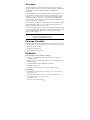
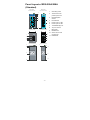
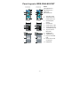
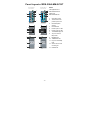
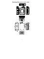
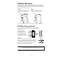
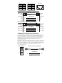
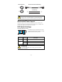
Moxa EtherDevice Switch
EDS-205A/208A Series
Hardware Installation Guide
Fourth Edition, October 2009
© 2009 Moxa Inc. All rights reserved.
Reproduction without permission is prohibited.
P/N: 1802002050023
Overview
The EDS-205A/208A series of industrial Ethernet switches are entry-level
industrial 5 and 8-port Ethernet switches that support IEEE 802.3, IEEE 802.3u,
and IEEE 802.3x with 10/100M, full/half-duplex, and MDI/MDIX
auto-sensing.
The EDS-205A/208A series provides 12/24/48 VDC (9.6 to 60VDC)/18 to 30
VAC redundant power inputs that can be connected simultaneously to a live
AC/DC power source. The switches are available with a standard operating
temperature range from -10 to 60°C, or with a wide operating temperature
range from -40 to 75°C, and IP30 metal housing makes them rugged enough
for any harsh industrial environment.
To provide greater versatility for use with applications from different industries,
the EDS-205A/208A also allow users to enable or disable broadcast storm
protection with DIP switches on the outer panel.
The EDS-205A/208A switches can be easily installed with DIN-Rail mounting
as well as distribution boxes. The DIN-rail mounting capability and IP30 metal
housing with LED indicators make the plug-and-play EDS-205A/208A
switches reliable and easy to use.
NOTE
Throughout this Hardware Installation Guide, we use EDS as an
abbreviation for Moxa EtherDevice Switch:
EDS = Moxa EtherDevice Switch
Package Checklist
Your EDS is shipped with the following items. If any of these items is missing
or damaged, please contact your customer service representative for assistance.
y
y
y
Moxa EtherDevice™ Switch
Hardware Installation Guide
Moxa Product Warranty booklet
Features
High Performance Network Switching Technology
y
EDS-205A: 10/100BaseT(X) (RJ45), 100 BaseFX (SC/ST connector,
multi/single-mode)
y
EDS-208A series: 10/100BaseT(X) (RJ45), 100 BaseFX (SC/ST connector,
multi/single-mode)
y
y
y
10/100M, Full/Half-Duplex, MDI/MDIX auto-sensing
IEEE 802.3/802.3u/802.3x
Store and Forward switching process type, 1024 address entries
Rugged Design
y
Redundant dual 12/24/48 VDC (9.6 to 60VDC) or 18 to 30 VAC at 47 to
63 Hz power input
y
Operating temperature range from -10 to 60°C ,or extended operating
temperature of -40 to 75°C for (-T) models.
y
y
IP30 metal housing
DIN-rail or panel mounting ability
-2-
Panel Layout of EDS-205A/208A
(Standard)
EDS-205A
Front Panel View
EDS-208A
Front Panel View
1.
2
5
6
2.
7
3.
Grounding screw
Terminal block for
power input P1/P2
7
8
8
9
4.
DIP Switches
5.
Power input P1 LED
6.
Power input P2 LED
7.
10/100BaseT(X) Port
8.
Top Panel View
TP port’s 10/100
Mbps LED
Top Panel View
9.
3
1
1
Heat dissipation
orifices
Model Name
10. Screw hole for wall
mounting kit
11. DIN-Rail Kit
2
2
3
4
4
Rear Panel View
2
Rear Panel View
1
2
1
10
10
11
11
10
10
-3-
Panel Layout of EDS-205A-M-SC/ST
EDS-205A-M-SC
Front Panel View
EDS-205A-M-ST
Front Panel View
NOTE:
The appearance of
2
5
6
2
5
6
EDS-205A-S-SC is
identical to
EDS-205A-M-SC.
7
7
8
8
1.
2.
10
11
9
Grounding screw
Terminal block for
power input P1/P2
10
11
3.
9
Heat dissipation
orifices
Top Panel View
Top Panel View
4.
DIP Switches
5.
Power input P1 LED
3
6.
Power input P2 LED
1
1
7.
10/100BaseT(X) Port
2
2
3
8.
TP port’s 10/100
Mbps LED
4
4
9.
Model Name
10. 100BaseFX Port
11. FX port’s 100 Mbps
Rear Panel View
Rear Panel View
2
2
1
LED
1
12
12
12. Screw hole for wall
mounting kit
13. DIN-Rail Kit
13
13
12
12
-4-
Panel Layout of EDS-208A-M-SC/ST
EDS-208A-M-SC
Front Panel View
EDS-208A-M-ST
Front Panel View
2
5
6
NOTE:
2
5
6
The appearance of
EDS-208A-S-SC is
10
7
10
7
identical to
11
8
11
8
EDS-208A-M-SC.
1.
9
9
2.
Grounding screw
Terminal block for
power input P1/P2
Top Panel View
3.
Top Panel View
Heat dissipation
orifices
4.
DIP Switches
1
1
5.
Power input P1 LED
2
2
3
4
3
4
6.
Power input P2 LED
7.
10/100BaseT(X) Port
8.
Rear Panel View
2
12
1
2
1
12
TP port’s 10/100
Mbps LED
Rear Panel View
9.
Model Name
10. 100BaseFX Port
11. FX port’s 100 Mbps
13
LED
13
12. Screw hole for wall
mounting kit
12
13. DIN-Rail Kit
12
-5-
Panel Layout of EDS-208A-MM-SC/ST
EDS-208A-MM-SC
Front Panel View
EDS-208A-MM-ST
Front Panel View
NOTE:
2
5
6
2
5
6
The appearance of
EDS-208A-SS-SC is
10
7
10
7
identical to
11
8
11
8
EDS-208A-MM-SC.
1.
9
9
2.
Grounding screw
Terminal block for
power input P1/P2
Top Panel View
3.
Top Panel View
Heat dissipation
orifices
1
1
2
2
3
4
3
4
4.
DIP Switches
5.
Power input P1 LED
6.
Power input P2 LED
7.
10/100BaseT(X) Port
8.
Rear Panel View
2
12
Rear Panel View
1
2
1
12
TP port’s 10/100
Mbps LED
9.
Model Name
10. 100BaseFX Port
11. FX port’s 100 Mbps
13
LED
13
12. Screw hole for wall
mounting kit
12
12
13. DIN-Rail Kit
-6-
Mounting Dimensions (unit = mm)
-7-
DIN-Rail Mounting
The aluminum DIN-rail attachment plate should already be fixed to the back
panel of the EDS when you take it out of the box. If you need to reattach the
DIN-rail attachment plate, make sure the stiff metal spring is situated towards
the top, as shown in the figures below.
STEP 1:
Insert the top of the DIN-Rail into
the slot just below the stiff metal
spring.
STEP 2:
The DIN-Rail attachment unit will
snap into place as shown below.
Metal
Spring
Metal
Spring
DIN-Rail
DIN-Rail
To remove the EDS from the DIN-Rail, simply reverse Steps 1 and 2 above.
Wall Mounting (optional)
For some applications, you will find it convenient to mount the
EDS-205A/208A on the wall, as shown in the following figures.
STEP 1: Remove the
aluminum DIN-Rail
attachment plate from the
EDS-205A/208A’s rear
panel, and then attach the
wall mount plates as shown
in the diagram at the right.
top
plate
⇒
STEP 2:
Mounting the EDS-205A/208A on the wall requires 4
screws. Use the switch, with wall mount plates attached,
as a guide to mark the correct locations of the 4 screws.
The heads of the screws should be less than 6.0 mm in
diameter, and the shafts should be less than 3.5 mm in
diameter, as shown in the figure at the right.
NOTE
bottom
plate
6.0 mm
3.5 mm
Before tightening the screws into the wall, make sure the screw
head and shank size are suitable by inserting the screw into one of
the keyhole-shaped apertures of the wall mounting plates.
Do not screw the screws in completely—leave about 2 mm to allow room for
sliding the wall mount panel between the wall and the screws.
-8-
STEP 3:
Once the screws are fixed on the wall, insert the four screw heads through the
large parts of the keyhole-shaped apertures, and then slide the
EDS-205A/208A downwards, as indicated. Tighten the four screws for added
stability.
⇒
Wiring Requirements
WARNING
Safety First!
Turn the power off before disconnecting modules or wires. The
correct power supply voltage is listed on the product label. Check
the voltage of your power source to make sure that you are using
the correct voltage. Do NOT use a voltage greater than what is
specified on the product label.
These devices must be supplied by a SELV source as defined in
the Low Voltage Directive 2006/95/EC and 2004/108/EC.
WARNING
Safety First!
Calculate the maximum possible current in each power wire and
common wire. Observe all electrical codes dictating the
maximum current allowable for each wire size.
If the current goes above the maximum ratings, the wiring could
overheat, causing serious damage to your equipment.
You should also pay attention to the following points:
y
Use separate paths to route wiring for power and devices. If power wiring
and device wiring paths must cross, make sure the wires are perpendicular
at the intersection point.
NOTE: Do not run signal or communications wiring and power wiring in
the same wire conduit. To avoid interference, wires with different signal
characteristics should be routed separately.
y
You can use the type of signal transmitted through a wire to determine
which wires should be kept separate. The rule of thumb is that wiring that
shares similar electrical characteristics can be bundled together.
y
y
Keep input wiring and output wiring separated.
It is strongly advised that you label wiring to all devices in the system when
necessary.
-9-
Grounding the EtherDevice Switch
Grounding and wire routing help limit the effects of noise due to
electromagnetic interference (EMI). Run the ground connection from the
ground screw to the grounding surface prior to connecting devices.
ATTENTION
This product is intended to be mounted to a well-grounded
mounting surface such as a metal panel.
Wiring the Redundant Power Inputs
The top two contacts and the bottom two contacts of the 4-contact terminal
block connector on the EDS’s top panel are used for the EDS’s two AC/DC
inputs. Top and front views of one of the terminal block connectors are shown
here.
STEP 1: Insert the negative/positive AC/DC
wires into the V-/V+ terminals.
Top View
STEP 2: To keep the AC/DC wires from pulling
loose, use a small flat-blade screwdriver to tighten
the wire-clamp screws on the front of the terminal
block connector.
STEP 3: Insert the plastic terminal block
connector prongs into the terminal block receptor,
which is located on EDS’s top panel.
Front View
ATTENTION
Before connecting the EtherDevice Switch to the AC/DC power
inputs, make sure the AC/DC power source voltage is stable.
Communication Connections
The EDS-205A models have 4 or 5 10/100BaseT(X) Ethernet ports, and 1 or 0
(zero) 100 BaseFX multi/single-mode (SC/ST-type connector) fiber ports. The
EDS-208A models have 6, 7 or 8 10/100BaseT(X) Ethernet ports, and 2, 1 or 0
(zero) 100 BaseFX multi/single-mode (SC/ST-type connector) fiber ports.
10/100BaseT(X) Ethernet Port Connection
The 10/100BaseT(X) ports located on the EDS’s front panel are used to
connect to Ethernet-enabled devices. Below we show pinouts for both MDI
(NIC-type) ports and MDI-X (HUB/Switch-type) ports, and also show cable
wiring diagrams for straight-through and cross-over Ethernet cables.
- 10 -
MDI Port Pinouts
Pin
1
2
3
6
MDI-X Port Pinouts
Pin
1
2
3
6
Signal
Tx+
TxRx+
Rx-
8-pin RJ45
Signal
Rx+
RxTx+
Tx-
1
8
RJ45 (8-pin) to RJ45 (8-pin) Straight-Through Cable Wiring
Straight-Through Cable
Switch Port
RJ45 Plug Pin 1
RJ45
Connector
Tx+
TxRx+
Rx-
NIC Port
RJ45
Connector
Cable Wiring
3
6
1
2
3
6
1
2
Rx+
RxTx+
Tx-
RJ45 (8-pin) to RJ45 (8-pin) Cross-Over Cable Wiring
Cross-Over Cable
Switch Port
(NIC Port)
RJ45 Plug Pin 1
RJ45
Connector
(Rx+)
(Rx-)
(Tx+)
(Tx-)
Tx+
TxRx+
Rx-
Switch Port
(NIC Port)
RJ45
Connector
Cable Wiring
3
6
1
2
1
2
3
6
Rx+
RxTx+
Tx-
(Tx+)
(Tx-)
(Rx+)
(Rx-)
100BaseFX Ethernet Port Connection
The concept behind the SC/ST port and cable is quite straightforward. Suppose
you are connecting devices I and II; contrary to electrical signals, optical
signals do not require a circuit in order to transmit data. Consequently, one of
the optical lines is used to transmit data from device I to device II, and the
other optical line is used transmit data from device II to device I, for
full-duplex transmission.
Remember to connect the Tx (transmit) port of device I to the Rx (receive) port
of device II, and the Rx (receive) port of device I to the Tx (transmit) port of
device II. If you make your own cable, we suggest labeling the two sides of the
same line with the same letter (A-to-A and B-to-B, as shown below, or
A1-to-A2 and B1-to-B2).
SC-Port Pinouts
SC-Port to SC-Port Cable Wiring
A
A
B
B
Tx
Cable Wiring
Rx
A
B
A
B
- 11 -
ST-Port Pinouts
ST-Port to ST-Port Cable Wiring
A
A
B
B
Tx
Cable Wiring
Rx
A
B
A
B
ATTENTION
This is a Class 1 Laser/LED product. To avoid causing serious
damage to your eyes, do not stare directly into the Laser Beam.
Redundant Power Inputs
Both power inputs can be connected simultaneously to live AC/DC power
sources. If one power source fails, the other live source acts as a backup, and
automatically supplies all of the EDS’s power needs.
DIP Switch Settings
EDS-205A/208A DIP Switches
1
ON
2
The default setting for each DIP Switch is OFF.
The following table explains the effect of setting
the DIP Switches to the ON positions.
DIP Switch
Setting
Description
Serves no function (reserved for future use).
-----ON
Enables broadcast storm protection
OFF
Disables broadcast storm protection
BSP
ATTENTION
To actively updated DIP switch settings, power off and then
power on the EDS.
- 12 -
LED Indicators
The front panel of the Moxa EtherDevice Switch contains several LED
indicators. The function of each LED is described in the table below.
LED
Color
P1
AMBER
P2
AMBER
State
On
Off
On
Off
On
10M
100M
Yellow
GREEN
Description
Power is being supplied to power input P1.
Power is not being supplied to power input
P1.
Power is being supplied to power input P2.
Power is not being supplied to power input
P2.
TP port’s 10 Mbps link is active.
Blinking Data is being transmitted at 10 Mbps.
Off
TP Port’s 10 Mbps link is inactive
On
TP port’s 100 Mbps link is active.
Blinking Data is being transmitted at 100 Mbps.
Off
100Base TP Port’s link is inactive.
Auto MDI/MDI-X Connection
The Auto MDI/MDI-X function allows users to connect the EDS’s
10/100BaseTX ports to any kind of Ethernet device, without needing to pay
attention to the type of Ethernet cable being used for the connection. This
means that you can use either a straight-through cable or cross-over cable to
connect the EDS to Ethernet devices.
Dual Speed Functionality and
Switching
The Moxa EtherDevice Switch’s 10/100 Mbps switched RJ45 port auto
negotiates with the connected device for the fastest data transmission rate
supported by both devices. All models of Moxa EtherDevice Switch are
plug-and-play devices, so that software configuration is not required at
installation, or during maintenance. The half/full duplex mode for the switched
RJ45 ports is user dependent and changes (by auto-negotiation) to full or half
duplex, depending on which transmission speed is supported by the attached
device.
Switching, Filtering, and Forwarding
Each time a packet arrives at one of the switched ports, a decision is made to
either filter or forward the packet. Packets with source and destination
addresses belonging to the same port segment will be filtered, constraining
those packets to one port, and relieving the rest of the network from the need to
process them. A packet with destination address on another port segment will
be forwarded to the appropriate port, and will not be sent to ports where it is
not needed. Packets that are used in maintaining the operation of the network
(such as the occasional multi-cast packet) are forwarded to all ports. The EDS
operates in the store-and-forward switching mode, which eliminates bad
packets and enables peak performance to be achieved when there is heavy
traffic on the network.
- 13 -
Switching and Address Learning
The EDS has an address table that can hold up to 1024 addresses, which makes
it suitable for use with large networks. The address tables are self-learning, so
that as nodes are added or removed, or moved from one segment to another, the
EDS automatically keeps up with new node locations. An address-aging
algorithm causes the least-used addresses to be deleted in favor of newer, more
frequently used addresses. To reset the address buffer, power down the unit and
then power it back up.
Auto-Negotiation and Speed Sensing
All of the EDS’s RJ45 Ethernet ports independently support auto-negotiation
for speeds in the 10BaseT and 100BaseTX modes, with operation according to
the IEEE 802.3u standard. This means that some nodes could be operating at
10 Mbps, while at the same time, other nodes are operating at 100 Mbps.
Auto-negotiation takes place when an RJ45 cable connection is made, and then
each time a LINK is enabled. The EDS advertises its capability for using either
10 Mbps or 100 Mbps transmission speeds, with the device at the other end of
the cable expected to advertise in a similar manner. Depending on what type of
device is connected, this will result in agreement to operate at a speed of either
10 Mbps or 100 Mbps. If an EDS RJ45 Ethernet port is connected to a
non-negotiating device, it will default to 10 Mbps speed and half-duplex mode,
as required by the IEEE 802.3u standard.
Specifications
Technology
Standards
Processing Type
Flow Control
Interface
RJ45 Ports
Fiber Ports
LED Indicators
DIP Switch
Optical Fiber
IEEE 802.3 for 10BaseT,
IEEE 802.3u for 100BaseT(X) and 100BaseFX,
IEEE 802.3x for Flow Control
Store and Forward
IEEE 802.3x flow control, back pressure flow
control
10/100BaseT(X) auto negotiation speed, F/H
duplex mode, and auto MDI/MDI-X connection
100BaseFX ports (SC/ST connector,
multi/single-mode)
P1, P2 (Power), 10/100M (TP port), and 100M
(Fiber port)
enable/disable broadcast storm protection
100BaseFX
Multi-mode
Single-mode
Wavelength
1300 nm
1310 nm
Max. TX
-10 dBm
0 dBm
Min. TX
-20 dBm
-5 dBm
RX Sensitivity
-32 dBm
-34 dBm
Link Budget
12 dB
29 dB
5 kma
Typical Distance
40
kmc
4 kmb
Saturation
-6 dBm
-3 dBm
a. using [50/125μm, 800 MHz*km] cable
b. using [62.5/125μm, 500 MHz*km] cable
c. using [9/125 μm, 3.5 PS/(nm*km)] cable
- 14 -
Power
Input Voltage
Input Current @ 24VDC
12/24/48 VDC (9.6 to 60 VDC),
18 to 30VAC (47 to 63 Hz)
0.1 A (EDS-205A)
0.11 A (EDS-205A-M/S)
0.13 A (EDS-208A)
0.17 A (EDS-208A-M/S)
0.22 A (EDS-208A-MM/SS)
Removable 4-contact terminal block
1.1 A
Connection
Overload Current
Protection
Reverse Polarity Protection Present
Physical Characteristics
Housing
IP30 protection, metal case
Dimensions
EDS-208A Series: 50 x 115 x 70 mm
EDS-205A: 30 x 115 x 70 mm
Weight
EDS-208A Series: 275 g
EDS-205A: 175 g
Installation
DIN-Rail Mounting, Wall Mounting
(with optional kit)
Environmental Limits
Operating Temperature
-10 to 60°C (14 to 140°F)
-40 to 75°C (-40 to 167°F) for -T models
Storage Temperature
-40 to 85°C (-40 to 185°F)
Ambient Relative Humidity 5 to 95% (non-condensing)
Regulatory Approvals
Safety
UL508 (pending)
Hazardous Location
UL/cUL Class I, Division 2, Groups A, B, C, and
D; ATEX Class I, Zone 2, Ex nC nL IIC T4
(Pending)
EMI
FCC Part 15, CISPR (EN55022) class A
EMS
EN61000-4-2 (ESD), Level 3
EN61000-4-3 (RS), Level 3
EN61000-4-4 (EFT), Level 3
EN61000-4-5 (Surge), Level 3
EN61000-4-6 (CS), Level 3
EN61000-4-8
EN61000-4-11
Shock
IEC 60068-2-27
Freefall
IEC 60068-2-32
Vibration
IEC 60068-2-6
5 years
WARRANTY
- 15 -
Technical Support Contact Information
www.moxa.com/support
Moxa Americas:
Toll-free: 1-888-669-2872
Tel:
+1-714-528-6777
Fax:
+1-714-528-6778
Moxa Europe:
Tel:
+49-89-3 70 03 99-0
Fax:
+49-89-3 70 03 99-99
Moxa Asia-Pacific:
Tel:
+886-2-8919-1230
Fax:
+886-2-8919-1231
Moxa China (Beijing office):
Tel:
+86-10-6872-3959/60/61
Fax:
+86-10-6872-3958
- 16 -