1
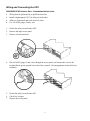
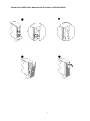
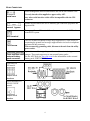
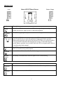
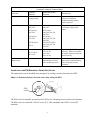
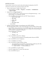
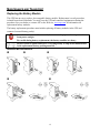
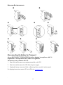
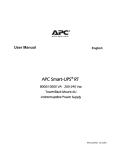
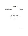
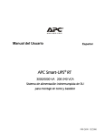
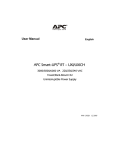
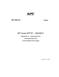
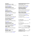
User Manual English Smart-UPS® RT 3000/5000/6000 VA 200-240 Vac Tower/Rack Mount 3U Uninterruptible Power Supply © 2012 APC by Schneider Electric. APC, the APC logo, and Smart-UPS are owned by Schneider Electric Industries S.A.S., American Power Conversion Corporation, or affiliated companies. All other trademarks are the property of their respective owners. 990-1289F 01/2012 Introduction The APC by Schneider Electric Smart-UPS RT is a high-performance, uninterruptible power supply (UPS) that provides protection for electronic equipment from utility power blackouts, brownouts, sags and surges. The UPS filters small utility line fluctuations and isolates electronic equipment from large disturbances by internally disconnecting from utility line power. The UPS provides continuous power from the internal battery until utility power returns to safe levels or the battery is fully discharged. INSTALLATION Read the Safety Guide before installing the UPS. Unpacking Inspect the UPS upon receipt. Notify the carrier and dealer if there is damage. The packaging is recyclable; save it for reuse or dispose of it properly. Check the package contents: UPS (with battery modules disconnected) Front bezel Literature kit containing: Product documentation, Safety Guide, and Warranty Information Smart-UPS RT User Manuals CD Software CD Serial cable 3000 VA XLI models: two output power cords, two input power cords 5000/6000 VA XLI models: four output power cords, Network Management Card documentation Specifications TEMPERATURE OPERATING STORAGE 32° to 104° F (0° to 40° C) 5° to 113° F (-15° to 45° C) charge the UPS battery every six months MAXIMUM ELEVATION OPERATING STORAGE 10,000 ft (3,000 m) 50,000 ft (15,240 m) HUMIDITY 0 to 95% relative humidity WEIGHT UPS UPS WITH PACKAGING 120 lbs (55 kg) 140 lbs (64 kg) . 1 This unit is designed for indoor use only. Select a location sturdy enough to handle the weight. Do not operate the UPS where there is excessive dust or the temperature and humidity are outside the specified limits. Ensure that the air vents on the front and rear of the UPS are not blocked. Wiring and Connecting the UPS 5000/6000 VA XLI MODELS ONLY: HARDWIRING INSTRUCTIONS Wiring must be performed by a qualified electrician. Install a high magnetic 30/32 A utility circuit breaker. Adhere to all national and local electrical codes. Use #10 AWG gauge (5 mm2) wire. 1. 2. 3. Switch the utility circuit breaker OFF. Remove the input access panel. Remove circular knockout. 4. Run #10 AWG gauge (5 mm2) wire through the access panel, and connect the wires to the terminal block (green: ground, brown: hot, blue: neutral). Use an appropriate strain relief (not included). 5. 6. 7. Switch the utility circuit breaker ON. Check line voltages. Replace the access panel. 2 CONNECTING THE BATTERY MODULES AND ATTACHING THE FRONT BEZEL . 3 BASIC CONNECTORS Power management software and interface kits can be used with the UPS. Use only interface kits supplied or approved by APC. serial com Any other serial interface cable will be incompatible with the UPS connector. Manual bypass enables the user to manually put connected equipment into bypass mode. normal bypass Emergency Power Off terminal allows the user to connect the UPS to the central EPO system. EPO terminal TVSS screw external battery pack connector The UPS features a transient voltage surge-suppression (TVSS) screw for connecting the ground lead on surge suppression devices such as telephone and network line protectors. When connecting grounding cable, disconnect the unit from the utility power outlet. Optional external battery packs provide extended runtime during power outages. These units support up to ten external battery packs. See the APC Web site, www.apc.com for the information on the external battery pack, SURT192XLBP. 5000/6000 VA XLI models output circuit breakers 3000/5000/6000 VA XLJ/XLT/XLTW models output circuit breaker 4 CONNECTING EQUIPMENT AND POWER TO THE UPS 1. 2. Connect equipment to the UPS (cables not included for XLJ/XLT/XLTW models). Avoid using extension cords. 3000 VA XLJ/XLT/XLTW/XLI and 5000/6000 VA XLJ/XLT/XLTW models: Using a power cord, plug the UPS into a two-pole, three-wire, grounded receptacle only. 3. 4. 5. 5000/6000 VA XLJ and 6000 VA XLT models: To draw full power from the UPS have a qualified electrician cut off the input plug and hardwire the UPS to the appropriate power panel. Turn on all connected equipment. To use the UPS as a master ON/OFF switch, ensure all connected equipment is switched ON. The equipment will not be powered until the UPS is turned on. button on the front panel. To power up the UPS press the The UPS battery charges when it is connected to utility power. The battery charges to 90% capacity during the first three hours of normal operation. Do not expect full battery run capability during this initial charge period. For additional computer system security, install PowerChute Business Edition Smart-UPS monitoring software. OPTIONS Refer to the APC Web site, www.apc.com for available accessories. External Battery Pack SURT192XLBP Rail Kit SURTRK2 Isolation Transformer Service Bypass Panel . 5 OPERATION SMART-UPS RT FRONT DISPLAY Load Battery Charge Indicator Description Online The Online LED illuminates when the UPS is drawing utility power and performing double conversion to supply power to connected equipment. On Battery The UPS is supplying battery power to the connected equipment. Bypass The Bypass LED illuminates indicating that the UPS is in bypass mode. Utility power is sent directly to connected equipment during bypass mode operation. Bypass mode operation is the result of an internal UPS fault, an overload condition or a user initiated command either through an accessory or the manual bypass switch. Battery operation is not available while the UPS is in bypass mode. Refer to Troubleshooting in this manual. Fault The UPS detects an internal fault. Refer to Troubleshooting in this manual. Overload An overload condition exists. See Troubleshooting. Replace Battery The battery is disconnected or must be replaced. See Troubleshooting. Feature Function Power On Press this button to turn on the UPS. (See below for additional capabilities.) Power Off Press this button to turn off the UPS. 6 Feature Function Cold Start When there is no utility power and the UPS is off, press and hold the power up the UPS and connected equipment. button to The UPS will emit two beeps. During the second beep, release the button. Self-Test Automatic: The UPS performs a self-test automatically when turned on, and every two weeks thereafter (by default). During the self-test, the UPS briefly operates the connected equipment on battery. Manual: Press and hold the Diagnostic Utility Voltage button for a few seconds to initiate the self-test. The UPS has a diagnostic feature that displays the utility voltage. Plug the UPS into the normal utility power. The UPS starts a self-test as part of this procedure. The self-test does not affect the voltage display. Press and hold the button to view the utility voltage bar graph display. After a few seconds the five-LED, Battery Charge display on the right of the front panel shows the utility input voltage. Refer to the figure at left for the voltage reading (values are not listed on the UPS). The display indicates the voltage is between the displayed value on the list and the next higher value. On Battery Operation The UPS switches to battery operation automatically if the utility power fails. While running on battery, an alarm beeps four times every 30 seconds. button to silence this alarm. If the utility power does not return, the UPS continues to Press the supply power to the connected equipment until the battery is fully discharged. When 2 minutes of run time remain the UPS emits a continuous beeping. If PowerChute is not being used, files must be manually saved and the computer must be turned off before the UPS fully discharges the battery. The UPS battery life differs based on usage and environment. Refer to www.apc.com, for on battery runtimes. . 7 USER CONFIGURABLE ITEMS NOTE: SETTINGS ARE MADE THROUGH SUPPLIED POWERCHUTE SOFTWARE OPTIONAL SMART SLOT ACCESSORY CARDS OR TERMINAL MODE. FACTORY DEFAULT USER SELECTABLE CHOICES Automatic Self-Test Every 14 days (336 hours) Every 7 days(168 hours), 14 days (336 hours) On Startup Only, No Self-Test Set the interval at which the UPS will execute a self-test. UPS ID UPS_IDEN Up to eight characters to define the UPS Uniquely identify the UPS, (i.e. server name or location) for network management purposes. Date of Last Battery Replacement Manufacture Date Date of Battery Replacement mm/dd/yy Reset this date when you replace the battery modules. Minimum Capacity Before Return from Shutdown 0 percent 0, 15, 25, 35, 50, 60, 75, 90 percent Following a low-battery shutdown, the battery modules will be charged to the specified percentage before powering connected equipment. Alarm Delay After Line Failure 5 second delay 5 or 30 second delay At Low Battery Never Mute ongoing alarms or disable all alarms permanently. Shutdown Delay 20 seconds 0, 20, 60, 120, 240, 480, 720, 960 seconds Set the interval between the time when the UPS receives a shutdown command and the actual shutdown. Duration of Low Battery Warning. 2 minutes PowerChute software provides automatic, unattended shutdown when approximately 2 minutes of battery operated runtime remains. 2, 5, 7, 10, 12, 15, 18, 20 minutes The low battery warning beeps are continuous when two minutes of run time remain. Change the warning interval default to a higher setting if the operating system requires a longer interval for shutdown. Synchronized Turn-on Delay 0 seconds 0, 20, 60, 120, 240, 480, 720, 960 seconds The UPS will wait the specified time after the return of utility power before turn-on (to avoid branch circuit overload). High Bypass Point +10% of output voltage setting +5%, +10%, +15%, +20% Maximum voltage that the UPS will pass to connected equipment during internal bypass operation. FUNCTION 8 DESCRIPTION NOTE: SETTINGS ARE MADE THROUGH SUPPLIED POWERCHUTE SOFTWARE OPTIONAL SMART SLOT ACCESSORY CARDS OR TERMINAL MODE. FACTORY DEFAULT USER SELECTABLE CHOICES Low Bypass Point -30% of output voltage setting -15%, -20%, -25%, -30% Minimum voltage that the UPS will pass to connected equipment during internal bypass operation. Output Voltage XLJ models: 200 VAC XLT models: 208 VAC XLJ models: 200 VAC XLT models: 200, 208, 220, 230, 240 VAC XLI models: 200, 208, 220, 230, 240 VAC XLT/XLTW models: 200, 208, 220, 230, 240 VAC Allows the user to select the UPS output voltage while online. FUNCTION XLI models: 230 VAC XLTW models: 220 V DESCRIPTION Output Frequency Automatic 50 ± 3 Hz or 60 ± 3 Hz 50 ± 3 Hz 50 ± 0.1 Hz 60 ± 3 Hz 60 ± 0.1 Hz Sets the allowable UPS output frequency. Whenever possible, the output frequency tracks the input frequency. Number of Battery Packs 1 Number of Connected Internal Battery Packs, (two modules per pack) Defines the number of internal and external connected battery packs for proper run time prediction. CONNECTING THE EPO (EMERGENCY POWER OFF) OPTION The output power can be disabled in an emergency by closing a switch connected to the EPO. Adhere to National and local electrical codes when wiring the EPO. EPO switch The EPO switch is internally powered by the UPS for use with non-powered switch circuit breakers. The EPO circuit is considered a Class 2 circuit, (UL, CSA standards) and a SELV circuit (IEC standard). . 9 Both Class 2 and SELV circuits must be isolated from all primary circuitry. Do not connect any circuit to the EPO terminal block unless it can be confirmed that the circuit is Class 2 or SELV. If circuit standard cannot be confirmed, use a contact closure switch. Use one of the following cable types to connect the UPS to the EPO switch: CL2: Class 2 cable for general use CL2P: Plenum cable for use in ducts, plenums, and other spaces used for environmental air. CL2R: Riser cable for use in a vertical run in a floor to floor shaft. CLEX: Limited use cable for use in dwellings and for use in raceways. For installation in Canada: Use only CSA certified, type ELC (extra-low voltage control cable). TERMINAL MODE TO CONFIGURE UPS PARAMETERS 3000 VA models: Terminal Mode is a menu driven interface that enables enhanced configuration of the UPS. Connect the serial cable to the serial com connector on the back of the UPS. 1. EXIT the PowerChute Business Edition using the following steps: From the Desktop, go to Start => Settings => Control Panel => Administrative Tools => Services. Select PCBE Server and PCBE Agent – right click the mouse and select Stop. Open a terminal program. Example: HyperTerminal From the Desktop, go to Start => Programs => Accessories => Communication =>HyperTerminal. Double-click on the HyperTerminal icon. Follow the prompts to choose a name and select an icon. Disregard the message, “...must install a modem,” if it is displayed. Click OK. Select the COM port that is connected to your UPS. The port settings are: bits per second - 2400 data - bits 8 parity - none stop bit - 1 flow control - none Press ENTER Example for setting the number of external battery packs (SURT192XLBP): Once the blank terminal window is open, follow these steps to enter the number of battery packs: Press ENTER to initiate terminal mode. Follow the prompts: Press 1 to modify UPS Settings. Press e (or E) to modify the number of battery packs. Enter the number of battery packs, including the internal battery pack (Number of packs: 1= internal battery module, 2 = 1 SURT192XLBP, 3 = 2 SURT192XLBP, etc.). Press ENTER. Follow the prompts. Exit the terminal program. 2. 3. 4. 5. 10 5000/6000 VA models: Terminal Mode is a menu driven interface that enables enhanced configuration of the UPS. Connect the serial cable to the serial port on the back of the UPS. 1. Open a terminal program. Example: HyperTerminal From the Desktop, go to Start => Programs => Accessories => Communication =>HyperTerminal. 2. Double-click on the HyperTerminal icon. Follow the prompts to choose a name and select an icon. Disregard the message, “...must install a modem,” if it is displayed. Click OK. Select the COM port that is connected to your UPS. The port settings are: bits per second - 2400 data - bits 8 parity - none stop bit - 1 flow control - none Press ENTER 3. Example for setting the number of external battery packs (SURT192XLBP): Once the blank terminal window is open, follow these steps to enter the number of battery packs: Press ENTER to initiate terminal mode. Press ENTER multiple times, until the prompt User Name: is displayed. Follow the prompts. Type slowly, waiting until each character appears on the screen prior to typing the next character. Network Management Card defaults: User Name: apc Password: apc Press 1 and ENTER to select Device Manager. Select the model by entering the corresponding number, then press ENTER. Press 3 and ENTER to select Configuration. Press 1 and ENTER to select Battery. Press 2 and ENTER to change the Battery Settings. Type in the number of external battery packs (four battery modules per pack), then press ENTER. (Number of packs: 1= internal battery module, 2 = 1 SURT192XLBP, 3 = 2 SURT192XLBP, etc.) Press 3 and ENTER to accept the changes. Press ESC multiple times (5) to return to the main menu. Press 4 and ENTER to log out. . 11 MAINTENANCE AND TRANSPORT Replacing the Battery Module This UPS has an easy to replace, hot-swappable battery module. Replacement is a safe procedure, isolated from electrical hazards. You may leave the UPS and connected equipment on during the procedure. See your dealer or contact APC at the Web site, www.apc.com for information on replacement battery modules. The battery replacement procedure must include replacing all battery modules in the UPS and connected external battery pack(s). Once the battery(s) are disconnected, the connected equipment is not protected from power outages. Be careful during battery replacement, the battery modules are heavy. Be sure to deliver spent batteries to a recycling facility or ship to the manufacturer in the replacement battery packing material. REMOVING BATTERY MODULES 12 REPLACING BATTERY MODULES Disconnecting the Battery for Transport Always DISCONNECT THE BATTERY(s) before shipping in compliance with U.S. Department of Transportation (DOT) and IATA regulations. The battery(s) may remain in the UPS. 1. Shut down and disconnect any equipment attached to the UPS. 2. Shut down and disconnect the UPS from the power supply. 3. Unplug the battery connectors. Refer to Replacing Battery modules in this manual. For shipping instructions contact APC at the Web site, www.apc.com. . 13 TROUBLESHOOTING, SERVICE, AND WARRANTY INFORMATION Use the table below to solve minor installation and operation problems. Refer to the APC Web site, www.apc.com for assistance with complex UPS problems. PROBLEM AND POSSIBLE CAUSE SOLUTION UPS WILL NOT TURN ON Battery not connected properly. button not pushed. Check that the battery connectors are fully engaged. Press the button once to power the UPS and the connected equipment. UPS not connected to utility power supply. Check that the power cable from the UPS to the utility power supply is securely connected at both ends. Very low or no utility voltage. Check the utility power supply to the UPS by plugging in a table lamp. If the light is very dim, have the utility voltage checked. UPS WILL NOT TURN OFF button not pushed. Internal UPS fault. Press the button once to turn the UPS off. Do not attempt to use the UPS. Unplug the UPS and have it serviced immediately. UPS BEEPS OCCASIONALLY Normal UPS operation when running on battery. None. The UPS is protecting the connected equipment. UPS DOES NOT PROVIDE EXPECTED BACKUP TIME The UPS battery(s) are weak due to a recent outage or battery(s) are near the end of their service life. Charge the battery(s). Battery modules require recharging after extended outages. They wear faster when put into service often or when operated at elevated temperatures. If the battery(s) are near the end of their service life, consider replacing the battery(s) even if the Replace Battery LED is not illuminated. FRONT PANEL LEDS FLASH SEQUENTIALLY The UPS has been shut down remotely through software or an optional accessory card. None. The UPS will restart automatically when utility power returns. ALL LEDS ARE OFF AND THE UPS IS PLUGGED INTO A WALL OUTLET The UPS is shut down and the battery is discharged from an extended outage. None. The UPS will return to normal operation when the power is restored and the battery has a sufficient charge. BYPASS AND OVERLOAD LEDS ILLUMINATE, UPS EMITS A SUSTAINED ALARM TONE The UPS is overloaded The connected equipment exceeds the specified “maximum load” as defined in Specifications on the APC Web site, www.apc.com. The alarm remains on until the overload is removed. Disconnect nonessential equipment from the UPS to eliminate the overload condition. 14 PROBLEM AND POSSIBLE CAUSE SOLUTION BYPASS LED ILLUMINATES The bypass switch has been turned on manually or through an accessory. If bypass is the chosen mode of operation, ignore the illuminated LED. If bypass is not the chosen mode of operation move the bypass switch on the back of the UPS, to the normal position. FAULT AND OVERLOAD LEDS ILLUMINATE, UPS EMITS A SUSTAINED ALARM TONE The UPS has ceased sending power to connected equipment. The connected equipment exceeds the specified “maximum load” as defined in Specifications on the APC Web site, www.apc.com. Disconnect nonessential equipment from the UPS to eliminate the overload condition. Press the OFF button, then the ON button to restore power to connected equipment. FAULT LED ILLUMINATES Internal UPS fault. Do not attempt to use the UPS. Turn the UPS off and have it serviced immediately. REPLACE BATTERY LED ILLUMINATES Replace Battery LED flashes and short beep is emitted every two seconds to indicate the battery is disconnected. Check that the battery connectors are fully engaged. Weak battery. Allow the battery to recharge for 24 hours. Then, perform a self-test. If the problem persists after recharging, replace the battery. Failure of a battery self-test. The UPS emits short beeps for one minute and the Replace Battery LED illuminates. The UPS repeats the alarm every five hours. Perform the self-test procedure after the battery has charged for 24 hours to confirm the Replace Battery condition. The alarm stops and the LED clears if the battery passes the self-test. UPS OPERATES ON BATTERY ALTHOUGH NORMAL LINE VOLTAGE EXISTS Very high, low, or distorted line voltage. Inexpensive fuel powered generators can distort the voltage. Move the UPS to a different outlet on a different circuit. Test the input voltage with the utility voltage display. DIAGNOSTIC UTILITY VOLTAGE All five LEDs are illuminated The line voltage is extremely high and should be checked by an electrician. There is no LED illumination If the UPS is plugged into a properly functioning utility power outlet, the line voltage is extremely low. ONLINE LED There is no LED illumination The UPS is running on battery, or it is not turned on. The LED is blinking The UPS is running an internal self-test. . 15 Service If the UPS requires service do not return it to the dealer. Follow these steps: 1. Review the problems discussed in the Troubleshooting section of this manual to eliminate common problems. 2. If the problem persists, contact APC Customer Support through the APC Web site, www.apc.com. Note the model number of the UPS, the serial number located on the back of the unit, and the date purchased. If you call APC Customer Support, a technician will ask you to describe the problem and attempt to solve it over the phone. If this is not possible, the technician will issue a Returned Material Authorization Number (RMA#). If the UPS is under warranty, repairs are free. 3. Procedures for servicing or returning products may vary internationally. Refer to the APC Web site for country specific instructions. Pack the UPS in its original packaging. If the original packing is not available, refer to the APC Web site, www.apc.com for information about obtaining a new set. Pack the UPS properly to avoid damage in transit. Never use Styrofoam beads for packaging. Damage sustained in transit is not covered under warranty. Always DISCONNECT THE BATTERY(S) before shipping in compliance with U.S. Department of Transportation (DOT) and IATA regulations. The battery(s) may remain in the UPS. 4. Mark the RMA# on the outside of the package. 5. Return the UPS by insured, prepaid carrier to the address given to you by Customer Support. Limited Warranty American Power Conversion (APC) warrants its products to be free from defects in materials and workmanship for a period of two years from the date of purchase. Its obligation under this warranty is limited to repairing or replacing, at its own sole option, any such defective products. To obtain service under warranty you must obtain a Returned Material Authorization (RMA) number from customer support. Products must be returned with transportation charges prepaid and must be accompanied by a brief description of the problem encountered and proof of date and place of purchase. This warranty does not apply to equipment that has been damaged by accident, negligence, or misapplication or has been altered or modified in any way. This warranty applies only to the original purchaser who must have properly registered the product within 10 days of purchase. EXCEPT AS PROVIDED HEREIN, AMERICAN POWER CONVERSION MAKES NO WARRANTIES, EXPRESSED OR IMPLIED, INCLUDING WARRANTIES OF MERCHANTABILITY AND FITNESS FOR A PARTICULAR PURPOSE. Some states do not permit limitation or exclusion of implied warranties; therefore, the aforesaid limitation(s) or exclusion(s) may not apply to the purchaser. EXCEPT AS PROVIDED ABOVE, IN NO EVENT WILL APC BE LIABLE FOR DIRECT, INDIRECT, SPECIAL, INCIDENTAL, OR CONSEQUENTIAL DAMAGES ARISING OUT OF THE USE OF THIS PRODUCT, EVEN IF ADVISED OF THE POSSIBILITY OF SUCH DAMAGE. Specifically, APC is not liable for any costs, such as lost profits or revenue, loss of equipment, loss of use of equipment, loss of software, loss of data, costs of substitutes, claims by third parties, or otherwise. 16 REGULATORY Radio Frequency Warnings This equipment has been tested and found to comply with the limits for a Class A digital device, pursuant to part 15 of the FCC Rules. These limits are designed to provide reasonable protection against harmful interference when the equipment is operated in a commercial environment. This equipment generates, uses, and can radiate radio frequency energy and, if not installed and used in accordance with the instruction manual, may cause harmful interference to radio communications. Operation of this equipment in a residential area is likely to cause harmful interference. The user is responsible for correcting the interference. Shielded signal cables must be used with this product to ensure compliance with the Class A FCC limits. APC Worldwide Customer Support Customer support for this or any other APC product is available at no charge in any of the following ways: Refer to the APC Web site to access documents in the APC Knowledge Base and to submit customer support requests. www.apc.com (Corporate Headquarters) Connect to localized APC Web sites for specific countries, each of which provides customer support information. www.apc.com/support/ Global support searching APC Knowledge Base and using e-support. Contact an APC Customer Support center by telephone or e-mail. Local, country-specific centers: go to www.apc.com/support/contact for information. Contact the APC representative or other distributor from whom you purchased your APC product for information on how to obtain local customer support. . 17