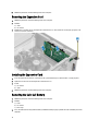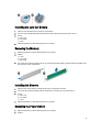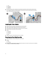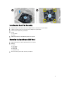
1
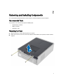
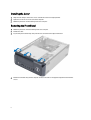
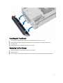
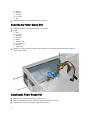
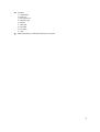
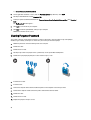
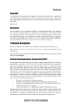
Dell Vostro 270s
Owner’s Manual
Regulatory Model: D06S
Regulatory Type: D06S001
Notes, Cautions, and Warnings
NOTE: A NOTE indicates important information that helps you make better use of your computer.
CAUTION: A CAUTION indicates either potential damage to hardware or loss of data and tells you how to avoid the
problem.
WARNING: A WARNING indicates a potential for property damage, personal injury, or death.
© 2012 Dell Inc.
Trademarks used in this text: Dell™, the DELL logo, Dell Precision™, Precision ON™,ExpressCharge™, Latitude™, Latitude ON™,
OptiPlex™, Vostro™, and Wi-Fi Catcher™ are trademarks of Dell Inc. Intel®, Pentium®, Xeon®, Core™, Atom™, Centrino®, and Celeron®
are registered trademarks or trademarks of Intel Corporation in the U.S. and other countries. AMD® is a registered trademark and
AMD Opteron™, AMD Phenom™, AMD Sempron™, AMD Athlon™, ATI Radeon™, and ATI FirePro™ are trademarks of Advanced Micro
Devices, Inc. Microsoft®, Windows®, MS-DOS®, Windows Vista®, the Windows Vista start button, and Office Outlook® are either
trademarks or registered trademarks of Microsoft Corporation in the United States and/or other countries. Blu-ray Disc™ is a trademark
owned by the Blu-ray Disc Association (BDA) and licensed for use on discs and players. The Bluetooth® word mark is a registered
trademark and owned by the Bluetooth® SIG, Inc. and any use of such mark by Dell Inc. is under license. Wi-Fi® is a registered
trademark of Wireless Ethernet Compatibility Alliance, Inc.
2012 - 10
Rev. A00
Contents
Notes, Cautions, and Warnings...................................................................................................2
1 Working on Your Computer.......................................................................................................5
Before Working Inside Your Computer.....................................................................................................................5
Turning Off Your Computer.......................................................................................................................................6
After Working Inside Your Computer........................................................................................................................6
2 Removing and Installing Components.....................................................................................7
Recommended Tools................................................................................................................................................7
Removing the Cover..................................................................................................................................................7
Installing the Cover...................................................................................................................................................8
Removing the Front Bezel.........................................................................................................................................8
Installing the Front Bezel..........................................................................................................................................9
Removing the Fan Shroud.........................................................................................................................................9
Installing the Fan Shroud........................................................................................................................................10
Removing the Drive Cage.......................................................................................................................................10
Installing the Drive Cage.........................................................................................................................................12
Removing the Optical Drive....................................................................................................................................12
Installing the Optical drive......................................................................................................................................12
Removing the Hard Drive........................................................................................................................................13
Installing the Hard drive..........................................................................................................................................13
Removing the Expansion Card................................................................................................................................14
Installing the Expansion Card.................................................................................................................................14
Removing the Coin-Cell Battery..............................................................................................................................14
Installing the Coin-Cell Battery...............................................................................................................................15
Removing the Memory............................................................................................................................................15
Installing the Memory.............................................................................................................................................15
Removing the Power Switch...................................................................................................................................15
Installing the Power Switch....................................................................................................................................16
Removing the Heat-Sink Assembly.........................................................................................................................16
Installing the Heat-Sink Assembly..........................................................................................................................17
Removing the Input/Output (I/O) Panel...................................................................................................................17
Installing the I/O Panel............................................................................................................................................19
Removing the Processor.........................................................................................................................................19
Installing the Processor..........................................................................................................................................20
Removing the System Board...................................................................................................................................20
System Board Components....................................................................................................................................21
Installing the System Board....................................................................................................................................21
Removing the Power-Supply Unit...........................................................................................................................22
Installing the Power-Supply Unit............................................................................................................................22
3 System Setup.............................................................................................................................25
Boot Sequence.......................................................................................................................................................25
Navigation Keys......................................................................................................................................................25
System Setup Overview..........................................................................................................................................26
Enter System Setup................................................................................................................................................26
System Setup Screens............................................................................................................................................26
System Setup Options.............................................................................................................................................27
Exit....................................................................................................................................................................29
Updating the BIOS .................................................................................................................................................29
Clearing Forgotten Password.................................................................................................................................30
Clearing CMOS.......................................................................................................................................................31
System and Setup Password..................................................................................................................................32
Assigning a System Password and Setup Password......................................................................................32
Deleting or Changing an Existing System and/or Setup Password..................................................................33
Disabling a System Password..........................................................................................................................33
4 Diagnostics.................................................................................................................................35
Enhanced Pre-Boot System Assessment (ePSA) Diagnostics...............................................................................35
5 Technical Specification...........................................................................................................37
6 Contacting Dell..........................................................................................................................41
Working on Your Computer
1
Before Working Inside Your Computer
Use the following safety guidelines to help protect your computer from potential damage and to help to ensure your
personal safety. Unless otherwise noted, each procedure included in this document assumes that the following
conditions exist:
•
You have read the safety information that shipped with your computer.
•
A component can be replaced or--if purchased separately--installed by performing the removal procedure in
reverse order.
WARNING: Before working inside your computer, read the safety information that shipped with your computer. For
additional safety best practices information, see the Regulatory Compliance Homepage at www.dell.com/
regulatory_compliance
CAUTION: Many repairs may only be done by a certified service technician. You should only perform
troubleshooting and simple repairs as authorized in your product documentation, or as directed by the online or
telephone service and support team. Damage due to servicing that is not authorized by Dell is not covered by your
warranty. Read and follow the safety instructions that came with the product.
CAUTION: To avoid electrostatic discharge, ground yourself by using a wrist grounding strap or by periodically
touching an unpainted metal surface, such as a connector on the back of the computer.
CAUTION: Handle components and cards with care. Do not touch the components or contacts on a card. Hold a
card by its edges or by its metal mounting bracket. Hold a component such as a processor by its edges, not by its
pins.
CAUTION: When you disconnect a cable, pull on its connector or on its pull-tab, not on the cable itself. Some
cables have connectors with locking tabs; if you are disconnecting this type of cable, press in on the locking tabs
before you disconnect the cable. As you pull connectors apart, keep them evenly aligned to avoid bending any
connector pins. Also, before you connect a cable, ensure that both connectors are correctly oriented and aligned.
NOTE: The color of your computer and certain components may appear differently than shown in this document.
To avoid damaging your computer, perform the following steps before you begin working inside the computer.
1.
Ensure that your work surface is flat and clean to prevent the computer cover from being scratched.
2.
Turn off your computer (see Turning Off Your Computer).
CAUTION: To disconnect a network cable, first unplug the cable from your computer and then unplug the
cable from the network device.
3.
Disconnect all network cables from the computer.
4.
Disconnect your computer and all attached devices from their electrical outlets.
5.
Press and hold the power button while the computer is unplugged to ground the system board.
6.
Remove the cover.
5
CAUTION: Before touching anything inside your computer, ground yourself by touching an unpainted metal
surface, such as the metal at the back of the computer. While you work, periodically touch an unpainted metal
surface to dissipate static electricity, which could harm internal components.
Turning Off Your Computer
CAUTION: To avoid losing data, save and close all open files and exit all open programs before you turn off your
computer.
1.
Shut down the operating system:
–
In Windows 7:
–
In Windows Vista:
Click Start
, then click Shut Down.
Click Start
, then click the arrow in the lower-right corner of the Start menu as shown below, and then
click Shut Down.
–
In Windows XP:
Click Start → Turn Off Computer → Turn Off . The computer turns off after the operating system shutdown
process is complete.
2.
Ensure that the computer and all attached devices are turned off. If your computer and attached devices did not
automatically turn off when you shut down your operating system, press and hold the power button for about 6
seconds to turn them off.
After Working Inside Your Computer
After you complete any replacement procedure, ensure you connect any external devices, cards, and cables before
turning on your computer.
1.
Replace the cover.
CAUTION: To connect a network cable, first plug the cable into the network device and then plug it into the
computer.
2.
Connect any telephone or network cables to your computer.
3.
Connect your computer and all attached devices to their electrical outlets.
4.
Turn on your computer.
5.
If required, verify that the computer works correctly by running the Dell Diagnostics.
6
Removing and Installing Components
2
This section provides detailed information on how to remove or install the components from your computer.
Recommended Tools
The procedures in this document may require the following tools:
•
Small flat-blade screwdriver
•
Phillips screwdriver
•
Small plastic scribe
Removing the Cover
1.
Follow the procedures in Before Working Inside Your Computer.
2.
Remove the screws that secure the cover to the computer to slide and lift the cover upwards to remove it from the
computer.
7
Installing the Cover
1.
Align the cover along its tabs on the chassis and slide the cover to its original position.
2.
Tighten the screws to secure the cover to the computer.
3.
Follow the procedures in After Working Inside Your Computer.
Removing the Front Bezel
1.
Follow the procedures in Before Working Inside Your Computer.
2.
Remove the cover.
3.
Pry the front panel retention clips away from the chassis located at the edge of front bezel.
4.
Rotate the front bezel away from the computer to release the hooks on the opposite edge of the bezel from the
chassis.
8
Installing the Front Bezel
1.
Insert the hooks along the bottom edge of the front bezel into the slots on the chassis front.
2.
Rotate the bezel toward the computer to engage the front-panel retention clips until they click into place.
3.
Install the cover.
4.
Follow the procedures in After Working Inside Your Computer.
Removing the Fan Shroud
1.
Follow the procedures in Before Working Inside Your Computer.
2.
Remove the cover.
3.
Press in on the fan shroud to lift and release the tabs securing the fan shroud and remove it from the computer.
9
Installing the Fan Shroud
1.
Place the fan shroud over the processor fan and heat-sink assembly.
2.
Press the fan shroud until the tabs on the fan shroud snap into place.
3.
Install the cover.
4.
Follow the procedures in After Working Inside Your Computer.
Removing the Drive Cage
1.
Follow the procedures in Before Working Inside Your Computer.
2.
Remove:
a) cover
b) fan shroud
c) front bezel
3.
10
Disconnect the power and data cables from the hard drive and the optical drive.
4.
Remove the screws that secure the drive cage and lift the drive cage to remove it from the computer.
11
Installing the Drive Cage
1.
Tighten the screws to secure the drive cage to the computer.
2.
Connect the data cable and power cable to the back of the hard drive and the optical drive.
3.
Install:
a) front bezel
b) fan shroud
c) cover
4.
Follow the procedures in After Working Inside Your Computer.
Removing the Optical Drive
1.
Follow the procedures in Before Working Inside Your Computer.
2.
Remove:
a)
b)
c)
d)
3.
cover
fan shroud
front bezel
drive cage
Remove the screws that secure the optical drive to the drive cage and slide the optical drive out of the drive cage.
Installing the Optical drive
1.
Slide the optical drive into the drive cage.
2.
Align the screw holes on the optical drive with the screw holes on the drive cage.
3.
Tighten the screws to secure the optical drive to the drive cage.
4.
Install:
12
a)
b)
c)
d)
5.
drive cage
front bezel
fan shroud
cover
Follow the procedures in After Working Inside Your Computer.
Removing the Hard Drive
1.
Follow the procedures in Before Working Inside Your Computer.
2.
Remove:
a)
b)
c)
d)
3.
cover
fan shroud
front bezel
drive cage
Remove the screws that secure the hard drive to the drive cage and slide the hard drive out of the drive cage.
Installing the Hard drive
1.
Slide the hard drive into the drive cage.
2.
Align the screw holes on the hard drive with the screw holes on the drive cage.
3.
Tighten the screws that secure the hard drive to the drive cage.
4.
Install:
a)
b)
c)
d)
drive cage
front bezel
fan shroud
cover
13
5.
Follow the procedures in After Working Inside Your Computer.
Removing the Expansion Card
1.
Follow the procedures in Before Working Inside Your Computer.
2.
Remove:
a) cover.
b) fan shroud.
3.
Remove the screw that secures the expansion card to the chassis. Press down the securing tab, grasp the card
and ease it out of its connector.
Installing the Expansion Card
1.
Insert the expansion card into it's connector on the system board and press down until it is securely in place.
2.
Tighten the screw to secure the expansion card to the chassis.
3.
Install:
a) fan shroud.
b) cover.
4.
Follow the procedures in After Working Inside Your Computer.
Removing the Coin-Cell Battery
1.
Follow the procedures in Before Working Inside Your Computer.
2.
Remove:
a) cover
b) fan shroud
c) drive cage
3.
14
Press the release latch away from the battery to allow the battery to pop-up and lift the coin-cell battery out of the
computer.
Installing the Coin-Cell Battery
1.
Place the coin-cell battery into its slot on the system board.
2.
Press the coin-cell battery downward until the release latch springs back into place and secures it.
3.
Install :
a) drive cage
b) fan shroud
c) cover
4.
Follow the procedures in After Working Inside Your Computer.
Removing the Memory
1.
Follow the procedures in Before Working Inside Your Computer.
2.
Remove:
a) cover.
b) fan shroud
c) drive cage
3.
Press down on the memory retention tabs on each side of the memory module, and lift the memory module(s) out of
the connectors on the system board.
Installing the Memory
1.
Align the notch on the memory-card with the tab on the system-board connector.
2.
Press down on the memory module until the retention tabs spring back to secure them in place.
3.
Install:
a) drive cage
b) fan shroud
c) cover.
4.
Follow the procedures in After Working Inside Your Computer.
Removing the Power Switch
1.
Follow the procedures in Before Working Inside Your Computer.
2.
Remove:
15
a)
b)
c)
d)
3.
cover
fan shroud
front bezel
drive cage
Disconnect the power-switch cable from the system board and remove the cables from their routing channels.
Press the power-switch tabs to release the power switch from the front panel and slide the power switch along
with its cable through the slot on the front panel.
Installing the Power Switch
1.
Slide the power-switch along its cable through the slot on the front panel.
2.
Align and push the power-switch tabs into the slots on the front panel.
3.
Route the power-switch cable through the routing channels on the computer.
4.
Connect the power-switch cable to the system board.
5.
Install:
a)
b)
c)
d)
6.
drive cage
front bezel
fan shroud
cover
Follow the procedures in After Working Inside Your Computer.
Removing the Heat-Sink Assembly
1.
Follow the procedures in Before Working Inside Your Computer.
2.
Remove:
a) cover
b) fan shroud
3.
16
Disconnect the fan cable from the system board. Loosen the captive screws that secure the heat-sink assembly to
the computer and remove it from the computer.
Installing the Heat-Sink Assembly
1.
Align the captive screws on the heat-sink assembly with the screw holes on the system board.
2.
Tighten the captive screws to secure heat-sink assembly to the system board.
3.
Connect the fan cable to the system board.
4.
Install:
a) fan shroud.
b) cover.
5.
Follow the procedures in After Working Inside Your Computer.
Removing the Input/Output (I/O) Panel
1.
Follow the procedures in Before Working Inside Your Computer.
2.
Remove:
a)
b)
c)
d)
e)
3.
cover
fan shroud
front bezel
drive cage
expansion card
Disconnect the I/O panel cables from the system board
17
4.
Remove the I/O panel cables from the routing channels on the chassis.
5.
Remove the screw that secures the I/O panel to the front panel and slide the I/O panel toward the side and pull it
out of the front panel.
18
Installing the I/O Panel
1.
Insert the I/O panel into the slot on the front panel.
2.
Slide the I/O panel to align it with the screw holes on the front panel.
3.
Tighten the screw to secure the I/O panel to the front panel.
4.
Route the I/O panel cables through the routing channels on the chassis.
5.
Connect the I/O panel cables to the system board.
6.
Install:
a)
b)
c)
d)
e)
7.
expansion card
drive cage
front bezel
fan shroud
cover
Follow the procedures in After Working Inside Your Computer.
Removing the Processor
1.
Follow the procedures in Before Working Inside Your Computer.
2.
Remove:
a) cover
b) fan shroud
c) heat-sink assembly
3.
Press the release lever down and then move it outward to release it from the retention hook. Lift the processor
cover and remove the processor from the socket, and place it in antistatic bag.
19
Installing the Processor
1.
Insert the processor into the processor socket. Ensure the processor is properly seated.
2.
Lower the processor cover.
3.
Press the release lever down and then move it inward to secure it with the retention hook.
4.
Install:
a) heat-sink assembly
b) fan shroud
c) cover
5.
Follow the procedures in After Working Inside Your Computer.
Removing the System Board
1.
Follow the procedures in Before Working Inside Your Computer.
2.
Remove:
a) cover
b) fan shroud
c) front bezel
d) drive cage
e) memory
f) expansion card
g) heat-sink assembly
h) processor
3.
Disconnect all the cables connected to the system board.
4.
Remove the screws that secure the system board to the chassis and lift the system board up and out of the chassis.
20
System Board Components
Figure 1. Components Of The System Board
1.
2.
3.
4.
5.
6.
7.
8.
9.
power button connector
Coin-cell battery
SATA connectors
password reset jumper
front-panel audio connector
PCI Express x16 slot
Mini-Card slot
PCIe x1 slot
4–pin CPU power connecter
10.
11.
12.
13.
14.
15.
16.
CPU Socket
processor fan connector
DDR DIMM memory slots (2)
ATX 24–pin power connector
front panel USB connector
front panel USB connector
CMOS jumper
Installing the System Board
1.
Align the system board to the port connectors on the rear of the chassis and replace the system board in the
chassis.
2.
Tighten the screws to secure the system board to the chassis.
3.
Connect the power-supply unit cables to the system board.
4.
Install the:
a) processor
b) heat-sink assembly
c) expansion card
21
d)
e)
f)
g)
h)
5.
memory
drive cage
front bezel
fan shroud
cover
Follow the procedures in After Working Inside Your Computer.
Removing the Power-Supply Unit
1.
Follow the procedures in Before Working Inside Your Computer.
2.
Remove:
a) cover
b) fan shroud
c) front bezel
d) drive cage
e) memory
f) expansion card
g) fan and heat sink
h) processor
i) system board
3.
Remove the screws that secure the power-supply unit to the chassis and slide and remove the power-supply unit
away from the computer.
Installing the Power-Supply Unit
1.
Slide the power-supply unit toward the back of the chassis.
2.
Align the screw holes on the power-supply unit with the screw holes on the chassis.
3.
Tighten the screws to secure the power-supply unit to the chassis.
22
4.
Install the:
a)
b)
c)
d)
e)
f)
g)
h)
i)
5.
system board
processor
fan and heat sink
expansion card
memory
drive cage
front bezel
fan shroud
cover
Follow the procedures in After Working Inside Your Computer.
23
24
System Setup
3
System Setup enables you to manage your computer hardware and specify BIOS‐level options. From the System Setup,
you can:
•
Change the NVRAM settings after you add or remove hardware
•
View the system hardware configuration
•
Enable or disable integrated devices
•
Set performance and power management thresholds
•
Manage your computer security
Boot Sequence
Boot Sequence allows you to bypass the System Setup‐defined boot device order and boot directly to a specific device
(for example: optical drive or hard drive). During the Power-on Self Test (POST), when the Dell logo appears, you can:
•
Access System Setup by pressing <F2> key
•
Bring up the one-time boot menu by pressing <F12> key
The one-time boot menu displays the devices that you can boot from including the diagnostic option. The boot-menu
options are:
•
Removable Drive (if available)
•
STXXXX Drive
NOTE: XXX denotes the SATA drive number.
•
Optical Drive
•
Diagnostics
NOTE: Choosing Diagnostics, will display the ePSA diagnostics screen.
The boot sequence screen also displays the option to access the System Setup screen.
Navigation Keys
The following table displays the system setup navigation keys.
NOTE: For most of the system setup options, changes that you make are recorded but do not take effect until you
restart the system.
Table 1. Navigation Keys
Keys
Navigation
Up arrow
Moves to the previous field.
Down arrow
Moves to the next field.
25
Keys
Navigation
<Enter>
Allows you to select a value in the selected field (if applicable) or follow the link in the field.
Spacebar
Expands or collapses a drop‐down list, if applicable.
<Tab>
Moves to the next focus area.
NOTE: For the standard graphics browser only.
<Esc>
Moves to the previous page till you view the main screen. Pressing <Esc> in the main screen
displays a message that prompts you to save any unsaved changes and restarts the system.
<F1>
Displays the System Setup help file.
System Setup Overview
System Setup allows you to:
•
change the system configuration information after you add, change, or remove any hardware in your computer.
•
set or change a user-selectable option such as the user password.
•
read the current amount of memory or set the type of hard drive installed.
Before you use System Setup, it is recommended that you write down the System Setup screen information for future
reference.
CAUTION: Unless you are an expert computer user, do not change the settings for this program. Certain changes
can cause your computer to work incorrectly.
Enter System Setup
1.
Turn on (or restart) your computer.
2.
When the blue DELL logo is displayed, you must watch for the F2 prompt to appear.
3.
Once the F2 prompt appears, press <F2> immediately.
NOTE: The F2 prompt indicates that the keyboard has initialized. This prompt can appear very quickly, so you
must watch for it to display, and then press <F2> . If you press <F2> before you are prompted, this keystroke
will be lost.
4.
If you wait too long and the operating system logo appears, continue to wait until you see the Microsoft Windows
desktop. Then, shut down your computer and try again.
System Setup Screens
Table 2.
Menu — Appears on top of the System Setup window. This field provides a menu to access the System Setup options.
Press < Left Arrow > and < Right Arrow > keys to navigate. As a Menu option is highlighted, the Options List lists the
options that define the hardware installed on your computer.
Options List — Appears on the left
side of the System Setup window. The
field lists features that define the
configuration of your computer,
including installed hardware, power
26
Options Field — Appears on the right
side of Dell Diagnostics and contains
information about each option listed in
theDell Diagnostics. In this field you
can view information about your
Dell Diagnostics — Appears on the
right side of the System Setup window
and contains help information about
the option selected in Dell
Diagnostics.
conservation, and security features.
Scroll up and down the list with the
up- and down-arrow keys. As an
option is highlighted, the Options Field
displays the option's current and
available settings.
computer and make changes to your
current settings. Press < Enter> to
make changes to your current
settings. Press <ESC> to return to the
Dell Diagnostics.
NOTE: Not all settings listed in the
Options Field are changeable.
Function Keys — Appears below the Dell Diagnostics and lists keys and their functions within the active system setup
field.
Use the following keys to navigate through the System Setup screens:
Table 3.
Keystroke
Action
< F2 >
Displays information on any selected item in the System
Setup.
< Esc >
Exit from current view or switch the current view to the
Dell Diagnostics page in the System Setup.
< Up Arrow > or < Down Arrow >
Select an item to display.
< Left Arrow > or < Right Arrow >
Select a menu to display.
– or +
< Enter >
Change existing item value.
Select the sub menu or execute command.
< F9 >
Load setup default.
< F10 >
Save current configuration and exit System Setup.
System Setup Options
Table 4. Main
System Information
Displays the computer model number.
BIOS Version
Displays the BIOS revision.
Build Date
Displays the date the system BIOS was built.
System Date
Re-sets the date on the computer's internal calendar.
System Time
Re-sets the time on the computer's internal clock.
Service Tag
Displays the service tag of your computer.
Asset Tag
Displays the asset tag of your computer (if available).
Processor Information
Processor Type
Displays the type of processor.
L2 Cache Size
Displays the processor L2 cache size.
L3 Cache Size
Displays the processor L3 cache size.
27
Memory Information
Memory Installed
Displays the total computer memory.
Memory Speed
Displays the memory speed.
Memory Technology
Displays the type and technology.
Device Information
SATA 0
Displays the model number and capacity of the hard drive.
SATA 1
Displays the model number and capacity of the hard drive.
SATA 2
Displays the model number and capacity of the hard drive.
SATA 3
Displays the model number and capacity of the hard drive.
Table 5. Advanced
CPU Configuration
Hyper-threading
Enable or disable processor hyperthreading.
Default: Enabled
Limit CPUID Value
Enable or disable the Limit CPUID
Value feature.
Default: Enabled
CPU XD Support
Enable or disable the CPU XD feature. Default: Enabled
Intel Virtualization Technology
Enable or disable the Intel
Virtualization feature.
Default: Enabled
Intel SpeedStep
Enable or disable the Intel SpeedStep
feature.
Default: Enabled
CPU C6 Report
Enable or disable the processor
power saving report to the operating
system.
Default: Enabled
Onboard Audio Controller
Enable or disable the onboard audio
controller.
Default: Enabled
Onboard LAN Controller
Enable or disable the onboard LAN
controller.
Default: Enabled
Onboard LAN Boot ROM
Enable or disable the onboard LAN
boot ROM.
Default: Disabled
USB Controller
Enable or disable the USB controller.
Default: Enabled
USB Storage Boot Function
Enable or disable the option to boot
through a USB device
Default: Enabled
Restore AC Power Loss
Specifies how the computer will
behave when AC power is restored
after an AC power loss.
Default: Power Off
Wake on Lan from S4/S5
Allows the computer to be remotely
turned on.
Default: Enabled
System Configuration
Power Management
28
CPU Configuration
Auto Power On
Enable or disable the computer to
power on automatically. You can
further specify the date and time the
computer power on.
Default: Disabled
NumLock Key
Enable or disable the NumLock State
light during POST.
Default: On
Keyboard Error Report
Enable or disable the Keyboard Error
Report to be displayed during POST.
Default: Enabled
Post Behaviour
Table 6. Boot
Set Boot Priority
Specifies the order of different devices in which the
computer will boot through at start up.
Hard Disk Drives
Specify which hard drive the computer can boot through.
CD/DVD ROM Drives
Specify which CD/DVD the computer can boot through.
Table 7. Security
Unlock Setup Status
Specifies whether the BIOS can be edited.
Admin Password Status
Specifies whether an administrator password has been
assigned.
System Password Status
Specifies whether a system password has been assigned.
Admin Password
Allows you to change or delete the administrator
password.
Exit
This section allows you to save, discard, and load default settings before exiting from System Setup.
Updating the BIOS
It is recommended to update your BIOS (system setup), on replacing the system board or if an update is available. For
notebooks, ensure that your computer battery is fully charged and connected to a power outlet
1.
Restart the computer.
2.
Go to support.dell.com/support/downloads.
3.
If you have your computer's Service Tag or Express Service Code:
NOTE: For desktops, the service tag label is available on the front of your computer.
NOTE: For notebooks, the service tag label is available on the bottom of your computer.
a) Enter the Service Tag or Express Service Code and click Submit.
b) Click Submit and proceed to step 5.
4.
If you do not have your computer's service tag or express service code, select one of the following:
a) Automatically detect my Service Tag for me
b) Choose from My Products and Services List
29
c) Choose from a list of all Dell products
5.
On the application and drivers screen, under the Operating System drop-down list, select BIOS.
6.
Identify the latest BIOS file and click Download File.
7.
Select your preferred download method in the Please select your download method below window; click Download
Now.
The File Download window appears.
8.
Click Save to save the file on your computer.
9.
Click Run to install the updated BIOS settings on your computer.
Follow the instructions on the screen.
Clearing Forgotten Password
The system's software security features include a system password and a setup password. The password jumper
disables any password(s) currently in use. There are 3–pins for the password reset jumper.
1.
Follow the procedures in Before Working Inside Your Computer.
2.
Remove the cover.
3.
Remove the fan shroud.
4.
Identify the password reset jumper on the system board, see the System Board Components.
5.
Remove the 2-pin jumper plug from pins 2 and 3 and fix it on pins 1 and 2
6.
Install the fan shroud.
7.
Install the cover.
8.
Connect the computer to the electrical outlet and power-on the computer to clear the password.
9.
Power-off the computer and disconnect the power cable from the electrical outlet.
10. Remove the cover.
11. Remove the fan shroud.
12. Replace the jumper on the pins 2 and 3.
30
13. Install the fan shroud.
14. Install the cover.
15. Follow the procedures in After Working Inside Your Computer.
16. Power-on the computer.
17. Go to the system setup, and assign a new system or setup password.
Clearing CMOS
1.
Follow the procedures in Before Working Inside Your Computer.
2.
Remove the cover.
3.
Remove the fan shroud.
4.
Remove the front bezel.
5.
Remove the drive cage.
6.
Identify the CMOS jumper on the system board, see the System Board Components.
7.
Remove the 2-pin jumper plug from pins 2 and 3 and fix it on pins 1 and 2
8.
Install the drive cage.
9.
Install the front bezel.
10. Install the fan shroud.
11. Install the cover.
12. Connect the computer to the electrical outlet and power-on the computer to clear the CMOS.
13. Power-off the computer and disconnect the power cable from the electrical outlet.
14. Remove the cover.
31
15. Remove the fan shroud.
16. Remove the front bezel.
17. Remove the drive cage.
18. Replace the jumper on the pins 2 and 3.
19. Install the drive cage.
20. Install the front bezel.
21. Install the fan shroud.
22. Install the cover.
23. Follow the procedures in After Working Inside Your Computer.
24. Power-on the computer.
System and Setup Password
You can create a system password and a setup password to secure your computer.
Password Type
Description
System password
Password that you must enter to log on to your system.
Setup password
Password that you must enter to access and make changes to the BIOS settings of your
computer.
CAUTION: The password features provide a basic level of security for the data on your computer.
CAUTION: Anyone can access the data stored on your computer if is not locked and left unattended.
NOTE: Your computer is shipped with the system and setup password feature disabled.
Assigning a System Password and Setup Password
You can assign a new System Password and/or Setup Password or change an existing System Password and/or Setup
Password only when Password Status is Unlocked. If the Password Status is Locked, you cannot change the System
Password.
NOTE: If the password jumper is disabled, the existing System Password and Setup Password is deleted and you
need not provide the system password to log on to the computer.
To enter a system setup, press <F2> immediately after a power-on or reboot.
32
1.
In the System BIOS or System Setup screen, select System Security and press <Enter>.
The System Security screen appears.
2.
In the System Security screen, verify that Password Status is Unlocked.
3.
Select System Password , enter your system password, and press <Enter> or <Tab>.
Use the following guidelines to assign the system password:
–
A password can have up to 32 characters.
–
The password can contain the numbers 0 through 9.
–
Only lower case letters are valid, upper case letters are not allowed.
–
Only the following special characters are allowed: space, (”), (+), (,), (-), (.), (/), (;), ([), (\), (]), (`).
Re-enter the system password when prompted.
4.
Type the system password that you entered earlier and click OK.
5.
Select Setup Password, type your system password and press <Enter> or <Tab>.
6.
Type the setup password that you entered earlier and click OK.
7.
Press <Esc> and a message prompts you to save the changes.
8.
Press <Y> to save the changes.
A message prompts you to re-type the setup password.
The computer reboots.
Deleting or Changing an Existing System and/or Setup Password
Ensure that the Password Status is Unlocked (in the System Setup) before attempting to delete or change the existing
System and/or Setup password. You cannot delete or change an existing System or Setup password, if the Password
Status is Locked.
To enter the System Setup, press <F2> immediately after a power-on or reboot.
1.
In the System BIOS or System Setup screen, select System Security and press <Enter>.
The System Security screen is displayed.
2.
In the System Security screen, verify that Password Status is Unlocked.
3.
Select System Password, alter or delete the existing system password and press <Enter> or <Tab>.
4.
Select Setup Password, alter or delete the existing setup password and press <Enter> or <Tab>.
NOTE: If you change the System and/or Setup password, re-enter the new password when promoted. If you
delete the System and/or Setup password, confirm the deletion when promoted.
5.
Press <Esc> and a message prompts you to save the changes.
6.
Press <Y> to save the changes and exit from the System Setup.
The computer reboots.
Disabling a System Password
The system's software security features include a system password and a setup password. The password jumper
disables any password(s) currently in use.
NOTE: You can also use the following steps to disable a forgotten password.
1.
Follow the procedures in Before Working on Your Computer.
2.
Remove the cover.
33
3.
Identify the PSWD jumper on the system board.
4.
Remove the PSWD jumper from the system board.
NOTE: The existing passwords are not disabled (erased) until the computer boots without the jumper.
5.
Install the cover.
NOTE: If you assign a new system and/or setup password with the PSWD jumper installed, the system
disables the new password(s) the next time it boots.
6.
Connect the computer to the electrical outlet and power-on the computer.
7.
Power-off the computer and disconnect the power cable from the electrical outlet.
8.
Remove the cover.
9.
Replace the PSWD jumper on the system board.
10. Install the cover.
11. Follow the procedures in After Working on Your Computer.
12. Power-on the computer.
13. Go to the system setup, and assign a new system or setup password. See Setting up a System Password.
34
Diagnostics
4
If you experience a problem with your computer, run the ePSA diagnostics before contacting Dell for technical
assistance. The purpose of running diagnostics is to test your computer's hardware without requiring additional
equipment or risking data loss. If you are unable to fix the problem yourself, service and support personnel can use the
diagnostics results to help you solve the problem.
Enhanced Pre-Boot System Assessment (ePSA) Diagnostics
The ePSA diagnostics (also known as system diagnostics) performs a complete check of your hardware. The ePSA is
embedded with the BIOS and is launched by the BIOS internally. The embedded system diagnostics provides a set of
options for particular devices or device groups allowing you to:
•
Run tests automatically or in an interactive mode
•
Repeat tests
•
Display or save test results
•
Run thorough tests to introduce additional test options to provide extra information about the failed device(s)
•
View status messages that inform you if tests are completed successfully
•
View error messages that inform you of problems encountered during testing
CAUTION: Use the system diagnostics to test only your computer. Using this program with other computers may
cause invalid results or error messages.
NOTE: Some tests for specific devices require user interaction. Always ensure that you are present at the
computer terminal when the diagnostic tests are performed.
1.
Power-on the computer.
2.
As the computer boots, press the <F12> key as the Dell logo appears.
3.
On the boot menu screen, select the Diagnostics option.
The Enhanced Pre-boot System Assessment window is displayed, listing all devices detected in the computer. The
diagnostics starts running the tests on all the detected devices.
4.
If you wish to run a diagnostic test on a specific device, press <Esc> and click Yes to stop the diagnostic test.
5.
Select the device from the left pane and click Run Tests.
6.
If there are any issues, error codes are displayed.
Note the error code and contact Dell.
35
36
5
Technical Specification
NOTE: Offerings may vary by region. The following specifications are only those required by law to ship with your
computer. For more information regarding the configuration of your computer, click Start → Help and Support and
select the option to view information about your computer.
Table 8. System Information
System Information
Processor
Intel Celeron
L2 cache
256 KB
L3 cache
up to 6 MB
System chipset
Intel B75 Express Chipset
DMI speed
5 GT/s
Processor data width
64 bits
Table 9. Dimensions
Dimensions
Height
271.00 mm (10.67 inches)
Width
100.00 mm (3.94 inches)
Depth
376.20 mm (14.81 inches)
Weight
5.90 kg (13.01 lb)
Table 10. Memory
Memory
Connectors
two internally-accessible DDR3 DIMM sockets
Type
unbuffered, Non-ECC, dual‑channel DDR3
Speed
up to 1600 MHz
Capacities
2 GB, 4 GB, 8 GB, and 16 GB.
NOTE: The capacities supported by your computer may
vary depending on the configuration ordered.
Configurations supported
2 GB, 4 GB, 6 GB, and 8 GB.
Minimum memory
2 GB
Maximum memory
16 GB
37
Table 11. Video
Video
Video controller
Integrated
Intel HD Graphics
Discrete
one PCI Express x16, single-width, full length graphics card.
Video memory
Integrated
64 MB
Discrete
1 GB discrete video memory
NOTE: The available video memory will depend on the
graphics card installed on the computer.
Table 12. Ports
Ports
Back panel Ports
Network Adapter
one RJ45 port
USB
four 4-pin USB 2.0-compliant ports
two 9-pin USB 3.0-compliant ports
Audio
three audio input/output ports
one audio input/microphone port
Video
one VGA port
one HDMI port
Front Panel Ports
Audio
one audio output/headphone port
one audio input/microphone port
USB
two 9-pin USB 3.0-compliant ports
Table 13. Communications
Communications
Network adapter
10/100/1000 Mbps integrated network card
Wireless
Wi-Fi and Bluetooth wireless technology (optional)
Table 14. Audio
Audio
Type
integrated Intel High Definition Audio
Controller
Realtek ALC662VD
38
Table 15. Drives
Drives
Externally accessible
one 5.25-inch drive bays for a Blu-ray Disc combo (optional),
Blu-ray Disc Writer (optional), or DVD+/-RW
Internally accessible
one 3.5-inch drive bays for SATA hard drives
one SATA SSD drive (optional)
Table 16. Expansion Bus
Expansion Bus
PCI Express x1
Connectors
one
Connector size
36-pin
PCI Express x16
Connectors
one
Connector size
164-pin
PCI-E mini-card
Connectors
one
Connector size
52-pin
Table 17. Power
Power
Input voltage
100 VAC - 127 VAC / 200 VAC - 240 VAC
Input frequency
50/60 Hz
Rated input current
6.0 A/3.0 A
Table 18. Environmental
Environmental
Temperature:
Operating
10 °C to 35 °C (50 °F to 95 °F)
Storage
–10 °C to 45 °C (–14 °F to 113 °F)
Relative humidity:
20 % to 80 % (noncondensing)
Maximum vibration:
Operating
0.25 Grms
Non-Operating
2.20 Grms
Maximum shock:
39
Environmental
Operating
40 G for 2 ms with a change in velocity of 20 inches/s (51
cm/s)
Non-Operating
50 G for 26 ms with a change in velocity of 320 inches/s (813
cm/s)
Altitude:
Operating
–16 m to 3048 m (–50 to 10,000 ft)
NOTE: For altitudes above 2950 feet, the maximum
operating temperature is derated 1ºF/550 ft.
Storage
Airborne contaminant level
40
–15.20 m to 10,668 m (–50 ft to 35,000 ft)
G2 or lower as defined by ISA-S71.04-1985
Contacting Dell
6
NOTE: If you do not have an active Internet connection, you can find contact information on your purchase invoice,
packing slip, bill, or Dell product catalog.
Dell provides several online and telephone-based support and service options. Availability varies by country and
product, and some services may not be available in your area. To contact Dell for sales, technical support, or customer
service issues:
1.
Visit support.dell.com.
2.
Select your support category.
3.
If you are not a U.S. customer, select your country code at the bottom of the support.dell.com page, or select All to
see more choices.
4.
Select the appropriate service or support link based on your need.
41