1
Wireless Scanner
- MS840/MS084 -
User’s Manual
Version 1.1
Preface
About This Manual
This manual explains how to install, operate and maintain the MS840 Wireless Scanner.
No part of this publication may be reproduced or used in any form, or by any electrical or
mechanical means, such as photocopying, recording, or information storage and retrieval
systems, without permission in writing from the manufacturer. The material in this manual is
subject to change without notice.
© Copyright 2011 Unitech Electronics Co., Ltd. All rights reserved.
Unitech global website address: http://www.ute.com
Bluetooth is a registered trademark of Bluetooth SIG.
i
Regulatory Compliance Statements
FCC Warning Statement
This equipment has been tested and found to comply with the limits for a Class B digital device,
pursuant to part 15 of the FCC rules. These limits are designed to provide reasonable
protection against harmful interference in a residential installation. This equipment generates,
uses and can radiate radio frequency energy and, if not installed and used in accordance with
the instructions, may cause harmful interference with radio communications. However, there is
no guarantee that interference will not occur in a particular installation. If this equipment does
cause harmful interference with radio or television reception, which can be determined by
turning the equipment off and on, the user is encouraged to try to correct the interference by
one or more of the following measures:
–Reorient or relocate the receiving antenna.
–Increase the separation between the equipment and receiver.
–Connect the equipment into an outlet on a circuit different from that to which the
receiver is connected.
–Consult the dealer or an experienced radio/TV technician for help.
1. This Transmitter must not be co-located or operating in conjunction with any other antenna
or transmitter.
2. This equipment complies with FCC RF radiation exposure limits set forth for an
uncontrolled environment. To maintain compliance with FCC RF exposure requirements,
avoid direct contact to the transmitting antenna during transmitting.
3. Any changes or modifications (including the antennas) made to this device that are not
expressly approved by the manufacturer may void the user’s authority to operate the
equipment.
FCC Label Statement
This device complies with part 15 of the FCC rules. Operation is subject to the following two
conditions:
1. This device may not cause harmful interference, and
2. This device must accept any interference received, including interference that may cause
undesired operation.
RF Radiation Exposure Statement
For body contact during operation, this phone has been tested and meets FCC RF exposure
guidelines when used with an accessory that contains no metal and that positions the handset
a minimum of 1.5 cm from the body. Use of other accessories may not ensure compliance with
FCC RF exposure guidelines.
Canadian Compliance Statement
This Class B Digital apparatus meets all requirements of the Canadian Interference-Causing
Equipment Regulations.
Cet appareil numerique de la classe B respecte les exigences du Reglement sur le material
broilleur du Canada.
ii
European Conformity Statement
Declaration of Conformity with regards to the R&TTE 1999/5/EC and EMC 89/336/ EEC
directives.
RoHS Statement
This device conforms to RoHS (Reduction Of
Hazardous Substances) European Union
regulations that set maximum concentration limits
on hazardous materials used in electrical and
electronic equipment.
Taiwan NCC Warning Statement
交通部電信總局低功率電波輻射性電機管理辦法 (930322)
根據交通部低功率管理辦法規定:
第十二條
經型式認證合格之低功率射頻電機,非經許可,公司、商號或使用者均不得擅自變更
頻率、加大功率或變更原設計之特性及功能。
第十四條
低功率射頻電機之使用不得影響飛航安全及干擾合法通信;經發現有干擾現象時,應
立即停用,並改善至無干擾時方得繼續使用。前項合法通信,指依電信法規定作業之
無線電通信。
低功率射頻電機須忍受合法通信或工業、科學及醫療用電波輻射性電機設備之干擾。
減少電磁波影響,請妥適使用
Laser Information
The Unitech MS840/MS084 series is certified in the U.S. to conform to the requirements of
DHHS/CDRH 21CFR Subchapter J and to the requirements of IEC 825-1. Class II and Class 2
products are not considered to be hazardous. The MS840/MS084 series contains internally a
Visible Laser Diode (VLD) whose emissions do not exceed the maximum limits as set forth in
the above regulations. The scanner is designed so that there is no human access to harmful
laser light during normal operation, user maintenance or prescribed service operations.
The laser safety warning label required by the DHHS/IEC for the MS840/MS084 series'
optional laser scanner module is located on the memory compartment cover, on the back of the
unit.
CAUTION! Use of controls or adjustments or performance of procedures other than those
specified herein may result in hazardous laser light. Use of optical instruments with
the scanner, including binoculars, microscopes, and magnifying glasses, with will
increase eye damage. This does not include eyeglasses worn by the user.
iii
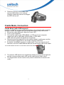
Battery Notices
The MS840 is equipped with a Lithium-Ion battery. The battery will discharge after an extended
period of no use.
When the battery is discharged, recharge the unit for some 4.5 hours in order to fully charge
the battery.
Note: To guarantee optimal performance, it is advised that rechargeable batteries be replaced
every year, or when 500 charge/discharge cycles are achieved. It is normal that the
battery balloons or expands beyond one year or the maximum of 500 cycles. Although it
does not cause harm, it cannot be used again and must be disposed of according to the
location's safe battery disposal procedures.
If the performance, of a Lithium-Ion battery, decrease is greater than 20% in, the battery
is at the end of its life cycle. Do not continue to use, and ensure the battery is disposed
of properly.
The length of time that a battery lasts depends on the battery type and how the device is used.
Conserve the battery life by doing the following:
Avoid frequent full discharges because this places additional strain on the battery. Several
partial discharges with frequent recharges are better than a full discharge. Recharging a
partially charged lithium-Ion battery does not cause harm because there is no memory
effect.
Keep the lithium-Ion battery cool. Avoid a hot car. For prolonged storage, keep the battery
at a 40% charge level.
Do not leave the lithium-Ion battery discharged and unused for an extended period
because the battery will wear out and the longevity of the battery will be at least half of the
one with frequent recharges.
Battery charge notice
It is important to consider the environment temperature when the Lithium-Ion battery pack is
charged. Charging is most efficient at normal room temperature or in a slightly cooler
environment. It is essential that batteries are charged within the stated range of 0°C to 40°C.
Charging batteries outside of the specified range could damage the batteries and shorten their
charging life cycle.
CAUTION! Do not charge batteries at a temperature lower than 0°C. This will increase the
internal resistance to cause heat and make the batteries unstable and unsafe.
Please use a battery temperature detecting device for a charger to ensure a safe
charging temperature range.
Storage and safety notice
Although the charged Lithium-Ion battery may be left unused for several months, their capacity
may be depleted due to build up of internal resistance. If this happens they will require
recharging prior to use. Lithium-Ion battery may be stored at temperatures between -30°C to
70°C, however they may deplete more rapidly at higher temperatures. It is recommended to
store batteries at room temperature.
iv
Warranty
The following items covered under the Unitech Limited Warranty are free from defects during
normal use:
MS840/MS084 – 1-year limited warranty.
Lithium-Ion battery – 6-month limited warranty.
Warranty becomes void if equipment is modified, improperly installed or used, damaged by
accident or neglect, or if any parts are improperly installed or replaced by the user.
Use only the adapter supplied. Using the wrong adapter may damage the unit and will void the
warranty.
v
vi
Table of Contents
PREFACE
ABOUT THIS MANUAL.............................................................................................................. I
Regulatory Compliance Statements.................................................................................... ii
FCC Warning Statement ......................................................................................................ii
FCC Label Statement...........................................................................................................ii
RF Radiation Exposure Statement .......................................................................................ii
Canadian Compliance Statement.........................................................................................ii
European Conformity Statement .........................................................................................iii
RoHS Statement .................................................................................................................iii
Taiwan NCC Warning Statement.........................................................................................iii
Laser Information ................................................................................................................ iii
Battery Notices .................................................................................................................... iv
Battery charge notice ..........................................................................................................iv
Storage and safety notice....................................................................................................iv
Warranty ................................................................................................................................ v
CHAPTER 1
OVERVIEW ................................................................................................................................ 1
Introducing the MS840/MS084 ............................................................................................. 1
Package Contents................................................................................................................. 2
CHAPTER 2
BATTERY CHARGING AND CONNECTION............................................................................. 5
Cradle Mode, Battery Charging ........................................................................................... 5
Cradle Mode, Connection .................................................................................................... 6
Cradle Mode (with SCM support) ........................................................................................ 6
Wall-Mount Installation of a Cradle ..................................................................................... 7
Cradle-less, Battery Charging ............................................................................................. 9
Cradle-less, Connection..................................................................................................... 10
Cradle-less Mode (without SCM support) ......................................................................... 10
Change between Cradle Mode and Cradle-less Mode..................................................... 11
Memory Buffer Setting ....................................................................................................... 12
vii
Batch Mode ....................................................................................................................... 12
Inventory Mode ................................................................................................................. 12
Connecting Multiple Scanner ............................................................................................ 13
LED / Beeper Indication for Scanner................................................................................. 14
LED Indication for Scanner ............................................................................................... 14
Beeper Indication for Scanner........................................................................................... 14
LED Indication for Cradle................................................................................................... 14
CHAPTER 3
BARCODE SETTING............................................................................................................... 15
Barcode Menu Setting........................................................................................................ 15
Barcode Length Setting ..................................................................................................... 16
Code ID Setting ................................................................................................................... 16
Preamble (Prefix) and Postamble (Suffix)......................................................................... 17
Predefined Labels............................................................................................................... 17
Quick Setup......................................................................................................................... 18
Batch Setup......................................................................................................................... 18
Scanner Configuration Manager Software ....................................................................... 20
CHAPTER 4
OUTPUT DATA EDITING......................................................................................................... 21
Programming ...................................................................................................................... 22
Programming Sequence ................................................................................................... 22
Preparation........................................................................................................................ 22
Programming Sheet .......................................................................................................... 23
Parameter Entry ................................................................................................................ 23
Qualifier ............................................................................................................................... 24
Input ID ............................................................................................................................. 24
Length ............................................................................................................................... 24
Match ................................................................................................................................ 25
Modifier................................................................................................................................ 25
A-String ............................................................................................................................. 25
O-String............................................................................................................................. 26
Examples ............................................................................................................................. 26
Example 1 ......................................................................................................................... 26
Example 2 ......................................................................................................................... 26
viii
Advanced Features............................................................................................................. 26
APPENDIX A
QUICK SETUP SHEET............................................................................................................ 29
APPENDIX B
FUNCTION CODES ................................................................................................................. 30
Function Codes for PC....................................................................................................... 30
Function Codes for IBM Terminals.................................................................................... 32
APPENDIX C
SETUP MENU.......................................................................................................................... 33
APPENDIX D
FULL ASCII CHART ................................................................................................................ 42
APPENDIX E
BARCODE TEST CHART ....................................................................................................... 46
APPENDIX F
WORLDWIDE SUPPORT ........................................................................................................ 47
ix
x
Chapter 1
Overview
Introducing the MS840/MS084
First of all, thank you for choosing Unitech’s products. This scanner has capability
of precise barcode scanning, reconnecting automatically after off-line in a long
transmitting distance. It not only provides convenient and high efficient performance
but also is well featured with wireless technology.
The cradle (optional) is provided with a charger and a wireless dongle together. The
scanner has a prolonged battery life, being thus able to work continuously for 10
hours while scanning a barcode every 3 seconds in 100 meters of long-range
communication.
You can accelerate productivity, lower cost of ownership, and even enjoy the delight
of move-around freedom. The device is the best scanning partner you can trust.
Thank you for choosing Unitech product.
Features Extremely low power consumption
Firmware upgradeable
Supports most popular barcode symbologies, including GS1-128 (EAN-128),
GS1 DataBar (RSS), etc.
Supports 2 scan profiles, Cradle Mode and Cradle-less mode
User feedback via LED indicator and beeper
Beeping tone and duration programmable for Good Read
Up to 3 scanners connected to one base
Up to 4KB of memory buffer for reading when scanner out of range
Capable of transmitting scanned data, emulating a serial cable (Cradle Mode)
or as keyboard input (Cradle-less Mode), to a laptop PC or PDA with wireless
technology
Parameters programmable, including data output format, editing format,
symbologies, etc.
Over 10 hours of operation time
Application Warehouse
Pharmacies
Logistics
Retailers
Point of sale (POS)
Inventory Management
Distribution & Transportation
1
Package Contents
Please make sure the following contents are in the MS840 package box. If
something is missing or damaged, please contact your Unitech representative.
Scanner-only package
Wireless laser scanner
Power adapter
(1010-601959G)
User's manual CD
Quickly reference guide
User's manual CD
Quickly reference guide
PS2 Cable
(1550-900041G)
(Optional)
RS232 Cable
(1550-900042G)
(Optional)
Scanner-and-cradle package
Wireless laser scanner
Cradle
(5000-900007G)
Power adapter
(1010-900008G)
USB Cable
(1550-900040G)
(Optional)
Note:
1.
The items included in the package may be different, depending on your order.
Save the box and packaging material for future use in case you need to store
or ship the scanner.
2.
When you receive and unpack the package at first time, if any item above is
lost, please contact the dealer you bought from, immediately.
3.
Environment temperature for charging should be between 0°C - 40°C.
4.
Up to 3 scanner devices work with only 1 host PC through 1 cradle or wireless
receiver.
5.
The scanner’s default power off (idle mode) time is 1 min.
6.
When you use the scanner for the first time, the scanner must be charged
continuously for some 4.5 hours.
2
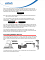
[Scanner Body Aspect]
1
2
3
4
5
6
1
LED indicator
2
Scanner Grip
3
Laser Exit Window
4
Trigger
5
Scanner Contact Points for Charge
6
Reset Pinhole
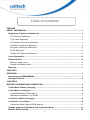
[Cradle Aspect]
7
8
4
1
9
2
10
11
5
3
12
6
13
1
Antenna
2
Communication Status LED
3
Page Button
4
Wedge Note 1
5
Power LED
6
Cradle Contact Points for
Charge
7
Cradle Foot Note 2
8
Cradle address barcode
9
Interface Switch Note 3
10
USB/RS232/PS2 Socket
11
Reset Pinhole
12
DC Power Socket (5V)
13
Guidance Groove Note 4
3
Note:
1. If you remove the wedge and flip it upside down, it acts as a clip to hold up the scanner
when the base is mounted to the wall.
2. The cradle foot serves for table mount when being fixed to the upper portion adjacent to
the antenna; the cradle foot serves for wall mount when being fixed to the lower portion
on the guidance grooves.
3. When using RS232 or PS2 cable, the interface switch should be to the left side
(default).
The USB cable can support HID (default) or COM port when switch is set to right.
Before changing the switch;
Disconnect power from cradle,
Disconnect USB cable from cradle
Set the interface switch
Connect USB Cable to cradle
Connect power to cradle
Interface switch, right
USB COM
Interface switch, left
RS232
PS2
USB HID
Operation in USB COM requires additional driver which is available at
http://www.ute.com.
In case the USB cable is been used, the cradle will receive power via USB cable. In
order to charge the scanner it is mandatory to connect power supply to cradle
4. The guidance groove is designed for arrangement of the power cord and the
communication cable (USB/RS232/PS2).
4
Chapter 2
Battery Charging and Connection
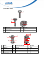
Cradle Mode, Battery Charging
The battery is in advance loaded into the compartment of the scanner and may not
be fully charged before shipment. When you receive the package and use the
MS840 for the first time, you will need to fully charge the battery.
Note: It takes approximately 4.5 hours to fully charge the battery.
To charge the scanner with a cradle, follow the instructions below:
1. Plug the adapter cable into the power
socket on the bottom of cradle.
2.
Plug the AC adapter cord into an
electrical outlet.
Now, check whether the power LED on
the cradle is bright in solid green and the
communication status LED on the cradle
is bright in solid blue.
5
3.
Place the scanner in the cradle. The
scanner LED will be red to indicate
charging. When the scanner is charged,
the LED will turn off.
Cradle Mode, Connection
Cradle Mode (with SCM support)
In order to establish a proper connection between your computer and a scanner
through a cradle, we suggest that you follow these step-by-step instructions:
1. Ensure the cradle powered, check the Power LED.
2. Turn on your computer.
3. Connect the cradle to the USB, RS232, or PS2 port of your computer
respectively with a USB cable, RS232 cable, or PS2 cable.
USB cable will operate as HID device (keyboard)
4. Determine that the power LED on the cradle is bright in solid green and the
communication status LED on the cradle is bright in solid blue.
5. By default, the MS840 operates in cradle mode. Thus, by using at most 3
scanners, scan the Cradle Address barcode on the bottom side of the cradle.
The Cradle Address barcode is on the bottom side of the cradle.
6.
7.
The scanner LED should turn off and beep shortly one time with a high tone
and the communication status LED on the cradle should flash in blue.
The Pager button can be used to verify correct connection of scanner and
cradle.
6
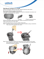
Wall-Mount Installation of a Cradle
Before mounting the cradle onto the wall, read the instruction made below.
Mounting Kit (Optional article 4070-900011G)
If you want to mount the MS840 cradle onto the wall, an iron plate, two screws, and
two plastic conical anchors are required.
Iron Plate
2 Screws
2 Plastic Conical Anchors
Before mounting the cradle onto the wall, prepare a screwdriver and read the
step-by-step instructions made below.
Follow the steps below to mount the cradle onto the wall.
Step 1: Loose and remove 2 screws from the stand of cradle by using a screwdriver.
Then, remove the stand from the cradle.
Step 2: Move the stand of cradle to the lower portion of the cradle from the upper
portion adjacent to the antenna. Then, secure the stand to the cradle with 2
screws by using the screwdriver.
7
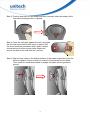
Step 3: Push up and shift out the wedge and then inversely insert the wedge. Note
that the protruding portion is upward.
Step 4: Place the iron plate against the wall, and mark
the 2 screw hole locations with a pen or pencil. Drill
the screw locations somewhat deep. Insert 2 plastic
conical anchors into the screw holes. Attach and
secure the plate to the wall with the 2 screws.
Step 5: Align the two holes on the bottom surface of the cradle respectively with the
two short pillars of the iron plate for insertion of the pillars into the holes.
Then, push the cradle downwards to wedge the pillars into the guidance
groove.
8
Step 6: The cradle wall-mount installation is completed, as shown in the figure
below.
Cradle-less, Battery Charging
To charge the scanner without a cradle, follow the instructions below:
1. Plug the adapter cable into the power
socket of the foot of scanner.
2.
Plug the AC adapter cord into an
electrical outlet.
Now, check whether the scanner LED
will be bright in solid red during
charging.
When the charging is done, the
scanner LED will turn off.
9
Cradle-less, Connection
Cradle-less Mode (without SCM support)
MS840 can connect directly to a Host with proper supported wireless technology. In
order to establish a proper connection between your Host with wireless technology
and the scanner, we suggest that you follow these step-by-step instructions:
1. Turn on your Host.
2. Change the default cradle-mode to the cradle-less mode by scanning the
Cradle-less Mode barcode.
Cradle-less Mode
3.
4.
5.
When the change is successful, the LED indicator of scanner flashes in blue.
Make your Host with wireless technology search for the MS840 scanner. When
your Host locates a “HID SCANNER”, select it.
The Host should now present a pairing pin and you will be requested to input the
pin code at the Scanner. For inputting the pin code, scan the “Link Keys” barcode
below:
Link Keys
6.
At this step, referring to the barcode table below, scan the pin code one after
another you got from your PC; for example, if you get the pin code “241657”, then
scan the barcodes “2” – “4” – “1” – “6” – “5” – “7” listed in the table in the order.
0
8
1
9
2
A
3
B
4
C
5
D
6
E
7
F
10
7.
After you finish in scanning the pin code, scan the barcode as shown below:
8.
CR($M)
When the pairing is successful, the scanner LED is off and has a short beep.
The scanner will operate as HID (keyboard) towards host.
Note: When scanning a wrong character, scan the DLE($P) to erase the
character(s). After scanning the DLE($P) barcode, please re-scan the pairing pin.
DLE($P)
Change between Cradle Mode and Cradle-less Mode
You may make the scanner change between cradle mode and cradle-less mode.
For example, if your scanner operates currently in cradle-less mode and you want
to change the existing mode of the scanner to cradle mode, then scan the Cradle
Mode barcode as shown below:
Cradle Mode
To determine whether your scanner mode is successfully changed, press the Page
button on the cradle; your scanner will have 2 short beeps when you press the
Page button.
For example, if your scanner operates currently in cradle mode and you want to
change the existing mode of the scanner to cradle-less mode, then scan the
Cradle-less Mode barcode as shown below:
Cradle-less Mode
Whenever the scanner enters cradle-less mode, you must pair the scanner with
your PC following step 3 through step 8 at the section called “Cradle-less Mode
(without SCM Support)”.
Note: When you successfully connected in Cradle and/or Crade-less, both
addresses are memorized in the scanner. To completely disconnect the
scanner;
1.Scan the Cradle Mode barcode, scan the Delete Address barcode; and
2.Scan the Cradle-less Mode barcode, scan the Delete Address barcode.
Delete
Delete
BT
Address
Address
11
Memory Buffer Setting
The collected data can be sent back to a host computer one by one via the WPAN
connection as the scanner is set to the Batch Mode, or can be stored in the flash
memory of the scanner being set to the Inventory Mode.
By default, the Batch Mode is enabled for use when the scanner is out of range.
Upon reading a barcode successfully within range, the scanner responds with one
short beep (high tone) and its LED indicator becomes solid green and goes off
quickly. However, the host computer may not receive the data immediately if
getting out of range. With the 4 KB transmit buffer, the scanner can ignore the
transmission status and keep on reading barcodes until the buffer is full.
When the Batch Mode is enabled and the scanner is out of range, the scanner will
respond with two short beeps, high-low tone, upon reading a barcode successfully.
When the memory buffer is full, the scanner will respond with one long beep (low
tone) and its LED indicator will become solid red and go off quickly. You are
advised to get back to range.
MS840 features 2 memory mode settings: Batch Mode and Inventory Mode
Note: The 4 KB of memory buffer in the scanner can hold as many as 256 scans
based on EAN-13 barcodes. Data will be cleared out once the scanner is not
powered!
Batch Mode
Batch Mode is the default setting. To set the scanner to the Batch Mode, scan the
following barcodes in the order:
E1
Enter Group 6
2
Exit
In the Batch Mode, once you scan a barcode by using a scanner wirelessly
connecting to the cradle (Cradle Mode) or a host PC (Cradle-less Mode) in a
specified range, the scanner sends out the data. When the scanner is out of range
of the cradle or the host and keeps trying to re-connect, the scanner will keep the
data in its memory buffer until the buffer is full; when the scanner is again in range
of the cradle or the host, the scanner will sent out the data that it has in the memory
buffer . When the buffer is full and the scanner is out of range, the scanner will
respond with one long beep (low tone) and its LED indicator will become solid red
and go off quickly. You are advised to get back to range.
Inventory Mode
Inventory Mode is the mode in which the scanner keeps the scanned data in its
memory buffer but not send out the data on the host automatically; you should scan
Read Buffer barcode to order the scanner sent out the memorized data to the Host.
To set the scanner to the Inventory Mode, scan the following barcodes in the order:
Enter Group 6
E1
1
12
Exit
Bear in mind the fact that the scanner operating in the inventory mode does not
send out the scanned data automatically but keeps the data in its memory buffer. If
you want to make the scanner output the data it scanned before, please scan the
Read Buffer barcode as shown below:
Read Buffer
Note: After scanning the Read Buffer barcode, the data is sent and deleted from
the scanner’s memory buffer.
If you do not output the barcode data, the barcode data is always kept in the
memory buffer. To erase the data from the scanner’s memory buffer, scan the
following barcodes in the order.
Buffer Erasable
Erase Buffer
If you are out of range of the cradle or the host PC when reading out the scanned
data, the scanner will keep the data in its memory buffer until the buffer is full; only
when the scanner is within the specified range of the cradle or the host, and you
scan the Read Buffer barcode the data will be sent.
When the buffer is disabled and the scanner is out of range, the scanner will
respond with one long beep (low tone) and its LED indicator will become solid red
and go off quickly. You are advised to get back to range.
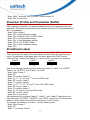
Connecting Multiple Scanner
Up to 3 scanners can be connected to 1 cradle. When data is scanned (at the same
time) the cradle will sent the data from one scanner and then the date of the other
scanner. Different Prefix/Suffix per scanner will allow which scanner has sent the
data
USB Interface
PS2 Interface
RS232 Interface
Wireless connection to cradle
If multiple scanners are connected to Host, in cradle-less mode, the data will/can
become mixed up (simultaneous scan).
13
LED / Beeper Indication for Scanner
LED Indication for Scanner
The LED lights on the MS840 scanner turn on to indicate the status of the battery, a
successful read of a barcode, or the status of the wireless connection.
MS840 Lights: The status LED turns green, blue, or red to indicate the status of the
battery and scanning.
LED Light State
What it means
Red LED flashes per 5 seconds Low battery power
1. Barcode reading when the trigger is pressed
Red LED on
2. Battery charging when the scanner is set on the cradle
Green LED flashes
Successful barcode reading
Blue LED fast blinks and then
Successful pairing/connection/reconnection (Cradle
turns off
mode)
Blue LED slow blinks
Disconnect (out of range)
Green LED blinks
Entering barcode setting mode
1. Exiting barcode setting mode
Green LED on
2. Battery charging completion
Green and blue LEDs blink
Pin code setting (waiting to enter a pin code)
Beeper Indication for Scanner
The MS840 uses beeps to give you audio feedback when it performs some
functions. For example, you hear a beep each time you scan a valid barcode.
Beep Sequence
What it means
One short beep with a Hi tone
1. Successful barcode reading
2. Pin code setting (waiting to enter a pin code)
One beep with a Hi tone
Successful pairing/connection/reconnection (Cradle
mode)
3 Hi-Low alarms
Disconnect (out of range)
One long beep with a Hi tone
Entering barcode setting mode
One short beep with a Hi-Low
Exiting barcode setting mode
tone
2 short beeps with a Hi tone
Page calling
LED Indication for Cradle
The LED lights on the MS840 cradle turn on to indicate the status of the power and
wireless connection.
LED Light State
What it means
Blue LED blink
Connection
Blue LED on
Disconnection
Green LED on
Power on
Green LED off
Power off
14
Chapter 3
Barcode Setting
The scanner interface can be configured to fit the user's specific application. All
configuration parameters are stored in a non-volatile memory, which is retained
even if power is lost.
Barcode Menu Setting
The setup menu in Appendix D contains eight groups:
* Group 1: Device selection.
* Group 2: Beep and delay.
* Group 3: Keyboard and Wand Emulation.
* Group 4: RS-232 Settings
* Group 5: Scanner port.
* Group 6: Magnetic Reader
* Group 7: Code 39, I 2 of 5, S 2 of 5 and Code 32.
* Group 8: Code 128, Code 93, Code 11, Codabar, and MSI.
* Group 9: UPC/EAN, and Delta Distance Code.
* Group 10: Data Editing.
* Group 11: Dump setup.
Setup Procedures
For most parameters, proceed the following steps for the setting:
1. Locate a group that contains the parameter to be changed.
2.
Scan the "Enter Group #" label to enter setup mode. The green LED on the
scanner will flash to indicate that setup is in progress.
3.
Scan the label (on right hand side) representing the parameter to be changed,
such as B1 label.
4.
Scan the labels (number) representing the desired parameter value; for
example, for 05, scan “0” and “5” labels.
5.
Repeat steps 3 and 4, if necessary, to change the parameters in the same
group.
6.
Scan "Exit" label to end the group setup. The scanner will make two beeps to
end the setup.
15
Barcode Length Setting
The following example illustrates how to set Code 39 with a minimum length of 5
and a maximum length of 20.
* Scan “Enter Group 7”.
* Scan “F1” to select Code 39.
* Scan “MIN LENGTH” to enter minimum length setting.
* Scan “0” and “5” to select length 5.
* Scan “MIN LENGTH” to end minimum length setting.
* Scan “MAX LENGTH” to enter maximum length setting.
* Scan “2” and “0” to select length 20.
* Scan “MAX LENGTH” to end maximum length setting.
* Scan “Exit” to end setup.
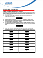
Code ID Setting
Each barcode symbology supported by the scanner has a default ID character
defined below. If you don’t know what the label that you’re scanning is, you may
use this feature to identify.
Symbology
Pre-Defined
UPC-A
A
UPC-E
E
EAN-13
F
EAN-8
FF
I 2 of 5
I
S 2 of 5
H
Code 39
M
Codabar
N
Code 93
L
Code 128
K
UCC/EAN128
]C1
MSI
O
Code 32
T
Delta Code
D
Plessey Code
P
Label Code IV,V
B
China Postal Code
C
Those ID characters can be redefined through setup menu. The following example
shows how to set Code 93 with ID ‘O’ and Code 128 without ID:
* Scan “Enter Group 5”.
* Scan “D2” to select Code ID.
* Scan “1” for "Enable".
* Scan “D3” to define IDs.
* Scan “0” and “9” for selecting Code 93.
* Scan “O” from Full ASCII Table for new ID.
* Scan “0” and "8" to select Code 128.
16
* Scan “NULL” character from Full ASCII Table for none ID.
* Scan “Exit” to end setup.
Preamble (Prefix) and Postamble (Suffix)
Regarding Preamble, the scanner adds the start of text characters before the input
data; regarding Postamble, the scanner adds the end of text characters after the
input data. The following description is an example that sets ‘STX’ as preamble and
‘ETX’ as postamble.
* Scan “Enter Group 5”.
* Scan “PP” to start preamble setting.
* Scan ‘STX’ character from Full ASCII Table.
* Scan “PP” to end preamble setting.
* Scan “OO” to start postamble setting.
* Scan ‘ETX’ from Full ASCII Table.
* Scan “OO” to end postamble setting.
* Scan “Exit”.
Predefined Labels
The scanner provides three special labels encoded as “/FY”, “/FZ”, and “/F-” in
Code 39 format. The output from these labels can be defined through the setup
menu. The definition of the labels share the same space with “Edit Formula
definition”(See “Output Data Editing”), so you can only use one of the functions.
Label 0
Label 1
Label 2
/ FY
/ FZ
/ F-
Here is an example indicating how to define the output of “Label 0” as “START”,
“Label 1” as “ACCEPT”, and “Label 2” as “END”.
* Scan “Enter Group 3”
* Scan “B7”
* Scan “0” to define “Label 0”
* Scan “S”, “T”, “A”, “R” and “T” from Full ASCII chart
* Scan “B7” to end “Label 0”
* Scan “1” to define “Label 1”
* Scan “A”, “C”, “C”, “E”, “P” and “T” from FULL ASCII chart
* Scan “B7” to end “Label 1”
* Scan “2” to define “Label 2”
* Scan “E”, “N” and “D” from Full ASCII chart
* Scan “B7” to end “Label 2”
* Scan “Exit” to quit setup
After programming, scanning “Label 0”, “Label 1”, and “Label 2” listed above will
have the output of “START”, “ACCEPT”, and “END”, respectively. The characters
defined in these labels can be ASCII characters or Function keys.
To eliminate the definition of “Label 1”, do the following scan:
* Scan “Enter Group 3”
* Scan “B7”
* Scan “1” to choose “Label 1”
17
* Scan “B7” to end
* Scan “Exit” to exit setup
There is only total 24 characters space available for defining these three labels. If
one of the labels has been defined for the output with 24 characters, the other two
labels cannot be defined further.
Quick Setup
Appendix A has a quick setup chart, which gives you one-label-for-one-function
convenience to set up the scanner. To set up the scanner, locate the label with the
function you want and scan that label.
Batch Setup
If you need to configure more than one scanner, you may duplicate the settings of
the scanner (master) to the others. You can do this by producing a set of custom
setup labels derived from the master scanner, and by scanning these labels
configuring the other scanners.
The following label is called “Dump Settings” label. Before you scan the label,
please open a text editor application (such as Notepad, Word, etc.). Scan the
following label and the settings of the scanner will dump to the screen as one or
several ASCII string(s). Use a barcode printing software, select Code 39 symbology,
and use the string(s) to generate barcode labels. You use this batch setup labels to
duplicate setting to the other scanners.
Dump Settings
If you have settings as follows:
* Device Type is “Keybaordless Wedge”.
* Do not send the check digit of UPC-A and EAN-13.
* Define Preamble as “<F1>”.
* Define Postamble as “<Tab>”.
* Define Label 0 as “START”.
When dumping settings on a PC/AT, you have the following strings:
...I800C06D51DJ8
08080A0O7C005354
415254.
Print into Code 39 bar code labels:
. . . I 8 0 0 C0 6 D5 1 DJ 8
0 8 0 8 0 A0 O7 C0 0 5 3 5 4
415254.
18
By scanning the labels from top to bottom sequentially, you may duplicate the rest
of scanners with the same settings.
The following issues should be observed:
The sequence of the strings that the scanner dumped is important. You have to
print the bar code labels and scan them in the same sequence as the one that
the scanner dumped.
When you scan the batch setup labels to configure a scanner, the previous
settings on that scanner are reset to default and then replaced by the settings
contained in the batch labels.
Only the settings that are different from the default values will be dumped. So
the number of labels produced depends on how many settings being changed
compare to the factory default setting.
The settings can be dumped to a PC or terminal only if that PC or terminal
matches the type defined by Device Type of the scanner. The previous
example of “Keyboardless Wedge” as Device Type is equivalent to a PC/AT
interface, so you cannot dump that settings to a system which dose not
support a PC/AT keyboard interface.
The following label let you dump the settings to a PC/AT regardless what kind of
device has been chosen on the scanner.
Dump Settings On PC/AT
You can adjust the length of the dumped strings by combining multiple strings
into one or breaking one string into multiple strings. The following strings have
the same effect as the dumped string listed above:
...I800C06D51DJ8080
80A0O7C005354415254.
You cannot delete any character from or add any character into the strings and the
first three characters (“...”) must present in the first string.
All characters in dumped strings are in upper case. If you see lowercase
characters in dumped strings, change them to upper case.
19
Scanner Configuration Manager Software
Scanner Configuration Manager is a utility program designed for users to
configure scanner settings on a computer by using the Microsoft Windows based
operating system. Use this program to define the settings and then download the
parameters to the scanner. Download the program from our web site:
http://www.ute.com.
The SCM is for Cradle Mode only.
SCM will be future support for MS840BT
20
Chapter 4
Output Data Editing
The Output Data Editing feature was removed from this barcode setup manual. It is
implemented to the Scanner Configuration Manager Software providing a user-friendly
interface for easier operation. Please download the latest program from Unitech’s web site at
http://www.ute.com. This chapter will mainly describe the concept and feature provided by this
data output feature. The function described here also can be replaced by the “Pre-defined
Labels” function. So if data-editing function is defined, “Pre-defined Labels” will be removed.
They cannot be defined at the same time.
General
The purpose of Data Edit is allowing you to define and modify a data record that comes from
decoding of a bar code. By using combination of formulas, you can perform the following
functions on the data received by the scanner:
A. Rearrange the output sequences.
B. Delete characters from the record.
C. Insert characters to the record, including function codes.
D. Duplicate characters in the record.
E. Insert time delay in the record
Formula
Formula is a structure that tells the scanner what and how to process the original data record
to produce the desired output. The wedge allows multiple Formulas, but the number of the
Formulas can be defined depends on the memory size allocated for Data Editing.
Original Data Structure
The original data is the decoded data plus preamble and postamble. The original data structure
is as follow:
Preamble
Decoded Data
Postamble
Formula Structure
A Formula consists of two parts: Qualifier and Modifier. Qualifier is used to verify if the data
record meets the conditions specified and Modifier is processed only if all conditions in
Qualifier are met.
Execution Sequence
If several Formulas were defined, data editing will perform sequentially from the first Formula to
the last Formula. If a Formula is qualified and executed, the further formulas will be ignored. If
none of the Formulas is executed, the data record will be discarded and there will be no output
to the host.
21
Formula Structure
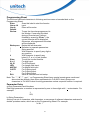
Programming
Programming Sequence
Each Formula is entered into the reader by the following sequence:
Input_ID >> Length >> Match >> A-String >> O-String >>...>> O-String >> Enter
A Formula starts with Input_ID and ends with “Enter”(a label in programming sheet). If a field is
optional and missing, the next one in the sequence can be entered. But “Enter” must be the
last input of a formula.
Preparation
To start the data editing, the following barcode sheets are needed:
-- Programming Sheet. (Setup Sheet in Appendix D).
-- Full ASCII Sheet (Appendix E).
-- Function Code Sheet (Appendix B or C).
Before programming Data Editing, you should know the format of the original data record that
may be altered by the setup groups.
22
Programming Sheet
The bold and italicized characters in following sections mean a barcode label on the
Programming Sheet.
Scan this label to start the formula
Enter
input.
Group 10
Erase all formulas.
Group
Default
To see the formulas programmed in
Review
the Wedge. If scanning this label
during a formula input (without
finished by scanning “Enter”), the
current formula will be displayed.
Otherwise, all programmed formulas
will be displayed.
Backspace Delete the last character.
Delimiter to separate parameters.
,
String specifier.
"
Wild character to specify any digit or
*
any position.
#
Wild character to specify any
letter(A--Z, a--z) or last position
To end the current formula.
Enter
0 to 9
For digit input.
For ID field input.
IN_ID
For Length field input.
LEN
For Match field input.
MATCH
For O-String input.
O-STR
For O-String input.
+
For O-String input.
Save all formulas and exit setup.
Exit
Note: The ' * ', '#' ','" ' and ', 'on Programming Sheet have special meanings as mentioned
above and are different from those represented in Full ASCII chart. Always use
characters in Full ASCII chart for string parameters unless a special function is required.
Parameter Entry
a) Digit Parameters and Numbers
Each digit parameter or number is represented by one to three digits with ‘,’ as terminator. For
example:
1,
023,
b) String Parameters
A string is a set of characters, wild characters, or sequence of adjacent characters enclosed in
double quotation marks, which are on the Programming Sheet. For example:
"A*B# "
23
Here * and # are wild characters on the setup sheet.
Qualifier
There are three conditional fields in the Qualifier:
Input ID, Length and Match.
Input ID
Format:
IN_ID,ID1, ... ,IDi,
Input ID is required and the original data record must correspond to Input ID of a formula in
order to be processed.
ID1 to IDi are represented by digits. The following Input IDs are available:
0
= Code 39 Full ASCII
1
= Code 39 Standard
2
= EAN 13
3
= EAN 8
4
= UPC A
5
= UPC E
6
= I 2 of 5
7
= Codabar
8
= Code 128
9
= Code 93
10
= S 2 of 5
11 = MSI
19 = All Inputs
There is no limitation on the number of IDs to be defined.
Example:
IN_ID,0,11,
What is shown above means the original data can be Code 39 or MSI.
Length
Format:
LEN,Min,Max,
Length field consists of two length parameters: minimum length (Min) and maximum length
(Max). When defined, a formula will be performed if the length of the original data falls between
MIN and MAX.
When missing, the following fields of current Formula are always processed.
Example:
LEN,9,48,
What is shown above means the length of original data must be within 9 and 48.
24
Match
Format:
MATCH, P0 ,"C0" ,P1, "C1" ,...,Pn, "Cn" ,
A pair of Pn and Cn forms a Match field (n indicates a sequential integer number). To define a
Match field, two parameters are required. The first is character position (Pn) and the second is
a string (Cn). Character position means the number of characters, counting from the first
character to the one to be positioned in the data record.
For example, in the following data
BARCODE
'B' has position 1.
'A' has position 2.
...
'E' has position 7.
When Match field is defined, the original data string starts at the position specified by the first
parameter P and will be compared with string "C". If the match is identical, processing of
current Formula continues.
The position parameter P could be a wild character * for any position or # for the last position
in the original data. If # is used,
#-N
is valid. Here N is a digit parameter.
The string parameter C can include * for any digit or # for any letter.
Examples:
MATCH,3,"AB",#,"?",
Checks if the original data has 'A' at position 3, 'B' at position '4' and last character is '?'.
MATCH , 10 , " *A*",
Checks if the original data includes a string with a digit as first character and "A*" followed at
position 10.
Modifier
Modifier has two types of fields: A-String and O-String to define the output contents.
A-String
Format:
"abc..."
'a', 'b' and 'c' in the string can be any character.
A-String defines a string of characters to be added to the output. For example, if the original
data is:
BCD
and output string is
BarCoDe
"ar", 'o' and 'e' in output string are added strings and can be defined by A-Strings.
Note: If '*' on Programming Sheet are included in A-String, one interblock delay defined by
Group 2 will be inserted.
25
O-String
Format:
O-STR , P, N,
O-String always applies to the original data. It contains two parameters. The first is position
parameter (P) that specifies the start output position in the original data. Parameter N tells how
many characters will be included beginning from P.
Example:
Original data is:
Barcode
Then
O-Str , 4, 4,
Gives output as
code
Note:
-- N can be '#' for all remaining characters from P.
-- If P greater than the length of original data, the O-String will be skipped.
-- If N greater than the number of remaining characters counting from P, the remaining
characters are included as valid.
Examples
Example 1
If the original data is Code 39 and content is "AA", output "ABC Company", and otherwise
output the original data as it is.
IN_ID,0,LEN,2,2,MATCH,1,"AA","ABC company",Enter
IN_ID,19,O-STR,1,#,Enter
Example 2
If the original data is Code 128 and logically divided into:
-- First six characters are personal ID,
-- Other characters are person's name.
The output will be:
-- Personal ID first,
-- A 'CR' character,
-- Two interblock delay,
-- Name,
-- A 'CR' character.
The Formula will be:
IN_ID,8,O-STR,1,6,"<CR>**",O-STR,7,#,"<CR>",Enter
<CR> is a Carriage Return character scanned from Full ASCII Chart.
Advanced Features
The O-String has the format:
O-STR,P,N,
26
Both parameters of O-String mentioned above are numbers. But both parameters can be
specified as strings. If N is a string, it becomes a position and the meaning of O-String will be
"Output from position P to position N".
If P is defined as:
"ab...ik"
a, b, I, and k can be any character, the position will be evaluated as
-- Start from the first position of the original string and search character 'a'.
-- From the position next to 'a' in original data, search for 'b'.
-- ....
-- From the position next to 'i', search for k.
-- If above searches are all found, the result of the parameter will be the position where 'k' is
located.
If N is a string, the position evaluation of N is the same as P except that the searching position
is starting from P+1.
For both P and N, if string is defined, a value can be added to or subtracted from the position.
That following O-Strings:
"ab...ik"+M,
and
"ab...ik"-M,
are meaningful. M is an integer number.
Example:
Suppose the following is a message to be modified:
%B012345678901234^ABEL/STEVE L MGR ^90010129999999?
In this message:
"%" is start sentinel.
"012345678901234" is account number.
"^" is a separator
6. "ABEL" is surname.
"/" is a separator.
"STEVE" is first name.
"L" is initial.
"MGR" is title
"^" is a separator.
"9001" is expiration date.
"?" is end sentinel.
The output sequence desired is:
Surname, First Name [CR] Account Number [CR] Expiration Date [CR]
The formula input will be:
IN_ID,0,O-STR,"^"+1,"/"-1,",",O-STR,"/"+1,"<SP>"-1,"<CR>",O-STR,3,"^"-1,"<CR>",O-STR
,"^^"+1,4,"<CR>",Enter
Here <SP> is Space character and <CR> is Carriage Return character.
27
The output of above input will be
ABEL,STEVE[CR]
012345678901234[CR]
9001[CR]
28
Appendix A
Quick Setup Sheet
Scanner Mode
Beep
UPC-A
Trigger
None
Default
Flash
Medium
Cut Leading Digit
UPC-E
Terminator
Cut Check Digit
Default
Supplement Code
Enter
No
Cut Leading Digit
Field Exit
Scan Code
Yes
Send Check Digit
Menu Setup
U.S.
UPC-A Conversion
Enable / Disable
EAN-8
Alt Key
Default
Display Version
Inter-Character Delay
Display Version
1 ms
Factory Default
Cut Leading Digit
20 ms
Cut Check Digit
Factory Default
Code ID
EAN-13
No
Default
Yes
Cut Leading Digit
Cut Check Digit
ISBN Conversion
※ In cradle mode, the cradle is set for functions
necessarily through SCM.
29
Appendix B
Function Codes
Function Codes for PC
F1 (%VA)
F2 (%VB)
F3 (%VC)
F4 (%VD)
F5 (%VE)
F6 (%VF)
F7 (%VG)
F8 (%VH)
F9 (%VI)
F10 (%VJ)
F11 (%VK)
F12 (%VL)
Cursor Right (/FC)
Cursor Left (/FD)
Cursor Up (/FE)
Cursor Down (/FF)
PgUp (/FG)
PgDn (/FH)
TAB (/FI)
Back Tab (/FJ)
Esc (/FK)
Left Enter (/FL)
Right Ctrl (/FO)
Right Enter (/FM)
Shift Make (/FP)
Ins (/FW)
Ctrl Make (/FQ)
Shift Break (/FS)
Alt Make (/FR)
Ctrl Break (/FT)
Del (/FX)
Alt Break (/FU)
30
F1 (%VA)
F13 (%VM)
Esc (/FK)
F2 (%VB)
F14 (%VN)
return (/FM)
F3 (%VC)
F15 (%VO)
Option Make (%VP)
F4 (%VD)
Cursor Left (/FD)
Option Break (%VQ)
F5 (%VE)
Cursor Right (/FC)
Control Make (%VR)
F6 (%VF)
Cursor Down (/FF)
Control Break (%VS)
F7 (%VG)
Cursor Up (/FE)
F8 (%VH)
page down (/FH)
F9 (%VI)
page up (/FG)
F10 (%VJ)
ins (/FJ)
F11 (%VK)
tab (/FI)
F12 (%VL)
Enter (/FL)
Shift Make (%VT)
Shift Break (%VU)
Apple Make (%VV)
Apple Break (%VW)
31
Function Codes for IBM Terminals
F1 (%VA)
F4 (%VD)
F3 (%VC)
F6 (%VF)
F5 (%VE)
F8 (%VH)
F7 (%VG)
F10 (%VJ)
F9 (%VI)
F12 (%VL)
F11 (%VK)
F14 (%VN)
F13 (%VM)
F16 (%VP)
F15 (%VO)
F18 (%VR)
F17 (%VQ)
F20 (%VT)
F19 (%VS)
F22 (%VV)
F21 (%VU)
F24 (%VX)
F23 (%VW)
End (/FB)
Home (/FA)
Enter (/FL)
TAB (/FI)
Field Exit (/FO)
Return (/FM)
Field - (/FQ)
Field + (/FP)
Reset (/FV)
Clear(/FR)
F2 (%VB)
32
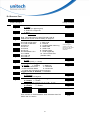
Appendix C
Setup Menu
D.1 Beeps and Delays
Enter Group 2
0
1
2
3
4
5
6
7
Group Default
Beep Tone:
0 – None
1 -- Low
2 -- Medium
3 -- High
4 -- Low to High
5 -- High to Low
Interblock Delay:
0 -- 0 ms
1 -- 10 ms
2 -- 50 ms
3 -- 100 ms
4 -- 500 ms
5 -- 1 seconds
6 -- 3 seconds
7 -- 5 seconds
Intercharacter Delay:
0 -- 0 ms
1 -- 1 ms
2 -- 2 ms
3 -- 5 ms
4 -- 10 ms
5 -- 30 ms
6 -- 50 ms
7 -- 100 ms
Power Saving Mode:
0 -- 10 minutes
1 -- 30 minutes
2 -- 60 minutes
3 -- 240 minutes
PharmaCode (Ease on decoding)
0 -- Disable
1 -- Enable
A1
A2
A3
A4
A5
Reserve
8
A6
9
Exit
33
D.2 Keyboard Wedge Settings
Enter Group 3
Group Default
Function Code:
0 -- Off
1 -- ON
B1
0
1
2
3
4
5
6
7
Caps-Lock:
0 – Auto Trace(PC/XT,AT)
1 – Lower Case
2 – Upper Case
B2
Language (For PC/XT/AT):
5-Norwegian :-Danish
0-U.S.
1-U.K.
6-Italian
;-Partial Alt
2-Swiss
7-German
<-Japanese
3-Swedish 8-French
4-Spanish 9-Alt Key Mode
B3
Output of Wand Emulation:
0—Bar with High/Space with Low
1—Bar with Low/Space with High
B4
Level Duration of Mini Width:
0—200us
1—600us
B5
Polarity of Idle Condition:
0—Low
1—High
B6
Pre-define Label:
0—Label 0
1—Label 1
2—Label 2
(See “Pre-defined label” section for detail)
Use number keypad digits:
0—Disable
1—Enable
B7
B8
8
9
Exit
34
D.3 RS232 Settings
Enter Group 4
0
1
2
3
Baud Rate:
0 -- 300
1 -- 600
2 -- 1200
3 – 2400
Parity:
0 – Even
1 – Odd
2 – Mark
Group Default
4 – 4800
5 – 9600
6 – 19200
7 – 38400
3 -- Space
4 -- None
Data Bit:
0–7
1–8
6
7
BCC Character (for serial wedge):
0 – Off
1 – On
5
8
9
C2
C3
Handshaking (for serial wedge):
0 – Ignore 1 – RTS Enabled in
Communication
2 – RTS Enable at Power up
3 / 4 – Special Bell Off / On
ACK/NAK (for serial wedge):
0 – Off
1 – On
4
C1
Time Out (for serial wedge):
0 -- 1 sec
1 – 3 sec
2 – 10sec
3 – Unlimited
C4
C5
C6
C7
Data Direction (for Terminal Wedge):
0 – Send to Host
1 – Send to Host and Terminal
2 – Send to Terminal
Define Terminator of RS232 input:
Scan an ASCII code in full ASCII Chart to
select a new RS232 Terminator.
C8
C9
Exit
35
D.4 Scanner Port
Enter Group 5
0
1
2
3
4
5
6
7
8
9
Group Default
Terminator:
0—Enter
1--Return (on digits keypad)
2--Field Exit or Right Ctrl
3--None
Code ID: 0 – disable
1 – Enable
Note: This setting doesn’t affect EAN128 Code ID.
EAN128 has its own Code ID setting on page D.7.
10 - Standard 2 of 5
Define Code ID:
11 - MSI Code
00–Code 39 Full ASCII
12 - EAN128
01–Code 39 Standard
13 - Code32 (Italian harmacy)
02–EAN-13
14 - Delta Code
03–UPC-A
15 - Label Code
04–EAN-8
16 - Plessey Code
05–UPC-E
17 - Code 11(Special)
06–Interleaved 2 of 5
18 - China Postal code
07–Codabar
(Toshiba Code)
08–Code 128
09–Code 93
Double Verification:
0 – Off
1~7 – On(Verify 1~7 times)
Scanning Mode & Trigger Function:
1– Flashing
2 –Multiscan
0 –Trigger
3–One Press One Scan
4 –Test Mode
5–Old Laser flash Mode
6 –Continuous
7–Trigger with Command control scanning
Trigger in Flash: 8 -Enabled -, 9- Disabled
Label Type:
0 – Positive
1 – Positive and Negative
Aim function for long range laser engine:
0—Disable 1—Enable
Aiming Time: 2—0.5s, 3—1s, 4—1.5s, 5—2s
Data Length (Two Digits) Send:
1—Enable
0—Disable
Preamble
Postamble
PP
OO
Scan ‘PP\OO’ for Pre\Postamble. Scan characters from Full
ASCII char or Function
36
D1
D2
D3
Scan two digits to
choose a code, and
then scan a char. From
full ASCII table to
define ID.
D4
D5
D6
D7
D8
Exit
D.5 Operating Modes
Enter Group 6
0
Group Default
Buffer Mode
0— Disabled
1— Inventory Mode
2 — Batch Mode
E1
Reserve
1
2
E2
Buffer Transmit delay
1— 100ms
0—50ms
3— 600ms 4— 1s
6— 3s
7— 5s
Reserve
2— 300ms
5— 2s
E3
3
Reserve
4
Reserve
5
Reserve
6
Reserve
7
Reserve
8
Exit
9
37
D.6 Code 39 / I 2 of 5 / S 2 of 5 / Code 32 / EAN128
Enter Group 7
0
1
2
3
4
5
6
7
8
9
Group Default
Code 39:
0/1--Disable/Enable.
2/3--Full ASCII/ Standard.
4--Check Digit (CD) Calculate & Send.
5--CD Calculate, not send.
6 --CD not Calculate.
7/8 -- Send/No Send Start/Stop
9/: -- Double labels decoding Off/On
0 - 48 -- Min length 0 / Max length 48
I 2 of 5 (ITF):
0/1--Disable/Enable
2/3--Fix Length On/Off (by first three reads)
4--Check Digit (CD) Calculate & Send
5--CD Calculate, not send.
6—CD not Calculate
7--First Digit Suppressed.
8--Last Digit Suppressed
9 -- Not Suppressed
2 - 64 -- Min length 10 / Max length 64
S 2 of 5 / China Postal Code (Toshiba Code):
0/1--Disable/Enable
2/3 -- Fix Length On/Off (by first three reads)
4--Check Digit (CD) Calculate & Send
5--CD Calculate, not send. 6--CD not Calculate
1 - 48 -- Min length 4 / Max length 48
Code 32(Italian pharmacy):
0/1 -- Disable/Enable
2/3 -- Leading Character Send / No Send
4/5 -- Tailing Character Send / No Send
Telepen:
0/1 – Disable/Enable 2/3 – Standard/Numeric Set
UCC/EAN 128:
0/1—Disable/Enable
2/3—Code ID Disable/Enable
Note: If EAN128 be disabled, the EAN128 labels will be
decoded as Code 128
Define the EAN128 Fields separator:
Scan a ASCII code in full ASCII code chart to select a
new Fields Separator
Define a separator for double labels:
Scan a ASCII code in full ASCII code chart to select a
new definition of Func1
Min Length
Max Length
F1
F2
F3
F4
F5
F6
F7
F8
Exit
MM
NN
38
D.7 Code 128 / MSI Code / Code 93 / Codabar/ Label Code
Enter Group 8
0
1
2
3
4
5
6
7
Group Default
Code 128:
0/1 -- Disable/Enable
1-64 -- Min Length 1 / Max Length 64
MSI /Plessey Code:
0/1 -- Disable/Enable
2/3 -- Check Digit Send / No Send
4 -- Check Digit Double Module 10
5 -- Check Digit Module 11 plus 10
6 -- Check Digit Single Module 10
1-16 -- Min Length 1 / Max Length 16
Code 93:
0/1 -- Disable/Enable
1-48 -- Min Length 1 / Max Length 48
Code 11: (Special)
0/1 -- Disable/Enable
2/3 -- One / Two Check Digit
4/5 -- Check Send / No Send
1-48 -- Min Length 1 / Max Length 48
Codabar:
0/1 -- Disable/Enable
2/3 -- Start & Stop Send / No Send
4 -- Check Digit Calculate & Send
5 -- Check Digit Calculate but not Send
6 -- Check Digit not Calculate
7/8 -- CLSI Format On / Off
3-48 -- Min Length 3 / Max Length 48
Label Code IV and V:
0/1 -- Disable/Enable
2/3 – Checksum send/ No send
Min Length
G1
G2
G3
G4
G5
G6
MM
8
Max Length
NN
Exit
9
39
D.8 UPC / EAN / Delta Code
Enter Group 9
0
1
2
3
4
5
6
7
8
Group Default
UPC-A:
0/1 -- Disable/Enable
2/3 -- Leading Digit Send / No Send
4/5 -- Check Digit Send / No Send
UPC-E:
0/1 -- Disable/Enable
2/3 -- Leading Digit Send / No Send
4/5 -- Check Digit Send / No Send
6/7 -- Zero Expansion On / Off
8/9 – Disable/Enable NSC=1
EAN-13:
0/1 -- Disable/Enable
2/3 -- Leading Digit Send / No Send
4/5 -- Check Digit Send / No Send
6/7 -- ISBN Enable / Disable
EAN-8:
0/1 -- Disable/Enable
2/3 -- Leading Digit Send / No Send
4/5 -- Check Digit Send / No Send
Supplement Code:
0/1 -- Two Supplement Code Off / On
2/3 -- Five Supplement Code Off / On
4 -- Transmitted if Present
5 -- Must Present.
6/7 -- Space Separator Inserted / Not Inserted
Delta Distance Code:
0/1 -- Disable/Enable
2/3 -- Check Digit Calculated / Not Calculated
4/5 -- Check Digit Send / No Send
Reserved:
H1
H2
H3
H4
H5
H6
H7
9
RSS14 Code:
0/1 RSS14 Disable / Enable
2/3 RSS Expanded Disable / Enable
4/5 RSS Limited Disable / Enable
6/7 Linkage Digit Not Send / Send
8/9 Use UCC/EAN128 ID Off/On
H8
Exit
40
D.9 Dump Setup Strings
See the section Batch Setup for how to use the labels below.
Dump Settings
Dump Settings on PC/AT
PC/AT Interface Keyboard setting
RS232 Interface Keyboard Setting
(Speed=9600,Databit=8,Parity = None, Stop=1 Flow Control = None)
41
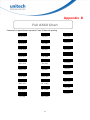
Appendix D
Full ASCII Chart
Characters in parentheses represent Code 39 barcode printing
NUL (%U)
LF ($J)
DC4 ($T)
SOH ($A)
VT ($K)
NAK ($U)
STX ($B)
FF ($L)
SYN ($V)
ETX ($C)
CR ($M)
ETB ($W)
EOT ($D)
SO ($N)
ENQ ($E)
SI ($O)
ACK ($F)
DLE ($P)
BEL ($G)
DC1 ($Q)
BS ($H)
DC2 ($R)
CAN ($X)
EM ($Y)
SUB ($Z)
ESC (%A)
FS (%B)
GS (%C)
HT ($I)
DC3 ($S)
42
RS (%D)
)
US (%E)
* (/J)
SP
+
! (/A)
, (/L)
” (/B)
-
(/I)
4
5
6
7
8
9
# (/C)
.
$
/
: (/Z)
; (%F)
%
0
< (%G)
& (/F)
1
= (%H)
’ (/G)
2
> (%I)
(
(/H)
3
43
? (%J)
J
U
@ (%V)
K
V
A
L
B
M
C
N
D
O
W
X
Y
Z
[ (%K)
E
P
F
Q
\ (%L)
] (%M)
G
R
H
S
I
T
^ (%N)
_ (%O)
44
` (%W)
k (+K)
v (+V)
a (+A)
l (+L)
w (+W)
b (+B)
m (+M)
c (+C)
n (+N)
d (+D)
o (+O)
e (+E)
p (+P)
x (+X)
y (+Y)
z (+Z)
{ (%P)
| (%Q)
f (+F)
q (+Q)
} (%R)
g (+G)
r (+R)
~ (%S)
h (+H)
s (+S)
DEL (%T)
i (+I)
t (+T)
j (+J)
u (+U)
45
Appendix E
Barcode Test Chart
EAN-13
Code 39
W+ E + D + G + E
3 045214 834123
EAN-8
Code 39 with C/D
UNI T E CH- E
8012 3453
UPC-A
0
EAN 128
47669 13716
6
(01)054123456789(01)659344
UPC-E
Code 128
99
0 123457 2
ISBN
Unitech 128
957-630-239-0
00270
Codabar
A2 2 3 5 7 0 0 0 5 9 9 8 7 6 B
9 789576 302398
Interleaved 2 of 5
MSI Code
0987654321
1234558
46
Appendix F
Worldwide Support
Unitech’s professional support team is available to quickly answer questions or
technical-related issues. Should a set of equipment problem occurs, please contact the nearest
Unitech regional service representative. For complete contact information please visit the Web
sites listed below:
Region
Web Site
Global Operation Center
http://www.ute.com
Unitech Taiwan
http://tw.ute.com
Unitech Asia Pacific & Middle East
http://apac.ute.com
http://india.ute.com
Greater China Division
http://cn.ute.com
Unitech Japan
http://jp.ute.com
Unitech America
http://us.ute.com ; http://can.ute.com
Unitech Latin America
http://latin.ute.com
Unitech Europe
http://eu.ute.com
47
;