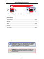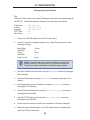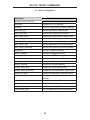
1
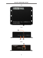
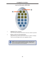
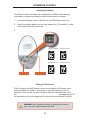
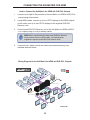
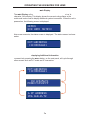
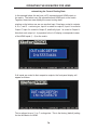
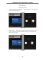
1080P 8x8 Matrix for HDMI w/4 ELR-POL Outputs GEF-HDFST-848-4ELR User Manual www.gefenpro.com ® ASKING FOR ASSISTANCE Technical Support: Telephone Fax (818) 772-9100 (800) 545-6900 (818) 772-9120 Technical Support Hours: 8:00 AM to 5:00 PM Monday thru Friday, Pacific Time Write To: Gefen, LLC. c/o Customer Service 20600 Nordhoff St Chatsworth, CA 91311 www.gefenpro.com [email protected] Notice Gefen, LLC reserves the right to make changes in the hardware, packaging, and any accompanying documentation without prior written notice. 8x8 Matrix for HDMI w/4 ELR-POL Outputs is a trademark of Gefen, LLC HDMI, the HDMI logo, and High-Definition Multimedia Interface are trademarks or registered trademarks of HDMI Licensing in the United States and other countries. © 2012 Gefen, LLC. All rights reserved. All trademarks are the property of their respective owners. Rev A1 CONTENTS 1 2 3 4 4 5 6 6 7 8 9 10 10 11 11 12 12 13 13 14 15 18 19 20 22 23 25 27 28 29 30 30 51 60 66 77 78 79 80 Introduction Operation Notes Features Matrix Layout Front Back Matrix Descriptions Front Back ELR-POL Receiver Layout ELR-POL Receiver Descriptions IR Remote Control Layout and Description Installing the Battery Setting the IR Channel Connecting the 8x8 Matrix for HDMI Wiring Diagram Operating the 8x8 Matrix for HDMI Main Display Determining the Current Routing State Routing Sources Locking / Unlocking the Front Panel Fast Switching Technology Determining the Current Switching Mode Changing the Switching Mode Setting the IR channel on the 8x8 Matrix for HDMI Routing Sources using the IR Remote Control EDID Management RS-232 Serial Control IP Configuration RS-232 / Telnet Commands IP / Telnet Configuration Routing / Naming / Presets Status Masking Firmware Update Rack Mount Safety Features Specifications Warranty INTRODUCTION Congratulations on your purchase of the GefenPRO 8x8 Matrix for HDMI w/4 ELR Outputs. Your complete satisfaction is very important to us. About Gefen We specialize in total integration for your home theater, while also focusing on going above and beyond customer expectations to ensure you get the most from your hardware. We invite you to explore our distinct product line. Please visit http://www.gefen.com for the latest offerings in High-Definition signal solutions or call us between the hours of 8:00 am and 5:00 pm Monday-Friday, Pacific Standard Time for assistance with your A/V needs. We’ll be happy to assist you. The GefenPRO 8x8 Matrix for HDMI w/4 ELR-POL Outputs The GefenPRO 8x8 Matrix with four ELR and four HDMI outputs routes up to eight Hi-Def sources at resolutions up to 1080p Full HD with Deep Color and multi-channel digital audio to any of eight HDTV displays, eliminating the need to disconnect and reconnect HDMI sources and displays. It features extension of four displays up to 330 feet (100 meters), using Gefen’s ELR (Extra Long Range) and POL (Power Over Link) technologies. ELR extension on four outputs allows installation of displays over a single CAT-5e cable. POL eliminates the need to externally power the four included ELR receivers. The GefenPRO 8x8 Matrix supports 3DTV and advanced digital audio formats such as Dolby® TrueHD and DTS-HD Master Audio™. Each source is accessible at all times from any display by using the included IR Remote Control, the RS-232 port, IP (Telnet or Web GUI), or by using the front-panel push buttons. Fast Switching Technology (FST) is a Gefen software implementation for HDMI products. FST was created to improve the lengthy HDMI authentication process, based on the HDMI and HDCP specifications. FST allows connecting/ disconnecting or turning any of the HDTV displays on or off without affecting other displays within the audio/video distribution system. How It Works Using HDMI cables, connect up to eight Hi-Def sources to the HDMI inputs on the matrix. Connect up to four HDTV displays to the HDMI outputs on the matrix and up to four HDTV displays to the supplied ELR-POL receivers. Use a single CAT-5e cable to connect each of the receivers to the matrix. An external power supply is not required because power is delivered by the matrix over the CAT-5e cables. 3D content can be displayed when connecting a 3DTV and 3D source. Connect the included AC power cord to the matrix and plug it into an available electrical outlet. Turn on the matrix by pressing the power switch. Apply power to sources and to the displays. The Hi-Def sources can now be routed to any display by using the IR remote control, RS-232 port, IP (Telnet or Web GUI), or by using the front-panel push buttons. 1 OPERATION NOTES READ THESE NOTES BEFORE INSTALLING OR OPERATING THE 8X8 MATRIX FOR HDMI W/4 ELR-POL OUTPUTS • EDID contains the A/V capabilities of a display device in regards to video resolutions and audio formats supported. This information is used by the source device to determine the format of the A/V signal on the outputs. The 8x8 Matrix for HDMI w/4 ELR-POL Outputs s incorporates advanced EDID management to ensure compatibility with all sources and display devices. See pages 36 for more details. • The GefenPRO 8x8 Matrix for HDMI w/4 ELR-POL Outputss can detect the presence of Deep Color (12-bit signal) automatically and will disable Deep Color EDID features across all other outputs iff any connected device or display is not capable of processing Deep Color. This automatic behavior ensures compatibility among all output devices in a mixed-device environment. This feature cannot be disabled. 2 FEATURES Supported HDMI Features • • • • • • • Resolutions up to 1080p Full HD HDCP compliant 12-bit Deep Color x.v. Color LPCM 7.1 audio, Dolby Digital® Plus, Dolby® TrueHD, and DTS-HD® Master Audio™ 3DTV pass-through Lip-Sync pass-through Features • Routes any eight Hi-Def sources to any eight HD displays, independently • ELR technology allows extension up to 330 feet (100 meters) • POL feature provides power to each ELR receiver • HDBaseT® technology • Gefen FST speeds up the HDCP authentication process • Fast and Slow FST Modes • Advanced EDID Management for rapid integration of sources and displays • Ability to save and recall presets • Supports DVI sources and displays • Field-upgradeable firmware via IP or RS-232 • Front Panel Switching • IR Control of the matrix via front panel sensor and from each Receiver (using EXT-RMT-EXTIRC) • Serial (RS-232) and IP Control via Web Server and Telnet • Rack mountable (2U tall, rack ears included) • Internal power supply with detachable IEC AC cord • Back panel master power switch Package Includes (1) 8x8 Matrix for HDMI w/4 ELR-POL Ouputs (1) Set of Rack Ears (Attached) (8) Extender for HDMI ELR-POL (Receiver Units) (1) IR Remote Control (1) AC Power Cord (1) Quick-Start Guide 3 1 2 3 4 6 5 7 8 MATRIX LAYOUT Front 4 9 10 11 13 12 14 15 16 17 18 19 MATRIX LAYOUT Back 5 MATRIX DESCRIPTIONS Front 1 LCD Display This is a two-line, sixteen-character display that shows status information and is also used to manage display / source routing. 2 Navigation Buttons (Input / Output) Used for routing and adjusting settings of the 8x8 Matrix for HDMI w/4 ELR-POL Outputs. See the information beginning on page 15 for details on using these buttons. 3 Menu Press this button to display routing, switching mode, and IP address information. 4 IR Sensor Receives signals from the IR Remote Control. 5 Lock Indicator This LED glows bright blue when the front panel is locked. 6 Lock Button Pressing this button temporarily locks the front panel controls. 7 Power Indicator This LED indicator will glow bright blue when the matrix is powered on. When the matrix is in standby mode, this LED indicator will glow bright red. The power switch, on the back of the matrix, must be switched to the the ON position in order for this LED indicator to function. 8 Power Button Press this button to power-on and power-off the matrix. 6 MATRIX DESCRIPTIONS Back 9 IP Control Connect an Ethernet cable to this port to control the 8x8 Matrix for HDMI w/4 ELR-POL Outputss using IP Control. See page 38 for more information on configuring the matrix for IP control. 10 RS-232 Connect an RS-232 cable from this DB-9 connector to the RS-232 control device. See page 28 for more information. 11 Grounding Screw Used to keep electrical current away from circuitry 12 IR EXT Connect an IR extender (Gefen part no. EXT-RMT-EXTIRC) to this jack 13 USB Service port for manufacturer use only. 14 HDMI Locking Connector Used to lock the HDMI cable in place. 15 HDMI Outputs (A - D) Connect up to four HDTV displays to each of these ports using HDMI cables. 16 HDMI Inputs (1 - 8) Connect a Hi-Def source to each of these ports using HDMI cables. 17 ELR-POL Outputs (E - H) Connect a CAT-5e (or better) cable from each of these jacks to the ELR-POL In jacks on the ELR-POL Receiver units. 18 Power Switch Turn the power ON or OFF using this switch. 19 110/220 AC Power Receptacle Connect the included AC power cord to this receptacle and connect the plug to an available electrical outlet. 7 ELR-POL RECEIVER LAYOUT Top Front 3 1 2 Back 4 8 ELR-POL RECEIVER DESCRIPTIONS Top / Front / Back 1 Power Indicator This LED indicator will glow bright blue when the matrix is powered and the ELR-POL Receiver unit is connected to the matrix using CAT-5e (or better) cable. 2 HDMI Out Connect an HDTV display to the HDMI Out port using an HDMI cable. 3 HDMI Locking Connector Used to lock the HDMI cable in place. 4 ELR-POL In Connect a CAT-5e (or better) cable from this jack to one of the ELR-POL jacks on the 8x8 Matrix for HDMI w/4 ELR-POL Outputs. 9 IR REMOTE CONTROL Layout and Description (RMT-848IR) 1 2 1 LED Button Press Indicator This LED will be activated momentarily each time a button is pressed. 2 Display and Source Selection Buttons These buttons are used to select which source is routed to a display. The Source and Display buttons are mapped as follows: NOTE: An Activity Indicator that flashes quickly while holding down any one of the 16 buttons indicates a low battery. Replace the IR Remote Control battery as soon as possible. 10 IR REMOTE CONTROL Installing the Battery The Remote Control unit ships with two batteries (CR2032 lithium battery). One battery is required for operation and the other battery is a spare. 1. Remove the battery cover on the back of the IR Remote Control unit. 2. Insert the included battery into the open battery slot. The positive (+) side of the battery should be facing up. 3. Replace the batteryy cover. Channel 0 (default): Remote Channel 1: ON 1 2 Remote Channel 2: ON 1 Remote Channel 3: ON Battery y slot DIP switches 1 2 2 ON 1 2 Setting the IR Channel The IR channel on the IR Remote Control must match the IR channel used by the 8x8 Matrix for HDMI. For example, if both DIP switches on the IR Remote Control unit are set to IR channel 0 (both DIP switches down), then the 8x8 Matrix for HDMII must also be set to IR channel 0. See pages 23 and 72 for information on how to change the IR channel on the 8x8 Matrix for HDMI. WARNING: Risk of explosion if battery is replaced by an incorrect type. Use only 3V lithium batteries CR-2032. 11 CONNECTING THE 8X8 MATRIX FOR HDMI How to Connect the 8x8 Matrix for HDMI w/4 ELR-POL Outputs 1. Connect up to eight Hi-Def sources to the 8x8 Matrix for HDMI w/4 ELR-POL Outputs s using HDMI cables. 2. Using HDMI cables, connect up to four HDTV displays to the HDMI outputs on the matrix, and up to four HDTV displays to the supplied ELR-POL Receiver units. 3. Connect each ELR-POL Receiver unit to the 8x8 Matrix for HDMI w/4 ELRPOL Outputs s using CAT-5e (or better) cables. NOTE: When connected to the matrix, each ELR-POL Receiver unit is powered over the CAT-5e cable. No external power supplies are required for the ELR-POL Receiver units. 4. Connect the AC power cord to the matrix and connect the plug to an available electrical outlet. Wiring Diagram for the 8x8 Matrix for HDMI w/4 ELR-POL Outputs ® De Hi- De Hi- Router rce ou fS De e urc o fS rce fS De Hi- rc ou HDMI CABLE RS-232 CABLE CAT-5 CABLE rce ou fS De Hi- e Hi- Hi- ou fS De e urc o fS rce ou fS De Hi- IR Extender e fS De Hi- rc ou 8x8 Matrix for HDMI w/ELR POL HD Display RS-232 Controller HD Display HD Display Extender for HDMI R ELR POLL HD Display HD Display HD Display HD Display HD Display GEF-HDFST-848-4ELR 12 OPERATING THE 8X8 MATRIX FOR HDMI Main Display The Main Display of the 8x8 Matrix for HDMI w/4 ELR-POL Outputss is a 16 character 2 line display. This display shows the current routing status of the matrix and is also used to display additional system information. When the unit is powered on, the following screen is displayed: After a few moments, the status screen is displayed. The status screen is shown below: Displaying Additional Information Consecutively pressing the Menu button, on the front panel, will cycle through other screens such as FST mode and IP information: 13 OPERATING THE 8X8 MATRIX FOR HDMI Determining the Current Routing State In the example below, the first row (OUT) represents each HDMI output on the matrix. The bottom row (IN) represents each HDMI input on the matrix. Together, these two rows display the current routing state. Starting on the bottom row, we can see that Input 3 has been routed to Outputs A, B, C, and D. Continuing on, Input 4 is routed to Output E, Input 6 is routed to Output F, Input 8 is routed to Output G, and finally Input 1 is routed to Output H. Note that each output (A - H) specified in the LCD display, corresponds to each of the HDMI inputs (1 - 8) on the matrix. If all inputs are routed to their respective outputs, the front-panel display will appear as follows: This is referred to as a “1-to-1” routing state. This is the factory (default) setting for the 8x8 Matrix for HDMI. 14 OPERATING THE 8X8 MATRIX FOR HDMI Routing Sources Selecting the Output 1. To select the output, press the Out - or Out + button once. The routing state for Output A will be displayed: 2. Press the Out - or Out + button to cycle through the routing state for each output. Consecutively pressing the Out + button will cycle through each output, from left to right. 15 OPERATING THE 8X8 MATRIX FOR HDMI 3. Consecutively pressing the Out - button will cycle through each output, from right to left. Changing the Source 4. Once the desired output has been selected, press the Input + or Input button. Consecutively pressing the Input + button will increment the input value by a factor of 1 (within a range of 1 - 8). For example, if Input 4 was originally routed to Output D, then pressing the Input + button will route Input 5 to Output D. Source changed from from Input p 4 to Input p 5. 16 OPERATING THE 8X8 MATRIX FOR HDMI 5. Consecutively pressing the Input - button will decrease the input value by a factor of 1 (within a range of 1 - 8). For example, if Input 3 was originally routed to Output D, pressing the Input - button will route Input 2 to Output D. Source changed from Input p 3 to Input p 2. To change the routing status of another output, press the Output + or Output - buttons to navigate to the desired output. Use the Input + or Input - buttons to change the source. 6. Press the Menu button to return to the Routing Screen. NOTE: If the Menu button is not pressed after a routing change has been made, then the 8x8 Matrix for HDMII will automatically return to the Routing Screen after about 20 seconds. 17 OPERATING THE 8X8 MATRIX FOR HDMI Locking / Unlocking the Front Panel To prevent an accidental routing change or power-down (by pressing the Power button), the front-panel buttons on the 8x8 Matrix for HDMI w/4 ELR-POL Outputs s can be locked. Locking the matrix also disables many RS-232 / Telnet commands. Press the Lock button on the front-panel: Lock LED indicator The Lock LED will glow bright orange to indicate that the front-panel buttons on the 8x8 Matrix for HDMI w/4 ELR-POL Outputss have been locked. If any buttons (other than the Lock button) are pressed while the The 8x8 Matrix for HDMII is Locked, the following message will be displayed: 1. To unlock the 8x8 Matrix for HDMI w/4 ELR-POL Outputs, press the Lock button a second time. 18 OPERATING THE 8X8 MATRIX FOR HDMI FAST SWITCHING TECHNOLOGY Fast Switching Technology Fast Switching Technology (FST) is a Gefen software implementation for HDMI products. FST was created to improve the lengthy HDMI authentication process, based on the HDMI and HDCP specifications. FST provides quicker audio/video source switching and greatly improves the overall audio/video system behavior and performance when more than one HDTV display is used in the system setup. FST allows connecting / disconnecting or turning ON / OFF of HDTV displays without having these activities affect other Hi-Def sources routed to any other HDTV display in the same system. Fast Mode: Setting the 8x8 Matrix for HDMII to Fast Mode will improve performance when connecting / disconnecting Hi-Def sources, and powering ON / OFF HDTV displays. NOTE: When switching from Slow Mode to Fast Mode, the HDTV displays connected to the Matrix will blink momentarily. Slow Mode: When set to Slow Mode, the Matrix will follow the standard authentication process, based on the HDMI and HDCP specifications. Slow Mode is recommended when the source does not support multiple devices. 19 OPERATING THE 8X8 MATRIX FOR HDMI Determining the Current Switching Mode Each HDMI input can be set to Fast Mode or Slow Mode. It is recommended that each HDMI input be set to Fast Mode for best performance. 1. Consecutively press the Menu button on the front panel until the switching modes screen is displayed. The first row (IN) represents each HDMI input on the matrix. The bottom row (MODE) represents the current switching mode of each HDMI input. Selecting the Input 2. To change the switching mode on an HDMI input, press the Output (or Output +) button once. The switching mode for Input 1 will be displayed: The letter F indicates that the HDMI input is using Fast Mode switching. If the HDMI input is set to Slow Mode switching, a letter S will be displayed under the input. 20 OPERATING THE 8X8 MATRIX FOR HDMI 3. Press the Output - or Output + button again to cycle through the routing state for each output. Consecutively pressing the Output + button will cycle through each input, from left to right, starting with Input 1: NOTE: In Routing mode, the Output + and Output - buttons cycle through each output. In Switching mode, these same buttons are used to cycle through each input. 4. Consecutively pressing the Output - button will cycle through each output, from right to left: 21 OPERATING THE 8X8 MATRIX FOR HDMI Changing the Switching Mode 5. Once the desired input has been selected, press the Input + or Input button to toggle between Fast or Slow switching mode. Switching mode changed from Fast to Slow on Input p 3. To change the switching mode of another input, press the Output + or Output - button to navigate to the desired input. Press the Input + or Input - button to toggle the switching mode between Fast (F) or Slow (S). 6. Press the Menu button to return to the Switching mode Screen. Press the Menu button a second time to return to the Routing screen. 22 OPERATING THE 8X8 MATRIX FOR HDMI Setting the IR Channel on the 8x8 Matrix for HDMI In order for the 8x8 Matrix for HDMII to communicate with the included IR Remote Control, both the matrix and the IR Remote Control must be set to the same IR channel. Follow the procedure outlined below to set the IR channel on the 8x8 Matrix for HDMI. 1. From the Routing screen, simultaneously press the Input -, Input +, and the Output - buttons to display the IR address screen. The current IR address will be displayed along with the DIP switch settings for the IR remote control: 2. Use the Input + (or Input -) button to change the IR channel. Press the Input - button to decrease the IR channel value. Press the Input + button to increase the IR channel value. IR Channel DIP switch settings g 23 OPERATING THE 8X8 MATRIX FOR HDMI 3. After setting the IR address, make sure that the DIP switches on the IR Remote Control are set according to the information in the LCD display. See page 11 for information on setting the IR channel for the IR Remote Control unit. In this case, the 8x8 Matrix for HDMII is set to IR channel 1. Therefore, DIP switch 1 on the IR Remote Control must be set to the ON position and DIP switch 2 must be set to the OFF position. 4. Press the Menu button to return to the Routing screen. 24 OPERATING THE 8X8 MATRIX FOR HDMI Routing Sources using the IR Remote Control Buttons 1 - 8 on the IR remote control correspond to each HDMI input (Input 1 - 8) on the Matrix. Buttons A - D correspond to each HDMI output (Output A - D) and buttons E-H correspond to each ELR-POL output (Output E-H). To route a source to a display, press the desired output first, then press the input. Routing Example: Route Input 4 to Output C 1. Select Output C by pressing button C on the IR Remote Control. The number 3 will appear in the upper right-hand corner of the LCD display: LED indicates a button was pressed p Output p C selected 2. Select Input 4 by pressing button 4 on the IR Remote Control. The number 4 will appear pp in the lower right-hand corner of the LCD display: Input p 4 selected 25 OPERATING THE 8X8 MATRIX FOR HDMI 3. After the input and output have been selected on the IR Remote Control, the numbers on the far right-hand of the LCD display will disappear and the new routing state will be displayed in the LCD display: Input 4 is routed to Output p C 26 EDID MANAGEMENT External EDID Management The 8x8 Matrix for HDMII features EDID Management. Before the source can send video or audio signals, the source device reads the EDID (Extended Display Identification Data) from the output devices connected to the Splitter. The EDID contains information about what type of audio/video data that the source can send to each output device. The 8x8 Matrix for HDMII routes multiple sources to multiple output devices. This involves reading EDID data from more than one device. Management of the EDID data is important to maintain compatibility between all devices. The following EDID features are copied from Output A: • Supported Resolutions • 3D Support • Audio Features Display Connections: • If a device is not connected to Output A, then no EDID changes are made, meaning that the previous EDID information will be used. This state will be in effect until a display is connected to Output A and the Matrix is power-cycled. • EDID is built from Output A to the Input. The audio block will be copied from Output A. EDID-copying is performed only when the Matrix is reset or power-cycled. 27 RS-232 SERIAL CONTROL 54321 12345 9876 6789 Only Pins 2 (RX), 3 (TX), and 5 (Ground) are used on the RS-232 serial interface RS232 Settings Bits per second ................................................................................................. 19200 Data bits .................................................................................................................... 8 Parity .................................................................................................................. None Stop bits .....................................................................................................................1 Flow Control ....................................................................................................... None NOTE: When the matrix is locked, routing and “set”-type commands will not function. The #lock_matrix command must be used before issuing any commands within this class. See page 61. IMPORTANT: When sending RS-232 commands, a carriage return and a line feed character must be included at the end of each line. Commands are nott case-sensitive. 28 IP CONFIGURATION Configuring the IP Address The 8x8 Crosspoint Matrix for HDMII supports IP-based control using Telnet. To set up Telnet control, the network settings for the matrix must be configured via RS-232. The default network settings for the matrix are as follows: IP Address: Subnet: Gateway: HTTP Port: Telnet Port: 192.168.1.72 255.255.255.0 192.168.1.254 80 23 1. Connect an RS-232 cable from the PC to the matrix. 2. Launch a terminal emulation program (e.g. HyperTerminal) and use the following settings: Baud Rate: Data Bits: Parity: Stop Bits: Flow Control: 19200 8 None 1 None NOTE: Depending upon the network, the IP address, subnet mask, gateway (router) IP, Telnet port, and HTTP port will need to be set. Consult your network administrator to obtain the proper settings. 3. Set the IP address for the matrix using the #sipadd command (see page 56 for details). 4. Set the subnet mask using the #snetmask command (see page 57 for details). 5. Set the gateway (router) IP address using the #sgateway command (see page 50 for details). 6. Set the Telnet listening port using the #set_telnet_port command (see page 46 for details). 7. Set the HTTP listening port using the #set_http_port command (see page 43 for details) 8. Power-cycle the matrix to reboot and complete all IP setting changes. 9. After the matrix has rebooted, use the IP address that was specified in step 3 to Telnet to the matrix. 29 RS-232 / TELNET COMMANDS IP / Telnet Configuration Command Description #display_telnet_welcome Set Telnet welcome message on login #ipconfig Displays all TCP/IP settings #resetip Resets IP configuration to factory settings #set_http_port Sets the Web server listening port #set_mac_addr Sets the MAC address of the Matrix #set_telnet_pass Prompts for password when using Telnet #set_telnet_port Sets the Telnet listening port #set_telnet_username Sets the user name for the login procedure #set_webui_pass Sets the password for the Web interface #set_webui_username Sets the user name for the Web interface #sgateway Sets the IP gateway address #show_gateway Displays the gateway address #show_http_port Displays the HTTP listening port #show_ip Displays the IP address of the Matrix #show_mac_addr Displays the MAC address of the Matrix #show_netmask Displays the netmask address #show_telnet_port Displays the Telnet listening port #show_telnet_username Prompts for user name when using Telnet #show_ver_data Displays the hardware / software version #show_webui_username Displays the user name for the Web interface #sipadd Sets the IP address of the matrix #snetmask Sets the IP network mask #use_telnet_pass Use password during Telnet sessions #use_webui_pass Sets the password for the Web interface 30 RS-232 / TELNET COMMANDS #display_telnet_welcome Command The #display_telnet_welcome command sets (enables/disables) the Telnet welcome message on login. Syntax y : #display_telnet_welcome param1 Parameters: param1 State [0 - 1] State Meaning 0 Do not display welcome message 1 Display welcome message Example p : #display_telnet_welcome 1 #Telnet Welcome Screen is Enable #display_telnet_welcome 0 #Telnet Welcome Screen is Disable 31 RS-232 / TELNET COMMANDS #ipconfig Command The #ipconfig command displays the current TCP/IP settings for the matrix. Syntax y : #ipconfig Parameters: None Example p : #ipconfig -------------- TCP/IP settings ------------- MAC add = 00:1C:91:01:50:07 IP add = 192.168.1.72 Net Mask = 255.255.255.0 Gateway = 192.168.2.1 Web Server Port = 80 Telnet Server Port = 23 Telnet password at login is set to ON Telnet welcome at login is set to ON 32 RS-232 / TELNET COMMANDS #resetip Command The #resetip command resets all TCP/IP settings to factory defaults. Syntax y : #resetip Parameters: None Notes: The matrix must be rebooted after executing this command. Example p : #resetip IP Configuration Was Reset To Factory Defaults. After rebooting the matrix, the IP settings will be cleared. Running the #ipconfig command will display the updated information: #ipconfig IP: 0.0.0.0 SUBNET: 0.0.0.0 GATEWAY: 0.0.0.0 33 RS-232 / TELNET COMMANDS #set_http_port Command The #set_http_port command sets the Web server listening port. The underscore characters (“_”) must be included when typing the command name. The default port setting is 80. Also see the #show_http_port on page 51. Syntax y : #set_http_port param1 Parameters: param1 Port [0 - 65535] Notes: The matrix must be rebooted after executing this command. Example p : #set_http_port 70 HTTP Communication Port 80 Is Set. 34 Please Reboot The Unit. RS-232 / TELNET COMMANDS #set_mac_addr Command The #set_mac_addr command set the MAC address of the Matrix. The underscore characters (“_”) must be included when typing the command name. The MAC address must be specified using dot-decimal notation. Syntax y : #set_mac_addr param1 Parameters: param1 MAC address Notes: The MAC address should not be changed. This command is for administrator use only. The matrix must be rebooted after executing this command. Example p : #set_mac_addr 00.12.0e.f1.7a.ea MAC ADDRESS 00.12.0e.f1.7a.ea IS SET. UNIT. 35 PLEASE REBOOT THE RS-232 / TELNET COMMANDS #set_telnet_pass Command The #set_telnet_pass command sets the Telnet password. The underscore characters (“_”) must be included when typing the command name. The maximum length of the password is 20 characters. The password is case-sensitive. The default Telnet password is Admin. Syntax y : #set_telnet_pass param1 Parameters: param1 Password Notes: The matrix must be rebooted after executing this command. Example p : #set_telnet_pass OK_Corral TELNET Interface Password Is Set. 36 RS-232 / TELNET COMMANDS #set_telnet_port Command The #set_telnet_port command sets the Telnet listening port. The underscore characters (“_”) must be included when typing the command name. The default port value is 23. Syntax y : #set_telnet_port param1 Parameters: param1 Port [0 - 65535] Notes: The matrix must be rebooted after executing this command. Example p : #set_telnet_port 20 Telnet Communication Port 23 Is Set. Unit. 37 Please Reboot The RS-232 / TELNET COMMANDS #set_telnet_username Command The #set_telnet_username command sets the Telnet user name. The underscore characters (“_”) must be included when typing the command name. The maximum length of the user name is 8 characters. The user name is case-sensitive. The default Telnet username is Admin. Syntax y : #set_telnet_username param1 Parameters: param1 User name Notes: The matrix must be rebooted after executing this command. Example p : #set_telnet_username Doc_Holiday 38 RS-232 / TELNET COMMANDS #set_webui_pass Command The #set_webui_pass command sets the password for the Web interface. The underscore characters (“_”) must be included when typing the command name. The maximum length of the password is 8 characters. Syntax y : #set_webui_pass param1 Parameters: param1 Password Notes: The matrix must be rebooted after executing this command. Example p : #set_webui_pass reindeer Web UI Password Is Set. 39 RS-232 / TELNET COMMANDS #set_webui_username Command The #set_webui_username command sets the user name for the Web interface. The underscore characters (“_”) must be included when typing the command name. The maximum length of the password is 8 characters. Syntax y : #set_webui_username param1 Parameters: param1 User name Notes: The matrix must be rebooted after executing this command. Example p : #set_webui_username holly_jolly Web UI Password Is Set. 40 RS-232 / TELNET COMMANDS #sgateway Command The #sgateway sets the IP gateway (router) address. Dot-decimal notation must be used when specifying the IP address. The default Gateway IP address is 192.168.1.254. Syntax y : #sgateway param1 Parameters: param1 IP gateway Notes: The matrix must be rebooted after executing this command. Example: p #sgateway 192.168.2.1 GateWay Address 192.168.2.1 Is Set. Please Reboot The Unit. 41 RS-232 / TELNET COMMANDS #show_gateway Command The #show_gateway command shows the current gateway address. The underscore characters (“_”) must be included when typing the command name. Syntax y : #show_gateway Parameters: None Example: p #show_gateway GATEWAY ADDRESS IS: 192.168.2.1 #show_http_port Command The #show_http_port command shows the current HTTP listening port. The underscore characters (“_”) must be included when typing the command name. Syntax y : #show_http_port Parameters: None Example: p #show_http_port HTTP COMMUNICATION PORT IS: 80 42 RS-232 / TELNET COMMANDS #show_ip Command The #show_ip command shows the current IP address of the Matrix. The underscore character (“_”) must be included when typing the command name. Syntax y : #show_ip Parameters: None Example: p #show_ip IP ADDRESS IS: 192.168.1.72 #show_mac_addr Command The #show_mac_addr command shows the MAC address of the Matrix. The underscore characters (“_”) must be included when typing the command name. Syntax y : #show_mac_addr Parameters: None Example p : #show_mac_addr MAC ADDRESS IS: 00-12-0e-f1-7a-ea 43 RS-232 / TELNET COMMANDS #show_netmask Command The #show_netmask shows the netmask address. The underscore character (“_”) must be included when typing the command name. Syntax y : #show_netmask Parameters: None Example p : #show_netmask NET MASK ADDRESS IS: 255.255.255.0 #show_telnet_port Command The #show_telnet_port command shows the current Telnet listening port. Syntax y : #show_telnet_port Parameters: None Example p : #show_telnet_port TELNET COMMUNICATION PORT IS: 23 44 RS-232 / TELNET COMMANDS #show_telnet_username Command The #show_telnet_username command returns the user name required for login. The underscore characters (“_”) must be included when typing the command name. Syntax y : #show_telnet_username Parameters: None Example p : #show_telnet_username TELNET User Name Doc_Holiday Is Set. #show_ver_data Command The #show_ver_data command displays the hardware and firmware version of the Matrix. The underscore characters (“_”) must be included when typing the command name. Syntax y : #show_ver_data Parameters: None Example p : #show_ver_data SOFTWARE AND HARDWARE VERSION: v2.0J PCB-1707*B 45 RS-232 / TELNET COMMANDS #show_webui_username Command The #show_webui_username command returns the user name required for login. The underscore characters (“_”) must be included when typing the command name. Syntax y : #show_webui_username Parameters: None Example p : #show_webui_username The User Name For The Web UI is: holly_jolly 46 RS-232 / TELNET COMMANDS #sipadd Command The #sipadd command sets the IP address of the matrix. Dot-decimal notation must be used when specifying the IP address. Syntax y : #sipadd param1 Parameters: param1 IP address Notes: The matrix must be rebooted after executing this command. Example: p #sipadd 192.168.1.72 IP Address 192.168.2.238 Is Set. Please Reboot The Unit. 47 RS-232 / TELNET COMMANDS #snetmask Command The #snetmask command sets the IP network subnet mask. Dot-decimal notation must be used when specifying the IP network mask. The default subnet mask is: 255.255.255.0 Syntax y : #snetmask param1 Parameters: param1 Subnet mask Notes: The matrix must be rebooted after executing this command. Syntax y : #snetmask 255.255.0.0 NetMask Address 255.255.255.0 Is Set. Unit. 48 Please Reboot The RS-232 / TELNET COMMANDS #use_telnet_pass Command The #use_telnet_pass command requires or disables Telnet login credentials. The default setting is disabled (param1 = 0). The underscore characters (“_”) must be included when typing the command name. Syntax y : #use_telnet_pass param1 Parameters: param1 State [0 - 1] Value Meaning 0 Disable password 1 Enable (force) password Example p : #use_telnet_pass 1 Telnet Interface Password Is Enable #use_telnet_pass 0 Telnet Interface Password Is Disable 49 RS-232 / TELNET COMMANDS #use_webui_pass Command The #use_webui_pass command requires or disables Web UI login credentials. The default setting is disabled (param1 = 0). The underscore characters (“_”) must be included when typing the command name. Syntax y : #use_webui_pass param1 Parameters: param1 State [0 - 1] Value Meaning 0 Disable password 1 Enable (force) password Examples p : #use_telnet_pass 1 Web UI Password Is Enable #use_telnet_pass 0 Web UI Password Is Disable 50 RS-232 / TELNET COMMANDS Routing / Naming / Presets Command Description #lock_matrix Locks / unlocks the Matrix #recall_preset Recalls a routing / mask preset #save_preset Saves the current routing/masking state to a preset #set_input_name Specifies a name for an input #set_output_name Specifies a name for an output #show_input_name Displays the specified input name #show_output_name Displays the specified output name #show_r Displays the current routing state of the specified output r Routes the specified inputs to the specified outputs s Routes all outputs are routed to the specified input 51 RS-232 / TELNET COMMANDS #lock_matrix Command The #lock_matrix command locks / unlocks the Matrix. When the Matrix is locked, all functions are disabled including the front panel, RS-232, and Telnet. The underscore character (“_”) must be included when typing the command name. Syntax y : #lock_matrix param1 Parameters: param1 Value [0 - 1] Value Meaning 0 Unlock Matrix 1 Lock Matrix Example: p #lock_matrix 1 MATRIX IS LOCKED #lock_matrix 0 MATRIX IS UNLOCKED 52 RS-232 / TELNET COMMANDS #recall_preset Command The #recall_preset command recalls a routing preset. Any masked outputs will also be recalled. The underscore character (“_”) must be included when typing the command name. Syntax y : #recall_preset param1 Parameters: param1 Preset [1 - 8] Example p : #recall_preset 1 RECALLED THE ROUTING STATE SAVES TO PRESET 1 #save_preset Command The #save_preset command saves the current routing state to the specified preset. Any masked outputs will also be saved as part of the current routing state. The underscore character (“_”) must be included when typing the command name. Syntax y : #save_preset param1 Parameters: param1 Preset [1 - 8] Example p : #save_preset 1 CURRENT ROUTING STATE IS SAVED TO PRESET/INPUT 1 53 RS-232 / TELNET COMMANDS #set_input_name Command The #set_input_name command provides a name to the selected input. For example, “Input 1” could be renamed as “DVD_Player”. The maximum string length for param2 2 is 15 characters. Special characters and spaces are not permitted. If needed, use the underscore character (“_”) to separate characters. The underscore character (“_”) must be included when typing the command name. Syntax y : #set_input_name param1 param2 Parameters: param1 Input param2 Name [1 - 8] Example p : #set_input_name 5 Blu_ray Blu_ray NAME IS ASSIGNED TO INPUT 5 54 RS-232 / TELNET COMMANDS #set_output_name Command The #set_output_name command provides a name to the selected output. For example, “Output 1” could be renamed as “HDDisplay”. The maximum string length for param2 2 is 15 characters. Special characters and spaces are not permitted. If needed, use the underscore character (“_”) to separate characters. The underscore character (“_”) must be included when typing the command name. Syntax y : #set_output_name param1 param2 Parameters: param1 Output param2 Name [A - H] Example p : #set_output_name C Sony_XBR7 Sony_XBR7 NAME IS ASSIGNED TO OUTPUT C 55 RS-232 / TELNET COMMANDS #show_input_name Command The #show_input_name command shows the name provided to the specified input using the #set_input_name command. The underscore character (“_”) must be included when typing the command name. Syntax y : #show_input_name param1 Parameters: param1 Input [1 - 8] Example p : #show_input_name 5 THE NAME FOR INPUT 5 IS: Blu_ray #show_output_name Command The #show_output_name command shows the name provided to the specified input using the #set_output_name command. Syntax y : #show_output_name param1 Parameters: param1 Output [A - H] Example p : #show_output_name C THE NAME FOR OUTPUT C IS: Sony_XBR 56 RS-232 / TELNET COMMANDS #show_r Command The #show_r command shows the current routing status of the specified output. The underscore character (“_”) must be included when typing the command name. Syntax y : #show_r param1 Parameters: param1 Output [A - H] Notes: If the output has been renamed using the #set_output_name command, then the name assigned to the output will be included in parentheses. Example p : #show_r c OUTPUT C(Sony_XBR) IS ROUTED TO INPUT 4 57 RS-232 / TELNET COMMANDS r Command The r command routes the specified input to the specified outputs. If param2 2 is set to 0, then the specified input is routed to all outputs. Unlike other commands, do not precede the r command with the “#’ symbol. Syntax y : r param1 param2[...param9] Parameters: param1 Input [1 - 8] param2 Outputs [A - H] Examples: p r 7 A C D F G H INPUT 7 IS SET TO OUTPUTS A, C, D, F, G, H r 2 0 INPUT 2 IS SET TO ALL OUTPUTS. 58 RS-232 / TELNET COMMANDS s Command The s command routes the specified input to all outputs. Unlike other commands, do not precede the r command with the “#’ symbol. Syntax y : s param1 Parameters: param1 Input [1 - 8] Examples: p s 2 INPUT 2 IS SET TO ALL OUTPUTS. 59 RS-232 / TELNET COMMANDS Status Command Description #help Displays all available commands #show_fw Displays the Matrix firmware version #show_hpd Displays the HPD status of the specified output #show_rsense Displays the RSENSE status of the specified output m Displays the current matrix routing status in table format n Displays the routing status for the specified output #help Command The #help command displays help on the specified command. If param1 is not specified, then the full list of commands is displayed. Syntax y : #help [param1] Parameters: param1 Command name (optional) Example: p #help #recall_preset RECALL A ROUTING STATE PRESET PARAM 1 = 1 - 8 (PRESET/INPUT) 60 RS-232 / TELNET COMMANDS #show_fw Command The #show_fw command displays the current firmware version of the Matrix. The underscore character (“_”) must be included when typing the command name. Syntax y : #show_fw Parameters: None Example: p #show_fw FIRMWARE VERSION = EXT_HDFST_848CPN v2.0J 61 RS-232 / TELNET COMMANDS #show_hdp Command The #show_hpd command displays the HPD (Hot-Plug Detect) status of the specified output. The underscore character (“_”) must be included when typing the command name. Syntax y : #show_hpd param1 Parameters: param1 Output [A - H] Notes: If the output has been renamed using the #set_output_name command, then the name assigned to the output will be included in parentheses. Examples: p #show_hpd C HPD OF OUTPUT C(Sony_XBR) IS LOW #show_hpd A HPD OF OUTPUT A IS HIGH 62 RS-232 / TELNET COMMANDS #show_rsense Command The #show_rsense command displays Rsense status of the specified output. The underscore character (“_”) must be included when typing the command name. Syntax y : #show_rsense param1 Parameters: param1 Output [A - H] Notes: If the output has been renamed using the #set_output_name command, then the name assigned to the output will be included in parentheses. Examples: p #show_rsense A RSENSE OF OUTPUT A IS LOW #show_rsense C RSENSE OF OUTPUT C(Sony_XBR) IS HIGH 63 RS-232 / TELNET COMMANDS m Command The m command displays the current matrix routing status in table format. Unlike other commands, do not precede the m command with the “#’ symbol. Syntax y : m Parameters: None Example: p m Out: A B C D E F G H In: 3 3 4 3 4 6 8 1 ALL OUTPUTS ARE UNMASKED MATRIX IS UNLOCKED 64 RS-232 / TELNET COMMANDS n Command The n command displays the current input-output routing state for the specified output. Unlike other commands, do not precede the n command with the “#’ symbol. Syntax y : n param1 Parameters: param1 Output [A - H] Notes: If param1 = 0, then the routing status for all outputs will be displayed. Examples: p n A A3 n 0 A3B3C4D3E4F6G8H1 65 RS-232 / TELNET COMMANDS Masking Command Description #activeisp Activates ISP mode for firmware updates #echo Enables / disables RS-232 feedback #fadefault Resets the matrix to factory defaults #mask Masks the specified outputs #power Powers the matrix on or off #reboot Reboots the matrix #set_ir Sets the IR channel of the matrix #show_ir Displays the current IR channel of the matrix #show_mask Displays the output masking status #show_out_colordpt Shows the highest color depth supported by the display based on the EDID #show_out_res Shows the highest resolution supported by the display based on the EDID #unmask Unmasks the selected outputs #activeisp Command The #activeisp command activates ISP mode for upgrading the firmware. Syntax y : #activeisp Parameters: None Example p : #activeisp 66 RS-232 / TELNET COMMANDS #echo Command The #echo command enables / disables serial port (terminal) echo. Syntax y : #echo Parameters: param1 Value [0 - 1] Value Meaning 0 Disable feedback 1 Enable feedback Examples p : #echo 1 LOCAL ECHO IS ON #echo 0 LOCAL ECHO IS OFF 67 RS-232 / TELNET COMMANDS #fadefault Command The #fadefault command disables the EDID lock state, sets the default routing state (1-1, 2-2, 3-3, etc.), resets the input and output names to the default names (e.g. Output 1, Input 1), and resets the IP configuration to the default settings. Syntax y : #fadefault Parameters: None Syntax y : #fadefault MATRIX WAS RESET TO FACTORY DEFAULTS INPUT 1 IS ROUTED TO OUTPUT 1 INPUT 2 IS ROUTED TO OUTPUT 2 INPUT 3 IS ROUTED TO OUTPUT 3 INPUT 4 IS ROUTED TO OUTPUT 4 INPUT 5 IS ROUTED TO OUTPUT 5 INPUT 6 IS ROUTED TO OUTPUT 6 INPUT 7 IS ROUTED TO OUTPUT 7 INPUT 8 IS ROUTED TO OUTPUT 8 LOCAL ECHO IS ON ALL OUTPUTS ARE UNMASKED ALL INPUTS ARE SET TO FST FAST MODE IP ADDRESS IS: 192.168.1.72 GATEWAY ADDRESS IS: 192.168.1.254 NET MASK ADDRESS IS: 255.255.255.0 HTTP Communication Port 80 Is Set. Telnet Communication Port 23 Is Set. Telnet Interace Password Is Enable Telnet Welcome Screen Is Enable Please Reboot The Unit. 68 RS-232 / TELNET COMMANDS #mask Command The #mask command masks the specified outputs. If param1 is set to 0, then all outputs are masked. Syntax y : #mask param1[...param9] Parameters: param1 Output [A - H] Examples p : #mask c f OUTPUTS C, F ARE MASKED #mask 0 ALL OUTPUTS ARE MASKED 69 RS-232 / TELNET COMMANDS #power Command The #power command toggles the power state on the matrix. Syntax y : #power param1 Parameters: param1 State [0 - 1] Value Meaning 0 Power matrix OFF 1 Power matrix ON Example p : #power 0 MATRIX IS OFF #power 1 MATRIX IS ON 70 RS-232 / TELNET COMMANDS #reboot Command The #reboot command reboots the matrix. Syntax y : #reboot Parameters: None Example p : #reboot MATRIX WILL REBOOT SHORTLY *REBOOT UNIT IN 2 SECONDS EXT_HDFST_848CPN v2.0J A1B2C3D4E5F6G7H8 71 RS-232 / TELNET COMMANDS #set_ir Command The #set_ir set the IR channel for the matrix. The associated DIP switch settings for the IR remote control unit are returned. See page 11 for details on setting the IR channel for the IR remote control. The underscore character (“_”) must be included when typing the command name. Syntax y : #set_ir param1 Parameters: param1 Channel [0 - 3] Example p : #set_ir 2 IR CHANNEL IS SET TO CHANNEL 2 #show_ir Command The #show_ir displays the current IR channel for the matrix. The underscore character (“_”) must be included when typing the command name. Syntax y : #show_ir Parameters: None Example p : #show_ir CURRENT IR CHANNEL IS: 2 72 RS-232 / TELNET COMMANDS #show_mask Command The #show_mask command shows the mask status for the specified output. The underscore character (“_”) must be included when typing the command name. Syntax y : #show_mask param1 Parameters: param1 Output [A - H] Example p : #show_mask d OUTPUT IS UNMASKED #show_mask c OUTPUT C(Sony_XBR) IS MASKED 73 RS-232 / TELNET COMMANDS #show_out_colordpt Command The #show_out_colordpt command displays the highest color depth supported by the specified display based on the EDID. The underscore characters (“_”) must be included when typing the command name. Syntax y : #show_out_colordpt param1 Parameters: param1 Output [A - H] Example p : #show_out_colordpt a 12 BITS HDMI If no display (sink) signal is detected, then the #show_out_colordpt will return the following: #show_out_colordpt a NO SIGNAL 74 RS-232 / TELNET COMMANDS #show_out_res Command The #show_out_res command displays the highest resolution supported by the specified display based on the EDID. Syntax y : #show_out_res param1 Parameters: param1 Output [A - H] Example p : #show_out_res c 1080P 60HZ HDMI If no display (sink) signal is detected, then the #show_out_colordpt will return the following: #show_out_res c NO SIGNAL 75 RS-232 / TELNET COMMANDS #unmask Command The #unmask command unmasks the specified outputs. If param1 is set to 0, then all outputs are unmasked. Syntax y : #unmask param1[...param9] Parameters: param1 Output [A - H] Examples p : #unmask d OUTPUT F IS UNMASKED #unmask 0 ALL OUTPUTS ARE UNMASKED 76 FIRMWARE UPDATE Firmware Update Procedure The following items are required to update the matrix firmware: • GefenPRO 8x8 Matrix for HDMI w/4 ELR-POL Outputs. • Ethernet cable • Firmware files: GEF-HDFST-848(vXX)(PACK).bin, where vXX = firmware version. 1. Power-on the matrix. 2. Connect the Ethernet cable between the matrix and the computer containing the firmware file. 3. In a Web browser, type in the IP address of the matrix. The following page will be displayed: 4. Click the Browse button to display the File Upload dialog. 5. Select the firmware file and click Open. 6. Click the Upload button on the Web page. The update process should take approximately 5 minutes. 77 RACK MOUNT SAFETY INFORMATION a. Maximum recommended ambient temperature: 40 ˚C (104 ˚F). b. Increase the air flow as needed to maintain the recommended temperature inside the rack. c. Do not exceed maximum weight loads for the rack. Install heavier equipment in the lower part of the rack to maintain stability. 78 SPECIFICATIONS Maximum Pixel Clock................................................................................225 MHz Video Input Connectors (Matrix)............. (8) HDMI Type A, 19-pin, female, locking Video Output Connectors (Matrix)........................(4) HDMI Type A, 19-pin, female (4) ELR-POL, RJ-45, female Video Input Connector (Receiver)............................................... (1) RJ-45, female Video Output Connector (Receiver)......... (1) HDMI Type A 19-pin, female, locking Power Indicator (Matrix/Receiver)...............................LED, blue=On, red=Standby Lock Indicator (Matrix)..............................................................................LED, blue USB Port (Matrix)............................................................................. Mini-B, female Ethernet Port (Matrix)........................................... (1) RJ45, female, 10/100 BaseT RS-232 Port (Matrix)..................................................................... (1) DB-9, female IR Extender Port (Matrix).............................................. (1) 3.5mm mini-stereo jack Power Supply................................................. 100V to 240V AC 50/60 Hz, Internal Power Consumption (Matrix).............................................................. 120W (max.) Operating Temperature........................................................................ 0 to + 40 °C Rack mounting requirements (Matrix).......................... Standard 19” rack, 2U high Dimensions (W x H x D) (Matrix)................................................17.25” x 3.5” x 12” (440mm x 89mm x 305mm) Dimensions (W x H x D) (Receiver)............................................ 4.4” x 1.1” x 3.35” (110mm x 27mm x 85mm) Shipping Weight (1 Matrix with 8 Receivers)................................ 37 lbs. (16.8 kg) 79 WARRANTY Gefen warrants the equipment it manufactures to be free from defects in material and workmanship. If equipment fails because of such defects and Gefen is notified within two (2) years from the date of shipment, Gefen will, at its option, repair or replace the equipment, provided that the equipment has not been subjected to mechanical, electrical, or other abuse or modifications. Equipment that fails under conditions other than those covered will be repaired at the current price of parts and labor in effect at the time of repair. Such repairs are warranted for ninety (90) days from the day of reshipment to the Buyer. This warranty is in lieu of all other warranties expressed or implied, including without limitation, any implied warranty or merchantability or fitness for any particular purpose, all of which are expressly disclaimed. 1. Proof of sale may be required in order to claim warranty. 2. Customers outside the US are responsible for shipping charges to and from Gefen. 3. Copper cables are limited to a 30 day warranty and cables must be in their original condition. The information in this manual has been carefully checked and is believed to be accurate. However, Gefen assumes no responsibility for any inaccuracies that may be contained in this manual. In no event will Gefen be liable for direct, indirect, special, incidental, or consequential damages resulting from any defect or omission in this manual, even if advised of the possibility of such damages. The technical information contained herein regarding the features and specifications is subject to change without notice. For the latest warranty coverage information, refer to the Warranty and Return Policy under the Support section of the Gefen Web site at www.gefen.com. PRODUCT REGISTRATION Please register your product online by visiting the Register Product page under the Support section of the Gefen Web site. 80 *GEF-HDFST-848-4ELR* Rev A1 20600 Nordhoff St., Chatsworth CA 91311 1-800-545-6900 818-772-9100 www.gefenpro.com Pb This product uses UL or CE listed power supplies. fax: 818-772-9120 [email protected]