1
Instruction Manual
Enova® DGX Digital Media Switchers
Enova DGX 8
Enova DGX 16
Enova DGX 32
E no v a ® D G X D i git a l M e dia S w i t c h e r s
Integrated NetLinx ® Control - InstaGate Pro ® - DXLink™
R EV K : 6 / 2 4 / 2 0 1 3
AMX Domestic Channel Partner Limited
Warranty, Disclaimer and License
(Excerpt from CHANNEL PARTNER TERMS AND CONDITIONS Versions 11.17.2011 with updates for previous
version 8.25.2010 [sections 6.1 (a), (b) and (f)])
6.
LIMITED WARRANTY; RETURN, REPAIR AND REPLACEMENT
6.1 AMX warrants the Products to be free of material defects in materials and workmanship under normal use
for three (3) years from the Shipping Date (or such other period as may be specified below), subject to the
following limitations and exceptions (“Limited Warranty”). For any Product, “Warranty Period” means the
period during which the Limited Warranty is in effect, as set forth herein.
(a)
LCD and LED panels are warranted for three (3) years from the Shipping Date, except for the display
and touch overlay components, which are warranted for a period of one (1) year from the Shipping
Date.
(b)
Disk drive mechanisms, pan/tilt heads and external power supplies are warranted for a period of
one (1) year from the Shipping Date.
(c)
AMX lighting Products are warranted to switch on and off any load that is properly connected to our
lighting Products, as long as the AMX lighting Products are under warranty. AMX also warrants the
control of dimmable loads that are properly connected to our lighting Products. The dimming
performance or quality thereof is not warranted, due to the random combinations of dimmers, lamps
and ballasts or transformers.
(d)
AMX software and firmware included in the Products is warranted for a period of ninety (90) days from
the Shipping Date.
(e)
Batteries and incandescent lamps are not covered under the Limited Warranty.
(f)
The Warranty Period for AMX AutoPatch EPICA, Enova DGX, Modula, Modula Series 4,
Modula Cat Pro Series and 8Y-3000 Product models will continue for the original installation until
five (5) years after the issuance of a PDN with respect to termination of the applicable Product model.
However, if the Product is moved from its original installation to a different installation, the Warranty
Period will automatically become three (3) years from the Shipping Date and, if more than three (3)
years have elapsed since the Shipping Date, the Warranty Period will automatically expire.
Version Date: 11-17-11
Note: The complete Warranty is at www.amx.com.
Contents
Contents
ESD Warning .......................................................................................................1
Important Safety Information and Instructions ....................................................2
Information et directives de sécurité importantes...............................................3
Notices ................................................................................................................4
Product Overview and General Specifications.....................................................7
Applicability Notice ................................................................................................................. 7
Product Notes ......................................................................................................................... 8
Common Applications ........................................................................................................... 10
Front View ............................................................................................................................. 11
Rear View .............................................................................................................................. 11
Enova DGX 8 – General Specifications .................................................................................. 18
Enova DGX 16 – General Specifications ................................................................................ 19
Enova DGX 32 – General Specifications ................................................................................ 20
Enova DGX – NetLinx and Control Specifications.................................................................. 21
Configuration Information and Control Options.................................................................... 22
System Diagnostic Options ................................................................................................... 23
Installation and Setup........................................................................................25
UL Safety Certifications, Notices, and Recommendations for Laser Products ....................... 25
Site Recommendations .......................................................................................................... 26
General Hazard Precautions .................................................................................................. 26
Unpacking.............................................................................................................................. 27
Options for System Setup with DXLink™ .............................................................................. 28
Options for System Setup with Fiber .................................................................................... 28
Rack Installation and System Setup ....................................................................................... 29
Attaching Video Input and Output Cables ............................................................................ 33
Attaching Audio Input and Output Wires .............................................................................. 35
Applying Power and Startup ................................................................................................. 35
Redundant Power Supply (RPS) ............................................................................................. 38
System Setup for Using the Integrated NetLinx Master........................................................ 39
Program Port and LAN 100/1000 Port .................................................................................. 40
System Setup via NetLinx Studio........................................................................................... 44
Executing a Test Switch......................................................................................................... 49
Attaching an External Serial Controller ................................................................................. 52
CPU Backup with Micro SD Memory Card ............................................................................. 58
Technical Support.................................................................................................................. 60
Enova DGX HDMI Boards ..................................................................................61
Enova DGX HDMI Boards – Specifications............................................................................. 63
Attaching Cables ................................................................................................................... 66
HDCP Support on Enova DGX Switchers............................................................................... 66
InstaGate Pro® Technology................................................................................................... 69
Troubleshooting Audio.......................................................................................................... 69
Instruction Manual – Enova DGX 8/16/32 Digital Media Switchers
i
Contents
Enova DGX DVI Boards .................................................................................... 71
Enova DGX DVI Boards – Specifications ................................................................................ 73
Attaching Cables ................................................................................................................... 75
Enova DGX DXLink™ Twisted Pair Boards ....................................................... 77
DXLink™ Twisted Pair Boards – Specifications ...................................................................... 79
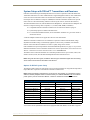
System Setup with DXLink™ Transmitters and Receivers...................................................... 83
Power Budget Planning for Systems with DXLink Boards...................................................... 86
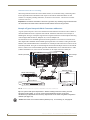
Connecting Switching Systems with DXLink Connectors ....................................................... 87
Attaching Cables ................................................................................................................... 88
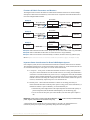
Integrating DXLink TXs and RXs in NetLinx Studio ............................................................... 91
Serial Data Transfer and IR Flow Control............................................................................... 92
Epica DGX SC Optical Boards........................................................................... 93
Epica DGX SC Optical Boards – Specifications ...................................................................... 94
System Setup with DGX Fiber Modules................................................................................. 95
Safety Recommendations for Laser Products ........................................................................ 96
Attaching Cables ................................................................................................................... 96
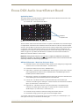
Enova DGX Audio Insert/Extract Board............................................................ 99
Enova DGX Audio Insert/Extract Board – Specifications ..................................................... 100
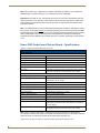
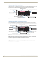
Setting Audio Connectors to Insert or Extract..................................................................... 103
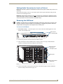
Removing the AIE Board ..................................................................................................... 103
Setting the DIP Switches ..................................................................................................... 104
Reinstalling the AIE Board ................................................................................................... 105
Attaching Wires ................................................................................................................... 105
Testing/Checking the Insert/Extract Functionality ............................................................... 106
AIE Board Troubleshooting ................................................................................................. 107
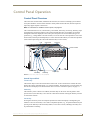
Control Panel Operation................................................................................. 109
Control Panel Overview....................................................................................................... 109
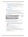
Executing Switches .............................................................................................................. 113
Changing the Virtual Matrix ................................................................................................ 114
Disconnecting Switches ....................................................................................................... 115
Verifying Signal Status......................................................................................................... 116
Defining and Executing Global Presets ............................................................................... 117
Executing Local Presets ....................................................................................................... 119
Locking and Unlocking......................................................................................................... 120
Setup Options ..................................................................................................................... 122
System Error Codes and Troubleshooting ........................................................................... 126
NetLinx® Integrated Control.......................................................................... 129
WebConsole Overview ........................................................................................................ 129
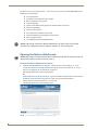
Opening the NetLinx WebConsole ...................................................................................... 130
Getting a DHCP IP Address ................................................................................................. 131
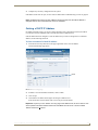
Setting a Static IP Address .................................................................................................. 132
ii
Instruction Manual – Enova DGX 8/16/32 Digital Media Switchers
Contents
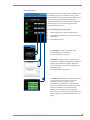
Enova DGX WebConsole Interface ..................................................................135
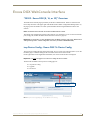
“05002 - Enova DGX [8, 16, or 32]” Overview .................................................................... 135
icsp Device Config - Enova DGX 16 Device Config ............................................................. 135
Upgrade - Upgrade Log - Enova DGX 16 Upgrade Log ...................................................... 136
Upgrade - Upgrade Status - Enova DGX 16 Upgrade Status............................................... 136
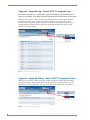
Upgrade - Upgrade Config - Enova DGX 16 Upgrade Config ............................................. 137
IP Control - Home - Enova DGX 16 Home ........................................................................... 137
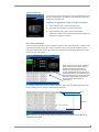
IP Control - Configuration - Enova DGX 16 Configuration................................................... 138
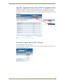
IP Control - Preferences - Enova DGX 16 Preferences......................................................... 139
IP Control - Controller - XBar Controller.............................................................................. 140
Firmware Upgrade & Info for Network Admin ................................................143
Overview ............................................................................................................................. 143
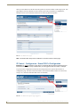
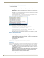
Preparation Checklist for Firmware Upgrade ...................................................................... 143
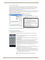
Sending Firmware (*.KIT) Files to the Enova DGX ............................................................... 144
Embedding the XBar Applet ............................................................................................... 146
Changing the Proxy Setting ................................................................................................ 147
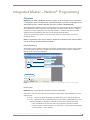
Integrated Master – NetLinx® Programming ..................................................149
Overview ............................................................................................................................. 149
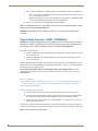
Digital Media Switchers: SEND_COMMANDs ..................................................................... 150
Appendix A – DGX Configuration Software ....................................................155
DGX Configuration Software Overview............................................................................... 155
Software Installation on PC and Enova DGX Connection .................................................... 155
Scaler Mode View................................................................................................................ 157
Scaler Override View ........................................................................................................... 159
EDID Programmer View ...................................................................................................... 164
Device between HDMI Output Board and Monitor ............................................................. 169
HDCP Settings View ............................................................................................................ 170
Terminal View...................................................................................................................... 171
Appendix B – Managing Configuration Files ...................................................173
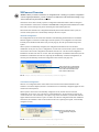
XNConnect Overview .......................................................................................................... 174
Installing and Launching XNConnect ................................................................................... 175
Discovering a System .......................................................................................................... 176
Opening an .xcl Configuration File ...................................................................................... 177
Navigating the Interface...................................................................................................... 178
Modifying an .xcl Configuration File.................................................................................... 179
Loading an .xcl Configuration File ....................................................................................... 182
Appendix C – APDiagnostics ...........................................................................185
APDiagnostics Overview ..................................................................................................... 185
Installing APDiagnostics ...................................................................................................... 185
Modes ................................................................................................................................. 187
Main Screen and Menus ...................................................................................................... 187
Communications .................................................................................................................. 196
Instruction Manual – Enova DGX 8/16/32 Digital Media Switchers
iii
Contents
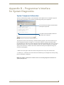
Appendix D – Programmer’s Interface for System Diagnostics ...................... 197
System Component Information .......................................................................................... 197
Using BCS to Access System Diagnostic Information........................................................... 198
Splash Screen Examples ...................................................................................................... 199
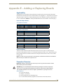
Appendix E – Adding or Replacing Boards..................................................... 203
Applicability......................................................................................................................... 203
Procedure Overview ............................................................................................................ 203
Safety Recommendations for Laser Products ...................................................................... 204
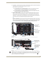
Adding or Replacing a Board............................................................................................... 204
Board Troubleshooting ........................................................................................................ 208
Appendix F – Program Run Disable Mode...................................................... 209
Program Run Disable (PRD) Mode ....................................................................................... 209
Removing the CPU Board and Setting the DIP Switch......................................................... 210
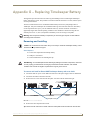
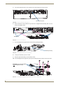
Appendix G – Replacing Timekeeper Battery................................................. 213
Removing and Installing....................................................................................................... 213
Appendix H – DGX_SHELL Commands ........................................................... 217
Overview DGX_SHELL Commands ...................................................................................... 217
Basic DGX_SHELL Commands.............................................................................................. 218
iv
Instruction Manual – Enova DGX 8/16/32 Digital Media Switchers
ESD Warning
ESD Warning
To avoid ESD (Electrostatic Discharge) damage to sensitive components, make sure you are properly
grounded before touching any internal materials.
When working with any equipment manufactured with electronic devices, proper ESD grounding
procedures must be followed to make sure people, products, and tools are as free of static charges as
possible. Grounding straps, conductive smocks, and conductive work mats are specifically designed for
this purpose.
Anyone performing field maintenance on AMX Enova DGX Digital Media Switchers should use an
appropriate ESD field service kit complete with at least a dissipative work mat with a ground cord and a
UL listed adjustable wrist strap with another ground cord. These items should not be manufactured
locally, since they are generally composed of highly resistive conductive materials to safely drain static
charges, without increasing an electrocution risk in the event of an accident. ESD protective equipment
can be obtained from 3M™, Desco®, Richmond Technology®, Plastic Systems®, and other such
vendors.
Instruction Manual – Enova DGX 8/16/32 Digital Media Switchers
1
Important Safety Information and Instructions
Important Safety Information and Instructions
When using and installing your AMX product, adhere to the following basic safety precautions. For
more information about operating, installing, or servicing your AMX product, see your product
documentation.
Read and understand all instructions before using and installing AMX products.
Use the correct voltage range for your AMX product.
There are no user serviceable parts inside an AMX product; service should only be done by
qualified personnel.
If you see smoke or smell a strange odor coming from your AMX product, turn it off
immediately and call technical support.
For products with multiple power supplies in each unit, make sure all power supplies are
turned on simultaneously.
Use surge protectors and/or AC line conditioners when powering AMX products.
Only use a fuse(s) with the correct fuse rating in your enclosure.
Make sure the power outlet is close to the product and easily accessible.
Make sure the product is on or attached to a stable surface.
Turn off equipment before linking pieces together, unless otherwise specified in that product’s
documentation.
For safety and signal integrity, use a grounded external power source and a grounded power
connector.
Turn off and unplug an enclosure before adding or removing boards, unless otherwise
specified in that product’s documentation.
To avoid shock or potential ESD (Electrostatic Discharge) damage to equipment, make sure
you are properly grounded before touching components inside an AMX product.
2
Instruction Manual – Enova DGX 8/16/32 Digital Media Switchers
Information et directives de sécurité importantes
Information et directives de sécurité
importantes
Veuillez vous conformer aux directives de sécurité ci-dessous lorsque vous installez et utilisez votre
appareil AMX. Pour de plus amples renseignements au sujet de l’installation, du fonctionnement ou de
la réparation de votre appareil AMX, veuillez consulter la documentation accompagnant l’appareil.
Lisez attentivement toutes les directives avant d’installer et d’utiliser les appareils AMX.
Le voltage doit être approprié à l’appareil AMX.
Les appareils AMX ne contiennent aucune pièce réparable par l’usager; la réparation ne doit
être effectuée que par du personnel qualifié.
Si de la fumée ou une odeur étrange se dégagent d’un appareil AMX, fermez-le
immédiatement et appelez le Service de soutien technique.
Veillez à ce que tous les blocs d’alimentation des appareils dotés de blocs d’alimentation
multiples dans chaque unité soient allumés simultanément.
Servez-vous de protecteurs de surtension ou de conditionneurs de lignes à courant alternatif
lorsque vous mettez les appareils AMX sous tension.
Placez uniquement des fusibles de calibre exact dans les boîtiers.
Veillez à ce que la prise de courant soit proche de l’appareil et facile d’accès.
Veillez à ce que votre appareil AMX soit installé sur une surface stable ou qu’il
y soit fermement maintenu.
Fermez toutes les composantes de l’équipement avant de relier des pièces, à moins
d’indication contraire fournie dans la documentation de l’appareil.
Par mesure de sécurité et pour la qualité des signaux, servez-vous d’une source d’alimentation
externe mise à la terre et d’un connect d’alimentation mis à la terre.
Fermez et débranchez le boîtier avant d’ajouter ou d’enlever des plaquettes, à moins
d’indication contraire fournie dans la documentation du appareil.
Pour éviter les chocs ou les dommages éventuels causés à l’équipement par une décharge
électrostatique, veillez à ce le dispositif oit bien relié à la terre avant de toucher les
composantes se trouvant à l’intérieur d’un appareil AMX.
Instruction Manual – Enova DGX 8/16/32 Digital Media Switchers
3
Notices
Notices
Copyright Notice
AMX© 2013 (Rev K), all rights reserved. No part of this publication may be reproduced, stored in a
retrieval system, or transmitted, in any form or by any means, electronic, mechanical, photocopying,
recording, or otherwise, without the prior written permission of AMX. Copyright protection claimed
extends to AMX hardware and software and includes all forms and matters copyrightable material and
information now allowed by statutory or judicial law or herein after granted, including without
limitation, material generated from the software programs which are displayed on the screen such as
icons, screen display looks, etc. Reproduction or disassembly of embodied computer programs or
algorithms is expressly prohibited.
Liability Notice
No patent liability is assumed with respect to the use of information contained herein.
While every precaution has been taken in the preparation of this publication, AMX assumes no
responsibility for error or omissions. No liability is assumed for damages resulting from the use of the
information contained herein.
Further, this publication and features described herein are subject to change without notice.
US FCC Notice
The United States Federal Communications Commission (in 47CFR 15.838) has specified that the
following notice be brought to the attention of the users of this product.
Federal Communication Commission Radio Frequency Interference Statement:
“This equipment has been tested and found to comply with the limits for a Class A digital device,
pursuant to Part 15 of the FCC Rules. These limits are designed to provide reasonable protection
against harmful interference when the equipment is operated in a commercial environment. This
equipment generates, uses, and can radiate radio frequency energy and, if not installed and used in
accordance with the instruction manual, may cause harmful interference to radio communications.
Operation of this equipment in a residential area is likely to cause harmful interference in which case
the user will be required to correct the interference at his own expense.
If necessary, the user should consult the dealer or an experienced radio/television technician for
additional suggestions. The user may find the booklet, How to Identify and Resolve Radio-TV
Interference Problems, prepared by the Federal Communications Commission to be helpful.”
This booklet is available from the U.S. Government Printing Office, Washington, D.C. 20402, Stock N.
004-000-00345-4.
Use shielded cables. To comply with FCC Class A requirement, all external data interface cables and
adapters must be shielded.
4
Instruction Manual – Enova DGX 8/16/32 Digital Media Switchers
Notices
Trademark Notices
AMX®, Enova®, AutoPatch®, NetLinx®, DXLink™, InstaGate Pro®, and SmartScale® are trademarks
of AMX.
Windows is a registered trademark of Microsoft Corporation in the United States and other countries.
TeraTerm is a copyright product of T. Teranishi and TeraTerm Project.
PuTTY is a copyright product of Simon Tatham.
HyperTerminal® is a copyright product of Hilgraeve Inc.
3M®, Desco®, Richmond Technology®, and Plastic Systems® are registered trademarks.
Ethernet® is a registered trademark of the Xerox Corporation.
ENERGY STAR® is a registered trademark of the U.S. Department of Energy and the
U.S. Environmental Protection Agency.
Other products mentioned herein may be the trademarks of their respective owners.
Lithium Batteries Notice
Switzerland requires the following notice for products equipped with lithium batteries. This notice is not
applicable for all AMX equipment.
Upon shipment of products to Switzerland, the requirements of the most up-to-date Swiss Ordinance
Annex 2.15 of SR 814.81 will be met including provision of the necessary markings, documents, and
annual reports relative to the disposal of the batteries to the Swiss Authorities.
Warnings and Cautions
This manual uses the following conventions and icons to draw attention to actions or conditions that
could potentially cause problems with equipment or lead to personal risk.
ESD Warning: The icon to the left indicates text regarding potential danger associated with the
discharge of static electricity from an outside source (such as human hands) into an integrated
circuit, often resulting in damage to the circuit.
Warning: The icon to the left indicates text that warns readers against actions or conditions that
could cause potential injury to themselves.
Caution: The icon to the left indicates text that cautions readers against actions that could cause
potential injury to the product or the possibility of serious inconvenience.
Instruction Manual – Enova DGX 8/16/32 Digital Media Switchers
5
Notices
6
Instruction Manual – Enova DGX 8/16/32 Digital Media Switchers
Product Overview and General Specifications
Product Overview and General Specifications
Applicability Notice
The information in this manual applies to the following Enova® DGX Digital Media Switcher
enclosures, plus input, output, and expansion boards, which can be ordered to create custom systems. All
of the boards are compatible with any Enova DGX enclosure.
Note: All Enova DGX Switchers ship with a standard front control panel.
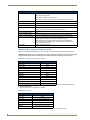
Enova DGX 8 Enclosure (4 RU)
Configuration
FG #
Model
8x8
FG1058-08
AVS-ENOVADGX8-ENC, ENOVADGX 8 ENC
Enova DGX 16 Enclosure (4 RU)
Configuration
FG #
Model
16x16
FG1058-16
AVS-ENOVADGX16-ENC, ENOVADGX 16 ENC
Enova DGX 32 Enclosure (6 RU)
Configuration
FG #
Model
32x32
FG1059-33
AVS-ENOVADGX32-ENC-A, ENOVADGX 32 ENC
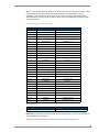
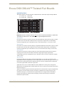
Enova DGX Digital Media Switchers Standard Input and Output Boards
Enova DGX Switchers currently support three standard Enova input and output board types: DVI,
HDMI, DXLink Twisted Pair (RJ-45 transport), as well as Epica DGX SC Optical Boards. Each board
fills one of the standard I/O board slots and has four connectors. Within a system, a source device
connected to any of the input boards can be routed to any destination device connected to any of the
output boards (check the board chapters for important signal information when routing between board
types).
For general board information, see page 14 and page 33.
For specific board information, see the applicable board chapter in this manual.
Enova DGX HDMI Boards (page 63)
Type
FG #
Model
HDMI w/ HDCP Input
FG1058-540
AVS-ENOVADGX32-VI-HDMI
HDMI w/ HDCP and SmartScale Output
FG1058-550
AVS-ENOVADGX32-VO-HDMI
Enova DGX DVI Boards (page 73)
Type
FG #
Model
DVI w/HDCP Input
FG1058-600
AVS-ENOVADGX32-VI-DVI
DVI w/HDCP and SmartScale Output
FG1058-610
AVS-ENOVADGX32-VO-DVI
Enova DGX DXLink™ Twisted Pair Boards* (page 79)
Type
FG #
Model
DXLink w/HDCP Input
FG1058-570
AVS-ENOVADGX32-VI-DXLINK
DXLink w/HDCP Output
FG1058-580
AVS-ENOVADGX32-VO-DXLINK
* Enova DXLink™ Twisted Pair Boards must be used in conjunction with DXLink™ Twisted Pair
Transmitters and Receivers or other AMX DXLink™ signal management solutions. For model numbers
of compatible Transmitters and Receivers, see page 81. For system setup information, see page 82.
Instruction Manual – Enova DGX 8/16/32 Digital Media Switchers
7
Product Overview and General Specifications
Epica DGX SC Optical Boards** (page 95)
Type
FG #
Model
SC Optical Input
FG1056-500
AVS-EPDGX32-OI-SC
SC Optical Output
FG1056-510
AVS-EPDGX32-OO-SC
** Epica DGX SC Optical Boards work in Enova DGX enclosures and must be used in conjunction with
DGX Fiber Transmitters and Receivers. For model numbers of compatible modules, see page 96. For
system setup information, see page 97.
Enova DGX Expansion Boards
Enova DGX Switchers currently support the Audio Insert/Extract Board. This board can be installed in
either or both of the expansion slots. Audio Insert/Extract Boards will not fit in a standard input or output
board slot.
Enova DGX Audio Insert/Extract Board (page 101)
Type
FG #
Model
Audio Insert/Extract
FG1058-700
AVS-ENOVADGX32-AUD-INS-EXT
Product Notes
The Enova DGX Digital Media Switcher includes an integrated NetLinx Central Control Processor,
supports InstaGate Pro®, DXLink™ Technology, and SmartScale® on every output, and manages and
distributes analog and digital audio and video including HDMI/HDCP, control, and Ethernet.
The Enova DGX Switcher is available as a custom system, which means it can be ordered in input to
output configuration sizes that fit your installation and contain an assortment of input, output, and
expansion boards in a single enclosure.
Note: Because Enova DGX Switchers are available as custom systems, the illustrations in this
manual may differ from the model(s) you purchased.
Features of the Enova DGX Digital Media Switcher
HDMI, DVI, DXLink™, and Audio
True HDMI switching, allowing any input to be switched to any or all outputs (including
SC Optical).
Incorporates HDMI® technology – HDMI, DVI, and DXLink™ Twisted Pair Boards.
HDCP 1.4 compatible (all boards except SC Optical Boards which cannot pass HDCP).
Supports uncompressed video resolutions up to 1920x1200 @ 60 Hz, including HDTV up
to 1080p.
DGX Technology provides a common signal transport and matrix switching layer that
transcodes between analog and digital signals.
HDMI and DVI Output Boards, as well as compatible DGX Fiber Receivers, feature
SmartScale® Technology which automatically responds to the display’s declared EDID
information and scales the video to the best resolution and video parameters for that display
without manual setup.
Pre-loaded with the most common EDID settings on each switcher input connector (other than
fiber connectors) to emulate display response when queried, which ensures that transmission of
the video from the source device is working.
8
Instruction Manual – Enova DGX 8/16/32 Digital Media Switchers
Product Overview and General Specifications
HDMI, DVI, DXLink™, and Audio (continued)
Custom EDID settings can be loaded on each DVI and HDMI input with DGX Configuration
Software (available at www.amx.com).
InstaGate Pro® Technology – Easily integrate HDCP into system designs and enjoy hassle-
free matrix switching to all compliant displays. No tools, no delays, and no key constraints
– it just works.
DXLink™ Twisted Pair Boards provide transport over twisted pair cable.
The Audio Insert/Extract (expansion) Board can be set to insert/extract audio into/out of video
input or output boards.
Digital Media Switcher
The available input/output range is 4x4 to 8x8 for the Enova DGX 8, 4x4 to 16x16 for the
Enova DGX 16, and 4x4 to 32x32 for the Enova DGX 32 (all come in increments of 4 with
upgrade potential to the individual product’s capacity).
System self-diagnostics – power monitoring, fan control and monitoring, signal and
temperature sensing. Ships with APDiagnostics software – monitors, displays, and collects
advanced diagnostic information.
Local presets allow quick recall of a pre-programmed set of switches with a single command;
multiple presets can exist within a system at the same time.
Global presets allow quick recall of a comprehensive snapshot of all switches.
Fully redundant (hot-swappable) power supplies (RPS) with independent power paths for
maximum reliability.
Rack mounting ears integral to product design.
Control Ports
Integrated NetLinx® Master is an NI-3100 Class Controller.
LAN 100/1000 port, the network connection for the integrated Master.
Program port (USB mini-AB) used for initial setup with NetLinx Studio.
Control port (standard RS-232) for direct matrix switching control.
Control port (USB mini-B) used as a virtual COM port for serial communication with a PC.
Additional Features Available with Epica DGX SC Optical Boards
Designed for use with single strand multimode fiber.
Use in conjunction with DGX Fiber Transmitters and Receivers to send video and audio over
a single fiber cable up to a total of 6000 feet (1828.8 m), i.e., 3000 feet (914.4 m) from the
source to the Enova DGX enclosure and 3000 feet from the Enova DGX enclosure to the
destination.
DGX SC Optical Boards support DVI (non-HDCP) and HDMI (non-HDCP) formats. They
also support RGBHV, RGBS, RGsB, and Y/Pb/Pr (Y/Pb/Pr including 1080p) video,
depending on the type of DGX Fiber Modules used with them.
DGX SC Optical Boards support embedded analog stereo audio signals (unbalanced stereo
@ a sample rate of 48 kHz) and digital audio signals (PCM over S/PDIF @ 32 kHz, 44.1 kHz,
48 kHz, as well as 96 kHz, which requires a minimum video resolution of 800x600 @ 60 Hz).
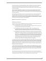
Product Support
AMX Limited Lifetime Warranty included (see www.amx.com).
24-hour technical support.
Instruction Manual – Enova DGX 8/16/32 Digital Media Switchers
9
Product Overview and General Specifications
Control Features of the Enova DGX Digital Media Switcher
Each Enova DGX enclosure includes an AMX NetLinx 3100 Class Control Processor. Each enclosure
also features a front control panel for an added level of convenience; the panel can be used for
controlling the system’s switches. In addition, several other control options are available. Multiple
control methods can be used on the same system.
Integrated NetLinx Master with control via a WebConsole interface
Includes the XBar Controller
Server (LAN) connection through the LAN 100/1000 port on the CPU
Front control panel (standard on all enclosures).
Compatible with a number of AMX control devices (for NetLinx control programming
information, see page 151 and the instruction manual for the specific AMX control device).
Select AMX NetLinx commands supported
Supports AMX AutoPatch’s simple BCS (Basic Control Structure)* serial control protocol
Supports AMX AutoPatch’s XNNet protocol
Supports third-party controllers
BCS tunneling access support over TCP/IP
* BCS commands are sent as ASCII characters through the Control (RS-232) port.
Note: Features and specifications described in this document are subject to change without notice.
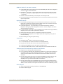
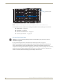
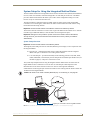
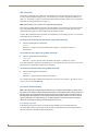
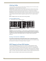
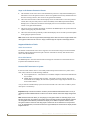
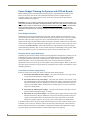
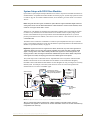
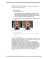
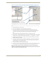
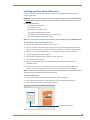
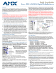
Common Applications
Enova DGX Switchers fit in a broad range of digital and analog environments and are controllable from
a variety of sources. The Enova DGX Switcher can route and transmit pure high resolution analog and
digital video up to 3,000 feet (914.4 m) making it the perfect solution for commercial or residential
installations, government agencies, command-and-control environments, universities, hospitals, casinos,
retail environments, or any facility that demands the highest quality video be shared between rooms or
even buildings.
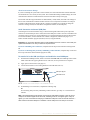
FIG. 1 Application featuring the Enova DGX 16
10
Instruction Manual – Enova DGX 8/16/32 Digital Media Switchers
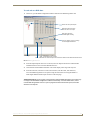
Product Overview and General Specifications
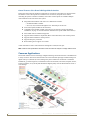
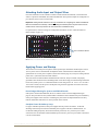
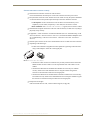
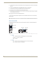
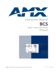
Front View
The enclosure, which is the structural basis of an Enova DGX Switcher, can be controlled using the
integrated NetLinx Central Control Processor, standard front control panel, control software, or an
external controller. For additional information on control options, see page 22.
LCD
Control Dial
Input Keys
Power Indicator LED
Output Keys
Control Keys
FIG. 2 Front view of an Enova DGX 32 enclosure
Power Indicator LED on Front of Enclosure
The Power Indicator LED on the front of the enclosure indicates the power status of the redundant power
system within an Enova DGX Switcher as follows:
Green – both power supplies are powered on
Red – one of the power supplies is not receiving power or has failed
Off – neither power supply is receiving power
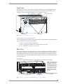
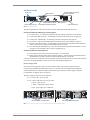
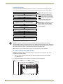
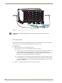
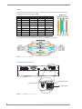
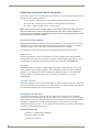
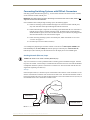
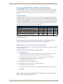
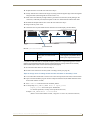
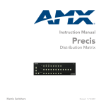
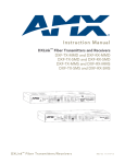
Rear View
The enclosure’s appearance, as viewed from the rear, will vary depending on the number and types of
input, output, and expansion boards present. The Enova DGX 8 enclosure in FIG. 3 is fully loaded for
8x8 switching. The Enova DGX 16 enclosure in FIG. 4 is fully loaded for 16x16 switching. The Enova
DGX 32 enclosure in FIG. 5 is fully loaded for 32x32 switching. In addition, the illustrations each show
two expansion boards.
Enova DGX 8
Input boards (up to 2 in the input board slots)
Output boards (up to 2 in the output board slots)
Note: If the enclosure has an
empty input or output board
slot (which is numbered for
an additional board), it can be
used to expand the system,
to a maximum of 2 input and
2 output boards. The blank
plates under the input and
output board slots cannot be
removed.
AC
AC
DC
F LT
Serial numbers
MAC address
CPU/Control board
DC
F LT
Power supplies
Audio Insert/Extract Boards
in expansion slots
FIG. 3 Rear view of a fully loaded Enova DGX 8 enclosure with two expansion boards
Instruction Manual – Enova DGX 8/16/32 Digital Media Switchers
11
Product Overview and General Specifications
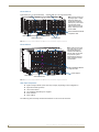
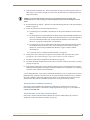
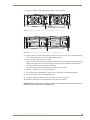
Enova DGX 16 and 32 rear view
Enova DGX 16
Input boards (up to 4 in input board slots)
Output boards (up to 4 in output board slots)
Note: If the enclosure has
any empty input or output
board slots (which are
numbered for additional
boards), they can be used
to expand the system.
If the expansion slots are
empty, expansion boards
can be added.
AC
AC
DC
DC
F LT
F LT
MAC address
Serial numbers
CPU/Control board
Audio Insert/Extract Boards
in expansion slots
Power supplies
FIG. 4 Rear view of a fully loaded Enova DGX 16 enclosure with two expansion boards
Enova DGX 32
Input boards (up to 8)
Output boards (up to 8)
Note: If the enclosure has
any empty input or output
board slots (which are
numbered for additional
boards), they can be used
to expand the system.
If the expansion slots are
empty, expansion boards
can be added.
Audio Insert/Extract Boards
in expansion slots
Power supplies
MAC address
CPU/Control board
Serial numbers
FIG. 5 Rear view of a fully loaded Enova DGX 32 enclosure with two expansion boards
Rear View Components
Input and output boards (some slots may be empty, depending on the configuration)
Expansion boards (optional)
CPU/Control board
Two standard redundant power supplies
Serial numbers
MAC address
The following sections briefly introduce the hardware on the rear of the enclosure.
12
Instruction Manual – Enova DGX 8/16/32 Digital Media Switchers
Product Overview and General Specifications
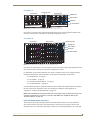
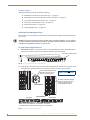
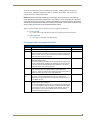
CPU/Control Board
RJ-45 ports
MAC address
Control (USB mini-B) port
System Status indicator
Program (USB mini-AB) port
and LED indicators
SD card slot
Control (DB-9, RS-232 serial) port
LAN 100/1000 port
FIG. 6 CPU/Control board
The CPU/Control board is on the left rear of the enclosure, directly below the input connectors.
Each CPU includes the following port and slot options:
Two RJ-45 ports – for connecting autonomous devices (linking of enclosures is not allowed)
Control port* (DB-9, RS-232) – for attaching an external serial control device (see page 52)
Control port* (USB mini-B) – for attaching an external control device (see page 54)
SD card slot – ships with an installed Micro SD memory card for CPU backup (see page 59)
Program port (USB mini-AB) – for establishing a connection from the Integrated NetLinx Master to
the PC’s COM port (see page 40) and for initial setup of the system
LAN 100/1000 port (Ethernet RJ-45) – the connection from the integrated NetLinx Master to a LAN
(see page 41) for all runtime control, NetLinx programming, etc.
Each CPU includes four LED indicators:
System Status LED (to the left of the Control ports) – for system status
Status, Output, and Input LEDs (above Program connector) – indicate system communication status
and when data is sent and received (for modes and blink patterns, see page 40)
* The two Control ports provide direct control of matrix switcher processing (they do not work on the same layer
of control as the integrated Master, which uses the LAN 100/1000 and Program ports).
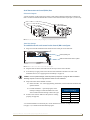
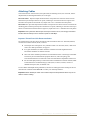
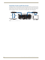
Power Supply Units
Each of the power supply units on the rear of the enclosure (FIG. 7) has a power receptacle that will
accept all major international standard power sources. (US power cords are included with all shipments
unless ordered otherwise.) Maximum power specifications are provided on the power supply receptacles.
For information on applying power, see page 35.
The power supply units have two LED indicators:
AC: Green LED – power is good
DC: The DC indicator uses a tri-color LED
Green – power is good
Amber – temperature is above normal
Red – power supply is in a fault state
Enova DGX 8/16 - Indicator LEDs
Enova DGX 32 - Indicator LEDs
FIG. 7 Power supply receptacles for Enova DGX 8/16 (left) and Enova DGX 32 (right)
Instruction Manual – Enova DGX 8/16/32 Digital Media Switchers
13
Product Overview and General Specifications
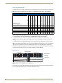
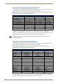
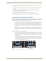
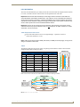
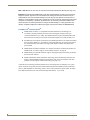
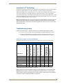
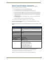
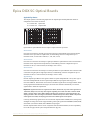
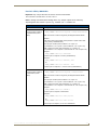
Input and Output Boards
A single enclosure can handle a combination of signals depending on the types of input and output boards.
Note: All boards in the table below are HDCP 1.4 compatible except for the SC Optical Boards.
Input: HDMI
*
*
Output: HDMI
*
Input: DVI
Output: DVI
Input and Output: DXLink^
Input and Output: SC Optical^^
*
**
**
Deep Color
3D Video
Analog Stereo Audio
Discrete Digital Audio
Analog Video
Embedded Audio from
Audio Insert Extract Board
Embedded Audio
DVI-D w/out HDCP
DVI-D w/HDCP
HDMI w/out HDCP
HDMI w/HDCP
I/O Board Types
Signal Types
Input and Output Boards and Supported Signals
***
***
* HDMI Boards require a cable adapter to support single-link DVI signals.
** For a DVI Board to support embedded audio on an HDMI signal, the EDID must be updated.
*** Supported analog video signals include RGBHV, RGBS, RGsB, and Y/Pb/Pr in and RGBHV out.
^ Signals supported by DXLink Twisted Pair Boards depend on the type of DXLink Transmitters and Receivers
used.
^^ Signals supported by SC Optical Boards depend of the type of DGX Fiber Transmitters and Receivers used.
Note: The DXLink Twisted Pair Boards also support embedded power, NetLinx control, and Ethernet.
All signals are automatically converted to the destination device’s format, with DXLink Twisted Pair
Transmitters and Receivers used for transport of signals with DXLink Boards and DGX Fiber Transmitters
and Receivers used in the conversion process for the DGX SC Optical Boards.
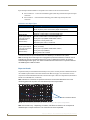
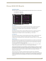
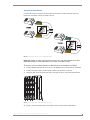
Enova DGX 8
Input boards
Numbering plate
Output boards
DXLink Board
DVI Board
HDMI Board
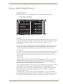
FIG. 8 DGX DXLink, DVI, and HDMI Input and Output Boards
Enova DGX 8 enclosures have 4 horizontal I/O board slots (2 slots each for input and output boards with
four connectors each), allowing for a maximum configuration of 8x8.
14
Instruction Manual – Enova DGX 8/16/32 Digital Media Switchers
Product Overview and General Specifications
Enova DGX 16
Input boards
Numbering plate
Output boards
HDMI Board
DXLink Board
DVI Board
SC Optical Board
FIG. 9 DGX HDMI, DXLink, DVI, and DGX SC Optical Input and Output Boards
Enova DGX 16 enclosures have 8 horizontal I/O board slots (4 slots each for input and output boards
with four connectors each), allowing for a maximum configuration of 16x16.
Enova DGX 32
Input boards
Output boards
Numbering plate
HDMI Board
DXLink Board
DVI Board
SC Optical Board
FIG. 10 HDMI, DXLink, DVI, and SC Optical Input and Output Boards
Enova DGX 32 enclosures have 16 vertical I/O board slots (8 slots each for input and output boards with
four connectors each), allowing for a maximum configuration of 32x32.
For information on the boards included in your system, including connector types, cabling directions,
installation considerations, and specifications, see the specific board chapter in this manual.
HDMI Boards – see page 63
DVI Boards – see page 73
DXLink Twisted Pair Boards – see page 79
SC Optical Boards – see page 95
If a system has empty input or output board slots (which are numbered for additional inputs and outputs),
the slots can be used to expand the system. For information on adding or replacing boards, see
“Appendix E – Adding or Replacing Boards” on page 205.
Note: Audio Insert/Extract (expansion) Boards are also available. They provide audio insertion and
extraction functionality and are used in conjunction with HDMI, DVI, and DXLink Boards (see
“Expansion Boards” on page 16).
Input and Output Board Connectors
The connectors on the input and output boards are the attachment points for source and destination
devices that connect to the system. Viewed from the rear of the enclosure, the input connectors (for
attaching sources) are on the left, and the output connectors (for attaching destinations) are on the right.
Instruction Manual – Enova DGX 8/16/32 Digital Media Switchers
15
Product Overview and General Specifications
Input and output channel numbers correspond to the connectors and are located as follows:
Enova DGX 8/16 – on the vertical numbering plate (metal strip) between the input and output
connectors.
Enova DGX 32 – on the horizontal numbering plate (metal strip) directly above the
connectors.
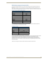
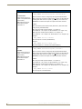
Connectors and Signal Types
Connector
Supported Signals
HDMI
• HDMI with or without HDCP or embedded digital audio
DVI
• DVI-D (single link) with or without HDCP
• DVI-D (single link) with or without HDCP (adapter cable required)
• HDMI with or without HDCP or embedded digital audio*
DXLink (RJ-45)
• HDMI with or without HDCP or embedded digital audio
(Signal support depends
on the type of DXLink
Transmitters and
Receivers used.)
• DVI with or without HDCP or embedded digital audio
• Analog video input (RGBHV, RGBS, RGsB, Y/Pb/Pr)
• Digital audio or analog stereo audio
• Embedded power, NetLinx, and Ethernet
SC Fiber
• HDMI (non-HDCP) output as DVI (adapter cable required)
(Signal support depends
on the type of DGX Fiber
Transmitters and
Receivers used.)
• DVI-D (non-HDCP)
• Analog video input (RGBHV, RGBS, RGsB, Y/Pb/Pr)
• Analog video output (RGBHV)
• Analog stereo audio or S/PDIF
* For a DVI connector to support embedded audio on an HDMI signal, the EDID must be updated.
Note: An analog stereo audio signal from a pluggable 3-position terminal block connector can be
inserted from an Audio Insert/Extract Board onto a DVI or HDMI signal (replaces any existing
embedded digital audio signal). The Audio Insert/Extract Board also works in conjunction with DVI
and HDMI signals on DXLink boards.
Expansion Boards
Expansion boards provide additional functionality to the system. Currently the Enova DGX Switcher has
one available expansion board: the Audio Insert/Extract Board (see page 101). This board is used in
conjunction with the embedded audio feed on the first four input or first four output boards (the standard
boards must be HDMI, DVI, or DXLink).
Note: Numbers for connectors on expansion boards are on the boards themselves not on the
numbering plate at the top which is for the standard input and output boards.
Audio Insert/Extract Boards
FIG. 11 Audio Insert/Extract (expansion) Boards – shown with a variety of video input and output boards
Note: Enova DGX 8 only – Depending on location, AIE Board connectors 1-8 correspond to
standard input or output connectors 1-8. Connectors 9-16 are inoperable.
16
Instruction Manual – Enova DGX 8/16/32 Digital Media Switchers
Product Overview and General Specifications
If the expansion board slots in an enclosure are empty, the slots can be used for expansion boards to
expand the functionality of the system. The procedure for installing/replacing an Audio Insert/Extract
Board and setting it for insertion or extraction starts on page 105.
Caution: Standard input and output boards will not fit in the expansion slots.
Important: Setting the DIP switches is the only mechanism for configuring the Audio Insert/Extract
Board to either insert or extract audio. Therefore, setting the switches (which requires removal of the
board from the enclosure) needs to be done at the time of installation setup.
Serial Numbers
The serial numbers are normally located on the rear of the enclosure on the left (for the Enova DGX 8,
see FIG. 3 on page 11; for the Enova DGX 16, see FIG. 4 on page 12; and for the Enova DGX 32, see
FIG. 5 on page 12). Before installation, we recommend recording the serial number for the enclosure
(and for each module and/or wallplate if applicable) in an easily accessible location.
MAC Address
The MAC address for the system is located directly above the Control (DB-9 serial) port on the CPU.
Instruction Manual – Enova DGX 8/16/32 Digital Media Switchers
17
Product Overview and General Specifications
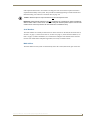
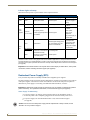
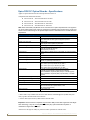
Enova DGX 8 – General Specifications
Specifications
Parameter
Value
Approvals
CE, UL, cUL, FCC Class A, RoHS
AC Power per Supply
100 VAC to 240 VAC single phase, 50 Hz to 60 Hz
Power Consumption (max.)
977 Watts, with redundancy
1954 Watts, without redundancy
Power Consumption (typical)
145 Watts, fully loaded HDMI enclosure with redundancy
Power Consumption w/DXLink Power
(typical)
415 Watts*, fully loaded DXLink power enclosure with
redundancy
Thermal Dissipation (max.)
3334 BTU/hr., with redundancy
6667 BTU/hr., without redundancy
Thermal Dissipation (typical)
495 BTU/hr., fully loaded enclosure with redundancy
Thermal Dissipation w/DXLink Power
(typical)
1416 BTU/hr*, fully loaded DXLink power enclosure with
redundancy
Operational Temperature
32° F to 104° F (0° C to 40° C)
Storage Temperature
-22° F to 158° F (-30° C to 70° C)
Operational Humidity
5% to 85% RH (non-condensing)
Storage Humidity
0 to 90% RH (non-condensing)
MTBF
168,000 hrs.
Dimensions
15 in. (38.1 cm) depth; 16 in. (40.64 cm) depth with extractors
19 in. (48.26 cm) width including integral rack mounting ears
6.84 in. (17.37 cm) height (4 RU)
Weight
Approximately 35 lb. (15.9 kg) per loaded enclosure
Shipping Weight
Approximately 45 lb. (20.4 kg) per loaded enclosure
Per Channel Aggregate Data Rate (max.)
12.8 Gbps
Noise Level
<52.5 dBA @ 1 m (typical @ 25° C)
Airflow
Forced air (inlet on side; exhaust on side)
Compatible DXLink™ Transmitters
and Receivers
• DXLink HDMI Transmitter Modules
• DXLink Multi-Format Transmitter Modules
• DXLink Multi-Format Wallplate Transmitters
• DXLink Multi-Format Decor Style Wallplate Transmitter (US)
• DXLink HDMI Receiver Modules
Compatible Fiber Transmitters
and Receivers
• DGX Fiber DVI Transmitter and Receiver Modules
• DGX Fiber HD-15 Transmitter and Receiver Modules
* Use the Enova DGX Configuration Tool located at www.amx.com/enova to determine the power requirements
of a configuration and whether any of the DXLink Transmitters or Receivers should be powered with the local
power supply to maintain power supply redundancy in the Enova enclosure.
AMX reserves the right to modify its products and their specifications without notice.
18
Instruction Manual – Enova DGX 8/16/32 Digital Media Switchers
Product Overview and General Specifications
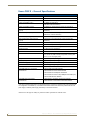
Enova DGX 16 – General Specifications
Specifications
Parameter
Value
Approvals
CE, UL, cUL, FCC Class A, RoHS
AC Power per Supply
100 VAC to 240 VAC single phase, 50 Hz to 60 Hz
Power Consumption (max.)
977 Watts, with redundancy
1954 Watts, without redundancy
Power Consumption (typical)
362 Watts, fully loaded HDMI enclosure with redundancy
Power Consumption w/DXLink Power
(typical)
835 Watts*, fully loaded DXLink power enclosure with
redundancy
Thermal Dissipation (max.)
3334 BTU/hr., with redundancy
6667 BTU/hr., without redundancy
Thermal Dissipation (typical)
1235 BTU/hr., fully loaded enclosure with redundancy
Thermal Dissipation w/DXLink Power
(typical)
2849 BTU/hr*, fully loaded DXLink power enclosure with
redundancy
Operational Temperature
32° F to 104° F (0° C to 40° C)
Storage Temperature
-22° F to 158° F (-30° C to 70° C)
Operational Humidity
5% to 85% RH (non-condensing)
Storage Humidity
0 to 90% RH (non-condensing)
MTBF
168,000 hrs.
Dimensions
15 in. (38.1 cm) depth; 16 in. (40.64 cm) depth with extractors
19 in. (48.26 cm) width including integral rack mounting ears
6.84 in. (17.37 cm) height (4 RU)
Weight
Approximately 55 lb. (24.95 kg) per loaded enclosure
Shipping Weight
Approximately 65 lb. (29.5 kg) per loaded enclosure
Per Channel Aggregate Data Rate (max.)
12.8 Gbps
Noise Level
<52.5 dBA @ 1 m (typical @ 25° C)
Airflow
Forced air (inlet on side; exhaust on side)
Compatible DXLink™ Transmitters
and Receivers
• DXLink HDMI Transmitter Modules
• DXLink Multi-Format Transmitter Modules
• DXLink Multi-Format Wallplate Transmitters
• DXLink Multi-Format Decor Style Wallplate Transmitter (US)
• DXLink HDMI Receiver Modules
Compatible Fiber Transmitters
and Receivers
• DGX Fiber DVI Transmitter and Receiver Modules
• DGX Fiber HD-15 Transmitter and Receiver Modules
* Use the Enova DGX Configuration Tool located at www.amx.com/enova to determine the power requirements
of a configuration and whether any of the DXLink Transmitters or Receivers should be powered with the local
power supply to maintain power supply redundancy in the Enova enclosure.
AMX reserves the right to modify its products and their specifications without notice.
Instruction Manual – Enova DGX 8/16/32 Digital Media Switchers
19
Product Overview and General Specifications
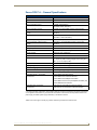
Enova DGX 32 – General Specifications
General Specifications
Parameter
Value
Approvals
CE, UL, cUL, FCC Class A, RoHS
AC Power per Supply
100 VAC to 240 VAC single phase, 50 Hz to 60 Hz
Power Consumption (max.)
1379 Watts, with redundancy
Power Consumption (typical)
585 Watts, fully loaded HDMI enclosure with redundancy
Power Consumption w/DXLink Power
(typical)
1751 Watts*, fully loaded DXLink power enclosure without
redundancy
2758 Watts, without redundancy
Thermal Dissipation (max.)
4705 BTU/hr., with redundancy
9410 BTU/hr., without redundancy
Thermal Dissipation (typical)
1996 BTU/hr., fully loaded enclosure with redundancy
Thermal Dissipation w/DXLink Power
(typical)
5975 BTU/hr*, fully loaded DXLink power enclosure without
redundancy
Operational Temperature
32° F to 104° F (0° C to 40° C)
Storage Temperature
-22° F to 158° F (-30° C to 70° C)
Operational Humidity
5% to 85% RH (non-condensing)
Storage Humidity
0 to 90% RH (non-condensing)
Dimensions
20.08 in. (51 cm) depth; 21.08 in. (53.54 cm) with extractors
19 in. (48.26 cm) width including integral rack mounting ears
10.45 in. (26.54 cm) height (6 RU)
Weight
Approximately 73 lb. (33.1 kg) per loaded enclosure
Shipping Weight
Approximately 83 lb. (37.6 kg) per loaded enclosure
MTBF
92,000 hrs.
Per Channel Aggregate Data Rate (max.)
12.8 Gbps
Noise Level
<54.0 dBA @ 1 m (typical @ 25° C)
Airflow
Forced air (inlet on sides; exhaust on back and top)
Compatible DXLink™ Twisted Pair
Transmitters and Receivers
• DXLink HDMI Transmitter Modules
• DXLink Multi-Format Transmitter Modules
• DXLink Multi-Format Wallplate Transmitters
• DXLink Multi-Format Decor Style Wallplate Transmitter (US)
• DXLink HDMI Receiver Modules
Compatible Fiber Transmitters and
Receivers
• DGX Fiber DVI Transmitter and Receiver Modules
• DGX Fiber HD-15 Transmitter and Receiver Modules
* Use the Enova DGX Configuration Tool located at www.amx.com/enova to determine the power requirements of
a configuration and whether any of the DXLink Transmitters or Receivers should be powered with the local power
supply to maintain power supply redundancy in the Enova enclosure.
AMX reserves the right to modify its products and their specifications without notice.
20
Instruction Manual – Enova DGX 8/16/32 Digital Media Switchers
Product Overview and General Specifications
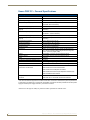
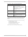
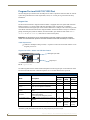
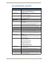
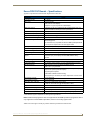
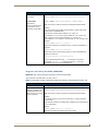
Enova DGX – NetLinx and Control Specifications
NetLinx and Control Specifications
Integrated Controller
LAN/ Ethernet Port
NetLinx on-board Master is an NI-3100 Class Controller
• TCP/IP uplink port (LAN 10/100/1000)
• Supports up to 64-port un-managed 10/100 Ethernet Switch*
• Static IP or DHCP/DNS, SSL, Auto-negotiating, Half/Full Duplex, Auto
MDI/MDI-X Crossover
• TCP/IP, UDP/IP, CIP, SMTP, Built-in Web server
• Includes support for DXLink™ devices
• RJ-45 connector
Processor
Memory
CPU 404 MIPS PowerPC
• SDRAM 256 MB
• NVRAM 1 MB
• Flash 2 GB
Program Port (USB)
USB Mini-AB connector (used for NetLinx Studio control)
Enclosure Control
Control Port (Serial)
Bidirectional RS-232
• Baud rates of 9600 (default), 19200, 38400, 57600
• DB-9 connector
Control Port (USB)
USB Mini-B connector
* Cascaded architecture actual throughput dependent on loading. Worst case per port throughput is 10 Mbps;
best case is 100 Mbps when used with a total of 32 DXLink TXs and 32 DXLink RXs for an Enova DGX 32,
16 DXLink TXs and 16 DXLink RXs for an Enova DGX 16, and 8 DXLink TXs and 8 DXLink RXs for an
Enova DGX 8.
For individual board information and specifications, see the specific board chapter in this manual.
HDMI Input and Output Boards – see page 63
DVI Input and Output Boards – see page 73
DXLink Twisted Pair Input and Output Boards – see page 79
SC Optical Input and Output Boards – see page 95
Audio Insert/Extract (expansion) Board – see page 101
AMX reserves the right to modify its products and their specifications without notice.
Instruction Manual – Enova DGX 8/16/32 Digital Media Switchers
21
Product Overview and General Specifications
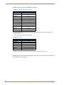
Configuration Information and Control Options
Switching Configuration Information
The configuration file stored on the CPU contains routing and control information for the AMX Enova
Routing System.
Note: The configuration file is automatically generated by the system based on its hardware – input
and output boards, expansion boards, front control panel, CPU, etc. If boards are added during
runtime, they are immediately added to the system’s configuration.
From the factory, this configuration normally contains two virtual matrices (VMs) for switching signals:
VM 0 = all signals and VM 1 = video signals. In systems like the Enova DGX Switcher, both VMs
normally route the same signals. On occasion, systems are shipped with custom programmed
configurations according to customer specifications.
Important: Embedded audio signals switch with the video channels. Through the use of Audio
Insert/Extract Boards, embedded audio can be extracted and external audio matrix switches can be
executed (using a separately purchased audio matrix switcher like the Precis DSP) and then
reinserted post-switch on the output side.
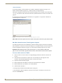
XNConnect configuration software ( can be used to customize the configuration file (see page 175).
However, unless you need to modify your system, you will not need to use XNConnect.
If you do modify the configuration file, we recommend making a copy of it first.
Configuration file modifications include creating local presets and setting the Control Panel password,
as well as adding or managing hardware. XNConnect graphically displays the Enova DGX Switcher and
its control configuration.
Board Configuration Information
DGX Configuration Software is available at www.amx.com for use with HDMI, DVI, and the DXLink
Boards. This software can be used to set the Scaler mode, the aspect ratio, and custom resolutions as well
as re-program the EDID on input boards (see page 157).
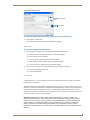
Important: Because signals routed through HDMI, DVI, and DXLink Boards in an Enova DGX
Switcher normally produce a quality image, you will not need to use DGX Configuration Software
unless the installation has special resolution or EDID requirements.
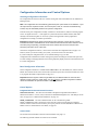
Control Options
Integrated NetLinx Central Control Processor
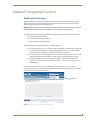
WebConsole interface – The main control method is through the integrated NetLinx Master’s
WebConsole interface. A server (LAN) connection is established through the LAN 100/1000 port on the
CPU (see page 39). For WebConsole information, see page 131.
SEND_COMMANDs – The Enova DGX Switcher can be controlled using AMX
SEND_COMMANDs. ICSP is the primary protocol for all system level messaging on integrated
NetLinx Central Control Processors and is a peer-to-peer protocol used for both Master-to-Master and
Master-to-device communications. For details, see page 151.
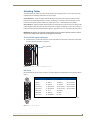
Control Panel
The Control Panel is standard on all Enova DGX Switchers (see page 111).
The following external methods of control are also available.
22
Instruction Manual – Enova DGX 8/16/32 Digital Media Switchers
Product Overview and General Specifications
AMX Control Devices
The Enova DGX Switcher is compatible with a number of AMX control devices via Native NetLinx
communication. For control programming information, see the chapter on ICSP commands on page 151
and the instruction manual for the specific AMX control device.
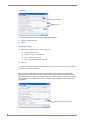
IP Control Software
Enova DGX Switchers can be controlled using the XBar (crosspoint control interface) via the device’s
WebConsole, which can be accessed through PC-based Internet browsing software. The server delivers
HTML pages for setting up the system and a Java control applet, which allows for remote control of the
Enova DGX Switcher.
BCS (Basic Control Structure) Protocol
The Enova DGX Switcher can be controlled with an external serial controller using BCS* protocol, a
command language for programming control operations and for diagnostic purposes.
Serial control (sends and receives ASCII characters)
Use the Control (RS-232 serial) port or use the USB Control port (as a virtual COM port);
both are located on the CPU
Commands can be entered into a terminal emulation program on a PC
* For information on BCS commands, see the Instruction Manual – BCS Basic Control Structure
Protocol at www.amx.com.
Third-Party Controllers
A third-party controller can be attached to an Enova DGX Switcher via the RS-232 serial port.
Third-party control is also possible via a BCS Tunnel over TCP/IP (see page 58). If using a third-party
controller, see the controller documentation for operating instructions.
XNNet Protocol
Advanced programmers who want to design their own control programs can use XNNet protocol.
The XNNet API Communication Library that supports C, Java, and Visual Basic with examples of the
XNNet protocol in use is available at www.amx.com.
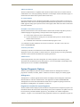
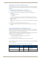
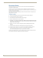
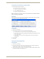
System Diagnostic Options
The three system diagnostic options for the Enova DGX Switcher are APDiagnostics software, a
programmer’s interface, and DGX _SHELL commands. The last two display in a terminal program.
APDiagnostics
APDiagnostics is a software application that monitors and displays advanced diagnostic information
about the behavior of the Enova DGX Switcher. This application is available at www.amx.com.
APDiagnostics also works with AMX Matrix Switchers that are capable of reporting such data. For
information on APDiagnostics, see Appendix C on page 187.
Programmer’s Interface for System Diagnostics
The Enova DGX Switcher displays system information in the splash screen for diagnostic purposes. The
information indicates the current status and well-being of the system components. The splash screen can
be accessed using a terminal emulation program (e.g., the Terminal view in DGX Configuration
Software – see page 173). For information on the programmer’s interface, see Appendix D on page 199.
Instruction Manual – Enova DGX 8/16/32 Digital Media Switchers
23
Product Overview and General Specifications
DGX_SHELL Commands
The Enova DGX Switcher supports a number of shell (command-line interpreter) commands for a
variety of functions, both basic and advanced (see Appendix H on page 219).
24
Instruction Manual – Enova DGX 8/16/32 Digital Media Switchers
Installation and Setup
Installation and Setup
Important: If the Enova DGX Switcher contains Epica DGX SC Optical Boards, be sure to read all of
the safety information for laser products in this chapter and in the SC Optical Board chapter.
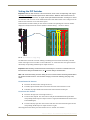
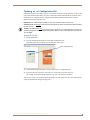
UL Safety Certifications, Notices, and Recommendations for Laser Products
Per UL requirements, make note of the following:
The DGX SC Optical Boards comply with IEC Standard: IEC 60825-1, 2001.
The boards also comply with 21 CFR 1040.10 and 1040.11 except for deviations pursuant
to Laser Notice No. 50, dated June 24, 2007.
The DGX SC Optical Output (TX) Boards are CLASS 1 LASER PRODUCTS.
The maximum output power of the laser radiation is 4.08 mW.
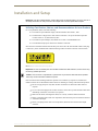
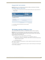
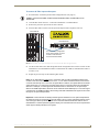
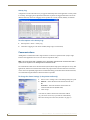
Since the class of radiation emitted from the fiber port can be Class 3R when the fiber cable or dust plug
is removed, a yellow and black label with the following caution is located on the rear of the enclosure.
FIG. 12 Caution label for Class 3R laser products
Important: No user serviceable parts are included inside Enova DGX Switchers; service should only
be done by qualified personnel.
Caution: Use of controls or adjustments or performance of procedures other than those specified
herein may result in hazardous radiation exposure.
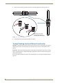
Exercise caution when installing DGX Fiber products to avoid direct eye exposure to invisible laser
radiation. Follow the recommendations below whenever installing or working with DGX Fiber products.
Be sure to apply the power only after all fiber connections are made and no fiber ends are
exposed.
Do not remove dust plugs from SC fiber connectors or the dust caps from the fiber cables until
establishing connections; avoid direct eye exposure.
Make sure all cables, including fiber cables, are correctly connected and/or terminated.
Before you unplug a fiber cable on an input board, disconnect the power on the DGX TX that is
connected to the input.
Before you unplug a fiber cable on an output board, disconnect the switch for that output
connector.
Instruction Manual – Enova DGX 8/16/32 Digital Media Switchers
25
Installation and Setup
Site Recommendations
When placing the enclosure, follow the recommendations and precautions in this section to reduce
potential installation and operation hazards.
Environment
Choose a clean, dust free, (preferably) air-conditioned location.
Avoid areas with direct sunlight, heat sources, or high levels of EMI
(Electromagnetic Interference).
Chassis Accessibility
Make sure the front and rear panels of the enclosure are accessible, so that you can monitor the Power
indicator LED on the front and the other LED indicators on the rear. Leaving adequate clearance at the
rear will also allow for easier cabling and service.
Power
Important: We recommend attaching all power cords to a surge protector (20 A) and/or an AC line
conditioner.
The source’s electrical outlet should be installed near the router, easily accessible, and properly
grounded. Power should come from a building branch circuit. We strongly recommend using a dedicated
line for the system’s power. Use a minimum breaker current rating of 20 A for 110 V or 10 A for 230 V.
To avoid an overload, note the power consumption rating of all the equipment connected to the circuit
breaker before applying power.
General Hazard Precautions
These recommendations address potential hazards that are common to all installations.
Important: DXLink twisted pair cable runs for DXLink equipment should only be run within a
common building.
Elevated Operating Temperature
The maximum rated ambient temperature for Enova DGX Switcher is 104° F (40° C).
All equipment should be installed in an environment compatible with the manufacturer’s maximum
rated ambient temperature. In a closed or multi-unit rack assembly, the operating ambient temperature of
the rack environment may be greater than the ambient room temperature.
Caution: To protect the equipment from overheating, do not operate in an area that exceeds
104° F (40° C) and follow the clearance recommendation below for adequate airflow.
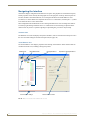
Airflow Restriction
Enova DGX Switchers are designed to adequately dissipate the heat they produce under normal
operating conditions; however, this design is defeated if high heat producing equipment is placed
directly above or below an enclosure.
Caution: To prevent overheating, avoid placing high heat producing equipment directly above or
below the enclosure. The system requires a minimum of one empty rack unit above and below
(three empty rack units are recommended). Verify that the openings on the top and sides of the
enclosure are not blocked and do not have restricted air flow.
Mechanical (Rack) Loading
When installing equipment in a rack, distribute the weight to avoid uneven mechanical loading.
Note that fully loaded, the Enova DGX 8 weighs approximately 35 pounds (15.9 kg), the Enova DGX 16
weighs approximately 55 pounds (24.95 kg), and the Enova DGX 32 weighs approximately 73 pounds
(33.1 kg).
26
Instruction Manual – Enova DGX 8/16/32 Digital Media Switchers
Installation and Setup
Circuit Overloading
When connecting the equipment to the supply circuits, be aware of the effect that overloading the
circuits might have on over-current protection and supply wiring.
Reliable Earthing (Grounding)
Reliable earthing of rack-mounted equipment should be maintained. If not using a direct connection to
the branch circuit (e.g., plugging into a power strip), pay particular attention to supply connections.
Caution: We strongly recommend attaching all of the power cords to a surge protector and/or an AC
line conditioner. After powering up the enclosure, apply power to the source and destination devices.
Unpacking
Enova DGX Switchers are shipped with one enclosure per shipping box. The invoice is sent separately;
a packing slip is attached to the outside of each box. Each box contains the following items:
Enova DGX Digital Media Switcher
Two standard US power cords (if shipped within the US)
Other enclosure related products, as needed
The documentation in the first box includes:
AMX Enova DGX 8/16/32 Digital Media Switchers Quick Start Guide
AMX Enova DGX Audio Insert/Extract Board Quick Start Guide
Control Panel Custom Label Kit (for inputs and outputs and for LCD Function menu)
For orders comprising multiple enclosures, the shipping boxes are marked as “Chassis __ of __,” where
the first blank is the box number and the second blank is the total number of boxes in the shipment.
Unpacking Tips
Before fully unpacking the enclosure, inspect the shipping box for any signs of damage.
If a box is partially crushed or any sides have been broken open, notify the shipping agency
immediately and contact your AMX representative (see the warranty at www.amx.com).
Once unpacking is complete, closely check the physical condition of the enclosure.
Collect all documentation.
Note: Please save the original shipping container and packing materials. AMX is not responsible for
damage caused by insufficient packing during return shipment to the factory. Shipping boxes are
available; contact your AMX representative for details.
Instruction Manual – Enova DGX 8/16/32 Digital Media Switchers
27
Installation and Setup
Options for System Setup with DXLink™
The following table contains seven options in an Enova DGX Switcher for using DXLink™ Input and
Output Boards in conjunction with DXLink™ Transmitters and Receivers.
Note: DXLink Modules can also be used as a standalone, end-to-end solution; see the “Instruction
Manual – DXLink™ Twisted Pair Transmitters/Receiver.”
System Setup Options – Enova DGX Boards with DXLink Modules/Wallplates
DXLink Module/Wallplate
Enova DGX Input Board
Enova DGX Output Board
DXLink Module
HDMI TX Module
DXLink Twisted Pair
DXLink Twisted Pair
HDMI RX Module
HDMI TX Modules
DXLink Twisted Pair
Any output board*
Multi-Format TX Module
DXLink Twisted Pair
DXLink Twisted Pair
Multi-Format TX Module
DXLink Twisted Pair
Any output board*
Multi-Format Wallplate TX
DXLink Twisted Pair
DXLink Twisted Pair
Multi-Format Wallplate TX
DXLink Twisted Pair
Any output board*
Decor Wallplate TX
DXLink Twisted Pair
DXLink Twisted Pair
HDMI RX Module
Decor Wallplate TX
DXLink Twisted Pair
Any output board*
HDMI RX Module
Any input board*
DXLink Twisted Pair
HDMI RX Module
Not Applicable
Not applicable
HDMI RX Module
Not applicable
HDMI RX Module
Not applicable
* If the board is an SC Optical Board it will need the appropriate DGX Fiber Module; see table below.
A typical system setup for a source and destination is shown on page 86 and has an Enova DGX 16 with
DXLink Boards used in conjunction with DXLink HDMI Transmitters and Receivers.
Caution: If you plan to connect switching systems via their DXLink ports, be sure to read the
information on page 89.
Options for System Setup with Fiber
The table below contains sixteen options in an Enova DGX Switcher for using DVI, HDMI, or DXLink
Boards with SC Optical Boards in conjunction with DGX Fiber Modules.
Note: DGX Fiber Modules can also be used as a standalone, end-to-end solution; see the
“Instruction Manual – DGX Transmitters & Receivers.”
System Setup Options – Enova DGX Boards with DGX Fiber Modules
DGX Fiber Module
Enova DGX Input Board
Enova DGX Output Board
HD-15 TX
SC Optical
DVI
Not Applicable
DVI TX
SC Optical
DVI
Not Applicable
HD-15 TX
SC Optical
HDMI
Not Applicable
DVI TX
SC Optical
HDMI
Not Applicable
HD-15 TX
SC Optical
DXLink
(requires DXLink RX)
DVI TX
SC Optical
DXLink
(requires DXLink RX)
Not Applicable
DVI
SC Optical
HD-15 RX
Not Applicable
DVI
SC Optical
DVI RX
Not Applicable
HDMI
SC Optical
HD-15 RX
Not Applicable
HDMI
SC Optical
DVI RX
DXLink
SC Optical
HD-15 RX
(requires DXLink TX)
DGX Fiber Module
DXLink
SC Optical
DVI RX
HD-15 TX
SC Optical
SC Optical
HD-15 RX
HD-15 TX
SC Optical
SC Optical
DVI RX
DVI TX
SC Optical
SC Optical
HD-15 RX
DVI TX
SC Optical
SC Optical
DVI RX
(requires DXLink TX)
A typical system setup for a source and a destination is shown on page 97 and has an Enova DGX 32
with DGX SC Optical Boards used in conjunction with DGX Fiber Modules.
28
Instruction Manual – Enova DGX 8/16/32 Digital Media Switchers
Installation and Setup
The DGX HD-15 and DGX DVI Transmitter Modules can be installed interchangeably. The
DGX HD-15 and DGX DVI Receiver Modules are interchangeable as well, providing for an
extremely flexible system. For example, in the same system, a source device can send a DVI signal
and the destination device(s) can receive an RGBHV signal.
Note: In addition to the system setup options listed in the table above, optical signal flow between
Enova DGX Switcher and Epica DGX 16/32/144 enclosures (from SC fiber connector to SC fiber
connector) is supported. Contact your AMX representative for these and other system design
possibilities.
Rack Installation and System Setup
Enova DGX Switchers can be mounted in a standard EIA 19 in. (48.26 cm) rack.
Required Items for Rack Installation:
Enclosure
Standard EIA 19 in. (48.26 cm) rack
Screwdriver
Screws that fit your rack for mounting the enclosure
Power cords (2)
Surge-protector – highly recommended
Optional Items for Rack Installation:
A PC or laptop computer with a null modem cable for communication with the enclosure via
the RS-232 serial (Control) port
Installation Recommendations:
Write the serial numbers (normally located on rear of enclosure) in an easily accessible
location before installing the enclosure in a rack.
Use an earth-grounded power cord / system with an Enova DGX Switcher.
Attach all power cords to a single surge protector and/or an AC line conditioner.
Apply power to the Enova DGX Switcher before applying power to its source and destination
devices.
Safety Recommendations for Laser Products
Important: No user serviceable parts are included inside Enova DGX Switchers; service should only
be done by qualified personnel.
Caution - Use of controls or adjustments or performance of procedures other than those specified
herein may result in hazardous radiation exposure.
Exercise caution when installing DGX Fiber products to avoid direct eye exposure to invisible laser
radiation. Follow the recommendations below whenever installing or working with DGX Fiber products.
Be sure to apply the power only after all the fiber connections are made and no fiber ends are
exposed.
Do not remove dust plugs from SC fiber connectors or the dust caps from the fiber cables until
establishing connections; avoid direct eye exposure.
Make sure all cables, including fiber cables, are correctly connected and/or terminated.
Before you unplug a fiber cable on an input board, disconnect the power on the DGX TX that
is connected to the input.
Before you unplug a fiber cable on an output board, disconnect the switch for that output
connector.
Instruction Manual – Enova DGX 8/16/32 Digital Media Switchers
29
Installation and Setup
Installation Procedure
A flow chart showing the installation sequence is in FIG. 13. The procedure on the following page
provides general steps with references to detailed information found in later sections of the manual.
Install in rack.
If applicable - remove Audio Boards, set DIP switches
to insert or extract, and re-install in enclosure.
If applicable - attach cable management
bars for SC Optical Boards.
Attach first two video input and output cables.
If applicable, install DXLink and/or DGX Fiber TXs and RXs.
If applicable, wire first two connectors on audio board(s).
Apply power to enclosure(s)
and then to system devices.
Important: If the system contains
Audio Insert/Extract Boards, they
must be removed from the system
and the DIP switches on the boards
must be set to either insert or extract
audio according to the system’s
requirements (see page 101).
Important: DXLink twisted pair cable
runs for DXLink Input and Output
Boards should only be run within a
common building.
Connect Program port to PC’s COM port.
Establish TCP/IP connection from integrated Master to LAN.
Configure system via NetLinx Studio.
Execute a test switch.
Attach remaining video input and output cables.
If applicable, install remaining DXLink and/or DGX Fiber TXs and RXs.
If applicable, wire remaining connectors on audio board(s).
FIG. 13 Flow chart for installation procedure
Caution: To prevent overheating and airflow restriction, avoid placing high heat producing
equipment directly above or below the enclosure. The system requires a minimum of one empty rack
unit above and below (three empty rack units are recommended). Verify that the openings on the top
and sides of the enclosure are not blocked and do not have restricted air flow.
Note: If desired, remove rubber feet from bottom of enclosure before rack installation.
To install and setup an Enova DGX Switcher:
Important: Installation of the Enova DGX 32 requires a minimum of two people for Step 2; we
recommend using three people.
1.
Select a position in the rack for the enclosure that is accessible and does not restrict airflow
(see Caution above).
2.
Position the enclosure in the rack. Screw in the rack ear screws on each side.
FIG. 14 Rack mounting screws aligned with rack
30
Instruction Manual – Enova DGX 8/16/32 Digital Media Switchers
Installation and Setup
3.
Audio Insert/Extract Boards only – Remove the boards (see page 105) and set the DIP switches to
either insert or extract audio (see page 105). This is the only mechanism for configuring the insert/
extract functionality.
Caution: On systems with SC fiber connectors, we recommend using the provided cable
management bars or some other type of cable management system to avoid damage to the fiber
cables.
4.
Recommended for SC Optical – Attach the provided cable management bars to the input and output
boards (see page 32).
5.
Attach only the first two source and destination devices.
If connecting devices to HDMI or DVI Boards, see the special information for these boards
below.
If connecting devices to DXLink Boards, the boards require DXLink HDMI Transmitters and
Receivers. Install the Transmitters and Receivers between the first two source and destination
devices and the DXLink Boards (see “System Setup with DXLink™ Transmitters and
Receivers” on page 82 and the product’s documentation).
If connecting devices to SC Optical Boards, the boards require DGX Fiber Modules. Install
the modules between the first two source and/or destination devices and the SC Optical
Boards (see “System Setup with DGX Fiber Modules” on page 97 and the modules’
documentation).
If wiring devices to an Audio Insert/Extract Board(s), see page 101.
6.
Attach power cords to both power receptacles on the enclosure, then turn on the entire system
(see page 35).* We recommend using a surge protector and/or an AC line conditioner.
7.
Set up the system using the integrated NetLinx Master (see page 39):
8.
Disconnect the factory default switch and execute a test switch to make sure the system is working
properly (see page 49).
9.
When the test switch works correctly, attach the remaining source and destination devices and any
additional DXLink HDMI or DGX Fiber Transmitters and Receivers. If applicable, wire remaining
connectors on the Audio Insert/Extract Board(s).
* Power Budget Planning – If the system contains DXLink Boards, be sure to read the section on Power
Budget Planning on page 88. The power draw for the system should be calculated in order to maintain
the power redundancy of the power supplies in the enclosure. Calculating the power draw also helps
determine how many DXLink Transmitters and Receivers can be powered via the switcher.
Special Information for HDMI and DVI Boards
If the system contains HDMI and/or DVI Boards, configuration of the boards may be necessary.
DGX Configuration Software is available for configuring the boards (see page 157). This software is
available at www.amx.com.
Special Information for the Audio Insert/Extract Board
If the system contains Audio Insert/Extract Boards, the connector default settings may need to be
changed for insertion and extraction of audio, see page 105.
Instruction Manual – Enova DGX 8/16/32 Digital Media Switchers
31
Installation and Setup
Installation Options
Additional installation tasks may include the following:.
Establishing external serial control (DB-9 port) – see page 53.
Establishing external serial control (USB virtual COM port) – see page 54.
CPU backup with Micro SD memory card – see page 59.
Setting the Control Panel password – see page 126.
Defining local presets – see page 182.
Defining global presets – see page 119.
Attaching Cable Management Bars
If the enclosure has Epica DGX SC Optical Input and Output Boards installed, cable management bars
are provided.
Caution: Do not severely bend or kink the SC fiber cable. Irreversible damage can occur. Refer to
the physical limitations (bend radius) specified for the cable by the manufacturer. The bend radius
for AMX SC terminated fiber cables is 2 inches (5 cm).
To install cable management bars:
1.
Enova DGX 32 only – Loosen the two captive screws that hold the connector numbering plate at
the top of the connectors. Remove the connector numbering plate and set aside.
Connector numbering plate
FIG. 15 Connector numbering plate on Enova DGX 32
2.
Align the two screw holes on the end of the cable management bar with the two screw holes on the
end of the board. (Note the position of the long part of the bar in relation to screw holes.)
Fasten cable management bar
with two screws on one end
and one on the other end
Tie cable to cable management
bar far enough from connector
to allow for manufacturer’s
recommended bend radius
Enova DGX 32
Input board
Enova DGX 8/16
Important: Do not over
tighten installation screws.
Output board
Note: On the Enova DGX 8/16, the orientation of the cable
management bar is reversed from the input to the output board.
FIG. 16 Installation of cable management bars
32
Instruction Manual – Enova DGX 8/16/32 Digital Media Switchers
Installation and Setup
3.
Insert and tighten the two screws at the end of the cable management bar (do not over tighten the
screws).
4.
Align, insert, and tighten the single screw at the other end of the cable management bar (do not over
tighten).
5.
Tie the cable to the cable management bar far enough from the connector to allow for the
manufacturer’s recommended bend radius.
Note: The bend radius for AMX SC terminated fiber cables is 2 inches (5 cm).
6.
Enova DGX 32 only – Replace the connector numbering plate that was removed in Step 1.
Attaching Video Input and Output Cables
Input and output connectors are the attachment points for source and destination devices that connect to
the system. Viewed from the rear of the enclosure, the input boards (for attaching sources) are on the left,
and the output boards (for attaching destinations) are on the right.
Enova DGX 8 – Enclosures have 4 horizontal board slots (2 slots each for the input and the
output boards, with 4 connectors per board), allowing for a maximum configuration of 8x8.
Enova DGX 16 – Enclosures have 8 horizontal board slots (4 slots each for the input and the
output boards, with 4 connectors per board), allowing for a maximum configuration of 16x16
(FIG. 17).
Enova DGX 32 – Enclosures have 16 vertical board slots (8 slots each for the input and the
output boards, with 4 connectors per board), allowing for a maximum configuration of 32x32
(FIG. 18).
Connectors and Input and Output Channels
Enova DGX 8/16 – Input and output channel numbers correspond to the connectors and are
located between the input and output boards. For inputs, numbering is consecutive from left to
right on each board from the top board to the bottom one; outputs start over at “1” and follow
the same pattern.
Enova DGX 32 – Input and output channel numbers correspond to the connectors and are
located on the numbering plate (metal strip) directly above the boards. For inputs, numbering
is consecutive from top to bottom on each board from the left board to right one; outputs start
over at “1” and follow the same pattern
Input connectors
Output connectors
Numbering plate
FIG. 17 Numbering indicates input and output channels (Enova DGX 16 shown)
Instruction Manual – Enova DGX 8/16/32 Digital Media Switchers
33
Installation and Setup
Numbering plate
<-Input connectors->
<-Output connectors->
FIG. 18 Numbers on numbering plate indicate input and output board channels (Enova DGX 32 shown)
For information on board connectors and cabling and specifications for specific types of connectors:
HDMI Boards – see page 63
DVI Boards – see page 73
DXLink Twisted Pair Boards – see page 79
DGX SC Optical Boards – see page 95
Input and Output Signal Cables
Caution: If you are connecting switching systems via their DXLink ports, be sure to read the
information on page 89.
If using cable management bars, install them before attaching the cables (see page 32).
Before connecting all of the input and output cables and wires, attach only the ones for the first two
sources and destinations (and any applicable DXLink or DGX Fiber Transmitters and Receivers).
Complete the remaining installation tasks (applying power and any system setup though NetLinx Studio),
and then disconnect the factory default switch and execute a test switch (see page 49). When the test
switch is successful, attach the remaining input and output cables and wires.
34
Instruction Manual – Enova DGX 8/16/32 Digital Media Switchers
Installation and Setup
Attaching Audio Input and Output Wires
Enova DGX Switchers can be ordered to include an Audio Insert/Extract Board(s). This audio board
works in conjunction with HDMI, DVI, and DXLink Boards. The inputs and outputs are configured on a
per connector basis to insert or extract audio.
Important: Setting the DIP switches is the only mechanism for configuring the Audio Insert/Extract
Board’s insert/extract functionality. Therefore, setting the switches (which requires removal of the
board from the enclosure) needs to be done at the time of installation setup.
For specifications, connector wiring, and configuration information, see the “Audio Insert/Extract
Board” chapter on page 101.
Audio Insert/Extract Boards
FIG. 19 Audio Insert/Extract Boards in an Enova DGX 32
Applying Power and Startup
The enclosure’s universal power receptacles will accept all major international standard power sources.
Two US power cords are included with all shipments unless ordered otherwise. Maximum power
specifications are on each power receptacle (and are also listed on page 20). Always use earth-grounded
power cords / system with an Enova DGX Switcher.
The source electrical outlet should be installed near the enclosure, easily accessible, and properly
grounded. Power should come from a building branch circuit. We strongly recommend using a dedicated
line for the system’s power. Use a minimum breaker current rating of 20 A for 110 V or 10 A for 230 V.
To avoid an overload, note the power consumption rating of all the equipment connected to the circuit
breaker before applying power.
Power Budget Planning for Systems with DXLink Boards
If the system contains DXLink Boards, be sure to read the section on Power Budget Planning on
page 88. The power draw for the system should be calculated in order to maintain the power redundancy
of the power supplies in the enclosure. Calculating the power draw also helps determines how many
DXLink Transmitters and Receivers can be powered via the switcher.
Complete Power Redundancy Setup
For proper redundant operations, both power supplies must be powered at all times. To take full
advantage of the dual power feeds and redundant power supplies on the Enova DGX Switcher, we
recommend cabling the primary Enova DGX Switcher power feed, via a power strip to an outlet
connected to one circuit breaker and the redundant power feed via a power strip to an outlet connected to
a second circuit breaker.
Instruction Manual – Enova DGX 8/16/32 Digital Media Switchers
35
Installation and Setup
FIG. 20 Power setup for complete redundancy on Enova DGX 32
Caution: We recommend attaching all power cords to a surge protector and/or an AC line
conditioner.
Power-Up Sequence
The following instructions start with attaching only two source and destination devices for the purpose
of executing a test switch (after the factory default switch is disconnected).
To apply power:
1.
Attach the first two source and destination devices.
Do not apply power to the source and destination devices until Step 7.
If connecting devices to DXLink Boards, the boards require DXLink HDMI Transmitters and
Receivers. Install the Transmitters and Receivers between the first two source and/or
destination devices and the DXLink Boards (see “System Setup with DXLink™ Transmitters
and Receivers” on page 82 and the product’s documentation).
If connecting devices to SC Optical Boards, the boards require DGX Fiber Modules. Install
the modules for the first two source and/or destination devices and then connect the modules
to the SC Optical Boards (see “System Setup with DGX Fiber Modules” on page 97 and the
module’s documentation).
2.
36
Optional – Attach an external control device/system (see page 52).
Instruction Manual – Enova DGX 8/16/32 Digital Media Switchers
Installation and Setup
3.
Plug power cords into both of the power receptacles on the enclosure.
Enova DGX 8/16 power supplies
FIG. 21 Attach power cables to both power receptacles (Enova DGX 8/16 shown)
Enova DGX 32 power supplies
FIG. 22 Attach power cables to both power receptacles (Enova DGX 32 shown)
4.
Plug the other end of each power cord into a power strip(s) that is turned off (we recommend using a
20 A circuit breaker on a 110 circuit for fully loaded enclosures).
5.
Turn on the power strip and wait 30 seconds.
The Power indicator LED on the Control Panel illuminates green (showing that both redundant power
supplies are working). If only one power supply is working, the Power indicator will illuminate a
constant red (check power connections and switches).
The LCD on the Control Panel illuminates and displays the menu screen.
6.
Optional – Apply power to a control device/system.
7.
For systems with SC Optical Boards – Apply power to the DGX TX and RX Fiber Modules.
8.
Apply power to the source and destination devices.
9.
Disconnect the factory default switch and execute a test switch (see page 49).
10. Attach the remaining sources and destinations and apply power to them.
Important: Whenever the system is powered down, be sure the indicator LEDs on the CPU are off
and the fans have stopped before reapplying power.
Instruction Manual – Enova DGX 8/16/32 Digital Media Switchers
37
Installation and Setup
Indicator Lights at Startup
When the enclosure powers up, the indicator LEDs respond as follows:
Enova DGX LED Indicators
LED
Front
Rear –
Power
Supplies
Normal Display
Power
System power status
Constant green
AC Power
AC power present
Constant green
DC Power
(Tri-color LED)
Status
Rear –
CPU
Indicates
• DC power present
Cautionary
Constant red: only
one power supply is
working
Not illuminated:
AC failure
Not illuminated:
DC failure
• Fault Status
Amber: power
supply is over
temperature
System status
Red: power supply is
in a fault state
Blinking red/green:
an exception has
been logged in IOS
(validation failure)
• Power supply temperature Constant green
Constant green during power
up, then blinking green at 1
second on/off intervals
Blinking red: dropped
into IOS mode*
LAN 100/1000
• L/A
• Cables are connected and
terminated correctly
• Constant green
• SPD
• Receiving or transmitting
LAN data packets
• Blinks yellow
* IOS (Initial Operating System) is the base layer operating system on Enova DGX Switcher equipment. IOS
performs functions such as hosting higher level run-time software applications. If unexpected critical errors are
encountered within such hosted applications, system control of the equipment may be passed to the IOS layer
preventing normal system operation until the error is manually cleared. Report all such errors to technical support
(see page 62).
Important: If the indicator LEDs do not respond with a normal display as stated above, check power
connections, before contacting technical support (see page 62).
Redundant Power Supply (RPS)
Every enclosure ships with two mutually-redundant (hot-swappable) power supplies.
The Power indicator on the front of the enclosure illuminates a constant red if a problem occurs with one
of the power supplies. Check the AC and DC LED indicators on the left of each power receptacle to
determine if a power supply is not working. For additional LED information, see above.
Important: A failed power supply should be replaced as soon as possible to maintain the system’s
power redundancy. For replacement information, contact technical support (see page 62).
Power Supply Troubleshooting
If a power supply’s AC and DC power indicator LEDs are not illuminated: Check to
be sure the power cord is completely plugged into the enclosure and the power source.
If a power supply’s DC LED illuminates amber or red, contact technical support
(see page 62).
Caution: Do not remove a failed power supply until the replacement is ready to install, unless
directed to do so by technical support.
38
Instruction Manual – Enova DGX 8/16/32 Digital Media Switchers
Installation and Setup
System Setup for Using the Integrated NetLinx Master
The Enova DGX Switcher has an integrated NetLinx Central Control Processor (Master) that establishes
its LAN (Local Area Network) connection through the LAN 100/1000 port on the CPU. The Master
provides a WebConsole interface that allows you to make various configuration settings via a web
browser on any PC connected to the same LAN.
The NetLinx Master’s WebConsole delivers HTML pages for setting up the system plus the XBar
Controller (a Java control applet), which allows for remote control of an Enova DGX Switcher using
PC-based Internet browsing software.
Important: The Enova DGX Switcher uses DHCP to retrieve its IP address by default.
The enclosure must be connected to a LAN in order to get an IP address from a DHCP server. After the
network assigns a DHCP IP address, a static IP address can be assigned in its place.
Important: Although it is also possible to provide access from outside a LAN via the Internet,
security issues for your LAN environment must be taken into account (contact your Network
Administrator).
System Setup Overview
Important: The Enova DGX Switcher uses DHCP by default.
The Program (serial USB) port and LAN 100/1000 (Ethernet) port each play a role in conjunction with
the integrated Master.
Program port – used during the initial setup to obtain the IP address from the integrated
Master. This port is connected to a PC running NetLinx Studio.
LAN 100/1000 port – provides functionality for the following protocols: FTP, SSH, Telnet,
HTTP, HTTPS/SSL, and ICSP (for protocol descriptions and standard port numbers used, see
the table on page 43). This port is connected to a LAN.
The system setup example below for using the integrated NetLinx Master shows an Enova DGX 32
Digital Media Switcher connected to a LAN via the LAN 100/1000 port. Both computers in the
illustration have access to the enclosure via the LAN. The PC on the right has established
communication via the Program port on the Enova DGX 32 and is running NetLinx Studio to obtain the
IP address for the integrated Master.
Caution: Be careful not to create a network (Ethernet) loop. To avoid doing so, see page 89.
Program port connected to PC running NetLinx Studio
FIG. 23 Enova DGX 32 connected via a LAN to two PCs (Program port is connected for initial set up)
Instruction Manual – Enova DGX 8/16/32 Digital Media Switchers
39
Installation and Setup
Program Port and LAN 100/1000 Port
Since the Program port and the LAN 100/1000 port are used in conjunction with each other for NetLinx
system setup, information for cable requirements, LEDs, etc. on each port is given before the setup
information.
Program Port
The Enova DGX Switcher’s integrated NetLinx Master is equipped with a low-speed USB connection
labeled “Program.” Use the provided USB mini-AB adapter cable (CA1090-541) to establish a
connection between the Program port on the enclosure and the PC’s USB port. This connection provides
serial-based communication between the integrated Master and NetLinx Studio. This port is useful for
getting and setting the system’s IP address (in NetLinx Studio, open Telnet and enter either GET IP
<D:P:S> or SET IP <D:P:S>, where D:P:S is Device:Port:System).
Important: The Program port is not recommended for firmware updates or large file transfers.
These more data-intensive operations are better handled via the LAN 100/1000 port connection.
Cable Requirements
USB mini-AB adapter cable (provided) – required to connect an Enova DGX Switcher via its
Program port to a PC.
Program Port LEDs – Modes and LED Blink Patterns
Program port LEDs
Program port
FIG. 24 Program Port LEDs
The following table lists the modes and the blink patterns for the Program port’s LED indicators which
are associated with each mode. These blink patterns are not evident until the unit is powered.
Modes and LED Blink Patterns
LEDs and Blink Patterns
Status
(Green)
Output
(Red)
Input
(Yellow)
On
Mode
Description
OS Start
Starting the operating system (OS).
On
On
Boot
Integrated Master is booting.
On
Off
On
Contacting DHCP
Server
Integrated Master is contacting a DHCP
server for IP configuration information.
On
Off
Fast Blink
Unknown DHCP
Server
Integrated Master could not find the DHCP
server.
Fast Blink
Off
Off
Downloading Boot
Firmware
Downloading Boot firmware to the integrated
Master’s flash memory.
Do not cycle power during this process.
Fast Blink
Fast Blink
Fast Blink
No program running
Either no program is loaded or the program is
disabled.
On
Normal*
Normal*
Normal
Integrated Master is functioning normally.
1 blink per
second
On
indicates
activity
On
indicates
activity
* Normal is typically off. However, this state may change depending on external inputs.
40
Instruction Manual – Enova DGX 8/16/32 Digital Media Switchers
Installation and Setup
LAN 100/1000 Port
The LAN 100/1000 (Ethernet) port, which provides the connection from the integrated NetLinx Master
to a LAN, is located on the rear of the enclosure on the right-hand side of the CPU.
Important: Because the LAN 100/1000 port is the single, shared connection to the LAN for all
connected DXLInk Transmitters and Receivers, if the LAN port on the Transmitters and Receivers
will be used for network connectivity, a Gigabit (1000 Mbps) LAN connection between the network
and the Enova DGX Switcher’s LAN port is strongly recommended. Lower speed connections may
result in inferior performance of the embedded Ethernet network.
Important: The two RJ-45 connectors at the far left of the CPU should only be used to connect
autonomous devices (to prevent network loops); do not attempt to use either of them for a TCP/IP
connection or to link enclosures.
Cable Requirements and Pinouts
RJ-45 link cable (either crossover or straight-through) – required to connect an
Enova DGX Switcher to a LAN.
Note: Cable can be wired to either T568A (see below) or T568B (on the next page), as long as the
wiring is consistent on both ends.
T568A
The following table lists the pinouts, signals, and pairing for the Ethernet connector when wired for
straight-through cable according to T568A.
T568A Pairing
T568A
Pin
Connections
Pairing
1
TX+
Signals
1 --------1
1 --------2
Color
2
TX-
2 --------2
3
RX+
3 --------3
4
No connection
4 --------4
Blue
5
No connection
5 --------5
Blue - White
6
RX-
6 --------6
Orange
7
No connection
7 --------7
Brown - White
8
No connection
8 --------8
Brown
Green - White
Green
3 --------6
Orange - White
FIG. 25 shows the connections for Ethernet RJ-45 connector/cable per T568A.
FIG. 25 RJ-45 connections per T568A
Instruction Manual – Enova DGX 8/16/32 Digital Media Switchers
41
Installation and Setup
T568B
The following table lists the pinouts, signals, and pairing for the Ethernet connector when wired for
straight-through cable according to T568B.
T568B Pairing
T568B
Pin
Connections
Pairing
Color
1
TX+
Signals
1 --------1
1 --------2
Orange - White
2
TX-
2 --------2
3
RX+
3 --------3
Orange
3 --------6
Green - White
4
No connection
4 --------4
Blue
5
No connection
5 --------5
Blue - White
6
RX-
6 --------6
Green
7
No connection
7 --------7
Brown - White
8
No connection
8 --------8
Brown
FIG. 26 shows the connections for Ethernet RJ-45 connector/cable per T568B.
FIG. 26 RJ-45 connections per T568B
LAN 100/1000
Indicator LEDs
LAN 100/1000 Indicator LEDs
L/A (green) LED
SPD (yellow) LED
LAN 100/1000 port
FIG. 27 LAN 100/1000 port and LED indicators
42
Instruction Manual – Enova DGX 8/16/32 Digital Media Switchers
Installation and Setup
The LAN 100/1000 (RJ-45) port is an Ethernet link connector, handling Ethernet 10/100/1000
connections for 1000 Mbps (megabits per second), 100 Mbps, and 10 Mbps. This connection is
compatible with most Ethernet based LANs.
Important: Because the LAN 100/1000 port is the single, shared connection to the LAN for all
connected DXLInk Transmitters and Receivers, if the LAN port on the Transmitters and Receivers
will be used for network connectivity, a Gigabit (1000 Mbps) LAN connection between the network
and the Enova DGX Switcher’s LAN port is strongly recommended. Lower speed connections may
result in inferior performance of the embedded Ethernet network.
The two small rectangular LEDs on the RJ-45 connector indicate the following:
Green L/A LED
On – Link is active (when the Ethernet cable is connected and terminated correctly)
Yellow SPD LED
On – receiving or transmitting LAN data packets
IP Protocols Used by the Integrated Controller
IP Protocols Used by the Integrated Controller
Protocol
Description
Standard Port #
FTP
The integrated Master has a built-in FTP server
21/20 (TCP)
SSH
22 (TCP)
The SSH port functions using the same interface as Telnet but over a
secure shell where it uses SSL as a mechanism to configure and diagnose
a NetLinx system. This port value is used for secure Telnet communication.
Note: Only SSH version 2 is supported.
Telnet
23 (TCP)
The NetLinx Telnet server provides a mechanism to configure and
diagnose a NetLinx system.
For maximum flexibility, the Master can be configured to use a different port
than 23 or disable Telnet completely from either Telnet or the Program port
on the rear of the Enova DGX Switcher. Once disabled, the only way to
enable Telnet again is from the Program port.
HTTP
The integrated Master has a built-in web server that complies with the
HTTP 1.0 specification and supports all of the required features of
HTTP v1.1. This port is used for unsecured HTTP Internet communication
between the web browser’s UI and the integrated Master.
80 (TCP)
HTTPS/
SSL
This port is used by a web browser for secure communication between the
web server UI and the integrated Master. This port is also used for
simultaneous encryption of this data, using the SSL certificate information
on the Master as a key.
443 (TCP)
ICSP
The port is used for peer-to-peer protocol for both Master-to-Master and
Master-to-device communications.
For maximum flexibility the Master can be configured to use a different port
than 1319 or disable the ICSP over Ethernet completely from either Telnet
or the Program port on the rear of the Enova DGX Switcher. This type of
communication is used by various AMX products for communication
among themselves (see page 151).
1319 (UDP/TCP)
Instruction Manual – Enova DGX 8/16/32 Digital Media Switchers
43
Installation and Setup
System Setup via NetLinx Studio
System Requirements
Minimum web browser requirements – Microsoft Internet Explorer 7.0 or higher, Mozilla
Firefox 3.6.8 or higher, or any other web browser compatible with these browsers
JRE v1.4.x or greater – Java Plug-in for the XBar Controller
Setting up the system to use NetLinx Studio’s WebConsole requires completing all of the following
items. Detailed instructions for each item are given.
Connect the Program port to a PC and create a virtual COM port
Connect the LAN 100/1000 port to a LAN (Local Area Network)
Open NetLinx Studio on the PC*
Determine the integrated Master’s IP address via zeroconf (zero configuration
IP networking)
Change the COM setting for the LAN connection to TCP/IP
Test the connection / open the WebConsole interface
* The PC must be on the same LAN that the enclosure is connected to via the LAN 100/1000 port.
To connect to a PC via the Program port (and create a virtual COM port for it):
1. Complete the installation of the Enova DGX Switcher (see page 30) including power up of the
system.
2.
Insert the USB mini-B connector on the end of the provided USB mini-AB adapter cable into the
Program port on the rear of the Enova DGX enclosure.
Important: Before the Program port can be used for communication, the appropriate FTDI driver
used to create the virtual COM port must be installed on the PC per Step 3. At www.amx.com, a link
for this driver can be found on the product’s web page, on the right under “Application Files.”
3.
Connect the other end of the USB adapter cable to the PC. Either allow Windows® to install the
driver automatically (internet connection required) or point the installer to the location where you
have previously saved the driver. Either way will create a new
PC COM Port Serial
virtual COM port on the PC.
4.
Edit the Serial Communication settings in NetLinx Studio to
use the virtual COM port created in Step 3, and set the
communication parameters to match those in the table to the
right (be sure that the PC’s COM port and terminal program’s
communication settings also match those in the table).
Communication Settings
Baud Rate
Data Bits
Parity
Stop Bits
Flow Control
115200
8
None
1
None
Caution: Be careful not to create a network (Ethernet) loop. To avoid doing so, see page 89.
A DHCP capable server must be in the network that the Enova DGX Switcher is being connected to.
44
Instruction Manual – Enova DGX 8/16/32 Digital Media Switchers
Installation and Setup
To connect an Enova DGX to a LAN via the LAN 100/1000 port:
Important: In order to use the NetLinx WebConsole, the Enova DGX Switcher must establish an
active connection to a LAN. Do not connect the LAN 100/1000 port on the Enova DGX Switcher to a
PC; it will not work.
1.
Insert one end of the RJ-45 link cable into the LAN 100/1000 port on the enclosure.
2.
Connect the other end of the RJ-45 link cable to a LAN hub or switch. The network automatically
assigns a DHCP IP address (the assigned IP address can be changed to a static IP address).
Cable to LAN hub or switch
LAN 100/1000 (RJ-45) connector
FIG. 28 RJ-45 link cable connected to LAN 100/1000 port
3.
Check the indicator LEDs for the LAN 100/1000 connector (FIG. 27 on page 42).
Note: When the connection is made, the DHCP server on the network will automatically assign an
IP address. If you power down and power back up, the DHCP server will reassign the IP address,
which may or may not be the same address it assigned before. To prevent the possibility of the
IP address changing at power up, you can change the DHCP address to a static IP address
(complete all of the NetLinx system setup instructions first and then see page 134).
Determining the Master’s IP Address via Zeroconf in NetLinx Studio
Zero configuration (or zeroconf) technology provides a general method to discover services on a local
area network. In essence, it allows you to set up a network without any configuration. NetLinx Studio
version 3.0 (or higher) features a “Zero-Config” tab in the Workspace window. This tab provides
zeroconf networking functionality within NetLinx Studio.
The Enova DGX Switcher features a built-in zeroconf networking client that allows NetLinx Studio to
determine the unit’s DHCP IP address assigned by the network. This address can then be used to open
the WebConsole interface.
To determine the IP address of the integrated Master by accessing zeroconf:
1.
Open NetLinx Studio (v3.0 or higher) on the PC. NetLinx startup takes approximately 3 minutes.
2.
In NetLinx Studio, left-click the Zero-Config tab on the Workspace Bar to open the tab.
Tip: Right-click anywhere in the
Zero-Config space to open the
context menu and select Refresh
Zero-Config List to generate an
initial listing of all zeroconf
devices that have been detected.
IP address for WebConsole interface
Zero-Config tab
Note: Refer to the NetLinx Studio
online help for details on using
zeroconf.
FIG. 29 NetLinx Studio showing the Zero-Config tab and the IP address for a WebConsole interface
Instruction Manual – Enova DGX 8/16/32 Digital Media Switchers
45
Installation and Setup
Note: If you are not using NetLinx Studio and/or are using a third-party controller, contact your Network
Administrator for the IP address.
To change the settings to communicate via the LAN 100/1000 port:
1.
From the Settings menu, select Master Communication Settings.
The Master Communication Settings dialog box opens.
2.
From the Available System(s) list on the left, select the system.
3.
Click Communications Settings.
The Communication Settings dialog box opens.
4.
Under Platform Selection, check to be sure NetLinx Master is selected (default).
5.
Under Transport Connection Option, select TCP/IP.
A List of Addresses section opens at the bottom of the dialog box. The list contains a series of
previously entered IP Addresses/URLsand their associated names, all of which are stored within
NetLinx Studio and are user-editable).
TCP/IP
Enova DGX 16
46
Instruction Manual – Enova DGX 8/16/32 Digital Media Switchers
Installation and Setup
6.
Click New.
The New TCP/IP Setting dialog box opens.
7.
Enter the TCP/IP address and an associated description for the connection and verify port number.
Verify that the Automatically Ping . . . option is selected to make sure the Master is initially
responding online before establishing full communication.
If authentication is required for connecting to the Master at this address, enter a previously
configured user name and password (with sufficient rights).
8.
Click OK to close and return to previous dialog box.
9.
Select the new entry within the List of Addresses section.
10. Click Select to make the new entry the currently used IP Address communication parameter.
11. Click OK to save the newly entered information and close the dialog box.
12. In the Master Communication Settings dialog box, click OK to begin the communication process to
the Master (and close the dialog box).
If you are currently connected to the Master, a popup asks whether you would want to stop
communication to the Master and apply the new settings.
Click Yes to interrupt the current communication from the Master and apply the new settings.
13. Click the OnLine Tree tab in the Workspace window to view the devices on the system. The default
System value is one (1).
14. Right-click the associated System number and select Refresh System OnLine Tree. This establishes
a new connection to the specified system and populates the list with devices on that system. The
communication method is then highlighted in green at the bottom of the NetLinx Studio window.
Troubleshooting the
Connection
Troubleshooting the Connection
If the connection fails to establish, a Connection Failed dialog box appears.
Try selecting a different IP Address.
Click Retry to reconnect using the same communication parameters.
Click Change to alter your communication parameters and repeat the steps above.
Important: The PC must be on the same subnet (e.g., 192.168.X.X) as the enclosure for the
following procedure.
Instruction Manual – Enova DGX 8/16/32 Digital Media Switchers
47
Installation and Setup
To test the connection / open the WebConsole interface:
1.
Right-click on the IP address for the Enova DGX Switcher.
Select to open
via Default Browser
2.
From the context sensitive menu, select Launch Web Control Page via Default Browser.
Tip: To access the WebConsole interface after initial setup, simply type the IP address In the
address bar of the browser and press Enter.
If the WebConsole interface does not open, see the “NetLinx WebConsole Troubleshooting” below.
WebConsole Related Topics
The “NetLinx Integrated Control” chapter covers information on settings for using DHCP and
static IP address for the WebConsole (see page 131).
The “Enova DGX WebConsole Interface” chapter contains information for using the XBar
Controller, a graphic interface control panel with crosspoints for executing and disconnecting
switches (see page 137).
The “Firmware Upgrade & Info for Network Admin” chapter covers the topics of upgrading
the firmware, embedding the XBar applet, and changing the proxy setting (see page 145).
Complete information for the integrated NetLinx Master (NI-3100 Class Controller) is
documented in the WebConsole & Programming Guide – NetLinx Integrated Controllers at
www.amx.com.
NetLinx WebConsole Troubleshooting
Check the following:
All power, signal, and link connections on all of the equipment.
LED indicators for the LAN 100/1000 connector on the rear of the Enova DGX Switcher.
If the LED indicators are not illuminated, check the cable type to make sure it meets cable
requirements (see page 41).
Ping the system, i.e., at the DOS prompt enter: ping XXX.XXX.XXX.XXX
(where XXX.XXX.XXX.XXX is the WebConsole interface IP address).
Try the following:
Try connecting to the WebConsole interface again.
If the WebConsole interface still does not open, you may need to add an exception in the Proxy
Setting dialog box (see page 149).
If problems persist, contact technical support (see page 62).
48
Instruction Manual – Enova DGX 8/16/32 Digital Media Switchers
Installation and Setup
Executing a Test Switch
For new system installations, we recommend executing a test switch to verify the system is working
correctly before attaching all inputs and outputs. You must first disconnect the factory default switch of
Input 1 routed to all outputs on Virtual Matrix 1 (Level 1).
You can disconnect the factory default switch and execute a test switch from one (or more) of the
following:
NetLinx Central Control Processor (Master)
XBar Controller (NetLinx WebConsole via TCP/IP)
Control Panel
BCS (Basic Control Structure) commands over an external controller
An external third-party controller (see product directions)
Before executing the test switch:
Disconnect the factory default switch and make sure the first two source devices and the first
two destination devices are connected to the input and output connectors (for specific board
connector information and specifications, see the board chapter in this manual).
Any applicable DGX DXLink Modules / Wallplates or DGX Fiber Modules must also be
installed (see the product’s documentation).
Power must be applied to the enclosure and then to the source and destination devices.
When executing a test switch, we suggest routing Input (source) 1 to Output (destination) 2 on the
default virtual matrix of VM 0, unless you know the system was ordered with custom VMs.
After the test switch has executed successfully:
If necessary, adjust the image with DGX Configuration Software, which is available at
www.amx.com. This software is used for configuring HDMI and DVI Boards (see page 157).
Disconnect the test switch before finishing the installation.
HDMI and DVI Boards – Additional Information
Before executing a test switch with HDMI and DVI Boards, we recommend reading the applicable board
chapter which covers HDCP issues and any EDID changes that may be needed (see the “Enova DGX
HDMI Boards” chapter on page 63 and the “Enova DGX DVI Boards” chapter on page 73).
NetLinx Central Control Processor (Master)
For disconnecting and executing switches using the NetLinx Central Control Processor, see the chapter
on NetLinx Programming on page 151.
XBar Controller (NetLinx WebConsole via TCP/IP)
For directions on disconnecting and executing switches using the XBar Controller, see page 144.
Control Panel
For directions on disconnecting and executing switches using the front Control Panel, see page 115.
Instruction Manual – Enova DGX 8/16/32 Digital Media Switchers
49
Installation and Setup
BCS Commands
To enter BCS commands, the system needs to be attached to a serial control device (see page 52) and
running a terminal emulation program (e.g., the Terminal view in DGX Configuration Software; see
page 173). The settings on the PC serial communication software and the enclosure must correspond to
each other (for setting information, see page 53).
Note: BCS tunneling over TCP/IP is also supported (see page 58).
When using a terminal emulation program, command characters are entered and sent to the enclosure’s
CPU. The command characters appear on the screen when the enclosure responds. When all of the
entered characters appear, the command has been successfully executed.
Levels in BCS commands are the equivalent of virtual matrices for switching purposes. Level 0 (VM 0)
is the default level (virtual matrix).
To disconnect the factory default switch using a BCS command:
1.
Enter the following BCS command line:
DL0I1T
When the “T” appears, the factory default switch of Input 1 to all outputs on Level 0 is
disconnected.
To execute the test switch using a BCS command:
1.
Enter the following BCS command line:
CL0I1O2T
When the “T” appears, the test switch command routes Input 1 to Output 2 on Level 0.
If any other character(s) appear, the command was not successful. In that case, check to see if the source
signal is present (visible and/or audible) at the destination.
To disconnect the test switch using a BCS command:
1.
Enter the following BCS command line:
DL0I1O2T
When the “T” appears, the test switch is disconnected.
For a complete list of BCS commands and responses, see the Instruction Manual – BCS Basic Control
Structure Protocol at www.amx.com.
Test Switch Troubleshooting
Note: Normally the Enova DGX Switcher switches non-encrypted content without problems when
the display is non-HDCP compliant. Be aware that when non-encrypted content is being played on a
Blu-Ray player, most players pass the content on as though it was encrypted. Therefore, when a
Blu-Ray player sends originally non-encrypted content as encrypted content to an Enova and the
signal is switched to an output board (e.g., SC Optical Board) or a device that does not support
HDCP, the content will not display and the image will be dark red.
If the display is dark red:
If an HDCP protected source device is switched from an HDMI, DVI, or DXLink Board to an
SC Optical Board, the encrypted video will be blocked on the destination device and replaced with a
dark red screen due to an HDCP authentication failure.
50
Instruction Manual – Enova DGX 8/16/32 Digital Media Switchers
Installation and Setup
If the test switch did not execute correctly:
Check the Power indicator on the front of the enclosure.
If it is not illuminated, check the power cords at the enclosure and at the power source.
Verify the status of the test switch. If status returns as routed correctly, the system established
a connection between the specified input and output connectors within the enclosure.
Control panel: use the Control Dial to scroll to Status. Press the Select Key. Press
Output Key 2 (turns white). If Input Key 1 turns white, the test switch is routed.
BCS commands: enter “SL0O2T”. If “SL0O2T(1)” appears, the test switch is routed.
Check all link and signal connections on the rear of the enclosure(s) to make sure everything is
physically set up correctly.
If applicable – check connections on DGX Fiber Modules (also see “Troubleshooting” in the
Instruction Manual – DGX Transmitters & Receivers) and DXLink Modules/Wallplates (also
see “Troubleshooting” in the Instruction Manual – DXLink™ Twisted Pair Transmitters/
Receiver).
Check all power switches on the source and destination devices to make sure all are turned on.
Depending on the board type:
Isolate source/destination equipment and cable problems by patching around the router
using a cable adapter to check the overall signal path.
FIG. 30 DVI and SC fiber cable adapters
Check the SC fiber connectors to make sure they are fully inserted into the DGX Fiber
Module and that no dust or debris is on the exposed fiber ends of the cable or on the
module.
Check the documentation for the DGX Fiber Modules to be sure they are installed
correctly. Isolate source and destination devices using the modules to bypass the
enclosure to check the fiber cable and overall signal path.
Check the documentation for the DXLink™ Transmitters and Receivers to be sure they
are installed correctly. Isolate source and destination devices using the modules to bypass
the enclosure to check the twisted pair cable and overall signal path.
Attempt the switch again.
If the switch still does not work, contact technical support (see page 62).
Instruction Manual – Enova DGX 8/16/32 Digital Media Switchers
51
Installation and Setup
Attaching an External Serial Controller
Enova DGX Switchers can be controlled externally by attaching a serial control device that uses one of
the communication protocols listed below:
BCS (Serial) – ASCII sent over a null modem serial cable via the serial Control port
BCS (USB) – ASCII sent over a USB cable via the USB (mini-B) Control port
XNNet – AMX AutoPatch protocol via the serial port
Note: The two Control ports provide direct serial control of matrix switcher processing (they do not
work on the same layer of control as the integrated Master, which uses the LAN 100/1000 and
Program ports). For information on establishing TCP/IP control from the integrated NetLinx Central
Control Processor to a LAN, see page 39.
External Serial Control Options
Although the main method of control for the Enova DGX Switcher is the integrated NetLinx Central
Control Processor (for WebConsole/XBar Controller interface information, see page 137; for ICSP
commands, see page 151), several external serial control methods are also available.
The communication protocols listed at the top of this page are used for these control options:
XNNet Protocol
Advanced programmers who want to design their own control programs can use AMX AutoPatch
XNNet protocol. The XNNet API Communication Library (an interface library that supports C, Java,
and Visual Basic with examples of the XNNet protocol in use) is available at www.amx.com.
BCS Control
AMX AutoPatch has developed a command language, BCS (Basic Control Structure), for executing
control operations and for diagnostic purposes. BCS commands are issued via a terminal emulation
program (e.g., the Terminal view in DGX Configuration Software; see page 173). For information
on BCS commands, see the Instruction Manual – BCS Basic Control Structure Protocol at
www.amx.com.
Third-Party Controllers
Third-party controllers connect to the serial port (DB-9) or USB (mini-B) port on the CPU. Third-party
control is also possible via a BCS Tunnel over TCP/IP (see page 58). If using a third-party controller, see
the controller documentation for setup and operating instructions.
Connecting Serial Controllers
An external serial controller is any device that can send and receive ASCII code over an RS-232
(null modem) serial cable attached to the serial port (DB-9) on the enclosure’s CPU. PCs are common
serial controllers. Once a PC is attached to the Enova DGX Switcher, the system can be controlled by
entering BCS commands into a terminal emulation program (e.g., the Terminal view in DGX
Configuration Software; see page 173). The USB port can also be used for connecting serial controllers
by creating a virtual COM port; see page 54.
PC Requirements for BCS
Windows 7 or Windows XP Professional
Terminal emulation program
Serial port or USB port
52
Instruction Manual – Enova DGX 8/16/32 Digital Media Switchers
Installation and Setup
Serial Connection via Control (DB-9) Port
RS-232 Pin Diagram
A serial connection via the Control port requires a null modem cable that matches the pin diagram in
FIG. 31 for RS-232 without hardware flow control. Enova DGX Switchers require pins 2, 3, and 5 only.
PC: DB-9
Enova DGX: DB-9
FIG. 31 RS-232 null modem cable pin diagram, no hardware flow control
Serial Port Settings
To establish external serial control via the Control (DB-9 serial) port:
1.
Plug one end of the null modem serial cable into the Control port on the enclosure.
Control (serial) port
Cable to serial control device / system
FIG. 32 Null modem serial cable connected to Control port
2.
Plug the other end of the serial cable into the serial port on the serial controller.
3.
If not already on, apply power first to the Enova DGX Switcher and then to the source and
destination devices (see “Applying Power and Startup” on page 35).
Caution: To avoid system damage, follow the power-up sequence on page 36. We recommend
attaching all power cords to a surge protector and/or AC line conditioner.
4.
Setup and run the desired method of control:
AMX Controller – For control programming information, see the instruction manual for the
specific interface.
Terminal emulation* – Open the program, set the
COM port settings to match the default ones in the
“Enova DGX Serial Port Settings” table to the right.
5.
Execute a test switch to make sure the system is working
properly (see page 49).
Enova DGX
Serial Port Settings
Baud Rate
Data Bits
Parity
Stop Bits
Flow Control
9600
8
None
1
None
* For terminal emulation via the serial port, use the Terminal view in DGX Configuration Software
(see page 173) or another terminal emulation program.
Instruction Manual – Enova DGX 8/16/32 Digital Media Switchers
53
Installation and Setup
Serial Communication Settings
If you are controlling the system with a serial controller, use serial communication software and make
sure the baud rate is set correctly for the system. The recommended settings (default settings) for serial
communication with Enova DGX Switchers are listed in the table on the previous page.
Enova DGX Switchers support baud rates of 9600 (default), 19200, 38400, and 57600. The settings on
the PC serial communication software and the enclosure must correspond to each other. If a change is
required to make them match, changing the PC’s settings is preferable. If you decide to change the
enclosure’s settings instead, use XNConnect configuration software (see the Help file).
Serial Connection via Control (USB) Port
Controlling an Enova DGX Switcher using a connection through the USB Control port requires the
creation of a virtual COM port. Once created, the virtual COM port is used as if it were a standard serial
connection and can connect to a control application or to a terminal emulation program for BCS control.
For terminal emulation, use the Terminal view in DGX Configuration Software (see page 173) or
another terminal emulation program (TeraTerm, PuTTY, or HyperTerminal).
Important: You must have adequate rights to install USB device drivers to the PC. Check with your
System Administrator to be sure you have the required access.
If you are establishing a new connection, complete all of the steps in the instructions starting below.
Or
If you are reconnecting after previously establishing a USB connection, complete Steps 2 and 3 and
then set up and run the desired software program or utility.
To attach a PC to the USB (mini-B) port and establish a virtual COM port:
1. Download the APBridge.inf file, which is located at www.amx.com (enter APBridge in the Search
AMX.com field in the upper right-hand corner of the site). No user permissions are required.
2.
Apply power to the enclosure (see page 35).
3.
Connect the enclosure to a PC running Windows with USB cable (FIG. 33).
USB (mini-B) port
USB cable to PC
FIG. 33 USB cable connected to USB port on Enova DGX 32 and to PC
4.
If establishing a new connection, complete the remaining steps.
Or
If reconnecting after previously establishing a USB connection, go to Step 11 to run the desired
software.
Note: The following dialog boxes appear only during the initial USB connection. Once the virtual
COM port has been assigned to the enclosure, the dialog boxes do not appear again. If they do
appear, you have connected the USB plug to a different COM port on the PC than the initial one –
either switch to the initial COM port or establish a virtual COM port for the new port on the PC.
54
Instruction Manual – Enova DGX 8/16/32 Digital Media Switchers
Installation and Setup
The Driver Software Installation window appears. Click Close.
5.
Open the Device Manager window (Start/Control Panel/Device Manger icon)*, open Other devices,
and right-click on the Unknown device icon. Select Properties from the menu.
The Unknown Device Properties window opens.
6.
In the Driver tab, select the Update Driver button.
Driver tab
Update Driver button
* The Device Manager may have a different location depending on the operating system and theme
selected.
Instruction Manual – Enova DGX 8/16/32 Digital Media Switchers
55
Installation and Setup
7.
Browse for the APBridge.inf file and select the Next button.
Another Update Driver Software window opens. Click Close.
Note: A Windows Security window may open and ask if you want to install a driver with an unverified
publisher. Select the “Install this driver software anyway” option.
8.
If the AutoPatch USB Bridge port specifies the COM number, go to Step 11.
If the port does not specify a COM number, right-click the AutoPatch USB Bridge, select
Properties, and complete all remaining steps.
COM port number
(if not displayed, complete
all remaining steps)
56
Instruction Manual – Enova DGX 8/16/32 Digital Media Switchers
Installation and Setup
9.
In the AutoPatch USB Bridge Properties dialog box, select the General tab.
Assigned port number
10. Make note of the COM port number assigned to the AutoPatch USB Bridge. This port number must
be entered when setting a connection in a software program or a terminal emulation program. The
PC will always associate a specific USB connector with the assigned virtual COM port. The PC will
not recognize the module if you disconnect and reconnect using a different COM port on the PC.
However, it will attempt to install a new virtual COM port using the new port. If completed, the new
port will be assigned a different COM number.
Important: You must identify the virtual COM port assigned to the USB connector to enable
communication between the Control PC and the switcher.
11. Set up and run the desired application:
AMX Controller – For control programming information, see the instruction manual for the
specific interface.
Terminal Emulation – Open the program (see “Terminal Emulation” below). Check to be
sure the COM port is set for the port determined in the previous steps. Set the settings to
match the default ones: baud rate – 9600, data bits – 8, parity – 1, stop bits – none, and
flow control – 1.
12. Execute a test switch to make sure the Enova DGX Switcher is working properly (see page 49).
Important: If power is cycled on the enclosure, the USB connection must be reestablished.
(1) Remove the USB cable, (2) close the software application in use, (3) reconnect the USB cable
to the same USB connector that was used previously, and (4) reopen the communication software.
Instruction Manual – Enova DGX 8/16/32 Digital Media Switchers
57
Installation and Setup
Terminal Emulation
For terminal emulation, use the Terminal view in DGX Configuration Software (see page 173) or
another terminal emulation program (e.g., TeraTerm, PuTTY, or HyperTerminal).
When power is applied to the enclosure, the terminal will display a one-line splash screen followed by
“Ready.” The system is ready to disconnect the factory default switch and to execute a test switch (see
page 49).
If you need to access advanced system information, see “Appendix D – Programmer’s Interface for
System Diagnostics” on page 199.
Splash Screen
[1:Enclosure] AMX Enova DGX 16 v1.0.1R
Ready
FIG. 34 Power-up splash screen in Terminal view in DGX Configuration Software
Note: AMX reserves the right to add to the contents of the splash screen at any time, without notice.
BCS (Basic Control Structure) Tunneling Access Support
The following instructions are for establishing a terminal emulation program connection for tunneling
BCS commands via TCP/IP over the LAN 100/1000 port. For terminal emulation, use the Terminal view
in DGX Configuration Software (see page 157) or the terminal emulation program of your choice.
Important: When the BCS tunnel is active, Device ports 2, 3, and 4 in NetLinx Studio (see
page 151) are not accessible; upgrades cannot be done; and the XBar Controller will not operate.
To access a BCS tunnel over TCP/IP:
1.
Insert one end of a crossover cable or a straight-through patch RJ-45 cable into a network card
on a PC.
2.
Attach the other end of the RJ-45 cable to the LAN 100/1000 port on the right rear of the
enclosure. The maximum length for the cable is 100 feet (30.5 meters).
3.
Open the terminal emulation program.
4.
When prompted for an IP address, enter the Enova DGX Switcher’s IP address.
5.
When prompted for a port number,* enter 15000 (default).
6.
Enter the BCS command.**
* To change the port number from the WebConsole, see page 59.
** For information on BCS commands, see the Instruction Manual – BCS Basic Control Structure
Protocol at www.amx.com.
58
Instruction Manual – Enova DGX 8/16/32 Digital Media Switchers
Installation and Setup
Changing the BCS Tunnel Port Number
Important: Before you can change the BCS tunnel port number, you must log in to the device.
To change the BCS tunnel port number:
1.
In the WebConsole, select the desired Enova DGX Switcher from the Device drop-down menu in
the upper right.
2.
From the IP Control tab’s drop-down menu, select Configuration.
3.
In the BCS Tunnel Port Number field, enter the number.
4.
Click Accept.
CPU Backup with Micro SD Memory Card
The system ships with a Micro SD memory card installed in the card slot on the CPU (page 60).
Important: We recommend keeping the card inserted when the system is running for normal
operation. Use only the card that was installed at the factory before shipment, unless directed by
technical support to install a different one.
The Micro SD memory card serves three purposes. It can be used for:
Backing up CPU settings (when replacing the CPU, duplicating a system, etc.)
Refreshing the revocation list (automatically authenticates the System Renewability Message
-SRM- list) whenever required
Updating the firmware*
These cards are considered “removable memory.” Firmware updates are periodic and necessary for bug
fixes and feature additions.
* Having a physical means to update the firmware is a plus, as a Micro SD memory card can be shipped
into strict security installations.
Instruction Manual – Enova DGX 8/16/32 Digital Media Switchers
59
Installation and Setup
Micro SD Memory Card Removal
If you need to remove the SD card, note that although it is made to “push in to release,” a small
screwdriver and/or tweezers may be helpful in removing/inserting the card from/into the slot. If you
have difficulty removing the card, remove the CPU faceplate for easier access (disconnect cables from
the CPU first and then unscrew the two screws on the left and right edges of the faceplate).
SD card slot
FIG. 35 Micro SD memory card and slot for card on CPU with directional outline
Micro SD Memory Card Insertion
To insert the SD card, position it according to the outline above the slot and insert the narrow end into
the slot. SD cards are only made to fit one way – do not attempt to force the card as damage to the
receptacle may result.
Backing Up and Restoring CPU Settings
The Micro SD memory card can be used to back up and restore settings data on the CPU.
Items that are backed up include:
Local presets
Global presets
Namespaces
Virtual matrix table
BCS commands for Backup Operations
Use the following BCS (Basic Control Structure) commands to back up system settings to the SD card
and restore system settings from the SD card.
Back up command: ~sysb!
Restore command: ~sysr!
The instructions on the following page assume that the enclosure is already powered and the PC has
terminal emulation software installed. For terminal emulation, use the Terminal view in DGX
Configuration Software (see page 173) or another terminal emulation program.
Note: For additional information on establishing serial communication between the enclosure and
a PC, see page 52.
60
Instruction Manual – Enova DGX 8/16/32 Digital Media Switchers
Installation and Setup
To back up or restore CPU settings using an SD card:
1.
Check to be sure the SD card is in the card slot.
2.
Plug one end of a null modem serial cable into the Control port (DB-9) on the enclosure.
3.
Plug the other end of the serial cable into the serial port on the PC.
4.
Open DGX Configuration Software (or another terminal emulation program).
5.
Select the Terminal tab.
FIG. 36 Terminal view in DGX Configuration Software
6.
Set the COM port and baud rate (the default baud rate for the Enova DGX is 9600).
7.
Click Connect.*
8.
Enter ~sysb! (back up settings).
Or
Enter ~sysr! (restore settings).
9.
Click Send.
* When done in the Terminal view, be sure to click the Disconnect button.
Instruction Manual – Enova DGX 8/16/32 Digital Media Switchers
61
Installation and Setup
Technical Support
Troubleshooting
This Instruction Manual addresses a number of topics with troubleshooting sections and tips appearing
as they apply. The sections below list each of these appearances with linked page references to
troubleshooting advice. If the troubleshooting advice does not answer a particular question, the text
above or below the advice should also be consulted as those areas may contain relevant material. If the
manual has not addressed your particular problem, contact Technical Support.
Enova DGX Switcher Hardware Troubleshooting
General boards – page 210
AIE Boards – page 109
Test switches – page 50
Control panel error codes – page 129
Power supplies – page 38
CPU troubleshooting after setting PRD Mode Dip Switches – page 214
CPU troubleshooting after replacing the timekeeper battery – page 218
Video and Audio Troubleshooting
HDCP video output – page 159
General audio – page 171
Audio EDID – page 71
(An additional audio EDID tip is on page 168.)
AMX Software Troubleshooting
NetLinx Studio connection – page 47
NetLinx WebConsole setup – page 48
WebConsole proxy settings – page 149
DGX Configuration Software EDID tip – page 169
Contacting Technical Support
If this manual has not satisfactorily answered your questions regarding the Enova DGX Switcher or the
system is not operating as expected, please contact your AMX representative or technical support. Have
the serial numbers for your system and any applicable AMX accessory devices ready (the numbers are
normally located on the rear of the enclosure or accessory devices).
We recommend recording your system’s serial numbers in an easily accessible location.
AMX Contact Information
3000 Research Drive, Richardson, TX 75082
800.222.0193
469.624.8000
Fax 469.624.7153
Technical Support 800.932.6993
www.amx.com
62
Instruction Manual – Enova DGX 8/16/32 Digital Media Switchers
Enova DGX HDMI Boards
Enova DGX HDMI Boards
Applicability Notice
This chapter pertains to the Enova DGX HDMI Input Board and the HDMI Output Board.
FG1058-540
FG1058-550
Input board
Output board
FIG. 37 Enova DGX HDMI Input and Output Boards (Enova DGX 32 shown)
Enova DGX 8
Enova DGX 8 enclosures are built to hold up to four DGX HDMI Boards with four inputs or outputs per
board. Each enclosure holds a maximum of two input and two output boards, accommodating connector
configurations up to a maximum of 8x8, as well as three subsets (i.e., 4x4, 4x8, or 8x4).
Enova DGX 16
Enova DGX 16 enclosures are built to hold up to eight DGX HDMI Boards with four inputs or outputs
per board. Each enclosure holds a maximum of four input and four output boards, accommodating
connector configurations up to a maximum of 16x16, as well as subsets (e.g., 16x8 or 4x12).
Enova DGX 32
Enova DGX 32 enclosures are built to hold up to sixteen DGX HDMI Boards with four inputs or outputs
per board. Each enclosure holds a maximum of eight input and eight output boards, accommodating
connector configurations up to a maximum of 32x32, as well as subsets in increments of four (e.g.,
12x20 or 24x8).
Signal Routing
DGX HDMI Input Boards route signals to DGX HDMI Output Boards or to any other type of Enova
DGX Output Boards. HDMI Output Boards can also accept signals from all of the other types of
Enova DGX Boards. When routing signals between different board types, the Enova DGX Switcher
automatically converts the signal format to match the output board.
Whenever HDMI Input Boards are used with DGX SC Optical Output Boards, the signals are converted
to fiber and then converted by a DGX Receiver before being sent to the destination. Note that
DGX SC Optical boards can be used for non-HDCP signals but do not support HDCP; when HDCP
protected video signals are routed to them, the display provides a dark red image to indicate the
authentication process failed.
The HDMI connectors are designed to route high-resolution HDMI or DVI signals with or without
HDCP (High-bandwidth Digital Content Protection). DVI signals must be single link DVI-D and require
the use of a cable adapter. Destinations with DVI-I or single-link DVI-D connectors are supported.
Instruction Manual – Enova DGX 8/16/32 Digital Media Switchers
63
Enova DGX HDMI Boards
Note: HDMI Boards can also work in conjunction with Audio Insert/Extract Boards (see page 101).
Important: Signals through HDMI Boards in the Enova DGX Switcher normally produce a quality
image and provide support for the most flexible audio settings because the connectors are preloaded with the most common EDID settings to ensure they will work with the source devices. In
addition to common EDIDs on the inputs, SmartScale on every output also greatly helps ensure that
all signals are satisfactory. Therefore, adjustments are not necessary unless the installation has
special resolution or EDID requirements. If changes to EDID settings or scaling parameters are
needed, use DGX Configuration Software (see page 157) which is available at www.amx.com.
InstaGate Pro® and SmartScale®
HDMI Boards are HDCP 1.4 compatible and feature InstaGate Pro Technology* for
low-latency switching of HDCP protected content and support computer video up to
1920x1200 and HDTV up to 1080p. The HDMI boards also support embedded audio, both
linear PCM (stereo audio) and non-linear PCM (Dolby Digital, DTS, Dolby TrueHD, etc.).
If an HDCP protected signal is switched from an HDMI Input Board to an output board which
does not support HDCP (e.g., the DGX SC Optical Output Board), the system will not allow
the switch and will provide a dark red image to that output to indicate the authentication
process failed.
HDMI Boards meet HDCP Standards. For complete information on HDCP functionality for
HDMI boards, see “HDCP Support on Enova DGX Switchers” on page 68.
HDMI Boards provide EDID emulation support with plug-and-play information provided by
the Enova DGX Switcher.
HDMI Output Boards feature SmartScale Technology which automatically responds to the
display’s declared EDID information and scales the video to the best resolution and video
parameters for that display without manual setup (see page 159).
* InstaGate Pro® Technology eliminates HDCP latency and interruptions on all displays in a system.
(These conditions are typically experienced when HDCP authenticates HDMI source and destination
devices.) With InstaGate Pro Technology, when a source requires HDCP encrypted content, the inputs
and compliant downstream devices are automatically authenticated – it just works.
DXLink Receivers.
64
Instruction Manual – Enova DGX 8/16/32 Digital Media Switchers
Enova DGX HDMI Boards
Enova DGX HDMI Boards – Specifications
Applies to input board FG1058-540 and output board FG1058-550.
Specifications
Compatible Formats
HDMI, HDCP, DVI
Signal Type Support
• HDMI
• DVI-D (single link with HDMI cable adapter)
• DisplayPort ++ (Input only, with HDMI cable adapter)
Video Data Rate (max.)
4.95 Gbps / 6.75 Gbps
• 6.75 Gbps is only supported when the HDMI Output Scaler is in Bypass
mode and format is 1080p60 or less
Video Pixel Clock (max.)
165 MHz / 225 MHz
• 225 MHz is only supported when the HDMI Output Scaler is in Bypass
mode and format is 1080p60 or less
Progressive Resolution Support
480p up to 1920x1200 @ 60 Hz
Interlaced Resolution
Support
480i, 576i, 1080i
2K Resolution Support
2048x1024 @ 47 Hz, 2048x1080 @ 60 Hz, 2048x1152 @ 60 Hz,
2048x1536 @ 24 Hz
• 2K formats are only compatible with DVI and HDMI Input/Output Boards
and require the output scaler to be set in Bypass mode
Input Equalization
Yes, adaptive up to 100 ft. (30 m) at 225 MHz
Input Re-clocking (CDR)
Yes
Output Re-clocking
Yes
Output Scaling
SmartScale, Manual Configuration, Bypass
SmartScale Output Resolution
Support
All resolutions between 480p and 1920x1200 @ 60 Hz via automatic
SmartScale query of the display’s declared EDID Detailed Timing Definition
Deep Color Support
24-bit, 30-bit, 36-bit
• Cable distance support dependent on cable type and signal format
• 30-bit and 36-bit are only supported when the HDMI Output Scaler is in
Bypass mode and format is 1080p60 or less.
Color Space Support
RGB 4:4:4
YCbCr 4:4:4 and 4:2:2
• Input signal support for YCbCr 4:4:4 and 4:2:2, output color-space is
converted to RGB 4:4:4
3D Format Support
Yes (HDMI primary formats) – When used with DXLink Output Boards and
RX SCaler is in Bypass mode
•
•
•
•
•
•
•
Frame Packing 1080p up to 24 Hz
Frame Packing 720p up to 50/60 Hz
Frame Packing 1080i up to 50/60 Hz
Top-Bottom 1080p up to 24 Hz
Top-Bottom 720p up to 50/60 Hz
Side-by-Side Half 1080p up to 50/60 Hz
Side-by-side Half 720p up to 50/60 Hz
Audio Format Support
Dolby TrueHD, Dolby Digital, DTS-HD Master Audio, DTS, 2 CH L-PCM,
6 CH L-PCM, 8 CH L-PCM
Audio Resolution
16 bit to 24 bit
Audio Sample Rate
32 kHz, 44.1 kHz, 48 kHz, 96 kHz, 192 kHz
Local Audio Support
Yes, insertion and/or extraction of 2 CH L-PCM selectable by channel
DDC/EDID Support
EDID provided by Enova DGX Digital Media Switcher
• Dolby Digital and DTS support up to 48 kHz, 5.1 channels
EDID is user re-programmable
AMX reserves the right to modify its products and their specifications without notice.
Instruction Manual – Enova DGX 8/16/32 Digital Media Switchers
65
Enova DGX HDMI Boards
Specifications (continued)
HDCP Support
Yes, full matrix HDCP support (includes any input to any or all outputs)
• Key Management System
• AMX HDCP InstaGate Pro® Technology
• Key support up to 16 devices per output, independent of source device
CEC Support
None
Input Voltage (nominal)
1.0 Vpp differential
Output Voltage (nominal)
1.0 Vpp differential
Output Rise Time / Fall Time
100 ps min. to 200 ps max.(20% to 80%)
Output +5 V DDC Pin
50 mA max. per output port
0.16 UI min. to 0.33 UI max. (@ 1.65 Gbps, 20% to 80%)
Input Propagation Delay
2 s
Output Propagation Delay
24 ms for progressive, 48 ms for interlaced, 5 s when in Bypass mode
HDMI Audio Synchronization
Progressive and Interlaced Video Formats @ 60 Hz frame rate: Audio is
actively delayed to match video within 8 ms leading or lagging
Note: Interlaced and progressive video supported into the HDMI Input
Board, progressive only supported out of the HDMI Output Board unless
in non-scaling Bypass mode.
Connectors
4 HDMI Type A female ports
EDID Resolutions Supported through Local DDC
Standard and established timings are given in the tables following along with detailed timing blocks.
Important: The EDID can be re-programmed to support additional resolutions through the local DDC
using the EDID programming functionality in the DGX Configuration Software (see page 166).
Standard Timings (Default Shipping EDID*)
Resolution
Refresh Rate Max.
1920x1080**
60 Hz
1920x1200
60 Hz
1680x1050
60 Hz
1600x1200
60 Hz
1600x900
60 Hz
1400x1050
60 Hz
1440x900
60 Hz
1360x765
60 Hz
1280x1024
60 Hz
1280x900
60 Hz
1280x800
60 Hz
1280x720
60 Hz
* The default EDID can be overwritten to include a broad range of features, including HDMI mode, based on
installation requirements.
** This is the preferred timing identified in the EDID.
Established Timings
Resolution
Refresh Rate
1280x1024
75 Hz
1152x870
75 Hz
1024x768
60 Hz, 70 Hz, 75 Hz, 87 Hz
832x624
75 Hz
800x600
56 HZ, 60 Hz, 72 Hz, 75 Hz
720x400
70 Hz, 88 Hz
640x480
60 Hz, 67 Hz, 72 Hz, 75 Hz
AMX reserves the right to modify its products and their specifications without notice.
66
Instruction Manual – Enova DGX 8/16/32 Digital Media Switchers
Enova DGX HDMI Boards
Tip: If you are experiencing audio problems, it may be because you are trying to pass Dolby or DTS
or high PCM frequency rates and the destination device does not support them. If you are
experiencing video problems, it may be because you are trying to pass a video format that the
destination device does not support. In either of these cases, re-programming the EDID may help
resolve the problem.
CEA Video Information Code (VIC) Formats
Resolution
Refresh Rate and Aspect Ratio
VIC = 1
VIC #
640x480p
59.94/60 Hz 4:3
VIC = 2
720x480p
59.94/60 Hz 4:3
VIC = 3
720x480p
59.94/60 Hz 16:9
VIC = 4
1280x720p
59.94/60 Hz 16:9
VIC = 5
1920x1080i
59.94/60 Hz 16:9
VIC = 6
720(1440)x480i
59.94/60 Hz 4:3
VIC = 7
720(1440)x480i
59.94/60 Hz 16:9
VIC = 14
1440x480p
59.94/60 Hz 4:3
VIC = 15
1440x480p
59.94/60 Hz 16:9
VIC = 16
Native 1920x1080p
59.94/60 Hz 16:9
VIC = 17
720x576p
50 Hz 4:3
VIC = 18
720x576p
50 Hz 16:9
VIC = 19
1280x720p
50 Hz 16:9
VIC = 20
1920x1080i
50 Hz 16:9
VIC = 21
720(1440)x576i
50 Hz 4:3
VIC = 22
720(1440)x576i
50 Hz 16:9
VIC = 29
1440x576p
50 Hz 4:3
VIC = 30
1440x576p
50 Hz 16:9
VIC = 31
1920x1080p
50 Hz 16:9
VIC = 32
1920x1080p
23.97/24 Hz 16:9
VIC = 33
1920x1080p
25 Hz 16:9
VIC = 34
1920x1080p
29.97/30 Hz 16:9
VIC = 39
1920x1080i
50 Hz 16:9
VIC = 41
1280x720p
100 Hz 16:9
VIC = 42
720x576p
100 Hz 4:3
VIC = 43
720x576p
100 Hz 16:9
VIC = 44
720(1440)x576i
100 Hz 4:3
VIC = 45
720(1440)x576i
100 Hz 16:9
VIC = 47
1280x720p
119.88/120 Hz 16:9
VIC = 48
720x480p
119.88/120 Hz 4:3
VIC = 49
720x480p
119.88/120 Hz 16:9
Audio Data Block
Channels
Sampling Frequency
Basic Audio: 2 Channel L-PCM 32, 44.1, 48 kHz
Sampling frequency at 16, 20, or 24 bits per sample
Important: For information on troubleshooting audio, including a table on “Audio Format Support on
Enova DGX Boards,” see page 71.
AMX reserves the right to modify its products and their specifications without notice.
Instruction Manual – Enova DGX 8/16/32 Digital Media Switchers
67
Enova DGX HDMI Boards
Attaching Cables
Viewed from the rear of the enclosure, the input boards (for attaching sources) are on the left, and the
output boards (for attaching destinations) are on the right.
Enova DGX 8/16 – Input and output channel numbers correspond to the connectors and are located
between the input and output boards. For inputs, numbering is consecutive from left to right on each
board from the top board to the bottom board; outputs start over at 1 and follow the same pattern.
Enova DGX 32 – Input and output channel numbers correspond to the connectors and are located on the
numbering plate (metal strip) directly above the boards. For inputs, numbering is consecutive from top to
bottom on each board from the left board to right board; outputs start over at 1 and follow the same
pattern.
Note: The HDMI connector has a center screw for locking capability.
To connect HDMI connectors:
1.
Attach HDMI connectors to HDMI receptacles.
FIG. 38 Attach HDMI connectors to HDMI receptacles
Important: If a device with an EDID (e.g., a video processor) is installed between the output and
destination monitor, the scaler override function will read the EDID for that device. If this happens,
we suggest you try either reading the EDID directly from the destination device and applying it to the
output as a fixed override scaler setting (see page 171) or setting a custom resolution (see
page 165).
Executing a Test Switch for an HDMI Board
We recommend becoming familiar with how HDMI switching works in an Enova DGX Switcher by
reading the rest of this chapter before executing a test switch. We also recommend executing a test
switch to verify the system is working correctly and then disconnecting the test switch before finishing
the installation. For information on executing test switches, see page 49.
HDCP Support on Enova DGX Switchers
The Enova DGX HDMI Boards provide true matrix switching for complete distribution of high
resolution digital video and embedded audio from the sources to the destinations (audio can also be
inserted or extracted with the use of Audio Insert/Extract Boards; see page 101). Full HDMI support
allows 1080p protected entertainment content to be switched freely, while its high resolution capabilities
(1920x1200) provide the advantage of being able to use this solution to switch high resolution computer
images. As a result, a single system can handle a combination of computer images and protected content.
Note: This section also applies to DGX DVI Boards and DGX DXLink Boards.
68
Instruction Manual – Enova DGX 8/16/32 Digital Media Switchers
Enova DGX HDMI Boards
Enova DGX Switchers meet the HDCP Standard, which was established to prevent the unauthorized
transfer of protected audiovisual content between devices. In addition, these switchers support
InstaGate Pro, which was developed to address the special concerns that arise when protected content
needs to be distributed.
The Enova DGX HDMI Boards route HDCP (content-protected) and non-HDCP digital audiovisual
signals. If HDCP is applied, the transmitted video is encrypted. The HDMI input connectors act as
HDCP receivers (RXs) for upstream devices, and the output connectors act as HDCP transmitters (TXs)
for downstream devices.
If the content is protected (HDCP), the Enova DGX Switcher functions as an InstaGate Pro sink and
through the HDMI (or DVI) output connectors handles verification of the connected individual
downstream sinks / destination devices (and downstream repeaters in the path if applicable). This means
that the source device only needs to authenticate the HDMI input. Once the authentication is complete,
the encrypted content begins to display on the destinations.
Note: Enova DGX Boards do not support CEC.
HDMI System Conditions
Normally, all devices used in an HDMI system are HDCP compliant. Each HDCP capable device has a
unique set of confidential keys (used to encrypt and decrypt the data).
Normally HDCP is used only when the source content is copyright protected.* Unprotected
content is not affected and may be routed as desired.
Each HDMI input can be routed to any number of outputs. The HDMI input (using
InstaGate Pro Technology) is the only sink that the source device is required to verify
(unless any repeaters are installed between the source device and the Enova DGX Switcher).
Each HDMI output goes through a verification process with its connected sink(s).** Each
HDMI output can support a maximum of 16 devices (repeaters and destination devices) with
seven levels, i.e., the number of times the signal goes through a repeater prior to going to the
sink. However, if the HDMI output goes into a device which is also utilizing InstaGate Pro,
then the process starts all over again and the Enova DGX Switcher only sees the input of that
InstaGate Pro device as the one sink that it needs to verify. So even though the number of
sinks each HDMI output on the switcher can handle is finite, the number of sinks can be
unlimited if using AMX devices that support InstaGate Pro Technology.
* In some cases, source devices will always enforce HDCP even if the content is not protected. In those
cases, when the source device sees that its output is connected to the input of the Enova DGX HDMI
board (or another HDCP compliant sink), the source device will always enforce and encrypt the HDMI
signal that it sends. If the system’s equipment includes this type of source device, be aware that DGX
HDMI Boards will not be able to route that source device’s signal to a non-HDCP compliant display or
through an SC Optical Output Board.
** If the connected downstream sink is not HDCP compliant, then the HDMI output will not send the
signal. This does not affect other outputs the source may be routed to. This allows compliant displays
to show content from source devices even if the source devices are switched to non-compliant displays.
Non-compliant outputs can easily be identified because they display a dark red image to indicate they
failed the authentication process.
The content protection process for the point-to-point connection between the upstream transmitter on
the source device and an HDMI input connector (which is an RX) on the Enova DGX Switcher through
an HDMI output connector (which is a TX) to the destination device includes four steps.
Instruction Manual – Enova DGX 8/16/32 Digital Media Switchers
69
Enova DGX HDMI Boards
Steps in the Content Protection Process
1.
The transmitter on the source device uses authentication protocol to verify that the HDMI input is
authorized to receive the protected content. (This is true regardless of how many destination devices
the source is being routed to.) The content is encrypted and transmitted.
2.
The Enova DGX Switcher verifies that the display devices are authorized to receive the protected
content (this is the part of the process in which renewability of the SRM (System Renewability
Message) list is verified; this verification of the display devices occurs inside the switcher). The
content is encrypted and transmitted.
3.
The source device’s transmitter periodically verifies that the HDMI input is still synchronized and
capable of decrypting the protected content.
4.
The Enova DGX Switcher periodically verifies that the display devices are still synced and capable
of decrypting the protected content.
Note: If the source does not support HDCP, the display device does not need to support HDCP. The
unencrypted content from the source is simply routed through the outputs to the display devices.
Supported Number of Sinks
HDCP Source Device
The number of sinks that the source device supports is not relevant when using Enova DGX Switcher
boards that support HDCP because the input connector on the board is the only sink that the source
device needs to authenticate.
Enova DGX Switcher
The HDMI outputs in an Enova DGX Switcher each support a maximum of 16 downstream devices
(repeaters and/or destination devices).
Unsuccessful Transmission in System
If an Enova DGX Switcher does not successfully transmit the protected content to any of the routed
sinks, it may indicate one of the following conditions:
Non-compliant device – The sink device is not HDCP compliant or has had its authentication
key revoked.*
HDMI output sink support limit exceeded – The output is actively routed to more than 16
downstream devices (display devices and/or repeaters) from a single output connector on an
Enova DGX Switcher.
* Key revocation is handled strictly by the Enova DGX Switcher. The source does not take any action
with respect to revoked keys.
Important: Keep in mind that a “failure condition” (in which HDCP authentication fails to occur) is
verified by the Enova DGX Switcher not the source device and will result in the image being a dark
red.
Note: Be aware that even when you are playing un-encrypted content on a Blu-Ray player, most
Blu-Ray players play all content as encrypted content. Normally the Enova DGX Switcher switches
non-encrypted content without problems if the display is non-HDCP compliant. However, when
encrypted content is sent from a Blu-Ray player to the Enova and is switched to an output board
(e.g., SC Optical Board) or a device that does not support HDCP, the content will not display and the
image will be red.
70
Instruction Manual – Enova DGX 8/16/32 Digital Media Switchers
Enova DGX HDMI Boards
InstaGate Pro® Technology
InstaGate Pro Technology eliminates latency (time required for authentication) in the switcher for HDCP
negotiations with the displays in a system. The latency is typically experienced when HDCP
authenticates HDMI source and destination devices every time a new switching combination between a
source device and display occurs. With InstaGate Pro Technology, when a source requires HDCP
encrypted content, the inputs and compliant downstream devices are automatically authenticated – it just
works. Key limitations on source devices are also eliminated by allowing them to see only a single sink
key from the HDMI Input Board’s input connection.
Note: Some destination devices have a longer lag time than others between receiving a signal and
displaying that signal. Although InstaGate Pro significantly reduces the latency associated with
HDCP authentication, it cannot reduce the inherent lag time of a device as it syncs up to the newly
switched video image.
Troubleshooting Audio
Before troubleshooting audio, it helps to understand how the system handles EDID information.
The source reads and adapts to the pre-loaded EDID on the DGX HDMI input connector.
The factory default EDID is set to support 2 channel L-PCM audio. This EDID can be
modified by using one of the methods described under “Possible Solutions” on page 72.
Audio Format Support on Enova DGX Boards
The following table indicates which audio formats are supported by specific Enova DGX boards.
DVI Input Boards
DVI Output Boards
6 Channel L-PCM
)
8 Channel L-PCM
*
Dolby Digital (AC3)
*
DTS (AC3)
*
Dolby True HD
DTS-HD Master
)
SC Optical
Output Boards
HDM Output Boards
2 Channel L-PCM
Audio Format
Audio Insert/Extract
Expansion Boards
(on either the input
or the output side)
HDM Input Boards
DXLink
Input and Output Boards
Audio Format Support on Enova DGX Boards
* Dolby Digital and DTS support up to 48 kHz, 5.1 channels.
Note: DVI Boards must have their EDID changed to support HDMI signals with embedded audio.
Important: Because signals routed through HDMI, DVI, and DXLink Boards in an Enova DGX
Switcher feature SmartScale Technology, they normally produce a quality image. If the installation
has special resolution or EDID requirements, see page 157.
Instruction Manual – Enova DGX 8/16/32 Digital Media Switchers
71
Enova DGX HDMI Boards
Audio Problems
If the destination device does not output the audio or if the audio is distorted, it may indicate that the
destination device does not support all of the features in the default EDID (2 channel L-PCM audio) on
the DGX HDMI Board. Some sources choose what signal types (audio and video) they are sending to a
destination based on the destination’s EDID.
If after changing the EDID on the HDMI input, the audio is still distorted or is not present on the
destination device, then the device may not be capable of supporting the audio format you requested
with the newly loaded EDID setting.
Checking for Support
The easiest way to check whether or not a destination supports a source device’s audio signal is to
connect the source directly to the destination.
Possible Solutions
If you encounter audio problems, we recommend trying these solutions:
Use the EDID programming functionality in the DGX Configuration Software
(see page 166) to read the EDID from the destination device (see page 168) and to write
it to the HDMI input on the Enova DGX Switcher (see page 170).
Use DGX Configuration Software to write an EDID to the HDMI input on the
Enova DGX Switcher that best represents the downstream destination. Check the
AutoPatch_EDID_Library file at www.amx.com (search for EDID Library) to determine if
one of the custom EDID files meets your needs. (The custom EDID files are variants of base
EDIDs.) For additional information on custom EDID files, see page 170.
72
Instruction Manual – Enova DGX 8/16/32 Digital Media Switchers
Enova DGX DVI Boards
Enova DGX DVI Boards
Applicability Notice
This chapter pertains to the following DVI Input Board and Output Board for the Enova DGX Switcher:
FG1058-600
FG1058-610
Input board
Output board
FIG. 39 DVI Input and DVI Output Boards
Enova DGX 8
Enova DGX 8 enclosures hold up to four DVI Boards with four inputs or outputs per board. Each
enclosure holds a maximum of two input and two output boards, accommodating connector
configurations up to a maximum of 8x8, as well as three subsets (i.e., 4x4, 4x8, or 8x4).
Enova DGX 16
Enova DGX 16 enclosures hold up to eight DVI Boards with four inputs or outputs per board. Each
enclosure holds a maximum of four input and four output boards, accommodating connector
configurations up to a maximum of 16x16, as well as subsets (e.g., 16x8 or 4x12).
Enova DGX 32
Enova DGX 32 enclosures hold up to sixteen DVI Boards with four inputs or outputs per board. Each
enclosure holds a maximum of eight input and eight output boards, accommodating connector
configurations up to a maximum of 32x32, as well as subsets in increments of four (e.g., 12x20 or 24x8).
Signal Routing
DGX DVI Input Boards route signals to DGX DVI Output Boards or to any other type of Enova DGX
Output Boards. DVI Output Boards can also accept signals from all of the other types of Enova DGX
Boards. When routing signals between different board types, the Enova DGX Switcher automatically
converts the signal format to match the output board.
DGX DVI Boards can also accept HDMI/HDCP with embedded audio signals, but require an EDID
change on the input board to allow a source device to send out signals in that format.
When DGX DVI Input Boards are used with DGX SC Optical Output Boards, the signals are converted
to fiber and then converted by a DGX Receiver before being sent to the destination; see page 97. Note
that DGX SC Optical boards can be used for non-HDCP signals but do not support HDCP; when HDCP
protected video signals are routed to them, the display provides a dark red image to indicate the
authentication process failed.
The DVI connectors are designed to route high-resolution DVI signals with or without HDCP
(High-bandwidth Digital Content Protection). DVI Boards support only single link DVI-D signals. The
connectors on the boards are DVI-I connectors, which allow use of cables with either single link DVI-D
or DVI-I connectors (for DVI-I, the analog pins are not used; for DVI-I connector pinout information,
see page 77).
Instruction Manual – Enova DGX 8/16/32 Digital Media Switchers
73
Enova DGX DVI Boards
Note: If the signal is HDMI formatted, DGX DVI Boards can also work in conjunction with Audio
Insert/Extract Boards (see page 101).
Important: Signals through DVI Boards in the Enova DGX Switcher normally produce a quality
image because the connectors are pre-loaded with the most common EDID settings to ensure they
will work with the source devices. In addition to common EDIDs on the inputs, SmartScale on every
output also greatly helps ensure that all signals are satisfactory. Therefore, adjustments are not
necessary unless the installation has special resolution or EDID requirements. If re-programming of
boards is necessary, DGX Configuration Software (see page 157) is available at www.amx.com.
InstaGate Pro® and SmartScale®
If an HDCP protected signal is switched from a DVI Input Board to an output board which
does not support HDCP (e.g., the DGX SC Optical Output Board), the system will not allow
the switch and will provide a dark red image to that output to indicate the authentication
process failed.
DVI Boards meet HDCP Standards and support InstaGate Pro Technology.
For complete information on HDCP functionality for DVI Boards, see “HDCP Support on
Enova DGX Switchers” on page 68.
DVI Input Boards provide EDID emulation support with plug-and-play information provided
by the Enova DGX Switcher.
DVI Output Boards feature SmartScale Technology which automatically responds to the
display’s declared EDID information and scales the video to the best resolution and video
parameters for that display without manual setup.
DVI Boards are HDCP 1.4 compatible and feature InstaGate Pro Technology* for
low-latency switching of HDCP protected content and support computer video up to
1920x1200 and HDTV up to 1080p. The EDID of the input will need to be changed to allow
for HDMI formatted signals, so that the source device can send out that signal style. If the
EDID on the input board has been properly modified and the downstream sink has proper
declarations in its EDID, the DVI connectors also support embedded audio, both linear PCM
(stereo audio) and non-linear PCM (Dolby Digital, DTS, Dolby TrueHD, etc.).
* InstaGate Pro Technology eliminates HDCP latency and interruptions on all displays in a system.
(These conditions are typically experienced when HDCP authenticates HDMI source and destination
devices.) Key limitations on source devices are also eliminated by allowing them to see only a single
sink key from the DVI Input Board’s input connection. With InstaGate Pro Technology, when a source
requires HDCP encrypted content, the inputs and compliant downstream devices are automatically
authenticated – it just works.
Note: Enova DGX Boards do not support CEC.
DVI Board Support for HDMI Signals - Changing the Default EDID Setting
The DVI Input Boards come pre-loaded with EDIDs typical for DVI output devices (computer monitors,
etc.), which do not support embedded audio signals. However, they will allow HDMI with embedded
audio formats through if the default EDID setting is changed via DGX Configuration Software using a
file from the EDID Library (see page 168).
Note: HDMI-to-DVI or DVI- to-HDMI conversion requires an applicable conversion cable.
Audio Support on DVI Boards
When DVI Boards are set up to support HDMI signals, the audio information in the HDMI Board
chapter applies (see page 71).
74
Instruction Manual – Enova DGX 8/16/32 Digital Media Switchers
Enova DGX DVI Boards
Enova DGX DVI Boards – Specifications
Applies to input board FG1058-600 and output board FG1058-610.
Digital Video – DVI Specifications
Parameter
Value
Compatible Formats
DVI, HDCP
Signal Type
DVI-D (single link)
HDMI (with DVI cable adapter)
DisplayPort ++ (input only, with DVI cable adapter)
HDMI Mode Support
DVI Boards can be run in HDMI mode with an EDID update which will
provide full HDMI functionality and board specifications
Video Data Rate (max.)
4.95 Gbps (6.75 Gbps for HDMI Mode)
Video Pixel Clock (max.)
165 MHz
Progressive Resolution Support
480p up to 1920x1200 @ 60 Hz
Interlaced Resolution Support
480i, 576i,1080i
2K Resolution Support
2048x1024 @ 47 Hz, 2048x1080 @ 60 Hz, 2048x1152 @ 60 Hz,
2048x1536 @ 24 Hz
• 2K formats are only compatible with DVI and HDMI Input/Output Boards
and require the output scaler to be set in Bypass mode
Input Equalization
Yes, adaptive up to 100 ft. (30 m) at 165 MHz*
Input Re-clocking (CDR)
Yes
Output Re-clocking
Yes
Output Scaling
SmartScale, Manual Configuration, Bypass
SmartScale Output Resolution
Support
All resolutions between 480p and 1920x1200 @ 60 Hz via automatic
SmartScale query of the display’s declared EDID Detailed Timing
Definition
Color Depth Support
24-bit
Color Space Support
RGB 4:4:4
Local Audio Support
Yes, insertion and/or extraction of 2 CH L-PCM selectable by channel
DDC/EDID Support
EDID provided by the Enova DGX Digital Media Switcher
EDID is user re-programmable
HDCP Support
Yes, full matrix HDCP support (includes any input to any or all outputs,
except for SC Optical Inputs and Outputs)
• Key Management System
• AMX HDCP InstaGate Pro® Technology
• Key support up to 16 devices per output, independent of source device
Input Voltage (nominal)
1.0 Vpp differential
Output Voltage (nominal)
1.0 Vpp differential
Output Rise Time / Fall Time
100 ps min. to 200 ps max. (20% to 80%)
0.16 UI min. to 0.33 UI max. (@ 1.65 Gbps,20% to 80%)
Output +5 V DDC Pin
50 mA
DVI Input Board Propagation Delay
2 s
DVI Output Board Propagation Delay 24 ms for progressive, 48 ms for interlaced, 5 s when in Bypass mode
Connector
4 DVI-I ports (DVI-D single link is the supported signal type)
* Cable distance support is dependent on cable type and signal format.
Note: Interlaced and progressive video are supported into the HDMI Input Board; progressive video is
only supported out of the HDMI Output Board, unless in non-scaling bypass mode.
AMX reserves the right to modify its products and their specifications without notice.
Instruction Manual – Enova DGX 8/16/32 Digital Media Switchers
75
Enova DGX DVI Boards
EDID Resolutions Supported through Local DDC
Standard Timings (Default shipping EDID*)
Resolution
Refresh Rate Max.
1920x1080**
60 Hz
1920x1200
60 Hz
1680x1050
60 Hz
1600x1200
60 Hz
1600x900
60 Hz
1400x1050
60 Hz
1440x900
60 Hz
1360x765
60 Hz
1280x1024
60 Hz
1280x900
60 Hz
1280x800
60 Hz
1280x720
60 Hz
* The default EDID can be overwritten to include a broad range of features, including HDMI mode, based on
installation requirements.
** This is the preferred timing identified in the EDID.
Established Timings
Resolutions
Refresh Rate Max.
1280x1024
75 Hz
1152x870
75 Hz
1024x768
60 Hz, 70 Hz, 75 Hz, 87 Hz
832x624
75 Hz
800x600
56 HZ, 60 Hz, 72 Hz, 75 Hz
720x400
70 Hz, 88 Hz
640x480
60 Hz, 67 Hz, 72 Hz, 75 Hz
AMX reserves the right to modify its products and their specifications without notice.
Important: For information on troubleshooting audio, including a table on “Audio Format Support on
Enova DGX Boards,” see page 71.
76
Instruction Manual – Enova DGX 8/16/32 Digital Media Switchers
Enova DGX DVI Boards
Attaching Cables
Viewed from the rear of the enclosure, the input boards (for attaching sources) are on the left, and the
output boards (for attaching destinations) are on the right.
Enova DGX 8/16 – Input and output channel numbers correspond to the connectors and are located
between the input and output boards. For inputs, numbering is consecutive from left to right on each
board from the top board to the bottom one; outputs start over at 1 and follow the same pattern.
Enova DGX 32 – Input and output channel numbers correspond to the connectors and are located on the
numbering plate (metal strip) directly above the boards. For inputs, numbering is consecutive from top to
bottom on each board from the left board to right one; outputs start over at 1 and follow the same pattern.
Important: We strongly recommend screwing down the DVI connector retention screws to ensure
as good of a seating of the cable into the receptacle as possible.
To connect DVI inputs and outputs:
1.
Fasten the DVI-I (or DVI-D) connectors on the cable ends onto the DVI-I receptacles on the boards.
(For DVI pinout information, see below.)
DVI-I connector
FIG. 40 Fasten cables onto input and output connectors
DVI Pinout
Pinout information for the DVI-I connector on the DVI Input and Output Boards is listed in the chart in
FIG. 41.
DVI-I Pinout
1. Data 2-
9. Data 1-
17. Data 0-
C1. No connect
2. Data 2+
10. Data 1+
18. Data 0+
C2. No connect
3. Ground
11. Ground
19. Ground
C3. No connect
4. No connect
12. No connect
20. No connect
C4. No connect
5. No connect
13. No connect
21. No connect
C5. No connect
6. DDC-CLK
14. +5 V*
22. Ground
7. DDC-Data
15. Ground
23. CLK+
8. No connect
16. Hot-Detect
24. CLK-
* DVI output pin 14 (+5 VDC out) supplies 50 mA per each of the four output connectors.
FIG. 41 DVI-I connector pinout
Instruction Manual – Enova DGX 8/16/32 Digital Media Switchers
77
Enova DGX DVI Boards
78
Instruction Manual – Enova DGX 8/16/32 Digital Media Switchers
Enova DGX DXLink™ Twisted Pair Boards
Enova DGX DXLink™ Twisted Pair Boards
Applicability Notice
This chapter pertains to the following Enova DGX DXLink™ Twisted Pair Input and Output Boards:
FG1058-570
FG1058-580
Input board
Output board
FIG. 42 DXLink Twisted Pair Boards, shown in an Enova DGX 32
Important: DXLink™ Twisted pair Boards must be used in conjunction with DXLink™ Twisted Pair
Transmitters and Receivers or other AMX DXLink™ signal management solutions.
Enova DGX 8
Enova DGX 8 enclosures are built to hold up to four DXLink Boards with four RJ-45 inputs or outputs
per board. Each enclosure holds a maximum of two input and two output boards, accommodating
connector configurations up to a maximum of 8x8, as well as three subsets (i.e., 4x4, 4x8, or 8x4).
Enova DGX 16
Enova DGX 16 enclosures are built to hold up to eight DXLink Boards with four RJ-45 inputs or outputs
per board. Each enclosure holds a maximum of four input and four output boards, accommodating
connector configurations up to a maximum of 16x16, as well as subsets (for example, 16x8 or 4x12).
Enova DGX 32
Enova DGX 32 enclosures are built to hold up to sixteen DXLink Boards with four RJ-45 inputs or
outputs per board. Each enclosure holds a maximum of eight input and eight output boards,
accommodating connector configurations up to a maximum of 32x32, as well as subsets (for example,
12x24 or 32x8).
Signal Routing
DXLink Input Boards route signals to DXLink Output Boards or to any other type of Enova DGX
Output Boards. DXLink Output Boards can also accept signals from all of the other types of Enova DGX
Boards. When routing signals between different board types, the Enova DGX Switcher automatically
converts the signal format to match the output board.
Signals that can be sent over DXLink Boards include: HDMI, DVI-D, analog video, analog audio,
digital audio, and embedded audio. DXLink Boards also work in conjunction with Audio Insert/Extract
Boards (see page 101).
Whenever non-HDCP signals from DXLink Input Boards are routed to DGX SC Optical Output Boards,
the signals are converted to fiber and then converted by a DGX Receiver before being sent to the
destination (see page 97). Note that DGX SC Optical boards do not support HDCP; when HDCP
protected video signals are routed to them, the display provides a dark red image to indicate the
authentication process failed.
Instruction Manual – Enova DGX 8/16/32 Digital Media Switchers
79
Enova DGX DXLink™ Twisted Pair Boards
Important: Because the DXLink, DVI, and HDMI Boards in the Enova DGX Switcher normally
produce a quality image, you will not need to make adjustments or custom scaler settings unless
the installation has special resolution or EDID requirements (if adjustments are necessary, see
page 157).
Note: Enova DGX DXLink Boards do not support CEC.
HDCP Compliance
If a connected downstream sink is not HDCP compliant, then the DXLink output will not send the signal
to it. This does not affect other outputs the source may be routed to. This allows compliant displays to
show content from source devices even if the source devices are switched to non-compliant displays.
Non-compliant displays connected via DXLink can easily be identified because they display a dark red
image (via HDMI/DXLink Output) or an orange image (via DXLink TX/RX) to indicate that the
authentication process failed.
InstaGate Pro® Technology
DXLink Boards meet HDCP standards and support InstaGate Pro Technology. For complete
information on HDCP functionality for DXLink boards, see “HDCP Support on Enova DGX
Switchers” on page 68.
DXLink Boards provide EDID emulation support with plug-and-play information provided by
the Enova DGX Switcher.
DXLink input and output connectors incorporate HDMI Technology, are HDCP 1.4
compatible, and feature InstaGate Pro Technology* for low-latency switching of HDCP
protected content and support computer video up to 1920x1200 and HDTV up to 1080p.
The DXLink connectors also support embedded audio, both linear PCM (stereo audio) and
non-linear PCM (Dolby Digital, DTS, and Dolby TrueHD, etc.).
* InstaGate Pro Technology eliminates HDCP latency and interruptions on all displays in a system.
(These conditions are typically experienced when HDCP authenticates HDMI source and destination
devices.) Key limitations on source devices are also eliminated by allowing them to see only a single
sink key from the DXLink Input Board’s input connection. With InstaGate Pro Technology, when a
source requires HDCP encrypted content, the inputs and compliant downstream devices are
automatically authenticated.
80
Instruction Manual – Enova DGX 8/16/32 Digital Media Switchers
Enova DGX DXLink™ Twisted Pair Boards
DXLink™ Twisted Pair Boards – Specifications
Applies to input board FG1058-570 (AVS-ENOVADGX32-VI-DXLINK) and output board
FG1058-580 (AVS-ENOVADGX32-VO-DXLINK).
Compatible AMX DXLink™ Twisted Pair Transmitters and Receiver:
DXLink HDMI TX: FG1010-300 (AVB-TX-HDMI-DXLINK)
DXLink Multi-Format TX: FG1010-310 (AVB-TX-MULTI-DXLINK)
DXLink Multi-Format Wallplate TX: FG1010-320-BL (AVB-WP-TX-MULTI-DXLINK)*
DXLink Multi-Format Wallplate TX: FG1010-320-WH (AVB-WP-TX-MULTI-DXLINK)*
DXLink Multi-Format Decor Style Wallplate TX (US): FG1010-325-BL (AVB-DWP-TX-
MULTI-DXLINK)*
DXLink Multi-Format Decor Style Wallplate TX (US): FG1010-325-WH (AVB-DWP-TX-
MULTI-DXLINK)*
DXLink HDMI RX: FG1010-500 (AVB-RX-DXLINK-HDMI)**
* These Transmitters are available with a black front (BL) or a white front (WH).
** The Receiver features SmartScale Technology and is also compatible with the DXLink output
connections on Enova DVX Solutions.
Important: DXLink twisted pair cable runs for DXLink equipment should only be run within a common
building.
Enova DGX DXLink Twisted Pair Board Specifications
Parameter
Compatible AMX DXLink™
Products
Value
DXLink HDMI TX, Multi-Format TX, Multi-Format Wallplate TX, Decor
Wallplate TX, and DXLink RX; and other AMX DXLink signal management
products
Compatible Formats
HDMI video, audio, Ethernet, USB (HID), power, and control
Signal Type Support
DXLink
Transport Layer Throughput
(max.)
10.2 Gbps
Video Data Rate (max.)
4.95 Gbps / 6.75 Gbps^
Video Pixel Clock (max.)
165 MHz / 225 MHz^
Progressive Resolution Support
480p up to 1920x1200 @ 60 Hz
Interlaced Resolution Support*
480i, 576i, 1080i
Deep Color Support
24-bit, 30-bit^, 36-bit^
Color Space Support
RGB 4:4:4
YCbCr^^ 4:4:4 and 4:2:2
3D Format Support
Yes* (HDMI primary formats)
• Frame Packing 1080p up to 24 Hz
• Frame Packing 720p up to 50/60 Hz
• Frame Packing 1080i up to 50/60 Hz
• Top-Bottom 1080p up to 24 Hz
• Top-Bottom 720p up to 50/60 Hz
• Side-by-Side Half 1080p up to 50/60 Hz
• Side-by-side Half 720p up to 50/60 Hz
^ Only supported when the HDMI Output Scaler is in Bypass mode and format is 1080p 60 Hz or less.
^^ Input signal support for YCbCr 4:4:4 and 4:2:2, output color-space is converted to RGB 4:4:4.
* When used with DXLink Output Boards and the RX Scaler is in Bypass mode.
AMX reserves the right to modify its products and their specifications without notice.
Instruction Manual – Enova DGX 8/16/32 Digital Media Switchers
81
Enova DGX DXLink™ Twisted Pair Boards
Enova DGX DXLink Twisted Pair Board Specifications (continued)
Audio Format Support
Dolby TrueHD, Dolby Digital*, DTS-HD Master Audio, DTS*,
2 CH L-PCM, 6 CH L-PCM, 8 CH L-PCM
Audio Resolution
16 bit to 24 bit
Audio Sample Rate
32 kHz, 44.1 kHz, 48 kHz, 96 kHz, 192 kHz
Local Audio Support
Yes, insertion and/or extraction of 2 CH L-PCM selectable by channel
EDID Support
• EDID provided by Enova DGX Digital Media Switcher to the
DXLink HDMI TX.
• EDID provided by Enova DGX Digital Media Switcher to the digital (HDMI)
input on the DXLink Multi-Format TX.
• EDID is user re-programmable
HDCP Support
Yes, full matrix HDCP support (includes any input to any or all outputs, except
for SC Optical inputs and outputs)
• Key Management System
• AMX HDCP InstaGate Pro® Technology
• Key support up to 16 destinations per output, independent of source device
CEC Support
None
ICSP, TCP/IP, USB, IR, and
Control Management
Control Distribution is managed by the Enova DGX Digital Media Switcher
on-board NetLinx Master and Ethernet Switch
DXLink Power
DXLink Transmitters and Receivers can have power supplied over twisted pair
cable when connected to a DXLink Input or Output Board on the Enova DGX
Digital Media Switcher
Input Board Propagation
Delay
5 s
Output Board Propagation
Delay
5 s
Connectors
4 RJ-45 ports
Twisted Pair Cable Type
Shielded Cat6, Cat6A, Cat7**
Twisted Pair Cable Length
Up to 328 ft. (100 m)
* Dolby Digital and DTS support up to 48 kHz, 5.1 channels.
** For more details and helpful cabling information, reference the white paper titled “Cabling for Success with
DXLink” available at www.amx.com or contact your AMX representative.
AMX reserves the right to modify its products and their specifications without notice.
82
Instruction Manual – Enova DGX 8/16/32 Digital Media Switchers
Enova DGX DXLink™ Twisted Pair Boards
EDID Resolutions Supported through Local DDC
Standard and established timings are given in the tables following along with detailed timing blocks.
Important: The EDID can be re-programmed to support additional resolutions through the local
DDC using the EDID programming functionality in the DGX Configuration Software (see page 166).
Standard Timings (Default Shipping EDID*)
Resolution
Refresh Rate Max.
1920x1080**
60 Hz
1920x1200
60 Hz
1680x1050
60 Hz
1600x1200
60 Hz
1600x900
60 Hz
1400x1050
60 Hz
1440x900
60 Hz
1360x765
60 Hz
1280x1024
60 Hz
1280x900
60 Hz
1280x800
60 Hz
1280x720
60 Hz
* The default EDID can be overwritten to include a broad range of features based on installation requirements.
** This is the preferred format DTD identified in the EDID.
Established Timings
Resolution
Refresh Rate
1280x1024
75 Hz
1152x870
75 Hz
1024x768
60 Hz, 70 Hz, 75 Hz, 87 Hz
832x624
75 Hz
800x600
56 HZ, 60 Hz, 72 Hz, 75 Hz
720x400
70 Hz, 88 Hz
640x480
60 Hz, 67 Hz, 72 Hz, 75 Hz
Tip: If you are experiencing audio problems, it may be because you are trying to pass Dolby or DTS
or high PCM frequency rates and the destination device does not support them. If you are
experiencing video problems, it may be because you are trying to pass a video format that the
destination device does not support. In either of these cases, re-programming the EDID may help
resolve the problem.
AMX reserves the right to modify its products and their specifications without notice.
Instruction Manual – Enova DGX 8/16/32 Digital Media Switchers
83
Enova DGX DXLink™ Twisted Pair Boards
CEA Video Information Code (VIC) Formats
VIC #
Resolution
Refresh Rate and Aspect Ratio
VIC = 1
640x480p
59.94/60 Hz 4:3
VIC = 2
720x480p
59.94/60 Hz 4:3
VIC = 3
720x480p
59.94/60 Hz 16:9
VIC = 4
1280x720p
59.94/60 Hz 16:9
VIC = 5
1920x1080i
59.94/60 Hz 16:9
VIC = 6
720(1440)x480i
59.94/60 Hz 4:3
VIC = 7
720(1440)x480i
59.94/60 Hz 16:9
VIC = 14
1440x480p
59.94/60 Hz 4:3
VIC = 15
1440x480p
59.94/60 Hz 16:9
VIC = 16
Native 1920x1080p
59.94/60 Hz 16:9
VIC = 17
720x576p
50 Hz 4:3
VIC = 18
720x576p
50 Hz 16:9
VIC = 19
1280x720p
50 Hz 16:9
VIC = 20
1920x1080i
50 Hz 16:9
VIC = 21
720(1440)x576i
50 Hz 4:3
VIC = 22
720(1440)x576i
50 Hz 16:9
VIC = 29
1440x576p
50 Hz 4:3
VIC = 30
1440x576p
50 Hz 16:9
VIC = 31
1920x1080p
50 Hz 16:9
VIC = 32
1920x1080p
23.97/24 Hz 16:9
VIC = 33
1920x1080p
25 Hz 16:9
VIC = 34
1920x1080p
29.97/30 Hz 16:9
VIC = 39
1920x1080i
50 Hz 16:9
VIC = 41
1280x720p
100 Hz 16:9
VIC = 42
720x576p
100 Hz 4:3
VIC = 43
720x576p
100 Hz 16:9
VIC = 44
720(1440)x576i
100 Hz 4:3
VIC = 45
720(1440)x576i
100 Hz 16:9
VIC = 47
1280x720p
119.88/120 Hz 16:9
VIC = 48
720x480p
119.88/120 Hz 4:3
VIC = 49
720x480p
119.88/120 Hz 16:9
Audio Data Block
Channels
Sampling Frequency
Basic Audio: 2 Channel L-PCM 32, 44.1, 48 kHz
Sampling frequency at 16, 20, or 24 bits per sample
Important: For information on troubleshooting audio, including a table on “Audio Format Support on
Enova DGX Boards,” see page 71.
AMX reserves the right to modify its products and their specifications without notice.
84
Instruction Manual – Enova DGX 8/16/32 Digital Media Switchers
Enova DGX DXLink™ Twisted Pair Boards
System Setup with DXLink™ Transmitters and Receivers
DXLink™ Twisted Pair Input and Output Boards must be used in conjunction with AMX DXLink™
Transmitters and Receivers or other AMX DXLink™ signal management solutions. This combination
creates an end-to-end extender solution for transmission of HDMI (or DVI via adapter cable) over
twisted pair cable. In addition to transport of HDMI, the DXLink Transmitters and Receivers provide
Native NetLinx control functionality (Ethernet connectivity, IR control*, and serial data transfer*).
The DXLink Multi-Format TX, DXLink Multi-Format Wallplate TX, and DXLink Decor Wallplate TX
also have an input for analog video (composite, Y/c, Y/Pb/Pr, RGB, RGBS, or RGBHV).
Compatible DXLink Transmitters and Receivers are listed at the bottom of page 81.
System setup options are listed in the table below.
For TX and RX installation details, see the Transmitter and Receiver’s Quick Start Guide or
Installation Manual.
* DXLink wallplate models do not support IR control or serial data transfer.
When the Transmitters and Receivers are installed in conjunction with the DXLink Boards, image
adjustment and EDID scaling is automatically applied. For almost every installation, the automatic
features on the Transmitters and Receivers result in a quality image on the monitor.
If the installation has special requirements and needs additional adjustment, see page 157. If you need
additional information on the Transmitters and Receivers or their specifications, refer to the Instruction
Manual – DXLink™ Twisted Pair Transmitters/Receiver at www.amx.com.
The distance from a DXLink Transmitter to a DXLink Input Board can be up to 328 feet (100 m) and
another 328 feet (100 m) from the DXLink Output Board to the DXLink Receiver.
Note: Along with the video signal, the DXLink Boards support embedded digital audio and analog
stereo audio from the DXLink Transmitters and Receiver.
Options for DXLink System Setup
The following table contains several options in an Enova DGX Switcher for using DXLink Input and/or
Output Boards in conjunction with DXLink Transmitters and Receivers.
Note: DXLink Transmitters and Receivers can be also be used together as a standalone solution
without a switcher (wallplate models connected directly to a DXLink HDMI RX must use a DXLink
power injector); see the “Instruction Manual – DXLink™ Twisted Pair Transmitters/Receiver.”
System Setup Options – Enova DGX Boards with DXLink Modules/Wallplates
DXLink Module/Wallplate
Enova DGX Input Board
Enova DGX Output Board
DXLink Module
HDMI RX Module
HDMI TX Module
DXLink
DXLink
HDMI TX Module
DXLink
Any output board*
Multi-Format TX Module
DXLink
DXLink
Multi-Format TX Module
DXLink
Any output board*
Multi-Format Wallplate TX
DXLink
DXLink
Multi-Format Wallplate TX
DXLink
Any output board*
Decor Wallplate TX
DXLink
DXLink
Decor Wallplate TX
DXLink
Any output board*
Any input board*
DXLink
Not Applicable
Not applicable
HDMI RX Module
Not applicable
HDMI RX Module
Not applicable
HDMI RX Module
Not applicable
HDMI RX Module
* If the board is an SC Optical Board it will need the appropriate DGX Fiber Module; see the table on page 28.
Instruction Manual – Enova DGX 8/16/32 Digital Media Switchers
85
Enova DGX DXLink™ Twisted Pair Boards
DXLink Transmitter/Receiver Grounding
When using DXLink Power from an Enova DGX Switcher, we recommend wiring a technical ground
for the ungrounded sources/destinations with respect to the DXLink Transmitters/Receivers and
switcher. For complete grounding information, see the Instruction Manual – DXLink™ Twisted Pair
Transmitters/Receiver.
Important: If one DXLink Transmitter or Receiver is grounded, any remaining ungrounded units that
are connected to the same board on the Enova DGX Switcher must also be grounded.
Example of Typical Setup with DXLink Transmitter and Receiver
A typical system setup for a source and a destination is illustrated below and shows an Enova DGX 16
with DXLink Boards used in conjunction with DXLink Transmitters and Receivers for transport of
HDMI signals. This type of setup also supports DVI-D signals with the use of a cable adapter and analog
video through a Multi-Format TX, Wallplate TX, or Decor Wallplate TX.
The Transmitter receives an HDMI signal and an audio signal from a source device. The audio can be
either digital audio embedded with the HDMI signal, digital audio over S/PDIF, or analog stereo audio.
Both the video and embedded audio are transmitted over twisted pair cable to the RJ-45 connector on the
DXLink Input Board. The signal is routed through the desired DXLink Output connector to the DXLink
Receiver, which in turn sends the HDMI signal with embedded audio on to a destination device. Audio
(whether embedded or not) received on the Transmitter can be output on the stereo audio port.
DXLink Input Boards
DXLink Output
Boards
Destination Device
DXLink HDMI Transmitter
Source Device
DXLink HDMI Receiver
FIG. 43 DXLink Boards used in conjunction with DXLink Transmitter and Receiver
Tip: For systems with special requirements – Before installing in the final location, place the
equipment close together, so a PC for control and the destination monitor can be seen
simultaneously if adjustments are necessary. Adjustments can be made using DGX Configuration
Software (see page 157).
Caution: Be careful not to create a network (Ethernet) loop. To avoid doing so, see page 89.
86
Instruction Manual – Enova DGX 8/16/32 Digital Media Switchers
Enova DGX DXLink™ Twisted Pair Boards
Functions of DXLink Transmitters and Receivers
The diagram in FIG. 44 shows the functions of DXLink Transmitters and Receivers and the example
descriptions contain the device HDCP key count when used in conjunction with DXLink Boards in an
Enova DGX Digital Media Switcher.
Enova DGX
Example A
TX acts like a sink
Source
RX acts like a source
DXLink In DXLink Out
HDMI
cable
Twisted pair cable
Destination
HDMI
cable
Twisted pair cable
Enova DGX
Example B
TX acts like a sink
Source
HDMI
cable
DXLink In
HDMI Out
Destination
HDMI cable
Twisted pair cable
Enova DGX
Example C
Source
HDMI cable
Acts like sink
HDMI In
DXLink Out
RX acts like a source
Destination
HDMI
cable
Twisted pair cable
Example A: When a Receiver acts like a source, its key does not count. Source device sees 1 key (Transmitter).
Example B: When a Transmitter acts like a sink, the source device sees 1 key (Transmitter).
Example C: When a source device is connected directly to a switcher, the source sees 1 key (switcher input).
FIG. 44 Repeater and source functions of Transmitters and Receivers (A and B also apply to TX wallplate models)
Important Power Considerations for Enova DGX Endpoint Systems
In an endpoint system, the Enova DGX Switcher has DXLink Transmitters and/or Receivers attached.
The Transmitters and Receivers can be powered either locally, remotely, or via the switcher (the last two
are considered DXLink power since power is received via the DXLink line).
Local power – Local power on a DXLink Transmitter or Receiver always takes precedence
over power via the DXLink line from the switcher. However, if a locally powered Module is
connected to a switcher and the local power is lost (i.e., unplugged or turned off), the Module
will power down and then automatically power back up using power from the switcher via the
DXLink connection (increasing the overall power draw on the switcher). When local power is
restored, it automatically replaces the power over the DXLink line.
DXLink power – When DXLink Transmitters or Receivers are being powered by an
Enova DGX DXLink board or DXLink power injector* (using power via the DXLink line), to
maintain the switcher’s power redundancy, we recommend that you:
Determine the power budget based on the input/output boards used and the quantity of
powered endpoints (DXLink Modules and Wallplates); see the following page.
Do not use the local DC power jack on the Module (even if the local power adapter is
off).
Important: If local power is used for the DXLink Modules, it must come from the provided desktop
power supplies, which must not be altered in any way.
*AMX supports the use of DXLink power injector PDXL-2 (FG1090-170) and PS-POE-AT-TC
(FG423-84); other power injectors may potentially damage the DXLink equipment.
Instruction Manual – Enova DGX 8/16/32 Digital Media Switchers
87
Enova DGX DXLink™ Twisted Pair Boards
Power Budget Planning for Systems with DXLink Boards
Before installing an Enova DGX Switcher and connecting any required DXLink Transmitters and
Receivers, the power draw for the system should be calculated in order to maintain the power
redundancy of the power supplies in the enclosure. (Each Enova DGX enclosure ships with two
mutually-redundant power supplies.)
Important: If you do not want to draw power from the Enova DGX enclosure’s power supplies, you
must power the DXLink Transmitter and Receiver Modules with local power (must use the provided
desktop power supply) or remote power (must be a DXLink power injector). Local or remote power
always overrides power from the switcher. If local or remote power is turned off, the DXLink
Transmitters and Receivers do not power down but immediately start drawing power from the
switcher.
Power Budget Calculation
Calculating the power budget helps determine how many DXLink Transmitters and Receivers can be
powered via the Enova DGX Switcher while maintaining power redundancy if one of the power supplies
should fail. The Enova DGX Configuration Tool is used to determine the switcher’s power budget.
Simply enter the types of boards and the number of DXLink Transmitters and Receivers to be powered
via the switcher, and the calculator shows the resulting power draw. The Enova DGX Configuration Tool
is located at www.amx.com/enova. If more DXLink units are required than the switcher can support
while maintaining redundancy, they must be powered using the provided desktop power supplies (which
must not be altered in any way) or a DXLink power injector; otherwise, damage may occur.
Foregoing Power Supply Redundancy
Depending on particular Enova DGX Switcher input and output board configurations, operating over the
redundant power supply level may be necessary on a permanent basis for some installations. While
foregoing the benefits associated with a redundant power supply should be understood, operating
without redundancy is in no way detrimental to the system, as long as both power supplies are
operational. In this case, necessary power will be pulled evenly from both supplies. However, the loss of
one power supply will result in the system being non-operational from a normal “non-redundant” system
capability perspective.
In the Event of a Power Supply Failure
If an Enova DGX power supply fails, check to determine which situation applies:
Enova DGX 8/16 within its power budget – The system will continue to run; okay to leave
it powered until the failed power supply is replaced.
Enova DGX 8/16 over its power budget – The system will continue to run; however, we do
not recommended leaving it powered until the failed power supply is replaced, unless enough
DXLink Transmitter or Receiver Modules are removed (or otherwise powered) to bring the
system’s power budget within its maximum limit. (Another option is to remove some of the
input and/or output boards.)
Enova DGX 32 within its power budget – The system will continue to run; okay to leave it
powered until the failed power supply is replaced.
Enova DGX 32 over its power budget – The remaining power supply will turn off. If enough
DXLink Transmitter or Receiver Modules are removed (or otherwise powered) to bring the
system’s power budget within its maximum limit, the system will be able to run until the
failed power supply is replaced. (You can also remove some input and/or output boards.)
In all of the situations above, the power supply should be replaced as soon as possible to restore power
redundancy to the system or to allow the system to become fully operational again. Unless the Enova
DGX Switcher has exceeded its power budget, it should operate normally with a failed power supply.
For power supply replacement information, contact technical support (see page 62).
88
Instruction Manual – Enova DGX 8/16/32 Digital Media Switchers
Enova DGX DXLink™ Twisted Pair Boards
Connecting Switching Systems with DXLink Connectors
Switching systems with DXLink support (e.g., an Enova DGX Switcher and an Enova DVX-3150HD)
can be connected via their DXLink ports.
Important: This section does not refer to the linking of enclosures from CPU to CPU, which is not
supported in the Enova DGX Switcher.
In an installation with a multiple-stage switching system, the following applies:
When two switching systems with DXLink support are connected via their DXLink ports,
only video and audio will be passed through the DXLink connection.
When a DXLink input or output on one switching system determines that it is connected to a
DXLink input or output on another switching system, the DXLink port will automatically
disable all Ethernet, power, and control on that connection port so that the only things passed
down the DXLink line are the video and audio signals.
When connecting switching systems via DXLink ports, AMX recommends no more than
3 switcher throughputs.*
Network loops must be avoided (see below).
* For example, the path through 3 switchers could be: source device Enova DVX-3150HD (out a
DXLink/HDMI port) Enova DGX 32, DXLink input (out a DXLink port) Enova DGX 16,
DXLink input (out a DXLink port) DXLink Receiver display device as an HDMI signal.
Avoiding Network (Ethernet) Loops
Caution: Be careful not to create a network (Ethernet) loop.
Only one connection to a LAN is permitted within a switching system with DXLink support. Network
loops must be avoided. A network loop is created when the enclosure and one or more DXLink Modules
or Wallplates within the system are connected to a common LAN. The Enova DGX Switcher does not
support STP (Spanning Tree Protocol).
Example
In the example in FIG. 45, a network loop was created when an Enova DGX 16 was connected to a LAN
and one of its DXLink Transmitters was connected to the same LAN. The DXLink Transmitter needs to
be disconnected from the LAN. The same problem would also occur if an enclosure and one (or more) of
its DXLink Receivers were connected to a common LAN.
LAN
Local Area Network
Enova DGX 16
Source device
DXLink TX
LAN
connection
Destination device
FIG. 45 Avoid network loops
Instruction Manual – Enova DGX 8/16/32 Digital Media Switchers
89
Enova DGX DXLink™ Twisted Pair Boards
Attaching Cables
Viewed from the rear of the enclosure, the input boards (for attaching sources) are on the left, and the
output boards (for attaching destinations) are on the right.
Enova DGX 8/16 – Input and output channel numbers correspond to the connectors and are located
between the input and output boards. For inputs, numbering is consecutive from left to right on each
board from the top board to the bottom one; outputs start over at 1 and follow the same pattern.
Enova DGX 32 – Input and output channel numbers correspond to the connectors and are located on the
numbering plate (metal strip) directly above the boards. For inputs, numbering is consecutive from top to
bottom on each board from the left board to right one; outputs start over at 1 and follow the same pattern.
Important: If the system has DXLink input and output connectors in use, we strongly recommend
that the LAN 100/1000 port use a connection speed of 1000 Mbps.
Important Twisted Pair Cable Recommendations
The requirements are the same for the twisted pair cable used with the ICS LAN 100/1000 (Ethernet)
connector and with the DXLink (RJ-45) connector.
Twisted pair cable is designed to carry Full HD content over 100 meter (328 ft.) cables with
control. For cable specifications, see page 81.
In a typical installation, the cables should be stretched to their full length between the
Transmitters and Receivers and the enclosure.
Cable runs with a minimum specification of ANSI/TIE/EIA 568A-5 and ratings of 250 MHz
or better may be used with DXLink equipment. However, cable run topology and
environmental influences can affect the overall successful distance capabilities of these runs.
For successful deployments up to 100 meters without consideration to outside variables, AMX
recommends the use of shielded category cable (STP) or Cat6A (or better) versions of
shielded twisted pair (STP) for DXLink runs.
For more details and helpful cabling information, reference the white paper titled “Cabling for Success
with DXLink” available at www.amx.com or contact your AMX representative.
Important: DXLink twisted pair cable runs for DXLink Input and Output Boards should only be run
within a common building.
90
Instruction Manual – Enova DGX 8/16/32 Digital Media Switchers
Enova DGX DXLink™ Twisted Pair Boards
Twisted Pair Cable Pinouts
Use either the T568A or T568B pinout specification for termination of the twisted pair cable used
between the Transmitter or Receiver and the enclosure.
FIG. 46 Twisted pair cable pinouts for T568A and T568B
Important: Twisted pair cable quality required in order to reach 100 meter distance should meet
ANSI/TIA/EIA 568A-5 or better specification and be rated for 250 MHz or better.
To connect sources and destinations to DXLink inputs and outputs via TX/RX:
1.
Attach an HDMI cable from the source device to the HDMI connector on the DXLink Transmitter.
2.
Attach a twisted pair cable to the DXLink Transmitter’s Output (RJ-45) connector.
3.
Attach the other end of the twisted pair cable to the input connector on the DXLink Input Board.
FIG. 47 Fasten cables onto input and output connectors
4.
Attach a second twisted pair cable to the output connector on the DXLink Output Board.
Instruction Manual – Enova DGX 8/16/32 Digital Media Switchers
91
Enova DGX DXLink™ Twisted Pair Boards
5.
Attach the other end of the second twisted pair cable to the Input (RJ-45) connector on the DXLink
Receiver.
6.
Attach a second HDMI cable to the HDMI Output connector on the Receiver.
7.
Attach the other end of the second HDMI cable to the destination device.
8.
Repeat steps above for additional source and destination devices.
9.
If the enclosure is not being used as the source of power, attach the provided desktop power supplies
to the transmitters and receivers.*
10. Apply power to the source and destination devices.
* If the enclosure already has power applied, as soon as transmitters and receivers are connected they
will have power.
Note: DXLink Boards can also work in conjunction with Audio Insert/Extract Boards (see page 101).
DXLink Connector LEDs
The following information applies to the LEDs on the DXLink connectors on the DXLink Input and
Output Boards.
Green LED
Yellow LED
Yellow LED
Green LED
FIG. 48 DXLink connector LEDs (left Enova DGX 32 board orientation; right Enova DGX 8/16 Output Board orientation)
Yellow:
On – Authenticated HDCP (handshaking has occurred successfully)
Flashing – Video active; no HDCP
Off – No video
Green:
On – DXLink connection established (between TX or RX and switcher)
Off – DXLink connection not established
92
Instruction Manual – Enova DGX 8/16/32 Digital Media Switchers
Enova DGX DXLink™ Twisted Pair Boards
Integrating DXLink TXs and RXs in NetLinx Studio
DXLink Transmitters and Receivers must have their DIP switch toggles set before they will display as
part of a Enova DGX system in NetLinx Studio. In NetLinx Studio, the DXLink TXs and RXs can be
bound to the integrated Master by right-clicking on the device and selecting Network Bind/Unbind
Device.
DIP Switch Toggles
The following table contains some of the most common scenarios for setting up DXLink Transmitters
and receivers with an Enova DGX Switcher. Find the scenario in the table that you want to use and
set the DIP switches accordingly. The DIP switches are on the bottom of the DXLink Modules, on the
rear of the DXLink Wallplate, and on the front of the DXLink Decor Style Wallplate (hidden by front
cover plate). A detailed description of functions for each toggle is provided in the Instruction Manual –
DXLink™ Twisted Pair Transmitters/Receiver at www.amx.com.
Common Scenarios
Switcher Setup – TX/RX with Enova DGX 8/16/32
DIP Switch Toggle Settings
1
2
3
4
AV signals only
OFF
OFF
OFF
N/A
AV with Ethernet pass-through to networked device*
ON
N/A
OFF
N/A
AV with NetLinx control of TX/RX unit and serial/IR ports
OFF
N/A
ON
N/A
AV with NetLinx control of TX/RX unit and serial/IR ports,
plus Ethernet pass-through to networked device*
ON
N/A
ON
N/A
* Connect the ICS LAN 10/100 port of the DXLink unit to the network device (e.g., laptop, IP controlled projector,
AMX ICSLan EXB device).
Tip: Each toggle’s ON position is toward the connectors on the rear of the DXLink Modules or
toward the top of the unit for the DXLink Wallplate TXs and Decor Wallplate TXs.
Binding DXLink TXs and RXs to Enova DGX Integrated Master
After you set the DIP switches per the table above, follow the instructions below to display the DXLink
units in NetLinx Studio.
To bind DXLink units to Enova DGX integrated Master:
1.
Verify the following:
a. Verify that an Ethernet/RJ-45 cable is connected from the Enova DGX Switcher’s integrated
Master to the network (e.g., from the switcher’s LAN 100/1000 port to a LAN).
b. Verify that the target Transmitter or Receiver is connected via its DXLink connector to a
DXLink Input or Output Board (respectively) on the switcher.
c. Verify that the switcher is powered on.
2.
Launch NetLinx Studio and open the OnLine Tree.
3.
Bind the target Transmitter or Receiver to the integrated Master:
a. Select and right-click the TX or RX.
b. From the context sensitive menu, select Network Bind/Unbind Device (be sure the check box is
selected).
c. Click OK.
Note: For additional information on DXLink Modules and Wallplates, see the “Instruction Manual –
DXLink™ Twisted Pair Transmitters/Receiver.”
Instruction Manual – Enova DGX 8/16/32 Digital Media Switchers
93
Enova DGX DXLink™ Twisted Pair Boards
Serial Data Transfer and IR Flow Control
The illustration in FIG. 49 shows the bidirectional serial data transfer and IR flow control when an Enova
Digital Media Switcher is used with DXLink Modules in Endpoint Mode. The switcher has an integrated
NetLinx Central Control Processor which provides native AMX control at each remote location fed by a
DXLink Transmitter or Receiver. Control is sent over twisted pair cable (via the DXLink ports).
DXLink TX
DXLink
DXLink
Enova DGX 16
HDMI
DXLink RX
IR and/or
RS-232
HDMI
IR and/or
S-232
FIG. 49 Serial data transfer and IR flow control
94
Instruction Manual – Enova DGX 8/16/32 Digital Media Switchers
Epica DGX SC Optical Boards
Epica DGX SC Optical Boards
Applicability Notice
This chapter pertains to the following Epica DGX SC Optical Input and Output Boards which are
compatible in Enova DGX enclosures:
FG1056-500
FG1056-510
Input board
Output board
FIG. 50 Epica DGX SC Optical Boards, shown in an Enova DGX 32
Epica DGX SC Optical Boards have four input or output connectors per board.
Enova DGX 8
Enova DGX 8 enclosures can hold up to four Epica DGX SC Optical Boards. Each enclosure holds a
maximum of two input and two output boards, accommodating connector configurations up to a
maximum of 8x8, as well as three subsets (i.e., 4x4, 4x8, or 8x4).
Enova DGX 16
Enova DGX 16 enclosures can hold up to eight Epica DGX SC Optical Boards. Each enclosure holds a
maximum of four input and four output boards, accommodating connector configurations up to a
maximum of 16x16, as well as subsets (for example, 16x8 or 4x12).
Enova DGX 32
Enova DGX 32 enclosures can hold up to sixteen Epica DGX SC Optical Boards. Each enclosure holds
a maximum of eight input and eight output boards, accommodating connector configurations up to a
maximum of 32x32, as well as subsets (for example, 12x24 or 32x8).
Signal Routing
DGX SC Optical Input Boards route signals to DGX SC Optical Output Boards or to any other type of
Enova DGX Output Boards. DGX SC Optical Output Boards accept signals from all types of
Enova DGX Boards. These boards can be used for non-HDCP signals but do not support HDCP. When
routing signals between different board types, the Enova DGX Switcher automatically converts the
signal format to match the output board.
Important: Signals which are not supported are: HDCP, 3D formats, any other video signal above
1920x1200, Deep Color, and any audio signals originating in a format other than 2 channel PCM
digital or analog stereo audio. When HDCP protected video signals are routed through fiber, the
display provides a dark red image to indicate the authentication process failed. When compressed
audio signals are routed, the display goes blank. Non-HDCP signals are accepted.
Currently, the following signals can be sent over DGX SC Optical Boards: HDMI, DVI-D, analog video,
and digital or analog stereo audio. Supported analog video input signals include RGBHV, RGBS, RGsB,
and Y/Pb/Pr (converted to RGsB) and an RGBHV output signal.
DGX SC Optical Boards must be used in conjunction with DGX Fiber Modules (see the compatibility
list on the next page and the system setup information on page 97).
Instruction Manual – Enova DGX 8/16/32 Digital Media Switchers
95
Epica DGX SC Optical Boards
Epica DGX SC Optical Boards – Specifications
Applies to input board FG1056-500 and output board FG1056-510.
Compatible AMX DGX Fiber Modules:
FG1010-200-01 – AVB-TX-DGX-HD15-SC Fiber
FG1010-210-01 – AVB-TX-DGX-DVI-SC Fiber
FG1010-400-01 – AVB-RX-DGX-SC Fiber-HD15
FG1010-410-01 – AVB-RX-DGX-SC Fiber-DVI
Note: Either Transmitter (TX) Module can be used with an SC Optical Input Board to route signals to
any of the output boards in the system. A signal with a compatible video format from any of the input
boards can be routed through an SC Optical Output board to a destination device via either Receiver
(RX) Module.
Epica DGX SC Optical Specifications
Parameter
Value
Compatible AMX Products
DGX HD-15 TX and RX, DGX DVI TX and RX;
other AMX DGX SC Fiber signal management products
Signal Types over Fiber
Video, audio
Video signal must be present to pass audio
Resolution Support
640x480 @ 60 Hz up to 1920x1200 @ 60 Hz
Interlaced Resolution Support
1080i 60, 59.94, 50 (fields per second)
576i 100, 50 (fields per second)*
480i 60 (fields per second)*
Audio Support
Analog stereo or S/PDIF (2CH L-PCM S/PDIF up to 96 kHz sample
rate**)
Local Audio Support
None
Serial Data Support
None
Fiber Cable Type
Multimode Simplex (with SC termination)
50/125 m (preferred) or 62.5/125 m
Fiber Cable Length
Up to 3000 ft. (914.4 m) in with 50 m cable***
Up to 3000 ft. (914.4 m) out with 50 m cable***
Up to 1500 ft. (457.2 m) in with 62.5 m cable
Up to 1500 ft. (457.2 m) out with 62.5 m cable
Optical Budget
9.75 dBm (typical) between DGX TX and input board
9.75 dBm (typical) between output board and DGX RX
Optical Modulation Amplitude (OMA) Output: -6.25 dBm (typical)
Optical Modulation Amplitude (OMA) Input Sensitivity: -16.0 dBm
(typical)
Fiber Input Board Propagation Delay
1 s
Fiber Output Board Propagation Delay
2 s
HDCP Support
No
Power Output of Laser Radiation (max.)
4.08 mW (SC Optical Output Board)
Safety Certifications
Class 1 Laser Product (Class 3R Laser Product when fiber is
disconnected from the unit) IEC 60825-1, 2001
(SC Optical Output Board)
Fiber Connector
4 SC optical ports
* 480i and 576i are only available when being transmitted from a DGX HD-15 TX as a Y-Pb-Pr signal.
** 96 kHz audio is only available when the source video resolution is 800x600 @ 60 Hz (40 MHz video pixel
clock) or greater. Otherwise 48 kHz is the maximum.
*** 3000 ft. cable requires 50/125 m OM2 class low loss fiber cable.
Important: These boards are compatible only with other AMX products that support the DGX Single
Fiber Technology. They are not compatible with third-party optical distribution amplifiers or
multimode to single-mode converters.
AMX reserves the right to modify its products and their specifications without notice.
96
Instruction Manual – Enova DGX 8/16/32 Digital Media Switchers
Epica DGX SC Optical Boards
System Setup with DGX Fiber Modules
Epica DGX SC Optical Input and Output Boards must be used in conjunction with AMX DGX Fiber TX
and RX Modules. Compatible DGX Fiber Modules are listed on page 96. System setup options are listed
in a table on page 28. For module installation details, see the module’s Quick Start Guide or Installation
Manual.
Note: Along with the video signal, the DGX SC Optical Boards support embedded digital audio and
analog stereo audio from the DGX Fiber Modules. When installed in an Enova DGX Switcher, these
boards do not support serial data or control.
When the TX / RX Modules are installed, image adjustment and EDID scaling is automatically applied.
For almost every installation, the automatic features on the modules result in a quality image on the
monitor. If the installation has special requirements and needs additional adjustment or if you need
product specifications for the modules, refer to the Instruction Manual – DGX Transmitters & Receivers
at www.amx.com.
The distance from a DGX Fiber TX Module to a DGX SC Optical Input Board can be up to 3,000 feet
(914.4 m) and another 3,000 feet (914.4 m) from the DGX SC Optical Output Board to the DGX Fiber RX
Module. For specifications details, see page 96.
Important: Signals which are not supported are: HDCP, 3D formats, any other video signal above
1920x1200, Deep Color, and any audio signals originating in a format other than 2 channel PCM
digital or analog stereo audio. When HDCP protected video signals are routed through fiber, the
display provides a dark red image to indicate the authentication process failed. When compressed
audio signals are routed, the display goes blank. Non-HDCP signals are accepted.
The system setup in FIG. 51 illustrates DGX SC Optical Boards used in conjunction with DGX Fiber
Modules. The DGX HD-15 TX and the DGX DVI TX Modules can be installed interchangeably.
DGX HD-15 RX and the DGX DVI RX Modules are interchangeable as well, providing for an extremely
flexible system. For example, in the same system the source device can send a DVI signal and the
destination device can receive an RGBHV signal.
Control
PC
Source Device
Control PC for setup –
only necessary for systems
with special requirements
Destination
Device
USB
DGX RX
DGX TX
SC fiber
up to 3000 ft.
(914 m)
SC fiber
up to 3000 ft.
(914 m)
Enova DGX 32 with
SC Optical Boards
FIG. 51 SC Optical Boards are used in conjunction with DGX Fiber Modules
Tip: For systems with special requirements – Before installing in the final location, place the
equipment close together, so the Control PC and the destination monitor can be seen simultaneously
if adjustments are necessary.
Instruction Manual – Enova DGX 8/16/32 Digital Media Switchers
97
Epica DGX SC Optical Boards
Safety Recommendations for Laser Products
Important: No user serviceable parts are included inside Enova DGX enclosures; service should
only be done by qualified personnel.
Caution: Use of controls or adjustments or performance of procedures other than those specified
herein may result in hazardous radiation exposure.
Exercise caution when installing DGX Fiber products to avoid direct eye exposure to invisible laser
radiation. Follow the recommendations below whenever installing or working with DGX Fiber products.
Be sure to apply the power only after all fiber connections are made and no fiber ends are
exposed.
Do not remove dust plugs from SC fiber connectors or the dust caps from the fiber cables until
establishing connections; avoid direct eye exposure.
Make sure all cables, including fiber cables, are correctly connected and/or terminated.
Before you unplug a fiber cable on an input board, disconnect the power on the DGX TX that
is connected to the input.
Before you unplug a fiber cable on an output board, disconnect the switch for that output
connector.
Attaching Cables
Viewed from the rear of the enclosure, the input boards (for attaching sources) are on the left, and the
output boards (for attaching destinations) are on the right.
Enova DGX 8/16 – Input and output channel numbers correspond to the connectors and are located
between the input and output boards. For inputs, numbering is consecutive from left to right on each
board from the top board to the bottom one; outputs start over at 1 and follow the same pattern.
Enova DGX 32 – Input and output channel numbers correspond to the connectors and are located on the
numbering plate (metal strip) directly above the boards. For inputs, numbering is consecutive from top to
bottom on each board from the left board to right one; outputs start over at 1 and follow the same pattern.
Instructions for attaching cable management bars are on page 32. These bars are recommended and
provided with each DGX SC Optical Board.
Caution: Do not severely bend or kink the SC fiber cable. Irreversible damage can occur.
Refer to the physical limitations (bend radius) specified for the cable. The bend radius for
AMX SC terminated fiber cables is 2 inches (5 cm).
Check When Fastening Fiber Cables:
Make sure that no dust or debris is on the exposed ends of the fiber cable.
Make sure that the fiber cable connectors seat firmly into the board and module fiber
connectors. (Normally an audible click is heard when a connector engages.)
98
Instruction Manual – Enova DGX 8/16/32 Digital Media Switchers
Epica DGX SC Optical Boards
To connect SC fiber inputs and outputs:
1.
Recommended – Install the provided cable management bars (see page 32).
Caution: CLASS 3R INVISIBLE LASER RADIATION WHEN OPEN; AVOID DIRECT EYE
EXPOSURE.
2.
Clean the fiber cable connector – Follow the manufacturer’s recommendations.
3.
Remove the protective cap from the SC fiber connector.
4.
Insert the fiber cable connector into the input and output SC fiber receptacles (FIG. 52).
Enova DGX 32
Enova DGX 8/16
Tie cable to cable management
bar far enough below connector
to allow for manufacturer’s
recommended bend radius
FIG. 52 Fasten cables onto input and output connectors (shown with cable management bar)
5.
Tie the SC fiber cable to the cable management bar far enough below the connector to allow for the
manufacturer’s recommended bend radius. The bend radius for AMX SC terminated fiber cables is
2 inches (5 cm).
6.
Repeat the previous steps for the remaining fiber cables.
Note: An SC Optical Board cannot work in conjunction with an Audio Insert/Extract Board that is
located on the same side of the enclosure as it is, i.e., the Audio Insert/Extract Board cannot insert
or extract audio directly onto or out of an SC Optical Board. However, SC Optical Boards can handle
audio signals from or to other types of boards that do work in conjunction with Audio Insert/Extract
Boards. For example, if a video signal with embedded audio is routed from an SC Optical input
Board to an HDMI Output Board, the audio can be extracted at the HDMI output, or if an audio signal
is inserted onto an HDMI Input Board, the resulting video with embedded audio signal can be routed
through an SC Optical Output Board.
Important: In the event that an HDCP protected signal is switched to an SC Optical Output Board,
the image will show as red and will not pass the image. This is a visual confirmation that the output
does not support HDCP protected content and as such has failed authentication with the Enova
DGX Switcher. For HDCP protected signals to display, we recommend the use of local output boards
which support HDCP protected source signals.
Instruction Manual – Enova DGX 8/16/32 Digital Media Switchers
99
Epica DGX SC Optical Boards
100
Instruction Manual – Enova DGX 8/16/32 Digital Media Switchers
Enova DGX Audio Insert/Extract Board
Enova DGX Audio Insert/Extract Board
Applicability Notice
This chapter pertains to the following Enova DGX Audio Insert/Extract Board (referred to here as the
AIE Board) which supports analog stereo audio:
FG1058-700
Audio Insert/Extract Board
AIE Boards
in expansion slots
FIG. 53 AIE Boards (shown with HDMI Input and Output Boards in Enova DGX 32)
The Enova DGX Audio Insert/Extract Board works in conjunction with HDMI, DVI, and DXLink Input
or Output Boards. AIE Boards can be installed in either of the AIE slots on the rear of the Enova DGX
enclosure. The AIE Board can provide audio insertion and/or extraction functionality on either the input
or output side. The board’s DIP switches must be set per the individual system’s requirements. The
configuration process requires removing the board from the enclosure and setting its DIP switches (for
details, see page 105). By default, the AIE Board is set with the extract/insert function enabled. In
addition, the connectors default to “extract” audio.
Important: Setting the DIP switches is the only way to configure the AIE Board’s insert/extract
functionality. Therefore, if the switches require setting (which involves removal of the board from the
enclosure), it needs to be done during system setup.
AIE Board Information – Must Know for System Setup
Individual connectors on an AIE Board in either AIE slot can be configured by setting the DIP
switches to insert or extract audio (default = “Enable/Extract”).
Unused AIE connectors must be set to “Disable/Extract.”
When audio is “extracted” from an HDMI signal, the audio signal is not only sent to separate
audio equipment but also remains intact as embedded audio on the HDMI signal which is
handled by the Enova DGX Switcher.
When audio is “inserted” onto an HDMI signal, the audio signal replaces the embedded audio
on the HDMI signal which is handled by the Enova DGX Switcher.
Left AIE slot – AIE Board connectors correspond numerically to the standard input
connectors. The audio signal on AIE Input 1 is either inserted or extracted onto/from standard
Input 1 (2 works with 2, 3 works with 3, etc.).*
Right AIE slot – AIE Board connectors correspond numerically to the standard output
connectors. The audio signal on AIE Output 1 is either inserted or extracted onto/from
standard Output 1 (2 works with 2, 3 works with 3, etc.).
The audio is always inserted or extracted as analog stereo audio at line level.
Insert/Extract settings provide unity gain to and from the digital domain.
* For example, when AIE Input 1 in the left AIE slot is set to insert and then you route HDMI Input 1, the
audio signal for AIE Input 1 is embedded on the HDMI signal.
Instruction Manual – Enova DGX 8/16/32 Digital Media Switchers
101
Enova DGX Audio Insert/Extract Board
Note: Enova DGX 8 only – Depending on location, AIE Board connectors 1-8 correspond to
standard input or output connectors 1-8. Connectors 9-16 are inoperable.
Important: Enova DGX 32 only – AIE Boards will not work in conjunction with standard input and
output connectors 17-32, which are on the boards in the last four input and last four output board
slots. Remaining standard board slots should be reserved for input/output boards without audio
insert/extract needs.
Note: The AIE Boards do not form an independent switching matrix. When an AIE Board is used on
the input side, audio signals cannot be controlled separately, but must either switch with the HDMI
as embedded audio (insert function) or are sent to supplemental audio equipment (extract function).
When an AIE Board is used on the output side, audio signals have already been switched as
embedded audio with HDMI and can be either replaced or extracted, depending on which function
is set.
Enova DGX Audio Insert/Extract Board – Specifications
Applies to Audio Insert/Extract Board FG1058-700.
Enova DGX Local Analog Audio Specifications
Audio Insertion
Audio Signal Type
Analog stereo, up to 16 channels per enclosure
Analog Input Level (max.)
+3 dBu, unbalanced
Input Impedance
10 kohms
Analog to Digital Conversion
48 kHz sample rate, 24-bit
Analog to Digital Reference Level
+3 dBu = 0 dBfs
Optimal Analog Audio Operating Range
-30 dBu to +2 dBu
Connectors
8 pluggable, dual three-position, terminal blocks each containing
two single-ended stereo contacts (supports 28 to 18 AWG)
Audio Extraction
Audio Signal Type
Analog stereo, up to 16 channels per enclosure
Audio Signal Type Support
Requires 2 CH L-PCM (32, 44.1, 48, 88.2, 96, 176.4, and 192 kHz
at bit depths of 16, 20, and 24)
Analog Output Level (max.)
+2.8 dBu, unbalanced
Output Impedance
>=5 kohms
Output Frequency Response
<+/-0.3 dB, 20 Hz to 20 kHz
Audio Output THD+N
<0.04%, 1 kHz, -10 dBu to +2.8 dBu
Audio Output SNR
>95 dB, 20 Hz to 20 kHz, Vin = +3 dBu
Digital to Analog Resolution
24 bit, 2 Channel (stereo audio)
Digital to Analog Reference Level
0 dBfs = +3 dBu
Optimal Digital Audio Operating Range
-30 dBfs to -2 dBfs
Audio Synchronization
Progressive and interlaced video formats @ 60 Hz frame rate:
Audio is actively delayed to match video within 6.7 ms leading up
to 9.3 ms lagging
Connector
8 pluggable, dual three-position, terminal blocks each containing
two single-ended stereo contacts (supports 28 to 18 AWG)
Note: Only 2 channel L-PCM audio is supported from the AIE extraction port. Multi-channel
(>2 channel) L-PCM formats will pass incomplete audio if extracted (only 2 of the multiple channels
will be extracted). All other audio formats will be muted at the extraction port.
AMX reserves the right to modify its products and their specifications without notice.
102
Instruction Manual – Enova DGX 8/16/32 Digital Media Switchers
Enova DGX Audio Insert/Extract Board
System Examples
The examples below show some uses for the insertion/extraction functionality on the AIE Board.
Individual connectors on an AIE Board can be set to insert or extract audio onto/from their numerically
corresponding standard inputs/outputs.
AIE Board in Left AIE Slot – Extract Function
Extracted audio remains intact from standard input to standard output but is also sent on to an auxiliary
audio system for further distribution.
Signal through system
HDMI with embedded audio
HDMI – embedded audio remains intact
Source device
Destination device
AC
AC
DC
DC
F LT
F LT
Audio connector set to “Extract”
Auxiliary audio system
Analog stereo audio
FIG. 54 Audio extracted from HDMI input signal and sent to auxiliary audio system
AIE Board in Left AIE Slot – Insert Function
Inserted audio is received separately from PC source, embedded onto the HDMI signal, and routed from
standard input through standard output(s) to destination(s) as an HDMI signal with embedded audio.
Signal through system
DVI-to-HDMI adapter cable required
HDMI with embedded audio
that was inserted from PC
PC
Destination device
AC
AC
DC
DC
F LT
F LT
Analog stereo audio
Audio connector set to “Insert”
FIG. 55 Audio inserted onto HDMI input signal
AIE Board in Right AIE Slot – Insert Function
Inserted audio from auxiliary audio system replaces embedded audio on HDMI signal and is sent to the
destination device.
Signal through system
HDMI with embedded audio
HDMI with embedded audio
replaced by inserted audio
Source device
Destination device
AC
AC
DC
F LT
DC
F LT
Audio connector set to “Insert”
Auxiliary audio system
Analog stereo audio
FIG. 56 Audio inserted onto HDMI output signal
Instruction Manual – Enova DGX 8/16/32 Digital Media Switchers
103
Enova DGX Audio Insert/Extract Board
AIE Board in Right AIE Slot – Extract Function
Audio is extracted by the AIE Board on the output side for use in supplemental audio equipment as well
as remaining intact as HDMI with embedded audio from the output to the destination device.
HDMI with embedded audio
Signal through system
HDMI – embedded audio remains intact
Source device
Destination device
AC
AC
DC
DC
F LT
F LT
Audio connector set to “Extract”
Amplifier and/or speakers
Analog stereo audio
FIG. 57 Audio extracted from HDMI output signal
AIE Boards in Both AIE Slots – Insert and Extract Functions
On left – embedded audio is extracted from standard input side and is sent on for audio processing.
On right – inserted audio replaces embedded audio on HDMI signal and is sent to the destination device.
HDMI with embedded audio
Signal through system
HDMI with embedded audio
replaced by inserted audio
Source device
Destination device
AC
AC
DC
F LT
Audio connector set to “Extract”
Analog stereo audio
DC
F LT
Audio connector set to “Insert”
Audio processor
Analog stereo audio
FIG. 58 Audio extracted from HDMI input signal and inserted onto HDMI output signal(s)
Note: When audio is routed through a separate Audio Matrix Switcher, the audio can be inserted
back into the original system on multiple audio insert/extract connectors.
Important: When audio is “extracted” from an HDMI signal, the audio also remains intact as
embedded audio on the HDMI signal.
104
Instruction Manual – Enova DGX 8/16/32 Digital Media Switchers
Enova DGX Audio Insert/Extract Board
Setting Audio Connectors to Insert or Extract
Important: If the factory default of enable/extract meets all of the system’s needs, this process is not
necessary.
Setting AIE functionality to insert or extract audio requires removing the AIE Board, setting the DIP
switches, and reinstalling the board.
Important: Setting the DIP switches is the only mechanism for configuring the AIE Board’s insert/
extract functionality. Therefore, setting the switches (which requires removal of the board from the
enclosure) needs to be done at the time of installation setup.
Removing the AIE Board
Caution: The AIE Board has an EMI (Electromagnetic Interference) gasket along one edge of the
face plate. Handle the boards carefully to avoid dislodging or damaging the gasket on the board
being handled and the gasket on the adjacent board or blank plate.
To remove the AIE Board:
1.
Enova DGX 32 only – Loosen the captive screw on each end of the numbering plate above the
boards, and set the plate aside.
Captive screws
for numbering plate
FIG. 59 Enova DGX 32 only - two captive screws hold numbering plate above boards
2.
Remove the pan head screw that holds the AIE Board in place.
3.
Push on the board’s extractor handle as far as it will go (about a 45° angle). With the handle
extended, carefully pull the board straight out of the AIE slot.
One screw holds
each board or
board plate in place
Board guides
Push board extractor
handle down
FIG. 60 Remove screw, push board extractor handle down, then pull board straight out (Enova DGX 32 shown)
4.
Set the Dip switches according to the information on the following page, and then reinstall the
board according to the directions on page 107.
Instruction Manual – Enova DGX 8/16/32 Digital Media Switchers
105
Enova DGX Audio Insert/Extract Board
Setting the DIP Switches
Important: When an AIE connector is set to insert audio, audio on the corresponding video signal
will always be replaced with the input from the AIE connector. When the AIE connector does not
have a valid audio signal to insert, “no signal” is the input that will be inserted – resulting in no sound.
The individual AIE connectors on the AIE Board must have their DIP switches set according to how the
audio for each connector is to be used in the system.
Each board has two DIP switches per AIE connector with the corresponding AIE connector number
displayed vertically between the switches (labeled “Channel Setting” – see FIG. 61 below).
DIP switches
FIG. 61 Flip DIP switches to change settings
The DIP switch on the left is used for enabling or disabling the extract/insert functionality. The DIP
switch on the right can be set to either “extract audio from” or “insert audio onto” the signal routed on
numerically corresponding standard input or output connectors.
Important: When disabling extraction/insertion functionality for connectors on the AIE board, use
the DIP switch settings “Disable/Extract”; do not use the settings “Disable/Insert.”
Note: We recommend writing down the setting for each connector before reinstalling the AIE Board
into the Enova DGX enclosure. This will make verifying correct audio switching (see page 108)
easier.
Enable/Disable DIP Switches
Located on the left (see blue rectangle in FIG. 61).
To enable, flip left. Enable must be selected for the insert/extract function to work.
To disable, flip right. Disable turns off the insert/extract function for that port.
Extract/Insert DIP Switches
Located on the right (see red rectangle in FIG. 61).
To extract audio, flip left. The AIE connector will pull the embedded audio signal off the
corresponding standard input or output connector’s signal (the embedded audio remains intact
on the HDMI signal).
To insert audio, flip right. The AIE connector will insert the connected audio signal onto the
corresponding standard input or output connector’s signal.
When shipped from the factory, the DIP switches are set to “Enable” and “Extract.”
106
Instruction Manual – Enova DGX 8/16/32 Digital Media Switchers
Enova DGX Audio Insert/Extract Board
Reinstalling the AIE Board
Caution: The AIE Board has an EMI (Electromagnetic Interference) gasket along one edge of the
face plate. Handle the boards carefully to avoid dislodging or damaging the gasket on the board
being installed and the gasket on the adjacent board or blank plate.
Caution: Do not try to install an AIE Board in any of the standard input or output board slots.
(Standard board slots are indicated by the numbers on the numbering plate that is above the slots on
an Enova DGX 32 and between the input and output slots on an Enova DGX 8/16.) An AIE Board
can only be installed in an I/O expansion board slot.
To reinstall the AIE Board:
1.
Enova DGX 32 – With the board’s extractor handle in the extended (unlocked) position, line up the
board’s edges on the board guides that are along the top and bottom of the AIE slot.
Or
Enova DGX 8/16 – With the board’s extractor handle in the extended (unlocked) position, line up
the board’s edges on the board guides that are along the left and right of the AIE slot. Note that
boards on the input side have guides at the top of the slot and that guides for boards on the output
side are at the bottom of the slot due to their reversed orientation in the enclosure.
2.
Begin pushing the AIE Board into the AIE slot until the extractor handle starts to engage the metal
extractor plate (the extractor handle moves into its folded position).
When the extractor handle starts to lift, flip the handle toward the center of the board until it snaps
into its folded (locked) position, which firmly seats the board.
3.
Insert and tighten the screw (removed previously) that holds the board in place.
4.
Enova DGX 32 only – When wiring is complete (see below) and functionality is checked, replace
the connector numbering plate that was removed previously.
Important: If for any reason an I/O expansion board slot is left empty, be sure to attach a blank plate
to cover the empty slot.
Attaching Wires
When attaching audio wires, you may find it easier to unplug the audio connectors before you start.
For connector details, see Audio Specifications on page 102.
Important to Know When Wiring AIE Boards
Audio boards and connectors are positioned vertically on the Enova DGX 32 and horizontally
on the Enova DGX 16. Be sure to note the labeling for the wiring on the “R” (right channel)
and the “L” (left channel) wires in FIG. 62.
Enova DGX 8/16 only – the orientation of audio Insert/Extract Board in the right AIE slot
places the number 1 audio connector on the far right of the board.
Note: If wiring the audio connectors to balanced audio input devices, see page 109 for options.
To wire audio connectors:
1.
Press a very small tip screwdriver (or a T-pin) into the square hole to release the tension clamp
(if the clamp does not release fully, you may need to use the screwdriver as a lever to release it).
2.
Insert the wire into the round hole.
Instruction Manual – Enova DGX 8/16/32 Digital Media Switchers
107
Enova DGX Audio Insert/Extract Board
3.
Remove the screwdriver from the square hole so that the clamp places tension on the wire.
Enova DGX 32
Tension clamp
Enova DGX 8/16
Tip: Insert a T-pin in each
of the 3 tension clamps on
one side before inserting wires.
FIG. 62 Audio wiring for AIE Board
4.
Test/check the Insert/Extract functionality (see below).
Testing/Checking the Insert/Extract Functionality
Insertion – If the DIP switch setting results in being inserted onto the corresponding video input or
output signal, execute a test switch using the video signal. If you need test switch details, see see
page 49.
Extraction – If the DIP switch setting results in audio being extracted from a video input or output
signal, check the auxiliary or supplemental audio equipment involved to be sure the audio signal is
present where expected.
If the system does not handle the audio in the expected manner, see AIE Board Troubleshooting on
page 109.
108
Instruction Manual – Enova DGX 8/16/32 Digital Media Switchers
Enova DGX Audio Insert/Extract Board
AIE Board Troubleshooting
If the audio is not present or is not at the expected destination, you may need to re-wire to a
different connector.
To verify, check the connector numbers on the AIE Boards. The AIE connector numbers
correspond directly to the numbers for the standard input or output connectors that they
insert audio into or extract audio from. AIE 1 works with standard Input 1, AIE 2 works
with standard Input 2, etc.
Enova DGX 8 only – Depending on location, AIE Board connectors 1-8 correspond to
standard input or output connectors 1-8. Connectors 9-16 are inoperable.
Enova DGX 32 only – Remember that the AIE Boards will not work with connectors
17-32, which are on the input and output boards in the last four input and last four output
board slots.
Verify that the AIE Board is seated correctly by repeating the reinstallation procedure and then
test/check the insert/extract functionality again.
If extracted audio buzzes when connected to a balanced audio input device, wire the AIE
connector as follows: AIE L to device L+; AIE R to device R+; AIE ground to device R-; and
a jumper from device R- to device L- (see FIG. 64 below).
Options for Wiring AIE to Balanced Audio Input Device
Standard Wiring
The wiring in FIG. 63 is the standard way to wire an AIE connector to a balanced audio input device.
AIE output
Balanced audio input device
FIG. 63 Standard wiring from AIE to balanced audio input device
If Necessary – Wiring to Eliminate Buzzing
The wiring in FIG. 64 can be used if the extracted audio buzzes when connected to a balanced audio
input device.
AIE output
Balanced audio input device
FIG. 64 Wiring from AIE to balanced audio input device if buzzing occurs
Instruction Manual – Enova DGX 8/16/32 Digital Media Switchers
109
Enova DGX Audio Insert/Extract Board
110
Instruction Manual – Enova DGX 8/16/32 Digital Media Switchers
Control Panel Operation
Control Panel Operation
Control Panel Overview
The Enova DGX Control Panels (standard on all enclosures) are used for controlling system switches
and system attributes. All Enova DGX Switcher control panels function the same, but have input and
output key support respective to their size.
Note: For information on additional control options, see page 22.
The Control Panel has an LCD, a Function Key, Control Dial, Select Key, Cancel Key, Take Key, Input
and Output Keys, and Power Indicator. The Control Dial and Select Key work together for scrolling
through the menu items displayed on the LCD to place the system into various modes (the types of
operations, e.g., Change Mode to execute switches) or to access lists for control operations. Once in the
desired mode, use the Input and Output Keys to select values and the Take Key to execute the operations
(some modes require using the Control Dial and Select Key to select values).
LCD
Control Dial
Input Keys
Power Indicator
Function Key
Take Key
Cancel Key
Select Key
Output Keys
FIG. 65 Control Panel, shown on an Enova DGX 32
Control Keys and Dial
Function Key
The Function Key accesses the Function menu on the LCD. As the Control Dial is scrolled, the menu
displays the various command options, e.g., Change and Status. The Function Key can be pressed at any
time to return the display to the Function menu. For an overview of the menu options, see page 113.
Select Key
The Select Key enters a selection. In addition, the Select Key can be used to execute global or local
presets. However, the Select Key cannot execute or disconnect switches. Pressing the Take key executes
or disconnects switches.
Cancel Key
Pressing the Cancel Key clears an incomplete operation and returns the display to the beginning of a
submenu or list. The Cancel Key cannot undo a completed operation, e.g., an operation followed by the
pressing of the Take Key. If the Cancel Key flashes, an error has occurred; a flashing Cancel Key must
be pressed before continuing.
Instruction Manual – Enova DGX 8/16/32 Digital Media Switchers
111
Control Panel Operation
Control Keys and Dial (continued)
Take Key
The Take Key functions much like the Enter Key on a computer keyboard. Pressing the Take Key
instructs the system to execute or disconnect a switch. Prior to pressing the Take Key, the individual
operation component(s) are selected by pressing the appropriate key(s).
Control Dial
The Control Dial scrolls through the menu options and adjusts values. The Control Dial is used in
conjunction with the Select Key to choose the commands and values on the LCD and change virtual
matrices between standard virtual matrix configurations and any custom virtual matrices.
Input and Output Keys
Input and Output Keys correspond to the input and output connections on the rear of the enclosure.
These keys are used to select the inputs and outputs for routing source signals to destination devices, as
well as for status operations. Input Keys are also used for locking and unlocking the Control Panel.
When an Input or Output Key is pressed, the channel name (e.g., O_Ch:0003 for Output 3) displays on
the LCD. Hold the key down to display the name longer.
The color of the Input and Output Keys indicate availability or selection:
Blue key – indicates the input or output is available for selection as part of the current
operation.
White or flashing white key – indicates an input or output has been selected and that
additional action is required to complete the operation. When verifying Status, the key
corresponding to the selected input or output is white; a key(s) for the input or outputs that are
connected to the selected key turn white. When a key is flashing white, it cannot be unselected
and does not display label information on the LCD when pressed. Select another key or press
the Cancel Key to unselect.
Non-illuminated key – indicates the input or output is not available for the current operation,
e.g., if the enclosure’s configuration size is not a full 32x32, some keys are always unavailable
(never illuminated) because they do not have a corresponding connector on the rear.
FIG. 66 shows various keys states while in Change Mode. Input Key 19 is flashing white, indicating that
input was selected first. Outputs Keys 4 and 5 are white, indicating that those outputs have also been
selected (and can be unselected). The switch from Input 19 to Outputs 4 and 5 will be executed when the
Take Key is pressed. Note that Keys 21 through 24 in the second row of inputs are not available.
Key flashing white (input selected)
Keys not illuminated
(inputs not available)
Blue keys
(outputs available)
White keys
(outputs selected)
Blue keys
(outputs available)
FIG. 66 Example of key states during Change Mode (Control Panel on an Enova DGX 32)
112
Instruction Manual – Enova DGX 8/16/32 Digital Media Switchers
Control Panel Operation
Menus and Modes
The Function menu and its submenus access the modes and functions
used to control the system. The modes are Change, Virtual Matrix, Status,
Disconnect, Setup Options, Lock Panel, Global Preset, and Local Preset.
While in a mode, the same command can be repeated, without having to
return to the Function menu to re-select the mode, e.g., executing more
than one local preset.
Use the Control Dial and Select Key to navigate the Function menu, and
submenus. The Function menu and the submenus are loop menus, which
means that each menu returns to its first item after you scroll past its last
item.
Note: A clear label with white lettering that shows the entire LCD
Function menu (as shown on the right) is included in the Control Panel
Label Kit shipped with the system. Dust surface of panel near the LCD
with a dry cloth (if necessary, use a non-abrasive cleaner), peel the
backing off of the label, and firmly press the label on the panel.
Function menu structure
The Function menu (see right) and its submenus access the following modes and functions:
Change
Selecting Change places the system in Change Mode. The Control Panel must be in Change Mode to
execute switches. While in Change Mode, select the Input and Output(s) Keys followed by the Take Key
to execute switches (see page 115).
Virtual Matrix
Selecting the Virtual Matrix Mode accesses the virtual matrices designated for the system in the
configuration file (VM 0, VM 1, and any custom virtual matrices). The Virtual Matrix Mode can be
selected to change the virtual matrix currently used to execute operations (see page 116).
Status
Selecting Status places the system in Status Mode. Status Mode is used to confirm signal routing or
routing to multiple outputs without risk of accidentally executing a switch (see page 118).
Disconnect
Selecting Disconnect places the system in Disconnect Mode. While in Disconnect Mode, select the Input
or Output Key(s) followed by the Take Key to disconnect switches (see page 117). While in Disconnect
Mode, the Control Panel does not indicate the current routing of selected inputs or outputs.
Setup Options
Selecting Setup Options (see page 124) accesses the Setup Options submenu to check the software
version, change the default virtual matrix, reload the configuration file (when directed to do so by
technical support), and change the Control Panel password.
Lock Panel
Selecting Lock Panel places the Control Panel in Lock Mode at which time the password is entered to
lock the panel. Locking the panel prohibits access to the system and can prevent accidental switching
(see page 122).
Global Preset
Selecting Global Preset accesses the Global Preset submenu to execute global presets or define global
presets (see page 119).
Local Preset
Selecting Local Preset accesses the list of local presets that can be executed (see page 121). Local Preset
will only appear as an option on the Function menu if local presets have been defined in XNConnect
configuration software for the selected virtual matrix.
Instruction Manual – Enova DGX 8/16/32 Digital Media Switchers
113
Control Panel Operation
Enova DGX Control Panel operation consists of the following four basic tasks:
Choosing a mode, submenu, or list: press the Function Key to access the Function menu.
Use the Control Dial and Select Key to choose the desired mode, submenu, list, or list item.
Selecting inputs or outputs: press the corresponding Input or Output Key. Selected keys will
change color or flash, depending on the routing state.
Selecting values for fields: use the Control Dial and Select Key (e.g., virtual matrices or
global presets).
Executing a command: press the Take Key.
Labeling Input and Output Keys
Each Enova DGX Switcher ships with a kit for custom labeling. To order additional kits, contact your
AMX representative. The Control Panel Label Kit (KA1056-01) includes:
Perforated card stock sheets – Print, separate labels, and slide into holders.
Label holders – Attach to the front panel above each row of Input and Output Keys.
LCD Function menu label – Shows entire LCD menu structure (see Note on previous page).
The label template (an .xlt template formatted in Microsoft Excel) for labeling the input and output keys
is available at www.amx.com.
Slide label into
holder before
attaching to
Control Panel
FIG. 67 Customize labels to designate sources and destinations (Control Panel on an Enova DGX 32)
Tip: When the labels are ready to print, we recommend printing a sample on plain paper first.
To create and install labels for Input and Output Keys:
1.
At www.amx.com, search for Control Panel Label Form Template.
2.
Under AutoPatch Tools in the right-hand column, click on Control Panel Label Form Template.
3.
Type the labels in the pre-formatted cells on the template according to the instructions in the
template (if desired, use standard Excel editing tools to alter font size, spacing, color, etc.).
Do not modify the cell size.
4.
Save the file for future use (recommended).
5.
Print the labels on the perforated sheets provided, using any standard laser printer.
6.
Trim off the excess label insert material where indicated.
7.
Separate the label strips at their perforations (bend back and forth first).
8.
Slide the first label strip into a plastic label holder (position with open edge of holder up).
9.
Peel the adhesive backing off the label holder and press the holder firmly onto the Control Panel
above the appropriate Input or Output Keys. The silk screened labels on the front panel will aid in
label holder alignment.
10. Repeat Steps 8 and 9 for the remaining labels.
114
Instruction Manual – Enova DGX 8/16/32 Digital Media Switchers
Control Panel Operation
Executing Switches
A switch is an active connection between an input (source) device and one or more output (destination)
devices. The signals routed in a switching operation are individual signals or groups of individual signals
coming through the connectors on the rear of an enclosure. You can execute switches from the Control
Panel using the steps below or by defining and executing a global preset (see page 119) or by executing
a local preset (see page 121).
The LCD displays VM 0 or VM 1 (or any custom virtual matrix) in the upper-right corner; this is the
virtual matrix that operations are currently being executed on. Switches are executed on the default
virtual matrix unless otherwise specified. When specifying a virtual matrix, be sure it includes the
signal(s) you want to route.
Note: When audio is transmitted along with video, the audio switches on the same VM as the video
(the audio and video cannot be switched independently). Audio transmission occurs one of three
ways: with the video over fiber, embedded with HDMI, or inserted via the Audio Insert/Extract Board.
Virtual matrix definitions reside in the configuration information in an enclosure’s CPU. If you need to
change the virtual matrix that switches are being executed on, see “Changing the Virtual Matrix” on
page 116. If you decide to change the default virtual matrix, see page 124 for “Setup Options.”
When an Input or Output Key is pressed, the LCD displays the channel name (e.g., O_Ch:0003 for
Output 3). Hold the key down to display the name longer.
Return to the Function menu at any time by pressing the Function Key.
Note: When you put the panel in Change Mode, available keys will be illuminated in blue and any
unavailable ones will not be illuminated. The first blue key selected flashes white and the next key(s)
selected turns white. You can toggle the non-flashing white keys between the selected (white) and
unselected (blue) state before pressing the Take Key. For an example, see FIG. 66 on page 112.
In an execute switch command either an input or an output may be selected first. To switch to multiple
outputs, the Input Key must be selected first. Use the Control Panel to select and unselect Input and
Output Keys to modify the switch as long as the keys are not flashing. Once satisfied with the switch
selections, press the Take Key to execute it. (Or, if not satisfied with the selections, press the Cancel Key
and start over.)
For new installations, we recommend executing a test switch to verify the system is working correctly
before attaching all inputs and outputs. To execute a test switch, attach the first input (source) and first
output (destination) and then complete the directions below. For more information on test switches, see
page 49.
Before executing the test switch below, use the directions on page 118 to disconnect the factory default
switch (i.e., disconnect Input 1 which is connected to all outputs on Virtual Matrix 1 when it leaves the
factory).
The directions below switch Input 1 to Output 2 on VM 0.
To execute a test switch:
1.
Press the Function Key.
The Function menu appears.
Instruction Manual – Enova DGX 8/16/32 Digital Media Switchers
115
Control Panel Operation
2.
Press the Select Key to choose Change.
The system is in Change Mode (the available Input and Output Keys turn blue).
Current virtual matrix
3.
Press Input Key 1.
Input Key 1 flashes indicating that it is ready to switch.
(Any outputs currently connected to a selected input will turn white.)
4.
Press Output Key 2.
Output Key 2 illuminates indicating that it is ready to accept the switch.
5.
Press the Take Key.
Input 1 switches to Output 2, and the keys turn blue.
The panel remains in Change Mode until the Function Key is pressed.
6.
Press Input Key 1 again to toggle it off, and Press the Take Key to disconnect the test switch.
Changing the Virtual Matrix
Enova DGX Switchers support two virtual matrices for switching signals, VM 0 = “All” and VM 1 =
“Video.” The system also supports any custom virtual matrices created in XNConnect configuration
software; 2 digits are the maximum allowed (0 through 99). VM 0 is the factory default, and for the
Enova DGX Switcher, VM 0 normally routes the same as VM 1. If you create a custom configuration,
you will need to change the virtual matrix on the Control Panel to execute switches (or other operations)
using the custom virtual matrix.
Note: When audio is embedded on HDMI, the audio switches on the same VM as the video (the
audio and video cannot be switched independently).
The directions below give the steps to change from routing signals on VM 0 to routing on a custom
configuration (VM 2).
To change the virtual matrix:
1.
Press the Function Key.
The Function menu appears.
2.
Locate Virtual Matrix by scrolling with the Control Dial.
3.
Press the Select Key.
The V.Matrix list appears.
Current virtual matrix
116
Instruction Manual – Enova DGX 8/16/32 Digital Media Switchers
Control Panel Operation
4.
Scroll with the Control Dial to 2:Custom.
5.
Press the Select Key to enter your selection.
The display returns to the top of the V.Matrix submenu.
VM 2 “Custom” becomes the new virtual matrix used for all operations.
Newly selected virtual matrix
6.
Press the Function Key to return to the Function menu.
The system is ready to execute operations on VM 2. The system will remain on VM 2 for all
operations until the virtual matrix is changed or the power is cycled (at which time the Control
Panel will switch on the default virtual matrix).
Note: To change the default virtual matrix, see the instructions on page 125.
Disconnecting Switches
Disconnecting a switch deactivates the connection between an input (source) and one or more output
(destination) devices. Disconnecting an input will disconnect all outputs currently receiving the input's
signal. An output can only be connected to one input; therefore, disconnecting an output will only
disconnect the connection between the output and the input that is routed to it. Inputs and outputs can be
selected in the same disconnect command.
Disconnect inputs or outputs from the Control Panel using the steps below. If you need to change the
virtual matrix, see “Changing the Virtual Matrix” on page 116.
Note: When you put the panel in Disconnect Mode, the available keys will be illuminated in blue
and any unavailable ones will not be illuminated. When you select a blue key, it turns white. You
can toggle the keys between the selected (white) and unselected (blue) state before pressing the
Take Key. An example is provided in FIG. 66 on page 112.
Once the Control Panel is in Disconnect Mode, inputs and outputs can be selected and unselected by
pressing the corresponding Input and Output Keys. The disconnect command is not executed until the
Take Key is pressed. Pressing the Cancel Key clears an incomplete disconnect command and returns the
display to the beginning of the submenu.
While in Disconnect Mode, the Control Panel will not show current routing for the inputs and outputs
that are selected.
Caution: Disconnecting an input disconnects all outputs receiving that source signal even if a
specific output(s) is selected at the same time.
The example on the following page disconnects Inputs 1 and 3 and all outputs connected to them as well
as Output 9.
Instruction Manual – Enova DGX 8/16/32 Digital Media Switchers
117
Control Panel Operation
To disconnect inputs and outputs:
1.
Press the Function Key.
The Function menu appears.
2.
Locate Disconnect by scrolling with the Control Dial.
3.
Press the Select Key.
The system is in Disconnect Mode (all the available Input and Output Keys turn blue).
4.
Press Input Keys 1 and 3 and Output Key 9.
The keys turn white indicating that they are selected.
Virtual matrix
5.
Press the Take Key.
Inputs 1 and 3 (and all outputs connected to them) and Output 9 are disconnected as soon as the
Take Key is pressed and the keys turn blue.
6.
Make additional disconnects.
Or
Press the Function Key to return to the Function menu.
Verifying Signal Status
The status of inputs or outputs can be checked using the Enova DGX Control Panel. Signal status can be
verified to confirm that a switch has executed properly or to confirm correct routing to multiple outputs
(destinations). Verifying an input will illuminate all outputs currently receiving the input’s signal. An
output can only be connected to one input (source); therefore, verifying the status of an output will
illuminate only the one input that is currently routed to it.
Once the Control Panel is in Status Mode, inputs and outputs can be selected by pressing the
corresponding Input and Output Keys without changing the routing state. The panel stays in Status Mode
until the Function Key is pressed.
To verify signal status on a different virtual matrix, see “Changing the Virtual Matrix” on page 116.
118
Instruction Manual – Enova DGX 8/16/32 Digital Media Switchers
Control Panel Operation
To verify the status of a signal:
1.
Press the Function Key.
The Function menu appears.
2.
Locate Status by scrolling with the Control Dial.
3.
Press the Select Key.
The system is in Status Mode (all available Input and Output Keys turn blue).
Virtual matrix
4.
Press the Input Key that corresponds to the input you want to check.
The selected Input Key turns white, and any Output Keys receiving the input signal also turn white.
Or press the Output Key that corresponds to the output you want to check.
The selected Output Key turns white, and if an Input Key routed to it, that key also turns white.
5.
Select another signal to verify.
Or
Press the Function Key to return to the Function menu.
Defining and Executing Global Presets
Global presets are predefined sets of switches that can easily be executed at one time. A global preset
number can be assigned to a routing state during runtime and stored by the system, allowing you to
replicate an entire system state. (The system state includes any special settings and all signal routings.)
That system state can be restored at any time by selecting the assigned global preset number. Global
presets can be defined or recalled using either the Control Panel or BCS commands interchangeably.
The Control Panel on the Enova DGX Switcher supports up to 64 global presets.
A global preset is a snapshot of an entire system’s state which enables that system state to be recalled at
a later time. Before defining a global preset, the system must be routed to the desired state.
Because all 64 potential global preset numbers are displayed in the Global Preset submenu, be aware that
nothing indicates which of the numbers have been assigned a routing state.
Caution: We strongly recommend keeping track of the number and the system state routing used
for each global preset. If a previously used number is assigned to another system state (using either
the Control Panel or BCS commands), the former state will be automatically overwritten.
The instructions below define an example Global Preset 3, and the instructions at the bottom of the next
page execute a predefined Global Preset 3.
Important: Wait approximately ten seconds for the system to permanently store the global preset
setting before executing another operation.
Instruction Manual – Enova DGX 8/16/32 Digital Media Switchers
119
Control Panel Operation
To define a global preset:
1.
Route the system to the desired state.
2.
Press the Function Key.
The Function menu appears.
3.
Locate Global Preset by scrolling with the Control Dial.
4.
Press the Select Key.
The Global Preset submenu appears.
5.
Scroll with the Control Dial to Define Global.
Press the Select Key.
The Define Global list appears.
6.
Scroll with the Control Dial until Global Preset 3 appears.
7.
Press either the Select Key or the Take Key.
8.
Wait approximately ten seconds for the system to store the global preset setting.
The current routing state can now be recalled as Global Preset 3, and the system returns to the
Global Preset submenu.
9.
Press the Function Key to return to the Function menu.
To execute a global preset:
120
1.
Press the Function Key.
The Function menu appears.
2.
Locate Global Preset by scrolling with the Control Dial.
3.
Press the Select Key.
Execute Global appears.
Instruction Manual – Enova DGX 8/16/32 Digital Media Switchers
Control Panel Operation
4.
Press the Select Key.
The Execute Global Preset list appears.
5.
Scroll with the Control Dial until Global Preset 3 appears.
6.
Press either the Select Key or the Take Key.
Global Preset 3 is executed. The system now reflects the routing state that it was in when Global
Preset 3 was defined.
The system returns to the Global Preset submenu.
7.
Press the Function Key to return to the Function menu.
Note: Status is not invalidated by global presets.
Executing Local Presets
A local preset is a predetermined set of switches on a particular virtual matrix that are routed
simultaneously. They are stored in each enclosure’s configuration file and can be executed at any time.
Local Preset will not appear as a submenu option in the Function menu if local presets have not already
been defined. In addition, they will not appear if the system is on a virtual matrix that does not have local
presets. The Enova DGX supports 335 local presets.
Local presets are not programmed (defined) at the factory. To program them, use XNConnect
configuration software (see page 182) or contact your AMX representative (for contact information, see
page 62). Once the local presets have been defined as part of the configuration file, the new file must be
loaded to the system’s CPU (see page 184) and reloaded to the Control Panel (see page 126).
Make sure the Control Panel is switching on the virtual matrix where the local preset resides. If no local
presets have been defined for the selected VM, the Local Preset submenu option will not be available on
the Function menu.
Note: Executing a local preset does not change any system routings that are not part of the preset.
The example below executes Local Preset 3 “Discon Conf Rm B” on VM 0.
To execute a local preset:
1.
Press the Function Key.
The Function menu appears.
Instruction Manual – Enova DGX 8/16/32 Digital Media Switchers
121
Control Panel Operation
2.
Locate Local Preset by scrolling with the Control Dial.
3.
Press the Select Key.
The Local Preset list appears.
4.
Scroll to Local Preset 3.
5.
Press either the Select Key or the Take Key.
Local Preset 3 is executed.
6.
Execute another local preset.
Or
Press the Function Key to return to the Function menu.
Locking and Unlocking
Locking the Enova DGX Control Panel prohibits access to the system and can prevent accidental
switching. While the panel is locked, BCS commands still work; however, they cannot be used to unlock
the panel. The panel remains locked if the power is cycled.
The password used to lock and unlock the panel consists of a sequence of five input keys. The factory
default password is the first five Input Keys (1-2-3-4-5). A new password can be set using any
combination of five keys from Input 1 through Input 8 (for instructions, see page 126).
Caution: We strongly recommend recording passwords in a secure place; Enova DGX Switchers
cannot retrieve a lost password.
If the password is lost while the system is locked, contact technical support (see page 62).
Locking the Control Panel
If you enter the wrong password while attempting to lock the Control Panel, the LCD displays “Invalid
Password” and the Cancel Key flashes. Press the Cancel Key to clear the error and enter the correct
password.
Note: For security purposes, the Input Keys do not turn white when pressed while locking and
unlocking the panel.
122
Instruction Manual – Enova DGX 8/16/32 Digital Media Switchers
Control Panel Operation
To lock the Control Panel:
1.
Press the Function Key.
The Function menu appears.
2.
Locate Lock Panel by scrolling with the Control Dial.
3.
Press the Select Key.
The system is in Lock Mode (Input Keys 1 through 8 turn blue).
4.
Press the Input Keys in the following order: 1, 2, 3, 4, 5 (default password).
The panel is locked, and all Input and Output Keys turn off.
Unlocking the Control Panel
When the panel is locked and you press any key, the Unlock Panel Screen appears. You have ten (10)
seconds to enter the password or the Control Panel remains locked. If you wait longer than 10 seconds,
press any key again before entering the password.
If you enter the wrong password while attempting to unlock the Control Panel, an invalid password
message appears and the Cancel Key flashes. Press the Cancel Key to clear the error and enter the
correct password.
To unlock the Control Panel:
1.
Press any key.
The Unlock Panel Screen appears (Input Keys 1 through 8 turn blue).
You must enter the password within ten (10) seconds.
2.
Press the Input Keys in the following order: 1, 2, 3, 4, 5 (default password).
The panel unlocks and returns to the Function menu.
Instruction Manual – Enova DGX 8/16/32 Digital Media Switchers
123
Control Panel Operation
Setup Options
The following options are available under the Setup Options submenu:
Software Version – to display software version information for the Control Panel
Default VM – to change the factory default virtual matrix
Reload Config – is not used in normal operations; use only when loading local presets to the
Control Panel or when directed to do so by technical support
Change Password – to change the password from the factory default
Software Version
The Software Version Screen provides the following information:
Driver – Control Panel’s firmware version
Built – date the Control Panel’s software was built
Host – software version of the initial operating system (IOS) for the Control Panel
XNet ID – Control Panel’s XNet device number
FP Link baud 115200 – indicates the front control panel and the baud rate
Use the following steps to check the software version information for the Control Panel.
To check the software version information:
1.
Press the Function Key.
The Function menu appears.
2.
Locate Setup Options by scrolling with the Control Dial.
3.
Press the Select Key.
The Setup Options submenu appears.
Locate Software Version by scrolling with the Control Dial.
4.
Press the Select Key again to choose Software Version.
The Software Version Screen appears.
Version number
5.
124
Scroll with the Control Dial to see additional Software Version information.
Instruction Manual – Enova DGX 8/16/32 Digital Media Switchers
Control Panel Operation
6.
Press the Cancel Key to return to the Setup Options submenu.
Or
Press the Function Key to return to the Function menu.
Default Virtual Matrix
The factory default virtual matrix for the Enova DGX Switcher is VM 0. You have the option of
changing the factory default virtual matrix for your system. When you choose a new default virtual
matrix, the system will revert to that virtual matrix each time the system is powered up even if you
changed the virtual matrix using the V.Matrix list during normal operation. The power must be cycled
before the default virtual matrix changes are implemented. If you want to immediately switch on the
default matrix, either change the current virtual matrix (see page 116) or cycle the power.
The following example changes the default virtual matrix from VM 0 to VM 2, a custom virtual matrix.
To change the default virtual matrix:
1.
Press the Function Key.
The Function menu appears.
2.
Locate Setup Options by scrolling with the Control Dial.
3.
Press the Select Key.
The Setup Options submenu appears.
4.
Scroll to Default VM.
Press the Select Key.
The Default VM list appears.
Current default virtual matrix
5.
Scroll to 2:Custom.
6.
Press the Select Key.
The display returns to the top of the Setup Options submenu.
7.
Cycle power to implement VM 2 as the default virtual matrix.
Or change the virtual matrix (see page 116) to immediately execute operations on the new default
virtual matrix without cycling power. (The next time power is cycled, VM 2 will be implemented as
the default virtual matrix.)
Instruction Manual – Enova DGX 8/16/32 Digital Media Switchers
125
Control Panel Operation
Reload Config
The Reload Config option is not used in normal operations. Use this option only when loading local
presets to the Control Panel (or when directed to do so by technical support).
To reload the configuration file to the Control Panel:
1.
Press the Function Key.
The Function menu appears.
2.
Locate Setup Options by scrolling with the Control Dial.
3.
Press the Select Key.
The Setup Options submenu appears.
4.
Scroll to Reload Config.
Options:
Setup
.Reload
Config
5.
Press the Select Key.
The configuration file reloads to the Control Panel and the display returns to the top of the Setup
Options submenu.
6.
Press the Function Key to return to the Function menu.
Setting the Password
The Enova DGX Control Panel’s default password is “1 2 3 4 5” entered using the first five input keys. A
new password can be set using any combination of five of the Input Keys 1 through 8 when the LCD
displays “Enter New PWD” (Step 5 in the following procedure). In the Change Password Mode (selected
in Step 4), the keys available to use in a password will illuminate blue.
If a password has been created and downloaded to the system from XNConnect configuration software,
a new password can be set from the front panel to replace it; however, the previous one must be entered
first.
Caution: We strongly recommend recording the new password in a secure place; an Enova DGX
Switcher cannot retrieve a lost password.
If the password is lost while the system is locked, a new password can be set and downloaded to the
system using XNConnect (see page 181).
126
Instruction Manual – Enova DGX 8/16/32 Digital Media Switchers
Control Panel Operation
To set the password:
1. Press the Function Key.
The Function menu appears.
2.
Locate Setup Options by scrolling with the Control Dial.
3.
Press the Select Key.
The Setup Options submenu appears.
Locate Change Password by scrolling with the Control Dial.
4.
Press the Select Key.
The LCD displays the prompt Enter Current PWD.
Using the illuminated keys, input the current password. (The default password is 1 2 3 4 5.)
5.
The LCD displays the prompt Enter New PWD.
Using any combination of the illuminated keys, input the new password.
(To change any entries, press the Cancel Key – restarting the process – and reenter from the start.)
These The LCD displays Reenter New PWD.
Instruction Manual – Enova DGX 8/16/32 Digital Media Switchers
127
Control Panel Operation
6.
Re-enter the new password.
If the re-entered password matches, the system accepts it as the new password, and the LCD
displays Password Reset. Press the Take Key and go to Step 7.
Or
If the re-entered password does not match, the LCD displays Invalid Password. Press the Cancel
Key to return to Enter New PWD screen and repeat Steps 5 and 6.
7.
When the new password is successfully reset, press the Cancel Key to return to the Setup Options
submenu.
Or
Press the Function Key to return to the Function menu.
System Error Codes and Troubleshooting
This section provides an overview of the most common error codes that may appear on an
Enova DGX Control Panel. The table on the next page lists the error code, the name of the code, the
meaning of the code, and some basic troubleshooting strategies (additional error code troubleshooting
strategies are included on page 129). The codes in the table are not intended to be comprehensive. If an
error code appears that is not listed, note the specific number and contact technical support (see
page 62).
The first letter of the error code indicates the following:
E = Error
W = Warning
A = Alarm* (requires immediate attention)
I = Information*
* Because these codes very rarely appear, they are not included in the table.
For the following instructions, establish serial control and open DGX Configuration Software (or a
terminal emulation program) on a PC; see page 173.
To enable error code reporting:
1.
Enter $ERR=1!
The system responds with a V.
Note: If the power is cycled after this procedure, you will need to enable error code reporting again.
To turn off error code reporting:
1.
128
Enter $ERR=0!
Instruction Manual – Enova DGX 8/16/32 Digital Media Switchers
Control Panel Operation
Most Common System Error Code
Error Code
Name
EFF8002
Enclosure
timeout error
Meaning
The operation was not
completed before the timer
expired.
Basic Troubleshooting Strategies
• Resend the command.
• Check the power indicators.
• Check that the command was sent using
the correct virtual matrix.
Error Code Troubleshooting
Error codes can appear either on the Control Panel LCD or in a terminal emulation program, such as
DGX Configuration Software (see page 173).
When you are using a Control Panel, one of the most common troubleshooting strategies is to resend the
command to see if the error was simply a timeout error.
When you are using BCS commands, one common troubleshooting strategy is to enter the command
again. Often the command has just been entered incorrectly (e.g., omitting an output in a Change
command). In other cases, the command has specified a value that is not valid (e.g., a global preset
number that does not correspond to a defined global preset).
If the error code persists after correcting and resending the command, contact technical support (see
page 62).
Instruction Manual – Enova DGX 8/16/32 Digital Media Switchers
129
Control Panel Operation
130
Instruction Manual – Enova DGX 8/16/32 Digital Media Switchers
NetLinx® Integrated Control
NetLinx® Integrated Control
WebConsole Overview
When the WebConsole is accessed through NetLinx Studio, the interface delivers HTML pages for
setting up the system and a Java control applet, which allows for remote control of an Enova DGX
Switcher using PC-based Internet browsing software.
Important: The instructions in this chapter assume that the system setup instructions for using the
integrated NetLinx Master have been completed. If this is not the case, see page 39.
This chapter provides WebConsole information for the Network Administrator doing the initial setup.
Opening the Network Interface
Getting a DHCP IP address (default)
Setting a static IP address (optional)
Additional information for the WebConsole is covered as follows:
The next chapter (see page 137) contains complete information on the WebConsole pages that
cover the Enova DGX Switcher, including using the XBar Controller – a graphic interface
control panel with crosspoints for executing and disconnecting switches.
The chapter “Firmware Upgrade & Info for Network Admin” (see page 145) covers the topics
of upgrading the firmware, embedding the XBar applet, and changing the proxy setting.
Complete information for the integrated NetLinx Master (NI-3100 Class Controller) is
documented in the WebConsole & Programming Guide – NetLinx Integrated Controllers at
www.amx.com.
In the WebConsole, the Device drop-down menu lists the “System Number,” the “NI Master”
(NetLinx Master) which is integrated into the Digital Media Switcher, and the switcher: Enova DGX 8,
Enova DGX 16, or Enova DGX 32 (FIG. 68).
Device menu
FIG. 68 Device menu in the Master Configuration Manager
Instruction Manual – Enova DGX 8/16/32 Digital Media Switchers
131
NetLinx® Integrated Control
The WebConsole & Programming Guide – NetLinx Integrated Controllers at www.amx.com provides
information on the following:
D:P:S specification
Navigation of the WebConsole user interface
Basic configuration of the system
Firmware upgrades
Options on the WebConsole pages for the System, Master, and devices
NetLinx programming
NetLinx security options
SSL Certificate information for the system
Terminal commands for the Program port and Telnet
IPSec Configuration file
Clock Manager NetLinx Programming API
Caution: We strongly recommend a Network Administrator set up the system even if DHCP
(Dynamic Host Configuration Protocol), gateways, firewalls, etc. are not being used.
Opening the NetLinx WebConsole
Caution: We strongly recommend that the NetLinx WebConsole interface site be placed inside your
network firewall and that system security be turned on.
To open the NetLinx WebConsole interface:
1.
From the NetLinx Studio Zero-Config tab – Double-click on “Enova DGX [8, 16, or 32]”
or right-click and select one of the launch browser options. (If the “Enova DGX [8, 16, or 32]”
option is not displayed, see the instructions on page 45.)
The Manage WebControl Connections page opens.
Or
In the address bar of your PC’s browser – Type the IP address and press Enter (to determine the
IP address, see the instructions on page 45 or contact your Network Administrator).
The PC must be on the same subnet (e.g., 192.168.X.X).
The Manage WebControl Connections page opens.
FIG. 69 The Manage WebControl Connections page (default page)
132
Instruction Manual – Enova DGX 8/16/32 Digital Media Switchers
NetLinx® Integrated Control
2.
Complete any necessary configuration of the system.
If the WebConsole does not open, see the “NetLinx WebConsole Troubleshooting” section on page 48.
Note: The WebConsole does not have a Master Connection page since the NetLinx Master is
integrated into the Enova DGX Switcher and is not modifiable.
Getting a DHCP IP Address
By default, the WebConsole is set to use a DHCP (Dynamic Host Configuration Protocol) IP address
(a connection must be established with a network that contains a DHCP server).
If the IP address has been changed to a static IP address and you want to change back to a DHCP IP
address, use the following directions.
To force invocation of a DHCP IP address:
1.
From the Devices drop-down list in the upper right-hand corner, select NI Master.
The Network Settings page opens.
DHCP
FIG. 70 Network Settings page
2.
If DHCP is not selected under IP Address, click to enable.
3.
Click Accept.
4.
Click Reboot. The WebConsole begins searching for a DHCP server.
If the search times out, the address will revert to the previous IP address.
Important: Any time you click “Reboot” from any page in the WebConsole, the server reboots. The
reboot updates information between the Enova DGX Master and the server. The Enova DGX
Switcher itself does not reboot.
Instruction Manual – Enova DGX 8/16/32 Digital Media Switchers
133
NetLinx® Integrated Control
Setting a Static IP Address
The current IP address is displayed on the Network Settings page.
Note: When the TCP/IP connection is made, the DHCP server on the network automatically assigns
an IP address. If you power down and power back up, the DHCP server will reassign the
IP address, which may or may not be the same address it assigned previously. Setting a static IP
address prevents the possibility of the IP address changing at power up.
To enter a static IP address:
1.
From the Devices drop-down list in the upper right-hand corner, select NI Master.
The Network Settings page opens.
2.
If Specify IP Address is not selected under IP Address, click to enable.
Click to specify IP Address
Enter Static IP Address
FIG. 71 Network Settings page with static IP Address
3.
Enter the static IP address in the IP Address fields.
4.
Click Accept.
5.
Click Reboot.
Important: Any time you click “Reboot” from any page in the WebConsole, the server reboots. The
reboot updates information between the Enova DGX Master and the server. The Enova DGX
Switcher itself does not reboot.
134
Instruction Manual – Enova DGX 8/16/32 Digital Media Switchers
NetLinx® Integrated Control
A static IP address can also be set without using a DHCP server.
PC Requirements
Windows 7 or Windows XP Professional (32-bit)
Terminal emulation program
USB port
To set a static IP address via a terminal program:
1.
Connect a PC to the enclosure via the Program port using a USB to Mini-USB cable.
2.
Open a terminal emulation program on the PC.
3.
Set the COM port in the terminal emulation program to a baud rate of 115200.
4.
Power up the system and press the Enter key twice to wake up the port.
5.
Enter echo on (note that this command does not appear on the screen). Press the Enter key.
6.
Enter set ip and follow the prompts (see example below).
Set IP Example
In the following example, echo on has been entered but cannot be seen. The characters/numbers in
bold have been entered and appear. The reboot command uses D:P:S notation (Device:Port:System).
set ip
--- Enter New Values or just hit Enter to keep current settings --Enter Host Name:
master
Enter IP type. Type D for DHCP or S for Static IP and then Enter: DHCP S
Enter IP Address: 192.168.1.101 192.168.1.101
Enter Subnet Mask: 255.255.255.0
Enter Gateway IP: 192.168.1.1
You have entered: Host Name master
Type
Static IP
IP Address 192.168.1.101
Subnet Mask 255.255.255.0
Gateway IP 192.168.1.1
Is this correct? Type Y or N and Enter -> Y
Settings written. Device must be rebooted to enable new settings.
>reboot 0:1:0
Important: The reboot updates information between the Enova DGX Master and the server.
The Enova DGX Switcher itself does not reboot.
Instruction Manual – Enova DGX 8/16/32 Digital Media Switchers
135
NetLinx® Integrated Control
136
Instruction Manual – Enova DGX 8/16/32 Digital Media Switchers
Enova DGX WebConsole Interface
Enova DGX WebConsole Interface
“05002 - Enova DGX [8, 16, or 32]” Overview
The WebConsole includes pages specifically for the Enova DGX Switcher. When it is selected in the
Device drop-down list in the upper right of the WebConsole’s Master Configuration Manager (FIG. 72),
the pages provide an interface for certain system attributes that the integrated Master monitors and
controls.
Note: The default Device Number for the Enova DGX Switcher is 5002.
This chapter uses examples that assume an Enova DGX 16 is connected to a LAN via its ICS 100/1000
port (see page 45) and that the WebConsole has been accessed (see page 48).
Important: For information on using the WebConsole for Master functions, refer to the “WebConsole
& Programming Guide – NetLinx Integrated Controllers” (available at www.amx.com).
icsp Device Config - Enova DGX 16 Device Config
The icsp Device Config tab opens to the Enova DGX 16 (8 or 32) Device Config page (FIG. 72). On the
left of the page is a field for editing the device number for the Enova DGX 8/16/32.
On the right under Current Application Information, the version for the interface is displayed.
Important: You must be logged in to a device to change its device number.
The three tabs available on the icsp Device Config page are:
icsp Device Config
Upgrade
IP Control
Select the Enova DGX 8/16/32 to access
the icsp Device Config tab/page.
FIG. 72 icsp Device Config tab/page – Enova DGX 16 Device Config
Instruction Manual – Enova DGX 8/16/32 Digital Media Switchers
137
Enova DGX WebConsole Interface
Upgrade - Upgrade Log - Enova DGX 16 Upgrade Log
Tip: Open the Upgrade Log or Upgrade Status page before starting an upgrade because these
pages are not available via the Master during the upgrade (the Enova DGX Switcher is offline then).
When the “Enova DGX 16” option is selected in the drop-down list at the upper right of the Master
Configuration manager, select Upgrade Log from the Upgrade tab’s drop-down menu to go to
the Enova DGX 16 Upgrade Log page. This page is read-only for viewing upgrade logs and has a
Refresh List button to update the information. This page displays the Date/Time, Type, and Text
description for the last upgrade.
FIG. 73 Enova DGX 16 Upgrade Log page
Upgrade - Upgrade Status - Enova DGX 16 Upgrade Status
When the “Enova DGX 16” option is selected in the drop-down list at the upper right of the Master
Configuration manager, select Upgrade Status from the Upgrade tab’s drop-down menu to go to the
Enova DGX 16 Upgrade Status page. This page is read-only for viewing the status of the upgrade.
FIG. 74 Enova DGX 16 Upgrade Status page
138
Instruction Manual – Enova DGX 8/16/32 Digital Media Switchers
Enova DGX WebConsole Interface
Upgrade - Upgrade Config - Enova DGX 16 Upgrade Config
When the “Enova DGX 16” option is selected in the drop-down list at the upper right of the Master
Configuration manager, select Upgrade Config from the Upgrade tab’s drop-down menu to go to the
Enova DGX 16 Upgrade Configuration page. This page is read-only for viewing the last firmware image
configuration.
FIG. 75 Enova DGX 16 Upgrade Configuration page
IP Control - Home - Enova DGX 16 Home
IP Control Drop-Down Menu (4 Options)
The IP Control tab opens a drop-down menu with four options: Home, Configuration, Preferences, and
Controller (the XBar Controller).
FIG. 76 IP Control tab drop-down menu
Instruction Manual – Enova DGX 8/16/32 Digital Media Switchers
139
Enova DGX WebConsole Interface
When you select Home from the IP Control drop-down list, the Enova DGX 16 Home page opens. This
page displays read-only information for the Current System VM (virtual matrix) Configurations,
Hardware Devices on the Network, and Host Device Discovery Beacon Properties.
FIG. 77 Enova DGX 16 Home page
Note: The default VM is always the first VM listed on the Enova DGX 16 Home page.
IP Control - Configuration - Enova DGX 16 Configuration
Important: You must be logged in to the device to change the BCS Tunnel Port Number and click
the Restart button (which is only available when you are logged in) after the number is changed.
Log in and select Configuration from the IP Control drop-down list to open the Enova DGX 16
Configuration page. The BCS Tunnel Port Number can be edited (available numbers are 1025-65535,
except 1319). (The Serial Port Baud Rate field is non-editable.)
FIG. 78 Enova DGX 16 Configuration page (logged in)
140
Instruction Manual – Enova DGX 8/16/32 Digital Media Switchers
Enova DGX WebConsole Interface
IP Control - Preferences - Enova DGX 16 Preferences
When you select Preferences from the IP Control tab’s drop-down menu, the Enova DGX 16 Preferences
page opens. This page allows you to customize the XBar Controller. The XBar, a cross-point controller,
is available from the IP Control drop-down menu; see page 142.
Options for customizing the XBar from Preferences page are:
Setting the initial VM that will display in the VM title block
Setting the size of the XBar window
FIG. 79 Enova DGX 16 Preferences page
Setting the Initial VM that will Display
Note: The virtual matrix (VM) for XBar Control can be changed at any time from VM title block.
The current VM (virtual matrix) is displayed in the VM title block in the upper left corner of the XBar.
The VM that initially displays in the VM title block is set at the factory to VM 0 (the default) unless the
system is ordered to do otherwise. To change a VM at any time, see Step 2 in the directions on page 144.
The default VM for executing switches that will display for all XBar Controllers that are launched for
the system can be specified from the Preferences page. The default VM is always the first VM listed on
the Enova DGX 16 Home page (access from the IP Control drop-down list).
If the XBar is open, close before using the following instructions. The “Enova DGX 16” option must be
selected in the Device drop-down list at the upper right of the WebConsole.
To set the initial virtual matrix that will display in the XBar Controller:
1.
From the IP Control drop-down menu, select Preferences.
2.
In the Initial VM Displayed field, enter the virtual matrix number.*
For example, the Enova DGX Switcher normally has two virtual matrices: VM 0 = all;
VM 1 = video.
3.
Click Accept.
The next time the XBar is launched, the newly designated default VM will display in the VM title
block and will be the first VM listed on the Enova DGX 16 Home page.
* If you want the default VM for display in the XBar to be the first virtual matrix discovered during
bootup regardless of its number, enter a value of -1; otherwise, enter the specific VM number.
Instruction Manual – Enova DGX 8/16/32 Digital Media Switchers
141
Enova DGX WebConsole Interface
Setting the Size of the XBar Controller Window
The size of the XBar applet window can be changed at any time.
Default = 800x580
Minimum = 300x300
Maximum = 2000x2000
You may need to experiment a little to find the optimal display size for your PC.
The “Enova DGX 16” option must be selected in the Device drop-down list at the upper right of the
WebConsole.
To set the size of the XBar applet window:
1.
If the XBar is open – close before continuing.
2.
From the IP Control drop-down menu, select Preferences.
3.
In the Window Size fields, enter the desired width and height for the window.
4.
Click Accept.
The next time the XBar is launched, it will open at the new setting size.
IP Control - Controller - XBar Controller
XBar Controller Overview
When you select Controller from the IP Control tab’s drop-down menu, the XBar Controller opens
(FIG. 81). This graphic interface control panel allows for remote control of the switcher using PC-based
Internet browsing software and has crosspoints for executing and disconnecting switches.
FIG. 80 Select Controller to open the XBar Controller
The XBar can control specific parts of the system through virtual matrices (VMs). For example, if an
Enova DGX Switcher is configured to control a subset of its inputs and outputs as a separate VM, the
XBar will only be able switch those inputs and outputs when that VM is selected.
Any WebConsole for a single system can be accessed from up to five PCs at the same time. The XBar for
the system can be operated simultaneously from all of the PCs using the same or different VMs.
Simultaneous XBar users can open the VM Selection Pad and update status as needed. Keep in mind that
executing switches on one VM may affect the routing state on the other VMs.
Note: Multiple independent AMX Routing Systems (each with its own server connection) can be
controlled from a single PC. Each WebConsole can be assigned a unique IP address. The individual
addresses can then be entered as needed in the browser. The IP address displays at the top of the
XBar Controller, indicating which XBar you are using.
142
Instruction Manual – Enova DGX 8/16/32 Digital Media Switchers
Enova DGX WebConsole Interface
Navigating the XBar Controller
The crosspoint images in the XBar’s crossbar field represent the intersections of the input channels and
the output channels on the switcher (the example below shows an Enova DGX 32).
VM title block
Output channels
Input channels
Crossbar field with blue
and red crosspoints
Cursor shows crosspoint
I/O pair numbers
Status bar
FIG. 81 XBar Controller
Use the following features to navigate the XBar:
VM title block – click to open the VM Selection Pad to change the virtual matrix (VM)
or update system status.
Input channels (on left) – indicate the numbers of the source channels.
Output channels (on top) – indicate the numbers of the destination channels.
Blue crosspoint – blue indicates that there is no active signal; click to route the signal
(the crosspoint will remain blue if the switch is not completed).
Red crosspoint – red indicates an actively routed signal; click to disconnect the signal.
Cursor over crosspoint – move the cursor over an I/O pair to display its channel numbers.
Status bar – as crosspoints are selected and deselected, the Status bar displays the
corresponding BCS* (Basic Control Structure) command and indicates when the command
is successfully executed.
* For complete information on BCS commands, see the Instruction Manual – BCS Basic Control
Structure Protocol at www.amx.com.
Instruction Manual – Enova DGX 8/16/32 Digital Media Switchers
143
Enova DGX WebConsole Interface
Executing and Disconnecting Switches with the XBar Controller
Note: The VM (virtual matrix) that initially displays in the VM title block is set at the factory to VM 0
(the default). To change the VM, see Step 2 below. To change the initial VM that is displayed every
time you open the XBar, see the directions on page 141. To set the size of the XBar window, see
page 142.
Important: When the BCS tunnel is active, the XBar Controller will not operate.
To execute or disconnect switches on the XBar Controller:
1.
From the IP Control drop-down menu, select Controller.
The XBar Controller opens.
2.
Optional (to change the virtual matrix) – Click the VM title block in the upper left corner.
The VM Selection Pad dialog box opens.
VM list
FIG. 82 VM Selection Pad
From the VM drop-down list, select the new virtual matrix.
Close the VM Selection Pad.
3.
Click a blue (inactive) crosspoint to execute a switch.
The blue crosspoint image turns red as the switch is routed.
Or
Click a red (active) crosspoint to disconnect a switch.
The red crosspoint image turns blue as the switch is disconnected.
Tip: To select or deselect consecutive crosspoints, hold down the Control key and move the mouse
across the desired crosspoints (do not hold down any of the mouse buttons).
When the XBar is used simultaneously by multiple users or when other control options (such as
control panels or external serial controllers) are also being used, system status can be updated from
the VM Selection Pad.
To update system status when using multiple control points:
144
1.
Click the VM title block in the upper left corner of the XBar.
The VM Selection Pad dialog box opens.
2.
Click Update Status (FIG. 82).
Status of the update is shown in the Operation Progress status bar.
3.
Close the VM Selection Pad when the update is complete.
The most current routing state of the crosspoints is displayed.
Instruction Manual – Enova DGX 8/16/32 Digital Media Switchers
Firmware Upgrade & Info for Network Admin
Firmware Upgrade & Info for Network Admin
Overview
The NetLinx Studio software application (available for free download from www.amx.com) provides
the ability to transfer firmware KIT files to a NetLinx device or a Master (such as the integrated Master
on the Enova DGX Switcher).
This chapter also includes two additional tasks normally handled by Network Administrators:
Embedding the XBar applet (page 148)
Changing the proxy setting (page 149)
Preparation Checklist for Firmware Upgrade
Important: Verify that you are using the latest version of NetLinx Studio and the latest firmware
KIT files for both the integrated Master and the Enova DGX Switcher.
Preparation Checklist:
Launch NetLinx Studio. Under the Settings menu, check the Master Communication Settings.
Verify that the latest version of NetLinx Studio is on your PC.
If the version is not the latest –
Open NetLinx Studio’s Help menu and select Web Update to obtain the latest version.
Or
Go to www.amx.com and login as a Dealer to download the latest version.
If you need to establish a LAN connection – Insert one end of an RJ-45 cable into the
LAN 100/1000 port on the Enova DGX enclosure, and connect the other end of the
RJ-45 cable to a network with a DHCP server. (The upgrade can also be done with a static
IP address.)
Verify that the Enova DGX Switcher is powered on. If not, apply power according to the
directions on page 36.
Open the OnLine Tree (OnLine Tree tab of the Workspace window), which displays
information about each online device, including the current firmware version.
Determine the Device Number assigned to the target Enova DGX Switcher.
The integrated Master’s device number is always 0 (zero) and cannot be changed.
By default, the Device Number assigned to the Enova DGX Switcher in NetLinx Studio
is 05002.
The Device Number can be viewed/edited in the Device Configuration page in the
Configuration Manager (for details, see page 137).
Before attempting to upgrade the firmware, you must have the appropriate KIT files.
Go to www.amx.com and download the latest firmware files for the system from the
Enova DGX 8, Enova DGX 16, or Enova DGX 32 Enclosure page.
Tip: Place KIT files on a local drive for speedy throughput.
Important: When the BCS tunnel is active upgrades cannot be done.
Instruction Manual – Enova DGX 8/16/32 Digital Media Switchers
145
Firmware Upgrade & Info for Network Admin
Sending Firmware (*.KIT) Files to the Enova DGX
Note: A KIT file (*.KIT) is a package of several files, all of which are required to upgrade the
firmware and are available online at www.amx.com. Firmware download links are provided in the
relevant product page.
NetLinx Devices such as the Enova DGX Switcher use KIT files for firmware upgrades.
The Enova DGX Switcher contains two components (devices) which each require a Kit file. These two
components must be kept at compatible firmware versions for proper operation.
NetLinx integrated Master Controller – Device ID 0 (zero)
Enova DGX 8/16/32 Switcher – Default Device ID 5002
Important: Any programs using the USB connection to the Enova DGX 8/16/32 must be halted prior
to the upgrade process being initiated to avoid breaking the USB link to the PC.
Caution: If for any reason the KIT file transfer or the upgrade process fails, continue to retry until
successful. Do not reboot or power cycle the Enova DGX Switcher or change the connections until
the files are transferred and the upgrade process is complete. Failure to complete both the transfer
of files and the upgrade successfully may require a factory repair of the Enova DGX Switcher.
To send a KIT file to the Enova DGX:
1. Complete any necessary items under the “Preparation Checklist” on the previous page.
2. In NetLinx Studio, choose Tools > Firmware Transfers > Send to NetLinx Device to open the
Send to NetLinx Device dialog (FIG. 83).
Browse for folder
containing the KIT file
FIG. 83 Send To NetLinx Device dialog (NetLinx Studio)
3. Click the Browse (...) button to navigate to the target directory (FIG. 84) in the Browse For Folder
dialog. Select the desired files (for the Master upgrade and the switcher upgrade); click OK.
FIG. 84 Browse For Folder dialog
146
Instruction Manual – Enova DGX 8/16/32 Digital Media Switchers
Firmware Upgrade & Info for Network Admin
4. Select the “Master” KIT file from the Files list.
Directory path
KIT files
Important: If both require updates, always
upgrade in the following order:
Device 0 – NetLinx integrated Master
Device 5002 (default) – Enova DGX
FIG. 85 Send To NetLinx Device dialog showing KIT file for the integrated Master selected
The selected directory path is displayed in the Send to NetLinx Device dialog (Location field).
Assuming the specified target directory contains one or more KIT files, the KIT files in the
selected directory are displayed in the Files list along with the last modified date and time.
5. Check the number for the device to be upgraded in the Device text box.
The device number assigned to the integrated Master is 0 (zero).
The switcher’s default device number is 5002. (If the device number has been changed, use
the OnLine Tree to determine it.)
6. Review the File, Connection, Address, and Target Device information before you send the KIT file.
7. Important – Select the Reboot Device check box. This ensures that the system reboots when the
download of the KIT files is complete.
Master Upgrade
8. Click Send. A status bar is provided under Progress. NetLinx Studio transfers the files to the
integrated Master on the Enova DGX Switcher and then tells the system to reboot.
During the Master’s upgrade process, some of the LEDs on the CPU go through an extended
series of blinking. When finished, all LEDs return to their normal state.
Enova DGX Switcher Upgrade (Offline Upgrade)
Important: Upgrading the switcher’s firmware can take a considerable amount of time depending on
the components being upgraded in the system. If you are unsure of the progress, the upgrade status
is displayed in the WebConsole and updates periodically. In the WebConsole after the IP address,
enter /web/upgrade/systemUpgradeStatus.xml (for example, http://192.168.44.60/web/upgrade/
systemUpgradeStatus.xml). Since the switcher is offline, the direct path must be used.
9. Select the “Enova DGX” KIT file from the files list. Click Send. A status bar is provided under
Progress. NetLinx Studio transfers the files to the Enova DGX Switcher and then tells the system to
restart, at which time the upgrade process begins.
During the switcher’s upgrade process:
The Enova DGX Switcher stays offline (does not display in OnLine Tree).
Some of the LEDs on the CPU blink* depending on the components being upgraded.
Power cycles will not abort the upgrade; let it run until completion.
Once the upgrade is complete (to determine when, see “Important” above Step 9):
The LEDs return to normal.
The Enova DGX Switcher comes back online (displays in OnLine Tree).
* During normal operation a blinking red Status LED is cause for concern (indicates the system is in IOS
mode). However, during firmware upgrade the system may be in IOS mode for a period of time.
Instruction Manual – Enova DGX 8/16/32 Digital Media Switchers
147
Firmware Upgrade & Info for Network Admin
Embedding the XBar Applet
The XBar applet can be embedded in a custom website by using the applet tag shown below.
Make any of the following adjustments to the code to fit your particular system’s requirements.
Replace the code base value with the IP address for your system.
Set the width and height for the display based on the initial virtual matrix size (smaller VMs
look fine in a smaller size, while larger VMs require a larger size to minimize scrolling).
Optional – Specify the "InitialVM" value, or the lowest numbered VM will display by default.
Optional – Include the "VMLockDown" information if you want to limit control to a
particular virtual matrix; otherwise, all virtual matrices will be accessible from the VM title
block. Specify "locked" or "unlocked" for the value. The XBar defaults to the unlocked state
if this option is not included in the tag.
Optional – Specify the "AllowGain" value, if you want the input gain adjustment feature
enabled. Specify "true" for the value.
Optional – Specify the "AllowVolume" value, if you want the output volume adjustment
feature enabled. Specify "true" for the value.
Important: If you do not want either or both of the “Allow Gain” and “Allow Volume” options, omit
those parameter(s) entirely.
XBar Applet Tag
<HTML>
<BODY>
<!-- Your custom html code goes here. -->
<APPLET code="CrossBar.class" codebase="http://192.168.0.251"
archive="CrossBar.jar" width=400 height=500 >
<param name = "InitialVM" value = "0">
<param name = "VMLockDown" value = "locked">
<param name = "AllowGain" value = "true">
<param name = "AllowVolume" value = "true">
</APPLET>
</BODY>
</HTML>
148
Instruction Manual – Enova DGX 8/16/32 Digital Media Switchers
Firmware Upgrade & Info for Network Admin
Changing the Proxy Setting
If the WebConsole does not open during setup, try the following troubleshooting strategies:
Check all power, signal, and link connections on all of the equipment.
Check LED indicators for the TCP/IP (RJ-45) connector on the Enova DGX enclosure.
If the LED indicators are not illuminated, check the cable type to make sure it meets cable
requirements (see page 41).
Ping the system, i.e., at the DOS prompt enter: ping XXX.XXX.XXX.XXX
(where XXX.XXX.XXX.XXX is the NXB-AP-1000 Interface IP address; see page 45).
Try connecting to the WebConsole again.
If the WebConsole still does not open, you may need to add an exception in the Proxy Setting dialog box.
The following instructions apply to Internet Explorer. To change these settings in another browser,
consult its Help file.
To add an exception to the proxy setting information:
1. From the Tools menu on the browser, select Internet Options.
The Internet Options dialog box opens.
Instruction Manual – Enova DGX 8/16/32 Digital Media Switchers
149
Firmware Upgrade & Info for Network Admin
2. Select the Connections tab.
Connections tab
LAN Settings button
3. Click LAN Settings.
The Local Area Network (LAN) Settings dialog box opens.
If the Proxy server box is checked, go to Step 4.
If the Proxy server box is not checked, check it before going to Step 4.
Be sure Proxy server box is checked
4. Click Advanced.
The Proxy Settings dialog box opens.
Enter Enova DGX Switcher’s IP address
5. In the Exceptions field, enter the appropriate IP address for the Enova DGX Switcher (see page 45).
6. Click OK to exit each of the dialog boxes used in these steps.
150
Instruction Manual – Enova DGX 8/16/32 Digital Media Switchers
Integrated Master – NetLinx® Programming
Integrated Master – NetLinx® Programming
Overview
Important: The SEND_COMMANDs listed in this chapter are for the switcher only. For information
on using NetLinx Studio, the WebConsole, and additional NetLinx commands, see the “WebConsole
& Programming Guide – NetLinx Integrated Controllers” (available at www.amx.com).
The integrated NetLinx Master on the Enova DGX Switcher recognizes NetLinx SEND_COMMANDs
with embedded BCS (Basic Control Structure) commands. Use NetLinx Studio (Version 4 or higher is
required) to send these commands to the Enova DGX Switcher, or use these commands in standard
compiled NetLinx Programming code running on the integrated NetLinx Master.
The Device in <Device:Port:System> is the Enova DGX enclosure’s device number (see “Device
Numbering” below).
Note: If a single Master control point is desired for multiple Enova DGX enclosures, write the NetLinx
code to provide the connection between the Masters.
Device Numbering
The NI Master number (00000) and the Device ID number (default 05002) are listed in NetLinx Studio’s
OnLine Tree (FIG. 86). The Device number is also listed in the WebConsole’s Master Configuration
Manager on the icsp Device Config page.
Integrated NI Master
Device ID number
Ports 1-4 on Enova DGX 16 (8 or 32)
OnLine Tree tab
FIG. 86 NetLinx Studio OnLine Tree - indicating Master number and device number and ports for Enova DGX
Device Ports
Important: Only one port at a time can send or receive communication.
In the OnLine Tree (FIG. 86), the Enova DGX Switcher is listed under its integrated Master as a device
with four ports:
Port 1 – Reserved for future functionality (commands/strings sent to this port are ignored).
Port 2 – Supports basic BCS commands incorporated into SEND_COMMANDs (up to 1024
characters packaged in a single BCS command) for Enova DGX control and switching.
Other commands are rejected with a notice being sent back to the NetLinx Master.
This port requires a wait-for-response (e.g., wait for the T or wait for the full command to
be returned with a T in the response).
Instruction Manual – Enova DGX 8/16/32 Digital Media Switchers
151
Integrated Master – NetLinx® Programming
Port 3 – Supports diagnostic and auxiliary BCS commands built into SEND_COMMANDs.
Due to the amount of data associated with some of these commands, responses may take
up to 15 seconds to be returned.
Supports bursting of one or more BCS commands in a single SEND_COMMAND which
cannot exceed 1024 characters before waiting for all responses.
Port 4 – The connection for the AMX AutoPatch Duet Module.
Note: For additional information on using NetLinx Studio, refer to the “Operation/Reference Guide –
NetLinx Studio” (available at www.amx.com).
Important: When the BCS tunnel is active, Device ports 2, 3, and 4 in NetLinx Studio are not
accessible.
Digital Media Switchers: SEND_COMMANDs
Important: The SEND_COMMANDs listed in this chapter are for the switcher only. For additional
information on NetLinx commands used in conjunction with this product, see the “WebConsole &
Programming Guide – NetLinx Integrated Controllers” (available at www.amx.com).
For the Enova DGX Switcher:
SEND_COMMANDs with embedded basic BCS commands for control operations are sent to
Port 2 (see page 153).
SEND_COMMANDs with embedded diagnostic or auxiliary BCS commands are sent to
Port 3 (see page 155).
SEND_COMMANDs for switching control of the Enova DGX Switcher are not limited to the ones in
the first table but can include additional “wrapped” BCS commands as well (e.g., execute local presets
and define and execute global presets).
For complete information on BCS commands supported by Enova DGX Switchers, see the
product specific information in the Instruction Manual – BCS Basic Control Structure Protocol at
www.amx.com.
Parts of a command:
SEND_COMMAND [initiates command] <Device:Port:System> [tells which port command goes to]
"'CL<L#>I<I#>O<O#>T'" [wrapped BCS command tells action to take regarding video signals – or
diagnostic or auxiliary commands]
Note the following port information:
Commands derive their port addressing from the target D:P:S (Device:Port:System).
To distinguish the functionality of signal input and output ports from the overlapped device
port numbers, the signal input and output numbers are part of the command’s action.
Signal inputs and outputs range from 1-8 (Enova DGX 8), 1-16 (Enova DGX 16), and 1-32
(Enova DGX 32) for video.*
* Because the Audio Insert/Extract Board can be set to insert/extract audio into/out of video inputs or
outputs, the audio signals from these boards switch in conjunction with the corresponding video signals.
Note: All text is based on a Unicode index.
152
Instruction Manual – Enova DGX 8/16/32 Digital Media Switchers
Integrated Master – NetLinx® Programming
Basic BCS SEND_COMMANDs
Important: Only one port at a time can send or receive communication.
The commands in the table below are sent to Port 2.
Note: In Change commands (those starting with a “C”), multiple outputs can be entered by
separating them with commas or spaces, e.g., CL0I2O5,7,9T or CL0I2O5 7 9T.
SEND_COMMANDs – Basic BCS Commands
Command
Description
CL<L#>I<I#>O<O#>T
Syntax:
Connect inputs to outputs on
the specified level (virtual
matrix).
SEND_COMMAND <Device:Port:System>,"'CL<L#>I<I#>O<O#>T'"
Note: The “Device” number is assigned by the integrated NetLinx Master.
Variables:
• L# = level number (virtual matrix number) either 0 or 1 (both switch video
along with any embedded audio)
• I# = input port number (for Enova DGX 8: 1-8 = Inputs 1-8,
Enova DGX 16: 1-16 = Inputs 1-16, Enova DGX 32: 1-32 = Inputs 1-32)
• O# = output port number (for Enova DGX 8: 1-8 = Outputs 1-8,
Enova DGX 16: 1-16 = Outputs 1-16, Enova DGX 32: 1-32 = Outputs 1-32)
Example 1:
SEND_COMMAND 5002:2:0,"'CL0I2O4T'"
Connect Input 2 to Output 4 on Level 0 (Virtual Matrix 0).
Example 2:
SEND_COMMAND 5002:2:0,"'CL0I3O4,7,8T'"
Or
SEND_COMMAND 5002:2:0,"'CL0I3O4 7 8T'"
Connect Input 3 to Outputs 4, 7, and 8 on Level 0 (Virtual Matrix 0).
CI<I#>O<O#>T
Connect inputs to outputs on
the default level (virtual
matrix).
Syntax:
SEND_COMMAND <Device:Port:System>,"'CI<I#>O<O#>T'"
Note: The “Device” number is assigned by the integrated NetLinx Master.
Variables:
• I# = input port number (for Enova DGX 8: 1-8 = Inputs 1-8,
Enova DGX 16: 1-16 = Inputs 1-16, Enova DGX 32: 1-32 = Inputs 1-32)
• O# = output port number (for Enova DGX 8: 1-8 = Outputs 1-8,
Enova DGX 16: 1-16 = Outputs 1-16, Enova DGX 32: 1-32 = Outputs 1-32)
Example 1:
SEND_COMMAND 5002:2:0,"'CI6O4T'"
Connect Input 6 to Output 4 on default level.
Example 2:
SEND_COMMAND 5002:2:0,"'CI3O7,8,15T'"
Or
SEND_COMMAND 5002:2:0,"'CI3O7 8 15T'"
Connect Input 3 to Outputs 7, 8, and 15 on default level.
Instruction Manual – Enova DGX 8/16/32 Digital Media Switchers
153
Integrated Master – NetLinx® Programming
SEND_COMMANDs – Basic BCS Commands (continued)
DL<L#>I<I#>T
or
DL<L#>O<O#>T
Disconnects an input or an
output on the specified level
(virtual matrix).
Note: Specifying an input
disconnects all outputs
connected to it.
Syntax:
SEND_COMMAND <Device:Port:System>,"'DL<L#>I<I#>T'"
Note: The “Device” number is assigned by the integrated NetLinx Master.
Note: In Disconnect commands, multiple inputs or outputs can be entered by
separating them with commas or spaces, e.g., DL0O5,7,9T or DL0I3 4 6T.
Important: Do not disconnect inputs and outputs in the same command.
Variables:
• L# = level number (virtual matrix number) either 0 or 1 (both switch video
along with any embedded audio)
• I# = input port number (for Enova DGX 8: 1-8 = Inputs 1-8,
Enova DGX 16: 1-16 = Inputs 1-16, Enova DGX 32: 1-32 = Inputs 1-32)
• O# = output port number (for Enova DGX 8: 1-8 = Outputs 1-8,
Enova DGX 16: 1-16 = Outputs 1-16, Enova DGX 32: 1-32 = Outputs 1-32)
Example 1:
SEND_COMMAND 5002:2:0,"'DL0I2T'"
Disconnect Input 2 on Level 0 (Virtual Matrix 0).
Example 2:
SEND_COMMAND 5002:2:0,"'DL0O4,7,8T'"
Disconnect Outputs 4, 7, and 8 on Level 0 (Virtual Matrix 0).
DI<I#>T
or
DO<O#>T
Disconnects an input or an
output on the default level
(virtual matrix).
Note: Specifying an input
disconnects all outputs
connected to it.
Syntax:
SEND_COMMAND <Device:Port:System>,"'DI<I#>T'"
Note: The “Device” number is assigned by the integrated NetLinx Master.
Note: In Disconnect commands, multiple inputs or outputs can be entered by
separating them with commas or spaces, e.g., DL0O5,7,9T or DL0I3 4 6T.
Important: Do not disconnect inputs and outputs in the same command.
Variables:
• I# = input port number (for Enova DGX 8: 1-8 = Inputs 1-8,
Enova DGX 16: 1-16 = Inputs 1-16, Enova DGX 32: 1-32 = Inputs 1-32)
• O# = output port number (for Enova DGX 8: 1-8 = Outputs 1-8,
Enova DGX 16: 1-16 = Outputs 1-16, Enova DGX 32: 1-32 = Outputs 1-32)
Example 1:
SEND_COMMAND 5002:2:0,"'DI2T'"
Disconnect Input 2 on the default level.
154
Instruction Manual – Enova DGX 8/16/32 Digital Media Switchers
Integrated Master – NetLinx® Programming
SEND_COMMANDs – Basic BCS Commands (continued)
SL<L#>I<I#>T
Syntax:
(input status)
or
SL<L#>O<O#>T
(output status)
Returns connection status.
(To verify status on the
default level, omit L<L#>.)
SEND_COMMAND <Device:Port:System>,"'SL<L#>I<I#>T'"
or
SEND_COMMAND <Device:Port:System>,"'SL<L#>O<O#>T'"
Note: The “Device” number is assigned by the integrated NetLinx Master.
Variables:
• L# = level number (virtual matrix number) either 0 or 1 (both switch video
along with any embedded audio)
• I# = input port number (for Enova DGX 8: 1-8 = Inputs 1-8,
Enova DGX 16: 1-16 = Inputs 1-16, Enova DGX 32: 1-32 = Inputs 1-32)
• O# = output port number (for Enova DGX 8: 1-8 = Outputs 1-8,
Enova DGX 16: 1-16 = Outputs 1-16, Enova DGX 32: 1-32 = Outputs 1-32)
Example 1:
SEND_COMMAND 5002:2:0,"'SL0I3T'"
Returns which outputs are connected to Input 3 on Level 0 (Virtual Matrix 0).
Example 2:
SEND_COMMAND 5002:2:0,"'SL0O25T'"
Returns which input is connected to Output 25 on Level 0 (Virtual Matrix 0).
Response is of the form:
SL<L#>I<I#>T(0#) or SL<L#>O<O#>T(I#)
or the parentheses will be empty ( ) if a connection is not present
For example: SL0I3T(4 7 16) shows that Outputs 4, 7, and 16 are
connected to Input 3 on Level 0 (Virtual Matrix 0).
Diagnostic and Auxiliary BCS SEND_COMMANDs
Important: Only one port at a time can send or receive communication.
The commands in the table below are sent to Port 3.
Note: For information on BCS commands for diagnostic purposes, see Appendix D on page 199.
SEND_COMMANDs – Diagnostic and Auxiliary BCS Commands
Command
Description
~scri<i#>v<v#>!
Syntax:
SEND_COMMAND <Device:Port:System>,"'~scri<i#>v<v#>!'"
Diagnostic – Requests a level
of detailed diagnostic information for all or one of seven Note: The “Device” number is assigned by the integrated NetLinx Master.
system components.
Variables:
• i# = identity number 0-7 (use 0 for all components; 1-7 specify individual
components)
• v# = verbosity number 0-3 (specifies level of detail from 0 the lowest level to
3 the highest level)
Example:
SEND_COMMAND 5002:3:0,"'~scri6v3!'"
Requests the highest level of detail on the power system.
Instruction Manual – Enova DGX 8/16/32 Digital Media Switchers
155
Integrated Master – NetLinx® Programming
SEND_COMMANDs – Diagnostic and Auxiliary BCS Commands (continued)
~app!
Auxiliary – Causes a warm
reboot of the system.
Syntax:
SEND_COMMAND <Device:Port:System>,"'~app!'"
Note: The “Device” number is assigned by the integrated NetLinx Master.
Example:
SEND_COMMAND 5002:3:0,"'~app!'"
Causes a warm reboot of the system.
Additional BCS Commands
SEND_COMMANDs for switching control of the Enova DGX Switcher are not limited to the ones in
the first table but can include additional “wrapped” BCS commands as well (e.g., disconnect switches,
execute local presets, and define and execute global presets).
For complete information on BCS commands supported by Enova DGX Switchers, see the
product specific information in the Instruction Manual – BCS Basic Control Structure Protocol at
www.amx.com.
156
Instruction Manual – Enova DGX 8/16/32 Digital Media Switchers
Appendix A – DGX Configuration Software
Appendix A – DGX Configuration Software
DGX Configuration Software Overview
Important: Because signals routed through HDMI, DVI, and DXLink Boards in an Enova DGX
Switcher normally produce a quality image, you will not need the information in this appendix unless
the installation has special resolution or EDID requirements.
AMX provides a single program, DGX Configuration Software, to handle a variety of tasks for the
HDMI, DVI, and DXLink Boards. This program provides functionality for the following:
Scaler Mode – Use to set the Scaler mode to Auto, Bypass, or Manual (override). Also used to
set the Aspect Ratio.
Scaler Override – Use to set custom resolutions.
EDID Programmer – Use to re-program the EDID EEPROM chips on the input boards,
allowing for custom configuration of the EDID data that is stored on the boards.
HDCP Settings – Use to enable or disable HDCP Support for specific inputs.
Terminal – Provides a basic terminal emulation interface for entering BCS commands, etc.
The program is available at www.amx.com and includes a standard Help file with detailed information.
PC System Requirements for DGX Configuration Software v1.0.5
Windows 7 and Windows XP Professional
Minimum Hardware: 166 MHz, 128 MB RAM, 20 MB of free disk space*, 800x600 display,
serial port, video card with dual outputs (see Caution below)
Recommended Hardware: 2.0 GHz, 512 MB RAM*, 1024x768 display
* The installation process requires 20 MB of disk space for the DGX Configuration Software installer.
Once installed, the program requires 10 MB of disk space.
Caution: We strongly urge the user not to use video cards with DMS-59 connectors. Video cards
with DMS-59 connectors have been shown to fail consistently and, in the worst case, can corrupt an
EDID data file. A laptop PC with a VGA or DVI out is a good solution. Cards with 2 DVI connectors,
2 VGA connectors, or 1 DVI and 1 VGA connector are also acceptable.
Important: Administrator rights are required to install DGX Configuration Software.
Software Installation on PC and Enova DGX Connection
To install DGX Configuration Software:
1. From the switcher’s product page at www.amx.com (under Application Files in the right-hand
column), double-click DGX Configuration Software.
2.
Click “I Accept” for the AMX License Agreement, and then select Open to download the file.
3.
Optional – Select DGX_Config_SoftwareReadMe_vX_X to read about the software before
installation.
4.
Click the application file (which is zipped).
5.
In the Compressed (zipped) Folders dialog box, click Extract All.
6.
Select a destination for the files.
7.
When the download is complete, click the application file and follow the directions in the
installation wizard.
Instruction Manual – Enova DGX 8/16/32 Digital Media Switchers
157
Appendix A – DGX Configuration Software
Note: If you plan to use the terminal emulation function of the software, a serial connection is
required.
To use DGX Configuration Software with the Enova DGX Switcher:
1.
Ethernet connection – Attach an RJ-45 crossover cable or a straight-through patch cable to one of
the two RJ-45 ports on the left rear of the enclosure (do not use the LAN 100/1000 port on the
right). The maximum length for the cable is 100 feet (30.5 meters).
Or
Serial connection (DB-9) – Attach a null modem serial cable without hardware flow control to the
serial Control port (DB-9 connector) on the enclosure. Use a serial cable that matches the RS-232
pin diagram in FIG. 87. Enova DGX equipment uses pins 2, 3, and 5 only.
PC: DB-9
Enova DGX: DB-9
FIG. 87 RS-232 pinout for null modem serial cable
2.
Ethernet connection – Attach the open end of the RJ-45 cable to the PC where the
DGX Configuration Software was installed.
Or
Serial connection – Attach the open end of the serial cable (DB-9) to the PC where the
DGX Configuration Software was installed.
3.
Apply power to the enclosure.
4.
On the PC, open the DGX Configuration Software.
5.
If changing the type of communication is necessary:
Ethernet connection – From the Communication menu, select Ethernet and then select Change
Settings to select the NIC Card setting.
Or
Serial connection (DB-9 only) – From the Communication menu, select Serial Port and then select
Change Settings to change the serial port and/or the baud rate for the PC’s serial port. The baud rate
for the PC must match the baud rate for the enclosure. The recommended (default) baud rate setting
for serial communication with an Enova DGX Switcher is 9600.
6.
Select the desired tab in the interface (defaults to the Scaler Mode tab).
For information on the tabbed views see:
Scaler Mode – page 159
Scaler Override – page 161
EDID Programmer – page 166
HDCP Settings – page 172
Terminal – page 173
158
Instruction Manual – Enova DGX 8/16/32 Digital Media Switchers
Appendix A – DGX Configuration Software
General Notes for Working with DGX Configuration Software
DGX Configuration Software only displays inputs and/or outputs that can be modified.
File menu – Select Open File to load a file to the program (the file type available depends on
the selected view). Select Save to File to save a file containing the currently displayed settings
in the currently selected view.
Communication menu – Use to change the communication settings for the DB-9 serial and
Ethernet ports. This menu also includes the option to “Refresh Device Lists,” which affects
all device lists in the program.
Utilities menu – If the program cannot read and write the EDID data from the destination
devices, the system may not support all of DGX the Configuration Software functionality.
From the Utilities menu, select Launch EDID Programmer Classic and follow the directions
in its Help file.
Help menu – Access the Help file for the program, open a link for the Web Update option
(to download updates for the program), and view current version information.
Messages in the bottom pane of the DGX Configuration Software dialog box report status
of operations. Messages can be copied* for technical support purposes.
* Right-click on a message to access a short-cut menu with options to Copy Selected, Copy All, or Clear.
When copying multiple messages: either select consecutive items by holding down the Shift key and
clicking the first and last item or select nonconsecutive items by holding down the Control key and
clicking on each item.
Scaler Mode View
The HDMI Output Board supports SmartScale® Technology* to ensure appropriate output resolution
regardless of the type of incoming video. For systems with special requirements, a Bypass option and a
Manual (override) option for setting custom resolutions are also available.
In the Scaler Mode view, the default settings for the Current and Default scaler modes are both “Auto”
(SmartScale) and the default setting for Aspect Ratio is “Maintain Aspect Ratio.”
* SmartScale automatically responds to the display’s declared EDID information and delivers a custom
scaled image based not only on the preferred resolution but also on the additional information associated
with that resolution (e.g., horizontal and vertical pixel count, detailed timing, and color space
chromaticity). SmartScale eliminates the incompatibilities between sources and displays operating at
different resolutions by accepting the highest resolution of every source device ensuring every display
operates at its preferred resolution.
Troubleshooting Tip: If the SmartScale functionality on the boards does not result in a good image,
the reason may be because of the display device’s handling of the image, e.g., cutting the display
short or adding too much space around the display. These types of concerns need to addressed
through the display device’s control menu or by consulting the display device’s customer support
department.
Scaler Modes
Auto Mode
Auto Mode is the factory default setting and provides SmartScale Technology, which configures the
output(s) to automatically scale the video to the best resolution (up to 1920x1200) and the video
parameters for that display without manual setup. If the image is satisfactory, no further action is
required.
Instruction Manual – Enova DGX 8/16/32 Digital Media Switchers
159
Appendix A – DGX Configuration Software
Bypass Mode
Bypass mode allows the video signal to pass un-scaled through the system.
If an output connector fails to read the EDID from its attached destination device on power up (i.e., no
resolution data is available from the device), the output connector reverts to the Bypass mode until the video
cable is unplugged and then plugged in, at which time it will attempt to read the EDID again.
Note: When Bypass mode is selected, both interlaced and replicated format can be passed.
Manual (Override) Mode
When you select Manual in the Scaler Mode view, the program sets up the video scaler with the factory
default values (1280x1024 @ 60 Hz) for the selected outputs.
The Manual mode allows you to manually configure a specific or a custom scaled output resolution to send to
the display monitor(s). In this mode, the system ignores the EDID data being received from a display up to
1920x1200. When you select and set the Manual (override) scaler mode, select the Scaler Override tab to
configure the resolution (see page 161).
To change the Scaler Mode settings:
1.
Select the Scaler Mode tab.
Scaler Mode tab
FIG. 88 Scaler Mode view
2.
Select the desired output(s).*
3.
Click any or all of the following:
The desired Current and Default scaler modes (for explanations of the three modes, see the
previous page)
The Aspect Ratio of the display (for an explanation of the aspect ratio options, see the top of the
next page)
4.
Click the appropriate Set button(s) to persist the setting(s).
* When selecting multiple outputs: either select consecutive outputs by holding down the Shift key and
clicking the first and last output or select nonconsecutive outputs by holding down the Control key and
clicking on each output.
160
Instruction Manual – Enova DGX 8/16/32 Digital Media Switchers
Appendix A – DGX Configuration Software
Maintain Aspect Ratio and Stretch to Fit
In the Scaler Mode view, you can select one of the two aspect ratio options for the selected outputs:
Maintain Aspect Ratio (default) and Stretch to Fit.
To set the aspect ratio:
1.
Select the desired output(s).
2.
Select one of the Aspect Ratio options:
Maintain Aspect Ratio – This option maintains the incoming video’s aspect ratio. The image
is scaled until the display’s video fills either horizontally or vertically first. If the vertical
direction is filled first, then the video will have pillar box, black bars on the sides of the
display (on left in FIG. 89). If the horizontal direction is filled first, then the video will have
letter box, black bars on the top and bottom of the display (not shown).
Stretch to Fit – This option scales the video to fill the display in both the horizontal and
vertical directions (display on right in FIG. 89). Black bars do not show when Stretch to Fit is
selected.
FIG. 89 Example of displays set to Maintain Aspect Ratio and Stretch to Fit
3.
Click the Set button to the right.
The selected aspect ratio will now persist to the Auto and Manual (override) modes. The Bypass
mode remains unaffected.
Scaler Override View
From the Scaler Override view (Manual mode), an output can be selected under “EDID Source.” Click
Refresh EDID to determine the attached destination device’s resolution and then apply it to one or more
outputs which have been selected in the device tree on the left.
In some special installation cases, you will need to use the settings in the Scaler Override view to
override the automatic scaling and set (configure) a specific or a custom resolution for the display
monitor. When an Enova DGX Switcher is connected to a PC running DGX Configuration Software, the
program displays the resolutions supported by the selected destination monitor (or other destination
device) based on the set of supported resolutions in the monitor’s EDID. Settings can then be selected
and applied to the output. When you select Manual in the Scaler Mode view, the selected connector sets
up the video scaler with factory default values (1280x1024 @ 60 Hz). EDID preferred resolution
parameters are used if available, unless scaler setup parameters were previously uploaded.
Important: If a device with an EDID (e.g., a video processor) is installed between the output and
destination monitor, see page 171.
Instruction Manual – Enova DGX 8/16/32 Digital Media Switchers
161
Appendix A – DGX Configuration Software
Note: When the following timings are in the EDID data, the Scaler Override view will not display
them: 720x400 @ 70 Hz, 720x400 @ 88 Hz, 640x480 @ 67 Hz, 832x624 @ 75 Hz, and 1152x870
@ 75 Hz. These timings can be entered in the program as custom resolutions.
Get Current Timing, Apply, and Save Buttons
Get Current Timing button – Click to retrieve timing currently stored on the selected output.
This allows you to either apply those settings to other outputs that are connected to similar
destination devices or to save the current timing as a backup before making any
modifications.
Apply button – Click to see how well settings work. Sends currently displayed settings to the
destination. Selecting Apply does not store or persist settings. If Apply was just selected and
you close the program without saving any changes in the settings, the program asks whether
or not to save the applied settings.
Save button – Click to preserve currently displayed settings on the output connector. Sends
displayed settings to an output to store and persist them in the output’s memory. This button
also persists the Scaling Override (Manual) option on the output.
File Menu Options: Open File and Save to File
Open File – Select to load the settings from a file to the program.
Save to File – Select to save the currently displayed settings to a file. The file type available
depends on the selected view.
Tip: When selecting outputs: select multiple, consecutive outputs by holding down the Shift key and
clicking the first and last output or select multiple, nonconsecutive outputs by holding down the
Control key and clicking on each output.
To retrieve (read) EDID timings from a destination device:
1.
From the Scaler Mode tab, select and set Manual (override) as the mode.
2.
Select the Scaler Override tab.
3.
Under EDID Source, select the Enclosure and select the Output number connected to the desired
destination from the drop-down lists. The system is queried for all compatible devices found with
the default (or last saved) communication link setting.
Destination device information
FIG. 90 Destination device’s description, Manufacturer ID, and Product ID
4.
162
Click Refresh EDID. A short description of the destination device displays to the left of the dropdown list along with the Manufacturer ID and Product ID (e.g., DELL 2408WFP; DEL; a02a).
The Scaler Override view is populated with the EDID timings from the detected device.
Instruction Manual – Enova DGX 8/16/32 Digital Media Switchers
Appendix A – DGX Configuration Software
5.
Complete one of the following options (each option includes a step for saving the EDID):
(A) To set the EDID timings that were read from the device that was detected in the previous step,
see below.
(B) To set a standard preset, which applies standard timing, see page 164.
(C) To set a custom resolution with the option of applying advanced detailed timing parameters, see
page 165.
Time Saving Tip: When a number of outputs are connected to destination devices of the same type,
the Get Current Timing button can be used to retrieve the settings from a single output connector.
Save those settings to a file and then load the settings to the other outputs.
The instructions for options A, B, and C assume that the previous instructions for reading an EDID have
been completed and the DGX Configuration Software is open to the Scaler Override view.
(A) To set an EDID timing that was read from the detected device:
EDID selected
Device tree with Outputs
FIG. 91 Scaler Override view with EDID selected
1.
Under Resolution Source, click EDID.
2.
Under EDID from Detected Device – From the Available Display Modes drop-down list, select the
desired resolution (only resolutions supported by the detected device are included).
3.
In the device tree on the left, select an output to send the resolution information to that output.
Multiple outputs may be selected.
4.
Click Apply to transmit the selected information to the output(s). This action is temporary until
settings are stored on the connector(s) in Step 6. Otherwise, the settings last only until power is
cycled. The display re-syncs with the input(s).
5.
Verify that the display is satisfactory before proceeding.
6.
Click Save to store the currently displayed settings to the connector(s) and persist them in memory.
(If the settings have been changed since clicking Apply, the newest settings will be saved.)
Instruction Manual – Enova DGX 8/16/32 Digital Media Switchers
163
Appendix A – DGX Configuration Software
(B) To set a standard EDID preset:
Device tree with Outputs
Standard selected
Standard Presets / Timing Mode options:
DMT (Discrete Monitor Timing)
GTF (General Timing Formula)
CVT (Coordinated Video Timing)
CVT-RB (Coordinated Video Timing Reduced Blanking)
CEA (Consumer Electronics Association)
Standard 861D for HDTV
FIG. 92 Scaler Override view with Standard Presets selected
164
1.
Under Resolution Source, click Standard.
2.
Under Standard Presets, select the desired timing mode from the Timing Mode drop-down list.
3.
Under Standard Presets, select the resolution from the Available Display Modes drop-down list.
4.
In the device tree on the left, select an output to send the resolution information to that output.
Multiple outputs may be selected.
5.
Click Apply to transmit the selected information to the output(s). This action is temporary until
settings are stored on the connector(s) in Step 7. Otherwise, the settings last only until power is
cycled. The display re-syncs with the output(s).
6.
Verify that the display is satisfactory before proceeding.
7.
Click Save to store the currently displayed settings to the connector and persist them in memory.
(If the settings have been changed since clicking Apply, the newest settings will be saved.)
Instruction Manual – Enova DGX 8/16/32 Digital Media Switchers
Appendix A – DGX Configuration Software
(C) To set a custom resolution with optional advanced detailed timing parameters:
Custom selected
Device tree
with Outputs
Custom Resolution / Timing Mode includes:
Advanced / Advanced Timing Parameters display
GTF (General Timing Formula)
CVT (Coordinated Video Timing)
VCVT-RB (Coordinated Video Timing - Reduced Blanking)
Show Timing Details selected for viewing Advanced Timing Parameters
FIG. 93 Scaler Override view with a Custom Resolution selected (left); Advanced Timing Parameters selected (right)
1.
Under Resolution Source, click Custom.
2.
Under Custom Resolution, enter the width, height, and refresh rate.
3.
Under Custom Resolution, select the timing mode from the Timing Mode drop-down list.
If Advanced is selected from the list (FIG. 93, on the right), the Advanced Timing Parameters
section opens. (Select Show Timing Details if desired.) Complete all remaining steps.
Or
If another timing mode is selected from the list (FIG. 93, on the left), go to Step 5.
4.
Advanced only – Under Horizontal Geometry, enter the values in number of pixels. Under Vertical
Geometry, enter the values in number of lines. Select HSync (+ or -) and VSync (+ or -) Polarity.
5.
In the device tree on the left, select an output to send the resolution information to that output.
Multiple outputs may be selected.
6.
Click Apply to transmit the selected information to the output(s). This action is temporary until
settings are stored on the connector(s) in Step 8. Otherwise, the settings last only until power is
cycled. The display re-syncs with the output(s).
7.
Verify that the display is satisfactory before proceeding.
8.
Click Save to store the currently displayed settings to the connector(s) and persist them in memory.
(If the settings have been changed since clicking Apply, the newest settings will be saved.)
Note: Down scaling to 800x600 – When using the program to scale from 1280x1024 down to
800x600, occasionally the video changes to a solid color screen and needs to be reset to restore the
image. Auto Scaling is recommended when possible.
Instruction Manual – Enova DGX 8/16/32 Digital Media Switchers
165
Appendix A – DGX Configuration Software
EDID Programmer View
From the EDID Programmer view, EDID EEPROM chips on each of the DGX HDMI and DGX DVI
Input Board connectors can be re-programmed independently if necessary.
EDID Overview
EDID (Extended Display Identification Data) is a data structure established by the Video Electronics
Standards Association (VESA) to enable plug-and-play support by enabling easy configuration of a
computer’s graphics subsystem based on the capabilities of the attached display device.
EDID information includes items such as the following:
Manufacturer’s name
Product type
Supported video resolutions and refresh rates
Color space and filter chromaticity
Detailed timings
When a computer is directly connected to a display device, it can use the display device’s EDID
information to determine an initial compatible video signal to send. With the computer’s display
controls, the user can modify this selection to another compatible signal based on the provided EDID
information.
With DVI and HDMI signals (both require EDID on the display devices), using EDID information has
extended beyond computers to other source devices, such as DVD players. As long as the source device
sends a compatible signal, the plug-and-play feature will work.
Digital Media Switchers and EDID
Digital Media Switchers, such as the Enova DGX, provide the ability to route one source signal to many
potentially different types of display devices. In almost all cases through the use of compatible DXLink
Receivers or DGX SC Fiber Receivers (both featuring SmartScale Technology), incompatibilities
between source device resolutions and displays are automatically resolved as each receiver
independently scales each source device’s video to the display’s native resolution.
In cases where local DVI or HDMI outputs are used and a resolution incompatibility exists (or if a
source device needs a specific resolution), the DGX DVI and DGX HDMI Input Boards have the ability
to update the EDID emulation file (by updating each input’s EEPROM chip) which comes pre-loaded
with an AMX AutoPatch EDID set.
This EDID set consists of some of the most common EDID settings in use today, including VESA and
HDTV settings encompassing resolutions for Standard Timings and resolutions for Established Timings
(for HDMI timing details, see page 66; for DVI, see page 76). In many cases, the switcher can be used
straight out of the box with no adjustments (see “Determining the Need for EDID Re-programming” on
page 167).
The DGX Configuration Software with EDID programming functionality has been provided for cases
where additional in-field programming of a board’s input connectors EDID chips is needed. The EDID
Programmer view can be used for the following:
Reading and saving EDID data in hexadecimal from an output receiving the information from
its attached destination device.
Writing EDID data to the Enova DGX input connector’s associated EDID EEPROM.
Important: Any analysis or editing of the EDID data necessary to support the equipment specific to
the installation will need to be done separately prior to using the EDID Programmer view. A variety of
freeware tools can be found on the Internet to help with these tasks.
166
Instruction Manual – Enova DGX 8/16/32 Digital Media Switchers
Appendix A – DGX Configuration Software
Keep in mind that the EDID information for some equipment may not be compatible with the remaining
equipment even with re-programming. In those cases, the signals will have limited routing options.
Tip: If the signal from some of the equipment can only be routed to part of the destinations due to
incompatible EDIDs, control can be simplified by creating a separate virtual matrix for the inputs and
outputs involved (see “Creating a New Virtual Matrix” in the XNConnect Help file).
The remaining sections for the EDID Programmer view provide information on:
Determining the need for EDID re-programming
Reading and saving EDID data from an output, which received the information from its
attached destination device
Writing data to an Enova DGX input connector
Additional HDMI EDID files for handling audio concerns
Determining the Need for EDID Re-programming
Ideally EDID analysis will have been completed during installation specification. Consideration should
be given to the use of DXLink Output Boards and corresponding DXLink Receivers or DGX SC Optical
Output Boards and corresponding DGX SC Fiber Receivers which (in almost every case) will remedy
incompatible source and destination resolution issues. If EDID analysis was not possible but all of the
system’s devices are now available, the most effective way to proceed is to test if the signal from each
source device can be routed through the Enova DGX Switcher to each of the destination devices. If they
can be routed, then EDID re-programming is not necessary.
A method of control is not specified in the following instructions. Any board you think might need
EDID re-programming must have the destination devices (and modules if applicable) attached before
completing the following procedure.
To determine if EDID re-programming is necessary:
1.
Route the first input to all of the applicable outputs.
2.
Check each destination display to verify that the picture is present, making note of any that are not.
3.
Repeat Steps 1 and 2 for each of the remaining inputs.
Important: If any of the destinations do not display a picture, analysis or editing of the EDID data
may be necessary prior to using the EDID Programmer view in the DGX Configuration Software.
A variety of freeware tools can be found on the Internet to help with these tasks.
Instruction Manual – Enova DGX 8/16/32 Digital Media Switchers
167
Appendix A – DGX Configuration Software
Board Support for DVI and HDMI Signals – Changing the Default EDID Setting
Another reason to re-program EDIDs is to support different source signals on a single board. Because
each input can be changed independently (e.g., an HDMI Board can support both HDMI and DVI
sources), inputs can be set up for specific sources or for the most common source device expected to be
connected.
Note: HDMI-to-DVI or DVI- to-HDMI conversion requires an applicable conversion cable.
The EDID resolution and audio support variances between HDMI and DVI (which are provided as
defaults) help to identify if they need to change from the original (factory loaded) EDIDs on each input.
DVI Boards
The DVI Input Boards come pre-loaded with EDIDs typical for DVI output devices (computer monitors,
etc.) which do not support embedded audio signals. However, they will allow HDMI with embedded
audio formats through if the default EDID setting is changed via DGX Configuration Software using a
file from the EDID Library (see Option 2 below).
HDMI Boards
The HDMI Input Boards come pre-loaded with EDIDs typical for HDMI output devices (DVD players,
etc.). However, they will allow DVI formats through if the default EDID setting is changed via DGX
Configuration Software using a file from the EDID Library (see Option 2 below).
Options for Re-programming EDIDs
If EDID re-programming is necessary, use one of the following two options.
Option 1: Install the DGX Configuration Software and open the EDID Programmer view.
Read the EDID from the output connected to the destination device and write it to the DVI or
HDMI input connector.
Option 2: Install the DGX Configuration Software and open the EDID Programmer view.
Check the AutoPatch_EDID_Library file at www.amx.com (search for EDID Library) to
determine if one of the custom EDID files meets the needs of the equipment. (The custom
EDID files are variants of base EDIDs.) Open and write the custom EDID file to the DVI or
HDMI input connector.
troubleshooting tip audio
Troubleshooting Tip: If you have changed EDID from the default (which supports 2 channel
problems
L-PCM as embedded audio) and are experiencing audio problems, it may be because you are trying
to pass Dolby or DTS or high PCM frequency rates and the destination device does not support
them. If you are experiencing video problems, it may be because you are trying to pass a video
format that the destination device does not support. In either of these cases, re-programming the
EDID may help resolve the problem.
Reading and Saving EDID Data from a Destination Device
Tip: In the EDID Programmer view, the Save to File option under the File menu can be used to save
the EDID information as an .edid file. The saved file can be opened as a text file (from the File menu,
select Open File) and edited or opened and written to an input (click the Write button).
The instructions that follow tell how to use the EDID Programmer view to read and save the EDID
information from an output, which is receiving the EDID information from a destination device.
Note: The availability of the Read and Write buttons depends on whether an input or output is
selected in the device tree on the left. (Read from an output and write to an input.)
168
Instruction Manual – Enova DGX 8/16/32 Digital Media Switchers
Appendix A – DGX Configuration Software
To read and save EDID data:
1.
On the PC, open the DGX Configuration Software and select the EDID Programmer tab.
Device tree with Inputs/Outputs
EDID Information (read-only) –
data from file or from output
EDID Type (read-only) –
indicates digital or analog
Convert to Digital / Convert to Analog –
converts displayed EDID data
Messages
Write – writes EDID to input on board
Read – reads EDID from selected output which received the EDID from its attached destination device
FIG. 94 EDID Programmer view
Troubleshooting Tip: If
program cannot read/write
EDID
2.
From the Inputs/Outputs device tree on the left, select an output from which to read the EDID
information that it receives from the destination device.
3.
Click Read to read the EDID information. The results display in the large read-only area.
4.
From the File menu, select Save to File (select location, enter file name, and click Save).
Leave the EDID Programmer view open for using the instructions on writing the EDID to a
DGX Digital Media Switcher input connector on the next page.
Troubleshooting Tip: If the program cannot read and write the EDID information, the system may
not support all of the DGX Configuration Software functionality. From the Utilities menu, select
Launch EDID Programmer Classic to open a program that will work with the system; follow the
directions in its Help file.
Instruction Manual – Enova DGX 8/16/32 Digital Media Switchers
169
Appendix A – DGX Configuration Software
Writing EDID Data to DGX DVI or HDMI Input Connector
The instructions that follow tell how to use the EDID Programmer view to write the EDID information
from an output or from a saved file to the EDID chip for an input connector on a DGX DVI or HDMI
Input Board.
To write EDID data to the EDID chip for an input connector:
1.
In the DGX Configuration Software interface, select the EDID Programmer tab.
2.
Save the board’s EDID default as a backup (assumes the board has factory default EDID
programming).
Select the input connector.
Click Read.
From the File menu, select Save to File (select location, enter file name, and click Save).
3.
If an EDID was just read from an output (see page 168), select the input to which you want to write
that EDID information.
Or
From the File menu, select Open File to select an .edid file to be written to the DVI or HDMI input
connector.
4.
Click Write to write the EDID information to the input connector.
5.
If applicable – Repeat any of the steps that are necessary for any additional DVI or HDMI input
connectors.
Custom HDMI and DVI EDID Files for Handling Audio Concerns
HDMI, DVI, or DXLink Boards will be connected to multiple source and sink devices. These devices
often support different video and audio formats. Potentially, neither the video nor the audio routed by the
system can be displayed on one or more of the destination devices.
Customizing the EDID content at the Enova DGX input channels is one way to be sure that the formats
provided by the source are compatible with most/all of the destination devices.
DGX Boards and Their Default EDID Files
HDMI and DXLink Boards: AMX_HDMI1_A2_basicAudio.edid
DVI Boards: AMX_DVI1_A0.edid
Both of the default EDID files support basic audio only (L-PCM 32 k, 44.1 k, and 48 k).
The files in the following two tables are located in the AutoPatch_EDID_Library file at www.amx.com
(search for EDID Library).
Files using 1080p (VIC 16) as the preferred and native video resolution:
File Name
170
EDID File
Checksum
Monitor Name
Description
AMX_HDMI1_A1.edid
8D
AMX_HDMI1_A1 Supports audio up to 192 k for
L-PCM, 48 kHz Dolby (5.1), and
48 kHz DTS (5.1).
AMX_HDMI1_A1_basicAudio.edid
EE
AMX_0300_001
Supports basic audio only
(L-PCM 32 k, 44.1 k, and 48 k).
Instruction Manual – Enova DGX 8/16/32 Digital Media Switchers
Appendix A – DGX Configuration Software
Files using 720p (VIC 4) as the preferred and native video resolution:
File Name
AMX_HDMI1_A1_720p.edid
EDID File
Checksum
Monitor Name
Description
A2
AMX_0301_002
Supports audio up to 192 k for
L-PCM, 48 kHz Dolby (5.1), and
48 kHz DTS (5.1).
AMX_HDMI1_A1_720p_basicAudio.edid 92
AMX_0300_003
Supports basic audio only
(L-PCM 32 k, 44.1 k, and 48 k).
Audio Troubleshooting
Audio Troubleshooting
If the destination device does not output the audio or if the audio is distorted, it may indicate that the
destination device does not support all of the features in the default EDID (2 channel L-PCM audio) on
the DGX HDMI Board. Some sources choose what signal types (audio and video) they are sending to a
destination based on the destination’s EDID.
If, after changing the EDID on the HDMI input, the audio remains distorted or is not present on the
destination device, then the device may not be capable of supporting the audio format you requested
with the newly loaded EDID setting.
Checking for Support
The easiest way to check whether or not a destination supports a source device’s audio signal is to
connect the source directly to the destination.
For additional information and a table showing which types of audio the different types of boards
support, see page 71.
Note: The default EDID supports 2 channel L-PCM audio so that signals routed to SC Optical
Output Boards or being inserted onto or extracted from Audio Insert/Extract Board will work without
needing to change the EDID.
Device between HDMI Output Board and Monitor
Sometimes a device (e.g., a video processor) between a DGX HDMI Output Board and the destination
monitor is intentionally installed to alter the image scale. If that is not the case and you have image
problems, you need to be aware that the scaler override function is responding to the EDID from the
extra device rather than from the monitor. One possible solution is to use the DGX Configuration
Software to read and save the EDID directly from the monitor and then apply the override values to the
output (directions follow).
To read EDID directly from monitor and apply override values to output:
1.
Remove the device between the output and the monitor.
2.
Connect the output directly to the monitor.
3.
Install and open the DGX Configuration Software (see page 157).
4.
Select the Scaler Override tab.
5.
Under EDID Source, select the Enclosure and select the Output number connected to the desired
destination from the drop-down lists.
6.
Click Refresh EDID.
7.
From the File menu, select Save to File and save the settings to a file.
8.
Replace the device between the output and the monitor.
9.
From the File menu, select Open File and open the previously saved file.
Instruction Manual – Enova DGX 8/16/32 Digital Media Switchers
171
Appendix A – DGX Configuration Software
10. Click Apply to transmit the settings in the file to the output. This action is temporary until the
settings are stored on the connector in Step 12. Otherwise, the settings last only until power is
cycled. The display re-syncs with the output.
11. Verify that the display is satisfactory before proceeding.
12. Click Save to store the currently displayed settings to the connector and persist them in memory.
(If the settings have been changed since clicking Apply, the newest settings will be saved.)
HDCP Settings View
The HDCP Settings view controls HDCP support, enabling and disabling support on specific HDMI or
DVI inputs. The default setting is for HDCP to be enabled.
To enable or disable HDCP support for an HDMI or DVI input:
1.
Select the input (or select multiple inputs) on the left.
Set button
Inputs available
FIG. 95 HDCP Settings view
2.
Under HDCP Support, click the desired option: Enable or Disable.
3.
Click the Set button.
4.
Repeat as necessary for additional inputs.
Note: To enable or disable HDCP support over the DXLink line, send the appropriate
SEND_COMMAND (HDCP-<ENABLE|DISABLE>) to the DXLink Transmitter. For details, see the
“NetLinx Programming” chapter of the “Instruction Manual – DXLink™ Twisted Pair Transmitters/
Receiver.”
172
Instruction Manual – Enova DGX 8/16/32 Digital Media Switchers
Appendix A – DGX Configuration Software
Terminal View
The Terminal view provides basic terminal emulation. This view allows you to enter and send BCS
(Basic Control Structure), auxiliary, diagnostic, and DGX Shell commands to the system.
Note: If you plan to use the terminal emulation function of the software, a serial connection is
required.
Important: You must click the Connect button to establish serial communication with the system
before you can use the terminal emulation function in the DGX Configuration Software. When done,
be sure to click the Disconnect button.
BCS Commands
AMX AutoPatch has developed BCS protocol (a command language) for control operations. For
complete information on BCS commands, see the Instruction Manual – BCS Basic Control Structure
Protocol at www.amx.com.
Auxiliary BCS Commands
Auxiliary commands are also included in the Instruction Manual – BCS Basic Control Structure
Protocol at www.amx.com. The two most common auxiliary commands are: ~app! (to cause a warm
reboot) and ~scr! (to view a splash screen).
Diagnostic BCS Commands
Diagnostic commands are covered in Appendix D (see page 199).
DGX_SHELL Commands
The Enova DGX Switcher supports a number of shell (command-line interpreter) commands for a
variety of functions, both basic and advanced (see page 219).
Note: DGX_SHELL Commands are case-sensitive.
Instruction Manual – Enova DGX 8/16/32 Digital Media Switchers
173
Appendix A – DGX Configuration Software
To send a command to the system:
1.
In the DGX Configuration Software interface, select the Terminal tab.
Communication Settings
Connect/Disconnect button
Displays data in response to commands sent
Send button
Command field
FIG. 96 Terminal view
2.
Select and set the Terminal Communication Settings: Comm Port and Baud.
(The default baud rate for the Enova DGX Switcher is 9600.)
3.
Click Connect.
4.
BCS only – Enter the BCS command in the Enter Command field* and click Send.
DGX_SHELL only – Place the cursor in the response window (large text field). Press CTRL+C
to enter the DGX_SHELL. Type help in the Enter Command field and click Send.** Enter the
desired commands.
5.
Enter additional commands as necessary.
6.
When done, click Disconnect.
* BCS Commands can also be entered directly into the response window (the large text field). After the
final character, press the Enter key.
** Once in the DGX_SHELL, commands can be typed in either field.
To save the current data in the terminal window to a file:
1.
From the File menu, select Save to File (select location, enter file name, and click Save). The file
format defaults to a .txt file.
Tip: Select and copy any or all of the data in the terminal window and then paste it into another
program.
174
Instruction Manual – Enova DGX 8/16/32 Digital Media Switchers
Appendix B – Managing Configuration Files
Appendix B – Managing Configuration Files
Applicability Notice
This appendix applies to XNConnect version 2.12.2. XNConnect software’s version information is
found under its Help menu.
This appendix covers the following general information on using XNConnect configuration software
and basic modifications for customizing the configuration:
Installing XNConnect (page 177)
Discovering a system (page 178)
Opening an .xcl configuration file (page 179)
Navigating the interface (page 180)
Setting the Control Panel password (page 181)
Creating local presets (page 182)
Loading an .xcl configuration file (page 184)
For complete coverage of XNConnect including modifying virtual matrices and hardware, see the
XNConnect Help file. If your configuration file needs any type of advanced modification, we strongly
recommend contacting technical support to request a modified .xcl file or ask for assistance.
Standard Virtual Matrices and XNConnect
The standard virtual matrix for switching signals in the Enova DGX Switcher is VM 0, which routes
video.
For video sources that also include audio (e.g., sources with video and embedded audio routed through
DGX HDMI or DGX SC Optical Boards), VM 0 routes the video and any embedded audio. Embedded
audio does not have a separate virtual matrix for switching and cannot be broken away from the video.
VM 1, which switches exactly the same as VM 0, is also provided as an option for compatibility
purposes with control software and equipment.
Additional VMs can be created and are useful in some situations. Control can be simplified by creating a
separate virtual matrix for the inputs and outputs involved, e.g., if the signal from some of the equipment
can only be routed to part of the destinations due to incompatible EDIDs or to provide restricted access
to certain source or destinations. The XNConnect Help file contains information on creating new VMs.
Caution: Virtual matrix modifications are an advanced feature of XNConnect that should not be
attempted unless you are extremely familiar with XNConnect and the switcher being configured.
Note: If you use the advanced feature of creating a new virtual matrix (VM), be aware that the
Control Panel for the Enova DGX Switcher supports a maximum of two digits for virtual matrix
numbers.
Instruction Manual – Enova DGX 8/16/32 Digital Media Switchers
175
Appendix B – Managing Configuration Files
XNConnect Overview
Caution: Unless you need to reload the .xcl configuration file or modify your system’s configuration
from the original specifications, you will not need to use XNConnect. We recommend making a copy
of the current file every time the file is modified.
XNConnect can be used to modify a system’s configuration information which contains routing and
control information. XNConnect is available at www.amx.com. Configuration file modifications include
basic tasks, such as creating local presets and setting the Control Panel password.
Most Enova DGX Switchers are configured automatically based on the hardware in the system; on
occasion custom systems are conventionally created per the user’s request.
Automatic Configuration
The configuration file for an Enova DGX Switcher is automatically generated based on its installed
hardware (applies to most Enova DGX single-enclosure systems). The configuration is constructed
internally with a standard virtual matrix (see previous page) by the CPU upon initial boot up of the
system.
When a system is automatically configured, the configuration information can be accessed for
modification in only one way since a configuration (.xcl) file does not exist for the system. XNConnect
can be used to discover the configuration information from the CPU. The discovered configuration
information can then be saved as an .xcl file. After the configuration is modified in XNConnect, the file
information is loaded back onto the CPU (replacing the automatically constructed configuration). If
necessary, the automatically constructed configuration can be restored (see page 185).
When discovered, an automatically
constructed configuration does not
show a file name until after it has
been saved in XNConnect
FIG. 97 Example of discovery information for automatically constructed configuration
Conventional Configuration
When an .xcl configuration file is created and saved in XNConnect and then downloaded to the
switcher’s CPU before shipment, the file is considered to be conventionally configured (applies to some
custom Enova DGX systems).
When a system comes with a conventionally configured .xcl file, the file can be accessed for
modification in one of two ways. The first way (recommended) is to use XNConnect to discover the
.xcl file on the CPU. The second way is to request a copy of the conventional (.xcl) file from technical
support and then use XNConnect to open it. In either case, after the configuration has been modified in
XNConnect, the modified .xcl file can be loaded onto the CPU (replacing the original, conventionally
configured .xcl file).
Discovery shows file name
for conventionally configured
.xcl file
FIG. 98 Example of discovery information for conventionally configured .xcl file
176
Instruction Manual – Enova DGX 8/16/32 Digital Media Switchers
Appendix B – Managing Configuration Files
Installing and Launching XNConnect
Use this software only if you need to customize or change the configuration information from the
original specification.
Important: Even if XNConnect is already on your PC, install the latest version from www.amx.com.
We strongly recommend uninstalling the old version of XNConnect before installing a new version.
System Requirements
Windows XP Professional
233 MHz processor
Minimum of 128 MB of RAM
20 MB of available hard drive space
800x600 screen resolution (1024x768 is recommended)
Serial port and RS-232 null modem cable
Note: Your account must have required permissions to download XNConnect from www.amx.com.
To install XNConnect from www.amx.com:
1. Close all other applications currently running on your PC.
2.
From the www.amx.com/products/XNConnect.asp website page (under Application Files on the
right), click XNConnect, click I Accept for the license, and then select Open to download the file.
3.
Optional – Select XNConnectReadMe_x_x_x to read about the software before installation.
4.
Click the application file (which is zipped).
5.
In the Compressed (zipped) Folders dialog box, click Extract All.
6.
Select a destination for the files.
7.
When the download is complete, click the application file and follow the directions in the
installation wizard.
8.
Before using XNConnect, download and install the latest .ini file by clicking AutoPatch INI
Updater (at www.amx.com/products/XNConnect.asp, under AutoPatch Tools on the right).
Note: The AutoPatch INI Updater file provides XNConnect with information for new support devices
and input and output boards (an account is not required).
To launch XNConnect:
1. From the Start menu at the lower left of the PC screen, select All Programs.
2.
Select AutoPatch Applications (or other file group you specified during the installation).
3.
Select the XNConnect folder and then select XNConnect.
Getting Started dialog box
Instruction Manual – Enova DGX 8/16/32 Digital Media Switchers
177
Appendix B – Managing Configuration Files
Discovering a System
When XNConnect is open, you can discover the system. This works for both automatically and
conventionally configured systems.
The discovery process queries the attached system for configuration information and properties,
including information regarding assigned signals and virtual matrix definitions. The discovery process
may take several minutes to complete.
We recommend disconnecting any third-party control devices from the enclosure’s serial ports before
starting the discovery process.
To discover a system:
1.
Disconnect any third-party control devices from the enclosure’s serial (Control) port.
2.
Connect the enclosure to the PC (see page 52).
3.
(If not already open) Launch XNConnect (see previous page).
4.
Open the Communication menu; select Serial Port.
5.
If applicable – For a serial port other than COM 1 (default), open the Communication menu again,
select Change Comm Settings. Check the settings for the selected port and adjust if necessary (the
default is COM 1, baud rate 9600).
6.
Optional – Click Test to verify that communication has been established with the enclosure.
Click OK.
7.
From the File menu, select Discover System (the discovery may take a few minutes).
8.
From the File menu, select Save to save the discovered configuration information to the PC.
9.
From the File menu, select Save As and save an .xcl file with a new name to the PC.
(We recommend making a duplicate copy every time the file is modified.)
The discovered configuration file is ready to be modified. Whenever changes are made, the new file
must be loaded onto the system to implement the changes (see page 184).
178
Instruction Manual – Enova DGX 8/16/32 Digital Media Switchers
Appendix B – Managing Configuration Files
Opening an .xcl Configuration File
If technical support has provided an .xcl file or if someone else has previously created an .xcl file for the
system, follow the directions below to open it in XNConnect and then modify the file as desired. After
modifications are complete, the new configuration information must be loaded onto the system to
implement the changes (see page 184).
Important: Even if XNConnect is already on your PC, install the newest version from
www.amx.com. We strongly recommend uninstalling the old version of XNConnect before installing
the new version.
Caution: Use XNConnect only if you need to load or reload the .xcl configuration file or modify your
system’s configuration from the original specification. Make a copy of the original file every time the
file is modified.
To open an .xcl file:
1.
Launch XNConnect.
2.
From the Getting Started dialog box, click Open Configuration File.
(If the dialog box does not appear, from the File menu select Open.)
Open Configuration File
3.
Use the standard Open dialog box to locate and open the .xcl configuration file.
4.
From the File menu, select Save As and save an .xcl file with a new name to the PC.
(We strongly recommend making a duplicate copy every time the file is modified.)
The .xcl file is ready to be modified. Whenever changes are made, the new file must be loaded onto the
system to implement the changes (see page 184).
Instruction Manual – Enova DGX 8/16/32 Digital Media Switchers
179
Appendix B – Managing Configuration Files
Navigating the Interface
XNConnect displays configuration information in two panes. The graphics are located in the left pane,
and the properties of the currently selected graphic are in the right pane. At the top of the left pane are
two tabs, Hardware and Virtual Matrices, for accessing the Hardware and Virtual Matrices views
(see below). To see the details and components of a device or a virtual matrix, click the plus “+” symbol
to the left of the device or the virtual matrix.
Most configuration file modifications involve entering information in a series of dialog boxes that are
accessed by right-clicking a hardware device or virtual matrix icon and selecting an option from the
shortcut menu. If you have a question regarding an open dialog box, press the F1 key for Help.
Hardware View
The Hardware view (FIG. 99) displays the system’s hardware, such as enclosures and serial ports. This is
the view used when setting the Control Panel password (see page 181).
Virtual Matrices View
The Virtual Matrices view displays properties of the existing virtual matrices. Most common tasks are
conducted from this view, including creating local presets.
Hardware tab
Virtual Matrices tab
Primary
device
Communication settings
Highlighted device
Properties of highlighted device
Components of the
primary device
Device firmware version
FIG. 99 XNConnect interface with Hardware tab selected
180
Instruction Manual – Enova DGX 8/16/32 Digital Media Switchers
Appendix B – Managing Configuration Files
Modifying an .xcl Configuration File
Modifying an .xcl configuration file with XNConnect involves entering information in a field or in a
series of dialog boxes. A brief look at the contents in the Help file provides a quick overview of the
possible modifications.
This section provides instructions for two common tasks: setting the Control Panel password and
creating local presets. For complete coverage of configuration related tasks, see the XNConnect Help
file.
Setting the Control Panel Password
The Control Panel can be locked and unlocked (for directions, see page 122). Locking the panel
prohibits access to the system and can prevent accidental switching. The password can be set either with
the Control Panel (see page 126) or with XNConnect (see below). If a password has been created and
downloaded to the system from XNConnect, a new password can be set from the Control Panel to
replace it; however, the previous one must be entered first. If a password is set with the Control Panel, a
new password can be set and downloaded to the system using XNConnect.
The password consists of five digits between 1 and 8 that are entered on the Control Panel using a
combination of five of the first eight Input Keys (keys can be used multiple times).
The system connected to the PC must be powered up before the password can be loaded to the Control
Panel. If not already connected, complete the first five steps of the instructions for “Discovering a
System” on page 178.
To set the password and load it to the Control Panel:
1.
Discover the system (see page 178) or open the .xcl file (see page 179).
2.
In the Hardware view, right-click the Control Panel icon (CP-15 style).
If the Control Panel icon is not displayed, double-click the Enova DGX icon.
3.
Select Set Password from the drop-down menu.
The Set Control Panel Password dialog box opens.
4.
Enter a single digit between one and eight (inclusive) in each field.
5.
Check the box for Configure Password Immediately.
Important: If you use the Configure menu instead of checking the box, the only configuration option
that will load password information is Configure \ Configure Special - Hardware \ Configure All
Passwords.
6.
Click OK.
The updated password information is immediately loaded to the Control Panel, and the new
password sequence must be used to lock and unlock the Control Panel.
7.
From the File menu, select Save As and save an .xcl file with a new name to the PC.
(We strongly recommend making a duplicate copy every time the file is modified.)
Instruction Manual – Enova DGX 8/16/32 Digital Media Switchers
181
Appendix B – Managing Configuration Files
Creating Local Presets
A local preset is a predetermined collection of switches on the same virtual matrix to be routed
simultaneously. Executing a local preset affects only those inputs and outputs specified, not the whole
system. Local presets are defined using XNConnect and can be executed using the Control Panel or
using BCS commands entered in a terminal emulation program. The process for creating local presets
involves three dialog boxes that cover managing, naming, and modifying presets.
The Enova DGX Switcher supports a maximum of 64 local presets.
The following instructions are for creating a local preset. For detailed information on modifying and
deleting local presets, see the XNConnect Help file.
To create a new preset:
182
1.
In the Virtual Matrices view, right-click the virtual matrix the preset will be created for and select
Manage Local Presets from the shortcut menu.
The Manage Local Presets dialog box opens.
2.
Click Name New.
The Name New Preset dialog box opens.
3.
Optional – Enter a different preset number (local presets do not need to be numbered sequentially).
4.
Enter a name for the new preset.
5.
Click OK.
The Modify Preset dialog box opens.
Instruction Manual – Enova DGX 8/16/32 Digital Media Switchers
Appendix B – Managing Configuration Files
6.
For the first switch, click the source channel (input) and one or more destination channels (outputs).
Select multiple destination channels by holding down the Control key while selecting the channels.
The Assignment column shows
three switches that will be
executed as part of Preset 1:
Input 2 to Output 5
Input 3 to Output 6
Input 7 to Outputs 8 and 9
The Disconnected Channels box
shows that Output 1 will be
disconnected as part of Preset 1.
7.
Click Assign Switch.
The input appears in the Assignment column of the Destination Channels list; the switch will
execute when the local preset is executed.
8.
Disconnect inputs* or outputs as part of the local preset by selecting either the source or destination
channel and clicking Disconnect.
The input or output appears in its corresponding Disconnected Channels list; the input or output will
be disconnected when the local preset is executed.
* Disconnecting an input will disconnect all outputs it is connected to.
9.
Repeat Steps 6, 7, and 8 for all switches and/or disconnects to be included in the preset.
Note: For information on the other buttons and preset modifications, press F1 while the
Manage Local Presets dialog box is open.
10. After all switches for the preset have been assigned, click OK and then close the Manage Local
Presets dialog box.
11. Define additional local presets by repeating the steps.
Caution: The system must not be actively switching when loading this information onto the system.
12. When all local presets have been defined, load the .xcl configuration file onto the system (see
page 184).
If the .xcl configuration file has been previously loaded to the system and local presets are the only
modifications that have been made to the .xcl file, select Configure \ Configure Special –
Virtual Matrix \ Configure All VM Local Presets.
If the .xcl file is being loaded for the first time (assumes an automatically constructed configuration
is on the CPU), select Configure \ Configure All.
13. From the File menu, select Save As and save an .xcl file with a new name to the PC.
(We strongly recommend making a duplicate copy every time the file is modified.)
14. Reload the .xcl file from the CPU to the Control Panel according to the directions on page 126.
Instruction Manual – Enova DGX 8/16/32 Digital Media Switchers
183
Appendix B – Managing Configuration Files
Loading an .xcl Configuration File
Once modifications have been made to the .xcl configuration file, the new file must be loaded onto the
system’s CPU for the changes to be implemented.
The two basic options for loading an .xcl configuration file are:
Load the entire file using the “Configure All” option (see Caution below).
Load part of the file using one of the “Configure Special” options.
To determine which configuration option to use, see “Configure Menu Commands” in the Help file.
When loading any part of an .xcl configuration file, the switcher must not be actively switching. You may
want to lock the Control Panel (see page 122) and disconnect any external controllers to make sure that no
switches are executed during the loading of the file.
Caution: Using the “Configure All” option or the “Configure All Virtual Matrices” option will erase any
global presets that have already been defined for the system (for information on defining and executing
global presets, see the “Instruction Manual – BCS Basic Control Structure Protocol”).
To load an .xcl configuration file to the enclosure’s CPU:
Important: The switcher must not be actively switching when loading any part of or all of the
.xcl configuration file.
1.
Recommended – Lock the Control Panel and/or disconnect any external controllers to make sure that
no switches are executed during the loading of the file.
2.
If you have not already done so – From the File menu, select Save As and save an .xcl file with a new
name to the PC. (We strongly recommend making a duplicate copy every time the file is modified.)
3.
Connect the Enova DGX enclosure to the PC (see page 52).
4.
In XNConnect, open the Communication menu and select Serial Port.
5.
Open the Communication menu again, select Change Comm Settings.
6.
Check the settings for the selected port and adjust if necessary (the default is COM 1 with a baud rate
of 9600).
7.
Optional – Click Test to verify that communication has been established with the Enova DGX
Switcher. Click OK.
8.
From the Configure menu, select the appropriate configuration option. For an explanation of Configure
menu options, see the Help file. (The Configure All option will not load password information. For
instructions on loading password information, see page 181.)
The system automatically reboots (applies to non-hardware configuration options only; for hardware, select
the appropriate configuration option and then select Configure > Reboot All Devices).
9.
184
If local presets were created and loaded to the CPU – Reload the .xcl file from the CPU to the Control
Panel according to the directions on page 126.
Instruction Manual – Enova DGX 8/16/32 Digital Media Switchers
Appendix B – Managing Configuration Files
Restoring the Automatic Configuration
Caution: Restoring the automatically constructed configuration will result in the loss of all custom
.xcl configuration file modifications (local presets, passwords, etc.).
To restore the automatically constructed configuration:
1.
Use a null modem serial cable to connect a PC to the Control port (RS-232 serial) on the enclosure.
2.
Open DGX Configuration Software (or another terminal emulation program).
3.
Select the Terminal tab.
4.
Set the COM port and baud rate (the default baud rate for the Enova DGX is 9600)
5.
Click Connect.*
6.
Enter: ~def! to restore the configuration.
7.
Wait for a “V” to be returned (may take several seconds).
8.
Click Send.
* When done in the Terminal view, be sure to click the Disconnect button.
Instruction Manual – Enova DGX 8/16/32 Digital Media Switchers
185
Appendix B – Managing Configuration Files
186
Instruction Manual – Enova DGX 8/16/32 Digital Media Switchers
Appendix C – APDiagnostics
Appendix C – APDiagnostics
APDiagnostics Overview
APDiagnostics is a software application that monitors and displays advanced diagnostic information
about the Enova DGX Digital Media Switcher. (APDiagnostics also works with AMX Matrix Switchers
that are capable of reporting such data.) This application is available at www.amx.com.
System Requirements
Windows XP Professional
Java Runtime Environment (JRE): v1.5 or the latest version
Minimum Hardware: 166 MHz, 128 MB RAM, 20 MB of free disk space*,
800x600 display, serial port
Recommended Hardware: 2.0 GHz, 512 MB RAM, 100 MB free disk space*,
dual 1024x768 monitor display, Ethernet port**
* The installation process requires 20 MB of disk space for the APDiagnostics installer and 200 MB
of disk space for the JRE v1.5 that is packaged with the installer (if required). Once installed,
APDiagnostics requires 5 MB and JRE v1.5 requires approximately 100 MB of disk space.
** We strongly encourage using an Ethernet connection (instead of serial) whenever possible, due to
the volume of data involved with monitoring diagnostics. For additional information, see
“Communications” on page 198.
Installing APDiagnostics
You will need administrative rights to install APDiagnostics; contact your Network Administrator.
Important: Do not use the ICS LAN 100/1000 port (RJ-45 connector) on the right-hand side of the
CPU when installing APDiagnostics.
To install APDiagnostics using an RJ-45 port (recommended):
1.
Connect an RJ-45 (null modem) crossover cable to one of the two RJ-45 ports on the far left-hand
side of the CPU. Use a null modem crossover RJ-45 cable wired to TIA/EIA specification
TIA/EIA-568-B on one end and TIA/EIA-568-A on the other.
2.
Attach the other end of the RJ-45 cable to a PC.
3.
From the www.amx.com/products/APDiagnostics.asp website page (under AutoPatch Tools on the
right), click APDiagnostics and select Open to download the file.
4.
Optional – Select APDiagnosticsReadMe_x_x_x to read about the software before installation.
5.
Click the application file (which is zipped).
6.
In the Compressed (zipped) Folders dialog box, click Extract All.
7.
Select a destination for the files.
8.
When the download is complete, click the application file and follow the directions in the
installation wizard.
9.
Before using APDiagnostics, download and install the latest Bounds.ini file by clicking AutoPatch
INI Updater (also at www.amx.com/products/APDiagnostics.asp).
10. Open APDiagnostics in Acquisition mode.
11. Select Comm / Settings.
Instruction Manual – Enova DGX 8/16/32 Digital Media Switchers
187
Appendix C – APDiagnostics
12. Select the Ethernet tab and enter the NIC ID (MAC address).
Tip: The MAC address may automatically fill in the text field. If not, enter the MAC address located
on the rear of the enclosure immediately above the Control Port (e.g., 00-1E-4F-A1-82-5D).
CPU board
MAC address
Control port
FIG. 100 Mac address label on CPU board
13. Click Accept.
To install APDiagnostics using the serial port:
1.
Attach a null modem serial cable without hardware flow control to the Control (DB-9 serial) port on
the Enova DGX Switcher. Use a null modem cable that matches the pin diagram below for RS-232.
Enova DGX equipment requires pins 2, 3, and 5 only.
Enova DGX : DB-9
PC: DB-9
2.
Attach the other end of the null modem cable to a PC.
3.
Use serial communication software to make sure the PC’s baud rate is
set correctly for the system. The recommended (default) settings for
serial communication for Enova DGX Switchers are listed in the table
to the right.
4.
From the www.amx.com/products/APDiagnostics.asp website page
(under AutoPatch Tools on the right), click APDiagnostics and select
Open to download the file.
Enova DGX
Serial Port Settings
Baud Rate
Data Bits
Parity
Stop Bits
Flow Control
5.
Optional – Select APDiagnosticsReadMe_x_x_x to read about the
software before installation.
6.
Click the application file (which is zipped).
7.
In the Compressed (zipped) Folders dialog box, click Extract All.
8.
Select a destination for the files.
9.
When the download is complete, click the application file and follow the directions in the
installation wizard.
9600
8
None
1
None
10. Before using APDiagnostics, download and install the latest Bounds.ini file by clicking AutoPatch
INI Updater (also at www.amx.com/products/APDiagnostics.asp).
11. Open APDiagnostics in Acquisition mode (default).
12. Select Comm / Settings.
13. Select the Serial Port tab and set the Comm ID and baud rate (9600).
14. Click Accept.
188
Instruction Manual – Enova DGX 8/16/32 Digital Media Switchers
Appendix C – APDiagnostics
Note: DGX_SHELL commands are another resource for accessing diagnostic information for a
system (see page 219).
Modes
This program can be opened in one of two modes: Acquisition (default) or Emulation.
Acquisition Mode
Note: Only a single instance of the application can run on a PC when in Acquisition mode.
Acquisition mode is used to gather and display real-time diagnostic data from an Enova DGX Switcher
attached to the PC running APDiagnostics. For this mode to be used effectively, we recommend using a
dedicated PC because the Enova DGX Switcher must be connected to your PC via an RJ-45
Ethernet 10/100 port (default) or Control (DB-9 serial) port and the program must be running
continuously to acquire data. This data consists of system-critical operating parameters, as well as
general information about hardware and control configuration. As the data is gathered, it is automatically
archived on the host PC’s hard-drive. The three distinct types of files maintained by APDiagnostics are:
date-stamped log files, .acp (packet) files, and activity files. The archived files can be emailed to
technical support for trend analysis and troubleshooting or can be opened by APDiagnostics in
Emulation mode for analysis.
Emulation Mode
This mode is an “off-line” mode used to process and display data that was gathered from an actual
system while in Acquisition mode. This mode allows the user to “play back” the system’s behavior
during a specified period of time for trend analysis and troubleshooting.
Main Screen and Menus
Menu
Categories
Pane
Information
Pane
System Visual
Pane
Menu
File
Load Log File (Emulation mode only)
Zip Log Files
Options
Show > Activity Log
Reload (Acquisition mode only)
Window Color
Preferences
Comm (Acquisition mode only)
Connect
Disconnect
Settings (Ethernet or serial port)
Help
Event Status Notebook
FIG. 101 Main screen in Emulation mode (the Comm menu option is not available in this mode)
Note: Custom window colors can be applied to the Main Screen. For instructions on modifying the
Main Screen’s color, see the APDiagnostics Help file.
Instruction Manual – Enova DGX 8/16/32 Digital Media Switchers
189
Appendix C – APDiagnostics
Categories Pane
The Categories pane is the left-most pane in the Main Screen and presents the highest-level information
about the overall system status. The Categories pane has two tabs: Diagnostics and System.
When maximum and minimum levels of operation for various components in the system are exceeded,
APDiagnostics flags that information as warnings or errors (depending on the data received) by
changing the color of the Categories buttons in the Categories pane to yellow for warning or red for error
and by displaying the information as Warnings or Errors in the Event Status Notebook.
Diagnostics Tab
The two buttons on the Diagnostics tab (Temperature and Power System)
will turn green, yellow, or red indicating Good, Warning, or Error state,
respectively. A yellow for warning or red for error button indicates that the
maximum or minimum levels of functioning for various components in the
system has been exceeded. This allows you to “drill down” into that
particular system for more detailed information about the state of its lowestlevel constituents.
To display diagnostic information for Temperature
and Power System groups:
1.
In the Categories pane, select the Diagnostics tab.
2.
Click either the Temperature or Power System button. Visual, Plot, and
Details buttons display in the Information pane (see page 191).
System Tab
The six buttons on the System tab offer general information for the following
Enclosure Info
VM Configurations
Hardware Boards
Power Supply Info
Fan Status*
Signal Sense (for inputs and outputs)
To display general information for a particular component:
1.
In the Categories pane, select the System tab.
2.
Click one of the buttons on the System tab.
The details display in the Information pane (see page 191).
* A fan should be replaced if the speed drops significantly lower than its
setting value, indicating that it will eventually fail. If a fan has failed
completely, its speed will be reported as 0 RPM.
190
Instruction Manual – Enova DGX 8/16/32 Digital Media Switchers
Appendix C – APDiagnostics
Information Pane
The Information pane is the center panel in the Main Screen
and offers the next level of “drill down” into the system
status. Information pane buttons access information for each
of the specific group components listed. The type of
information displayed in the Information pane depends on
which tab is active in the Categories pane and which
Categories button is selected.
To display diagnostic information:
1.
In the Categories pane, select the Diagnostic tab.
2.
Select either the Temperature or Power System buttons
as applicable.
3.
In the Information pane:
a.
a. Click Visual to display visual details on the
enclosure in the System Visual pane.
For more information, see page 193.
b.
b. Click Plot to display a Plot View with a graph of
data points for information being gathered (Acquisition
mode) or already gathered (Emulation mode) for a
specific component. The data is date stamped as it is
added to the graph.
For more information, see page 192.
c.
Instruction Manual – Enova DGX 8/16/32 Digital Media Switchers
c. Click Details to display a set of analog status meters
each representing current data for its associated
component. The meters provide an analog
representation of a component’s current value with
respect to its Warning and Error setpoints. If the value
is below its minimum or exceeds its maximum
Warning or Error setpoint, the color of the meter
changes from green (Good) to yellow (Warning) or red
(Error), making it easy to identify problem areas at a
glance.
191
Appendix C – APDiagnostics
information pane plot views
Information Pane Plot Views
A Plot Views window displays a graph of data points for the components for which it is associated.
The graph has a legend at the right and is time-stamped in intervals across the bottom. The amount of
historical data points presented in the graph can be determined by changing the settings in the
Application Preferences dialog box (see page 195).
Legend items in a Plot View are selectable; doing so will filter the view so that only the selected items
are displayed. Furthermore, if only a single item is selected, its Warning and Error setpoint values will
also display in the window for reference.
Tip: For a hard copy of a graph, save as a .png file, then print the .png.
To access graph options:
1.
Right-click on the graph and select a shortcut
menu item.
Properties – opens a Chart Properties dialog box with
three tabs: Title, Plot, and Other.
Save as – opens a standard Save dialog box.
Print – opens a standard Page Setup dialog box.
Zoom In – provides options to zoom in on Both Axes,
Domain Axis, or Range Axis.
Zoom Out – provides options to zoom out on Both Axes,
Domain Axis, or Range Axis.
Auto Range – provides options for auto display of Both
Axes, Domain Axis, or Range Axis.
For information on changing the viewing of the graph, see the APDiagnostics Help file.
To display System information:
1.
In the Categories pane, select the System tab.
2.
Click the desired System button to display its corresponding details in the Information pane:
Enclosure Info – XNNet ID, Firmware Version, Host IOS Version, and
FW (Firmware) Build Date.
VM Configurations – A table with the VM Name, VM Number, Inputs,
and Outputs.
Hardware Boards – A table with board numbers for Inputs, Outputs, and
Center boards (Center boards are internal and handle switching).
Power Supply Info – Model number, Serial number, Revision, and Service
Hours for each power supply. (If a power supply is listed as “not reporting,”
either it is not physically present or it is not being reported by the
enclosure.)
Fan Status – a table indicates Fan #, Speed (RPS), and Health with an icon
for wellbeing (green check mark, yellow !, or red !).
Signal Sense – A table indicates whether a signal is present on each of the
input and output channel connections on the switcher. The signal may or
may not be routed, but the source device must be connected and powered on
for the table to indicate that the signal is present.
Note: The Signal Sense table does not show crosspoint status.
192
Instruction Manual – Enova DGX 8/16/32 Digital Media Switchers
Appendix C – APDiagnostics
System Visual Pane
The System Visual pane is the right-most panel in the Main Screen and
presents a simple graphic representation of the different groups being
monitored by the application.
To display an appropriate image in System Visual pane:
1.
In the Categories pane, select the Diagnostics tab.
2.
Click either the Temperature or Power System button.
3.
In the Information pane, click Visual for the applicable
Temperature Groups or Power System Groups (Power Supplies are
illustrated in the graphic to the left).
Event Status Notebook
The Event Status Notebook is the panel with five tabs at the bottom of the Main Screen. The tabs in the
Event Status Notebook provide current data (Acquisition mode) or previous data (Emulation mode).
It provides updated status entries as the system is being monitored, providing a snapshot glance of the
most recent state of the system.
When components in the system exceed their
maximum and minimum levels of operation,
APDiagnostics flags that information as
warnings or errors depending on the data
received. APDiagnostics changes the color of
the Categories buttons in the Categories pane
(top arrow) to yellow for warning or red for error
and displays the information as Warnings or
Errors in the Event Status Notebook
(bottom arrow).
The information displayed in the Event Status Notebook is sorted under the following tabs: All Events,
Notices, Warnings, Errors, and Async Network Msgs (Messages).
Tabs
Data Lines
Note: A yellow or red outline around a data line indicates that the component was previously in
a Warning or Error state.
Instruction Manual – Enova DGX 8/16/32 Digital Media Switchers
193
Appendix C – APDiagnostics
To view information in the Event Status Notebook:
1.
Click the applicable tab:
All Events – comprehensive and sequential listing of all Notices, Warnings, and Errors
Notices (green checkmark) – data list collected indicating a status of “Good”
Warnings (yellow !) – data list collected that indicates the Warning set point (high or low) has
been exceeded
Errors (red !) – data list collected that indicates an Error state, i.e., has surpassed or exceeded
its allowable maximum or minimum set point
Async Network Msgs (red !) – list of asynchronous messages received from the connected
enclosure that indicate a condition that may need to be addressed
Data lines display for every component that is queried and provide:
“Green checkmark” (Notice) or “yellow !” (Warning) or “red !” (Error)
Component description (e.g., Center board 2, POL 2 power)
General status description (e.g., GOOD, has surpassed . . ., has exceeded . . ., etc.)
Date/time stamp for the event (e.g., 8/03/07 5:15:50 PM)
Elapsed time in minutes and seconds that the component has been in that state (e.g., 7m:25s)
To access a data line context menu:
1.
Select and then right-click a data line in a list. The context menu options are:
Show Graph – opens a Plot View of the data points for that component
Icon/Date/time stamp* (information only; not selectable) – indicates the most recent time that
the component was in that respective state
Reset Selected Item*
Reset All Items
* These menu items only appear when a data line is outlined in yellow or red.
Types of Files
The following three types of files are zipped and archived. The file name for each includes the date and
time zipped: for example, Diagnostic_03.02.09_14.24.50.zip (zipped on March 2, 2009 at 2:24:50 pm).
Log (.apd, .zip) – contains all data displayed in the APDiagnostics interface in text format.
Can be loaded when the program is opened in Emulation mode to view data for trend analysis
and troubleshooting; see page 197.
Packet (.acp) – contains all system activity data (packet transactions between APDiagnostics
and the enclosure) in libpcap format. Advanced users can open .acp files with a packet/
network analyzer, such as “Analyzer” (http://analyzer.polito.it/).
Activity (.log) – displays system activity in the Activity Log dialog box in text format.
194
Instruction Manual – Enova DGX 8/16/32 Digital Media Switchers
Appendix C – APDiagnostics
Application Preferences
Click to enable
Edit in place
To access the Application Preferences dialog box and set preferences:
1.
Select Options > Preferences.
The Preferences dialog box has two tabs: General and Logging.
General Tab
To set general application preferences:
1.
For the upper set of preferences, click the applicable Enabled check boxes.
Always Perform Live Network Discover* (selected by default)
Open Activity Viewer at Startup
Use Last Comm-Link at Startup (selected by default)
Show Mode-Selection Dialog at Startup (selected by default)
Auto-Connect in Acquisition mode (selected by default)
2.
For the lower set of preferences, edit information in place (Help boxes appear).
Emulation Mode Packet Interval
Cached Probe History
3.
Click OK.
* If this preference is “off,” the program will use the last XNNet ID stored in its registry (and expects
that enclosure to be present).
When processing a set of archived files in Emulation mode for analysis, you can control how fast or slow
the files are processed by adjusting the “Emulation Mode Packet Interval” setting on the General tab of
the Application Preferences dialog box. If you are viewing graphs while the data is being processed,
specifying a larger interval value will allow the program to be more responsive as the Plot Views can be
processor intensive in the face of fast playbacks.
Important: APDiagnostics keeps a cache of historical data points in memory for status of all
components that it monitors. These data points can then be displayed in the Plot Views for trend
analysis. You can control the amount of system memory APDiagnostics will use for this historical
data by setting the “Cached Probe History” value on the General tab. (The Max. Cached Probe
History is 168 hours. For default values, see the dialog box.) Large history sets may impede
performance of the application, so set this value in accordance with the resources available on the
target PC.
Instruction Manual – Enova DGX 8/16/32 Digital Media Switchers
195
Appendix C – APDiagnostics
Logging Tab
Click to enable
Edit in place
To set the preference for Start .acp Logging At Startup:
1.
Click the Enabled check box.
2.
Click OK.
To change settings:
1.
Edit in place (for default values, see the dialog box):
Log File Maximum Size*
Diagnostic Log Directory Max Size
ACP Log Directory Max Size
Activity Log Viewer Directory Max Size
2.
Click OK.
* Log files are automatically zipped when the maximum size specified in this field is reached. This size
value applies to all three log file types.
Tip: The amount of disk space allocated for archived files can be controlled by specifying the
amount of disk space to allocate for each of the three file types that are generated and archived
while APDiagnostics is running in Acquisition mode. You can also specify how big the active Log file
should get before it is archived and a new one is started. These parameters are specified on the
Logging tab.
Browse parent directory for log files
196
Instruction Manual – Enova DGX 8/16/32 Digital Media Switchers
Appendix C – APDiagnostics
To specify the root level folder for storing all Log files:
1.
Browse the parent directory for log files.
Once specified, the files are stored as follows:
.apd files in a subfolder named “diagnostic”
.acp in a subfolder named “acp”
.log files in a subfolder named “activity”
Note: The “Diagnostic Log File Name” and the “.acp Log File Name” can be changed by editing in
place, but cannot have a specified path.
Zip Log Files
In the event that you need to zip a set of files and send them to technical support, use the Log File Zip
Utility dialog box to create a single archive file to email.
To zip log files:
1.
Select File > Zip Log Files.
2.
Under Include, click the check box for each of the files needing zipped.
Click individually or use any of the first three option buttons along the bottom.
Select multiple, consecutive files by holding down the Shift key and clicking the first and last
files in a range of files.
Select multiple, nonconsecutive files by holding down the Control key and clicking on
individual files.
3.
Click Zip Files.
4.
Click Close.
Load Log Files (Emulation Mode Only)
To load log files:
1.
Select File > Load Log File.
2.
From the Open dialog box, navigate to the location the application is storing the .apd files (the
default location is LogFiles > Activity in the installation directory).
3.
Open the desired .apd and/or .zip file(s). The Status bar at the bottom indicates which file is being
processed (for example, “Processing file 2 of 3”).
Instruction Manual – Enova DGX 8/16/32 Digital Media Switchers
197
Appendix C – APDiagnostics
Activity Log
A diagnostics window where all activity is logged in detail keeps track of the application’s activity while
it is running. The logging can be paused and resumed as required. The logged information can also be
deleted (Clear Pad). The level of logging can be specified as: Critical, General (default), or Detailed.
To select options in the Activity Log:
1.
Select Options > Show > Activity Log.
2.
Click Pause Logging or Clear Pad as needed (change Log Level if desired).
Communications
APDiagnostics communicates with a single enclosure at a time in Acquisition mode. (Only a single
instance of the application can run on a PC when in Acquisition mode.)
Note: The Comm menu item is available only in Acquisition mode because communication with a
system is not required to run APDiagnostics in Emulation mode.
The communication link can be disconnected at anytime (thus freeing up the COM port for use by other
applications) and then reconnected when needed. The program will reset itself when the reconnection
occurs. Due to the potentially high volume of information being processed from the attached enclosure,
we recommend using the Ethernet connection whenever possible.
To change the Comm Settings (in Acquisition mode only):
1.
Select Comm > Settings. The Comm Setting Dialog box opens.
2.
Ethernet – Select the Ethernet tab and enter the NIC ID.*
Or
Serial Port – Select the Serial Port tab and enter the
Comm ID and baud rate (default 9600).
3.
Click Accept.
* The NIC ID, which is also known as the MAC address
(e.g., 00-1E-4F-A1-82-5D), is provided on a label directly
above the Control port on the CPU (see FIG. 6 on page 13).
198
Instruction Manual – Enova DGX 8/16/32 Digital Media Switchers
Appendix D – Programmer’s Interface for System Diagnostics
Appendix D – Programmer’s Interface
for System Diagnostics
System Component Information
The Enova DGX Switcher displays system information in the splash screen* for diagnostic purposes.
The information indicates the current status and well-being of the system components.
~scr!
[1:Enclosure] AMX Enova DGX 32
[2:Storage Blocks] cleared
[3:Communication Interfaces] count = 3
[4:Hardware Boards] detected
[5:VM Configuration] count = 1
[6:Power System] good
[7:System Sensors] detected
Command entered to display minimal information
for all system components
The system’s component identity numbers are
to the left of each component
FIG. 102 Example of a default Enova DGX 32 splash screen
The splash screen can be accessed using a terminal emulation program, such as the Terminal view in
DGX Configuration Software (see page 173). One of four verbosity** settings is specified, which
provides either a list of the seven system components with minimal information (FIG. 102) or a level of
detailed information on one of the seven components. Only one verbosity setting and one component
setting can be entered in a command. The order in which the verbosity and component settings are
entered is interchangeable.
* AMX reserves the right to add to the contents of the splash screen at any time, without notice.
** Verbosity (i.e., wordiness) refers to the amount of information given; the higher the verbosity setting,
the more information is displayed.
Note: DGX_SHELL commands are another resource for accessing diagnostic information for a
system (see page 219).
Instruction Manual – Enova DGX 8/16/32 Digital Media Switchers
199
Appendix D – Programmer’s Interface for System Diagnostics
Verbosity Settings
The verbosity (v) settings (v0, v1, v2, v3) correspond to the level of detail that will be displayed,
with v0 being the lowest level of detail and v3 being the highest level.
Component Identity Settings
Detailed information for a single system component can be specified by using its identity (i) number
setting (i1 through i7) in the following table. Minimal information for all seven components can be
specified by using the identity number i0.
Component
Identity Number
All Components
i0
Enclosure
i1
Storage Blocks
i2
Communication Interfaces
i3
Hardware / Boards
i4
VM Configuration
i5
Power System
i6
System Sensors
i7
Default Settings
At system boot, the ~scrv0i1 setting is displayed (FIG. 103 on page 201).
If the verbosity setting is omitted, the verbosity level will be the lowest (v0).
The component setting must be included; otherwise, entering any of the verbosity settings
alone will result in a display equivalent to v0i0.
If both settings are omitted during a query (~scr!), the information displayed will be at the
lowest verbosity level for all components (v0i0) (FIG. 102 on page 199).
Using BCS to Access System Diagnostic Information
Instructions are given for accessing the lowest level of verbosity for all components and for accessing a
specific level of verbosity for a specific component.
To access the lowest level of verbosity for all components:
1.
Enter ~scr! or ~scrv0i0!
Note: Either of these commands provides a “menu” of the identity numbers and their corresponding
components (FIG. 102 on page 199).
Only one verbosity setting and one component setting can be entered in a command. The order in which
the verbosity and component settings are entered is interchangeable.
To access a specific level of verbosity for a specific component:
1.
Enter ~scr (to access the splash screen).
2.
Enter the verbosity level setting v# and the component identity setting i#.
Either may be specified first.
3.
Enter ! (to send the command).
Example
~scrv3i6! or ~scri6v3! (Either displays the highest level of detail for the Power System.)
200
Instruction Manual – Enova DGX 8/16/32 Digital Media Switchers
Appendix D – Programmer’s Interface for System Diagnostics
Splash Screen Examples
Note: AMX reserves the right to add to the contents of the splash screen at any time, without notice.
Power-Up Splash Screen
4.
The first example is of the splash screen that displays when power is applied to the enclosure. When
“Ready” appears, BCS commands can be entered for executing switches, verifying status,
querying the system for diagnostic information, etc.
[1:Enclosure] AMX Enova DGX 16 v1.0.1R
Ready
Firmware version
FIG. 103 Power-up splash screen in DGX Configuration Software’s Terminal view
Splash Screens Displaying System Information
Following are five examples of splash screen information from an Enova DGX 16 that could display
when different verbosity/component settings are specified. Depending on the amount of detail provided,
you may need to scroll to see the entire display.
The command in the first example, ~scrv3i1, can be used to check the host software (IOS) version
and the hardware driver (appcode) version.
~scrv3i1!
[1:Enclosure] AMX Enova DGX 16
[host software] v3.6.0
[hardware driver] v1.0.1 R
[build date] July 22 2011 11:29:26
[pld version] A1
[xnet address] 0x11029
[ap system id] 0x0
[nvram status] valid.. user preference restored
[nvram magic] 0xdedafaba
[sysrev id] 1
FIG. 104 Display for v3i1 (verbosity 3, component 1)
Instruction Manual – Enova DGX 8/16/32 Digital Media Switchers
201
Appendix D – Programmer’s Interface for System Diagnostics
~scrv1i7!
[7:System Sensors] detected
[io board 1 sensors] detected
[io board 2 sensors] detected
[io board 5 sensors] detected
[io board 8 sensors] detected
[center board 1 sensors] detected
[signal sense]
[fan controller 1] detected
FIG. 105 Display for v1i7 (verbosity 1, component 7)
~scrv2i7!
[7:System Sensors] detected
[io board 1 sensors] detected
[temp 1] 25.0c
[io board 2 sensors] detected
[temp 1] 25.0c
[io board 5 sensors] detected
[temp 1] 26.0c
[io board 8 sensors] detected
[temp 1] 26.0c
[center board 1 sensors] detected
[temp 1] 26.0c
[signal sense]
FIG. 106 Display for v2i7 (verbosity 2, component 7)
~scrv3i6!
[6:Power System] good
[status flags] 0x0001
[available system power] 936w
[required system power] 236w
[ac power slot 1] good
[status flags] 0x00
[available power] 936w
[output power] 120.31w
[voltage] 12.031v
[current] 10.000a
[fan speed] 5000 rpm
[service hours] xxx
[model#] CAR08112FPBXZ01A
FIG. 107 Display for v3i6 (verbosity 3, component 6)
202
Instruction Manual – Enova DGX 8/16/32 Digital Media Switchers
Appendix D – Programmer’s Interface for System Diagnostics
~scrv3i4!
[4:Hardware Boards] detected
[switching drivers] count = 1
[mtx driver 1.1] 16x16 switching driver
[revision] 0x05
[mtx driver 1.2] 16x16 switching driver
[revision] 0x05
[input boards] count = 2
[board 1] c0e0
[board 2] c0e0
[board 3] 0000
[board 4] 0000
[output boards] count = 2
[board 5] 80b0
FIG. 108 Display for v3i4 (verbosity 3, component 4)
Instruction Manual – Enova DGX 8/16/32 Digital Media Switchers
203
Appendix D – Programmer’s Interface for System Diagnostics
204
Instruction Manual – Enova DGX 8/16/32 Digital Media Switchers
Appendix E – Adding or Replacing Boards
Appendix E – Adding or Replacing Boards
Applicability
This appendix covers the removal and replacement procedure for the Enova DGX input and output
boards listed in the tables below. Enova DGX boards are hot-swappable, i.e., the procedure can be done
while the system is powered up. (If the board being removed or installed is a DGX SC Optical Board,
be sure to read the first Caution in “Safety Recommendations for Laser Products” on the next page.)
Input and Output Boards
Enova DGX DVI Boards
Type
FG #
Model
Input
FG1058-600
AVS-ENOVADGX32-VI-DVI
Output
FG1058-610
AVS-ENOVADGX32-VO-DVI
Enova DGX HDMI Boards
Type
FG #
Model
Input
FG1058-540
AVS-ENOVADGX32-VI-HDMI
Output
FG1058-550
AVS-ENOVADGX32-VO-HDMI
Enova DGX DXLink™ Twisted Pair Boards
Type
FG #
Model
Input
FG1058-570
AVS-ENOVADGX32-VI-DXLINK
Output
FG1058-580
AVS-ENOVADGX32-VO-DXLINK
Epica DGX SC Optical Boards
Type
FG #
Model
Input
FG1056-500
AVS-EPDGX32-OI-SC
Output
FG1056-510
AVS-EPDGX32-OO-SC
Expansion Boards
The Enova DGX Audio Insert/Extract Board (FG1058-700) can be replaced or added using the
procedure in this appendix. However, we recommend using the procedure in the “Audio Insert/Extract
Board” chapter because it includes instructions for setting the DIP switches to insert or extract audio
(see page 105).
Note: If you plan to use the instructions in this appendix, remember that the Audio Insert/Extract
Board can only be installed in an expansion slot.
Procedure Overview
Important: Adding or replacing boards should only be done by personnel trained to handle
ESD sensitive parts and assemblies.
ESD Warning: To avoid ESD (Electrostatic Discharge) damage to sensitive components,
make sure you are properly grounded before touching any internal Enova DGX materials.
Use an ESD wristband and cord with an alligator clip attached to a good ground source.
Items Required
Enova DGX board(s)
Phillips #1 screwdriver
ESD wristband and cord with alligator clip
PC with terminal emulation program and a null modem serial cable (RS-232)
Instruction Manual – Enova DGX 8/16/32 Digital Media Switchers
205
Appendix E – Adding or Replacing Boards
Safety Recommendations for Laser Products
Caution: The safety recommendations for laser products include applying power last. If instead
of powering down during the board replacement procedure, you decide to take advantage of the
DGX SC Optical Board’s ability to hot-swap, be sure that you follow the rest of the laser safety
recommendations here and in the instructions when replacing a DGX SC Optical Board.
Caution: Use of controls or adjustments or performance of procedures other than those specified
herein may result in hazardous radiation exposure.
Important: No user serviceable parts are included inside Enova DGX enclosures; service should only
be done by qualified personnel.
Exercise caution when installing DGX Fiber products to avoid direct eye exposure to invisible laser
radiation. Follow the recommendations below whenever installing or working with DGX Fiber products.
Be sure to apply the power only after all fiber connections are made and no fiber ends are
exposed.
Do not remove dust plugs from SC fiber connectors or the dust caps from the fiber cables until
establishing connections; avoid direct eye exposure.
Make sure all cables, including fiber cables, are correctly connected and/or terminated.
Before you unplug a fiber cable on an input board, disconnect the power on the DGX TX that
is connected to the input.
Before you unplug a fiber cable on an output board, disconnect the switch for that output
connector.
Adding or Replacing a Board
Important: When replacing a board, be sure to install the new board in the same slot that held the
original board to make sure the switching commands are correct.
In almost all cases, Enova DGX Switchers are configured to accommodate a full enclosure’s worth of
boards and do not require modification to the configuration file when a board is added. If you cannot
execute switches with the new board after it has been installed, the configuration file may need to be
updated; see “Board Troubleshooting” on page 210.
Caution: Cable management bars are not to be used as handles to remove or install boards.
In the following procedure, read each step entirely. The steps include helpful tips to avoid damage to the
enclosure’s internal cables and connectors.
To remove and replace an Enova DGX board:
1. Optional – If the board being replaced has custom settings that have not been saved, use DGX
Configuration Software to save the settings now (see page 157).
2.
Optional – For SC Optical Boards, we recommend unplugging the AC power cords from both of the
power supplies (be sure to read the first Caution at the top of this page.)
3.
Enova DGX 32 only – Loosen the captive screw on each end of the connector numbering plate
above the boards, and set the plate aside.
Captive screws
for numbering plate
FIG. 109 Enova DGX 32 only - Two captive screws hold numbering plate above boards
206
Instruction Manual – Enova DGX 8/16/32 Digital Media Switchers
Appendix E – Adding or Replacing Boards
4.
If applicable – Label and disconnect all cables on the board being replaced. If cables from adjoining
boards obstruct access, label and disconnect them as necessary.
If the enclosure is not powered down:
For disconnecting an SC Optical Input Board – Before disconnecting the fiber cables,
disconnect the power on the DGX TX Modules that are connected to the inputs.
For disconnecting an SC Optical Output Board – Before disconnecting the fiber cables,
disconnect the switches for those output connectors.
5.
Remove blank board plate – Remove the screw that holds the board plate in place (for Enova
DGX 32, see FIG. 110; for Enova DGX 8/16, see FIG. 111). Pull the plate out of the board slot
opening (the tab on the end of the board plate fits in a slot near where the ejector handle would
otherwise go). The plate consists of an aluminum sleeve with a black metal piece, which slides in
and out of the sleeve, and an EMI (Electromagnetic Interference) gasket.
Or
Remove current board – Remove the pan head screw that holds the board in place (for the Enova
DGX 32, see FIG. 110; for the Enova DGX 16, see FIG. 111). Push on the board’s extractor handle
as far as it will go (about a 45° angle). With the handle extended, carefully pull the board straight
out of the board slot. Place the board in an ESD approved static shield bag and set aside.
One screw holds
each board or
board plate in place
Expansion slot
Push board extractor
handle down into
extended position
Expansion slot
Board guides
FIG. 110 Enova DGX 32 - Remove screw, push board extractor handle down, and then pull board straight out
One screw holds
each board or board
plate in place
Expansion slot
AC
AC
DC
F LT
Expansion slot
DC
F LT
Push board extractor
handle toward center
of enclosure into
extended position
Board guides
FIG. 111 Enova DGX 16 - Remove screw, push extractor handle right (input) or left (output), pull board straight out
Caution: Each Enova DGX board has an EMI gasket along one edge of the face plate. Handle the
boards carefully to avoid dislodging or damaging the gasket on the board being installed and the
gasket on the adjacent board or blank plate.
Instruction Manual – Enova DGX 8/16/32 Digital Media Switchers
207
Appendix E – Adding or Replacing Boards
Caution: For SC Optical Boards, do not remove dust plugs from SC fiber connectors until Step 12.
6.
Audio Insert/Extract Board(s) only – See page 105 for information on setting the DIP switches (this
is the only way to configure the insert/extract functionality). Flip the DIP switch for each connector
that needs its setting changed. We recommend writing down the setting for each connector to make
verifying correct audio switching behavior easier in Step 14.
These boards can only be installed in an expansion slot (FIG. 110 and FIG. 111).
7.
Install board in Enova DGX 32 – With the board’s extractor handle in the extended (unlocked)
position, line up the board’s edges on the board guides that are along the top and bottom of the board
slot (FIG. 110).
Or
Install board in Enova DGX 8/16 – With the board’s extractor handle in the extended (unlocked)
position, line up the board’s edges on the board guides that are along the left and right of the board
slot (FIG. 111). Note that input boards have board guides at the top of the slot and board guides for the
output boards are at the bottom of the slot due to their reversed orientation in the enclosure.
8.
Begin pushing the board into the slot until the extractor handle starts to engage the metal extractor
plate (the extractor handle moves into its folded position).
When the extractor handle starts to lift, flip the handle toward the center of the board until it snaps
into its folded (locked) position, which firmly seats the board.
9.
Fasten the screw (which was removed in Step 4) that holds the board in place. This screw must be
tightened securely before connectors are attached in Step 12.
10. If the enclosure was powered down – Plug the AC power cords back into the power supplies.
11. Verify that the system recognizes the board:
a. Attach a PC to the serial port on the enclosure with an RS-232 null modem cable (pinout for PC to
enclosure: 5 GND to 5 GND, 2 RXD to 3 TXD, and 3 TXD to 2 RXD).
b.
c.
d.
e.
f.
g.
Open DGX Configuration Software (or another a terminal emulation program).
Select the Terminal tab.
Set the COM port and baud rate (the default baud rate for the Enova DGX is 9600)
Click Connect.
Enter ~scri4v3!
Check to be sure the new board is included in the input or output boards list (FIG. 112). (Audio
Insert/Extract Boards are listed under “expansion boards.”) If not, re-seat the board and enter the
command again. (Do not disconnect the terminal program until after Step 14 is successful.)
~scri4v3!
[4:Hardware Boards] detected
[switching drivers] count = 1
(Scroll past switching drivers information to view board information.)
[input boards] count = 8
[board 1] c0e0
[board 2] c0e0
[board 3] c0e0
[board 4] c0e0
[board 5] c0e0
Number of boards listed
must match the actual
number of boards in the
enclosure
FIG. 112 Splash screen showing boards in the system (Enova DGX 32 example with 8 input boards)
12. Optional for systems with SC Optical Boards – Power down the enclosure again.
208
Instruction Manual – Enova DGX 8/16/32 Digital Media Switchers
Appendix E – Adding or Replacing Boards
Note: If using a cable management bar, tie the cable to the cable management bar far enough below
the connector to allow for the manufacturer’s recommended bend radius. The bend radius for
AMX SC terminated fiber cables is 2 inches (5 cm).
13. Attach cables to the board’s connectors* and reconnect any other cables that were disconnected
in Step 3 (if applicable – tie cables to cable management bars).
If the enclosure is not powered down:
For connecting an SC Optical Input Board – Avoid direct eye exposure as you
(a) remove the dust plugs from the SC fiber connectors on the board, (b) remove the dust caps
from the fiber cables, (c) establish the connections, and (d) apply power to the DGX TX
Modules that are connected to the inputs.
For connecting an SC Optical Output Board – Avoid direct eye exposure as you
(a) remove the dust plugs from the SC fiber connectors on the board, (b) remove the dust caps
from the fiber cables, and (c) establish the connections.
14. If the enclosure was powered down – Reapply power.
15. Optional – If you have custom board settings to load to the board, use DGX Configuration Software
to load them now (see page 157).
16. Execute a test switch using a connection on the new board to be sure that video is present at the
destination (Control Panel: press Function Key, Select Key, Input Key, Output Key, and Take Key).
Additional testing for Audio Insert/Extract Board functionality:
Insert function – If the DIP switch for the audio connector is set to insert, the video signal
from the corresponding video input or output will carry the inserted audio; check that the
inserted audio is present with the display.
Extract function – If the DIP switch for the audio connector is set to extract, the audio
will be extracted from the corresponding video input or output signal; check the auxiliary
or supplemental audio equipment involved to be sure the extracted audio signal is present
where expected.
If the test switch does not work, see “Board Troubleshooting” on the next page.
17. Enova DGX 32 only – Replace the connector numbering plate that was removed in Step 2.
* If you need cabling information, see the specific board chapter in this manual.
Important: If for any reason a board slot is left empty, be sure to attach a blank plate to cover it.
Additional Board Information
HDMI and DVI Boards
If the boards do not have custom settings, they will default to the Scaler mode of “Auto” and an override
resolution of 1280x1024. If necessary, DGX Configuration Software is available for configuring these
boards (see page 157). DGX Configuration Software is available at www.amx.com.
DXLink Twisted Pair Boards
For information on DXLink Boards and system setup with DXLink Transmitters and Receivers, see
page 85.
SC Optical Boards
For information on SC Optical Boards and system setup with DGX Fiber Modules, see page 97.
Audio Insert/Extract Boards
For compete information on Audio Insert/Extract Boards, see page 101.
Instruction Manual – Enova DGX 8/16/32 Digital Media Switchers
209
Appendix E – Adding or Replacing Boards
Board Troubleshooting
If you cannot execute switches with the new board after it has been installed, the first thing to do is
verify the system’s configuration by entering ~scri5v3! in a terminal emulation program (FIG. 113).
This command retrieves information on the crosspoint size of the virtual matrices (VMs), which
determine the routing of signals.
Note: The configuration file is automatically generated by the system based on its hardware – input
and output boards, expansion boards, front control panel, CPU, etc. If boards are added during
runtime, they are immediately added to the system’s configuration.
From the factory, the automatically generated configuration contains two VMs: VM 0 = all signals and
VM 1 = video signals. The crosspoint size for each VM is set at a full 32x32 for an Enova DGX 32 (eight
input and eight output boards), at 16x16 for an Enova DGX 16 (four input and four output boards), and
at 8x8 for an Enova DGX 8 (two input and two output boards).
~scri5v3!
[5:VM Configuration] count = 2
Standard VM count is “2”
[vm 0] 'All' 32x32x1
[vm 1] 'Video' 32x32x1
[vm 0 master] 0x11000 master 0 0 1 (self)
Crosspoint size (full)
[vm 1 master] 0x11000 master 0 0 1 (self)
FIG. 113 Splash screen information indicating a standard configuration file for an Enova DGX 32
If the crosspoint size is less than full (e.g., 24x24 in an Enova DGX 32) and the new board increases the
size past the size indicated on the splash screen, then the system was customized for a non-standard
crosspoint size that is not large enough to accommodate the new board. The configuration file must be
updated before the new board will work (see “Updating the Configuration File” below).
If the crosspoint size is large enough to accommodate the new board and you still cannot execute
switches, contact technical support (see page 62).
Updating the Configuration File
If the configuration file requires updating (as explained in the previous section), read both choices listed
to determine how to proceed.
If the system’s configuration file has not been modified since it was shipped from the factory,
enter ~def! in a terminal emulation program (e.g., DGX Configuration Software – see
page 173) to establish the default configuration of 8x8, 16x16, or 32x32 with two VMs.
If the original configuration has been modified in any way (e.g., local presets were added),
we recommend sending a copy of the modified file to technical support (see page 62),
so they can add support for the board change to the modified file before you download the file
to the CPU (downloading requires XNConnect software; see page 184).
210
Instruction Manual – Enova DGX 8/16/32 Digital Media Switchers
- Need resolution to bug DGXMHW-304
Appendix F – Program Run Disable Mode
Appendix F – Program Run Disable Mode
The information in this appendix is not applicable under normal operating conditions.
This appendix provides instructions for removing an Enova DGX CPU board and setting the
Configuration DIP switch to place the integrated Master in Program Run Disable (PRD) mode.
The CPU board must be removed from the enclosure to access the DIP switch, which is mounted on the
right side of the board. The procedure can be done while the enclosure is in a rack, but the system must
be powered down.
Program Run Disable (PRD) Mode
The PRD mode prevents the NetLinx program stored in the integrated Master from running during the
Enova DGX enclosure’s power-up.
Important: The PRD mode should only be used if the resident NetLinx program is causing
inadvertent communication and/or control problems.
If the procedure is necessary, use NetLinx Studio v 3.x to resolve the communication and/or control
problems with the resident NetLinx program.
Configuration DIP Switch Mode Settings
The Configuration DIP switch is used to set the integrated Master to PRD mode according to the settings
listed in the table below.
PRD Mode Settings
Mode
Normal Mode (default)
Position 1
Normal Mode
OFF
PRD Mode
PRD Mode
ON
Important: The DIP switch is
mounted with the ON position
at the bottom.
Note: Think of the PRD mode (ON) equating to a PC’s SAFE mode setting. PRD mode allows you to
power a unit, update the firmware, and download a new program while circumventing any problems
with a currently downloaded program. Power must be cycled to the enclosure after activating/
deactivating this mode on the Configuration DIP switch Position #1.
Instruction Manual – Enova DGX 8/16/32 Digital Media Switchers
211
Appendix F – Program Run Disable Mode
Removing the CPU Board and Setting the DIP Switch
Caution: Do not remove the CPU board until you are ready to change the Configuration DIP switch.
Items Required
Phillips #1 screwdriver
ESD wristband and cord with an alligator clip
CPU board
FIG. 114 CPU board
Note: The following procedure requires that the CPU board be removed, the DIP switch set to
PRD mode, the CPU board reinstalled, and resolution of the communication and/or control problem.
The procedure also includes removal of the CPU board a second time to reset the DIP switch back
to Normal mode.
ESD Warning: To avoid ESD (Electrostatic Discharge) damage to sensitive components, make sure
you are properly grounded before touching any internal Enova DGX materials. Use an ESD
wristband and cord with an alligator clip attached to a good ground source.
To remove an Enova DGX CPU board and set the DIP switch:
1.
Disconnect both AC power cords. Make sure that none of the power supply LEDs are illuminated.
2.
Disconnect all cables connected to the CPU.
3.
Remove the two screws from the CPU faceplate: one each on the far left and far right.
Remove screws
FIG. 115 Remove screws indicated
4.
Remove the CPU faceplate and set aside.
Tip: Removal of the CPU board is easier if the two metal plates under the CPU are removed first.
212
Instruction Manual – Enova DGX 8/16/32 Digital Media Switchers
Appendix F – Program Run Disable Mode
5.
Use the tab indicated in FIG. 116 to pull the CPU board straight out of the enclosure.
Tab for removing CPU board
FIG. 116 Use tab to pull CPU board straight out
6.
Set the Position #1 DIP switch to ON (places the integrated Master into PRD mode).
Note that the DIP switch is mounted with the ON position toward the bottom.
AC
AC
DC
F LT
DC
F LT
Normal mode
Board guides
DIP switch
PRD mode
FIG. 117 Set Position #1 DIP switch to ON
7.
Slowly slide the CPU board back into the empty slot, being careful to align the edges in the board
guides along the insides (FIG. 117).
8.
Push the CPU board into the enclosure firmly enough to make a good electrical connection (avoid
pushing on the connectors). When fully inserted, the faceplate on the CPU board should sit flush
with the back metal.
9.
Reattach the faceplate to the enclosure with the two screws that were removed in Step 3.
10. Plug in both AC power cords.
11. Check the System Status LED on the CPU for indications of normal display (see the table on the
next page).
System Status LED
FIG. 118 System Status LED indicator
Instruction Manual – Enova DGX 8/16/32 Digital Media Switchers
213
Appendix F – Program Run Disable Mode
CPU LED Indicator
System Status
Normal Display
Cautionary Display
Constant green during power up, then
blinking green at 1/2 second on/off intervals
(this applies whether the Master is in
Normal mode or PRD mode)
• Blinking red/green: an exception has
been logged in IOS (validation
failure)
• Blinking red: dropped into IOS mode*
* A system is in IOS mode when an unexpected, temporary, critical error is trapped and logged and control is
passed to the host software (IOS) which prevents the normal appcode from running until the error is manually
cleared. Please report all such errors to technical support (see page 62).
12. Re-attach the cables that were removed in Step 2.
13. Execute a test switch to make sure the system is working correctly (see page 49).
14. Use NetLinx Studio v 3.x to resolve the communication and/or control problems with the resident
NetLinx program.
15. Download the corrected program.
16. Follow Steps 1 through 13 again for removing the CPU board and resetting the DIP switch. This
time on Step 6, reset the Position #1 DIP switch to OFF (places the integrated Master back into
Normal mode).
17. Try communication and/or control again.
CPU Troubleshooting
First:
Check all cable connections, check the System Status LED, and execute a test switch.
If the System Status LED is still not illuminated or the test switch does not work:
Remove and re-seat the CPU board to see if the CPU establishes the connection.
If the System Status LED on the CPU does not display normal indications:
Contact technical support (see page 62).
214
Instruction Manual – Enova DGX 8/16/32 Digital Media Switchers
Appendix G – Replacing Timekeeper Battery
Appendix G – Replacing Timekeeper Battery
This appendix provides instructions for removing and installing an Enova DGX Digital Timekeeper
battery and setting its clock. The procedure can be done while the enclosure is in a rack, but the system
must be powered down.
The Enova DGX Switcher uses a combination lithium battery and clock crystal package called a
Timekeeper. Only one Timekeeper unit is installed within a given Enova DGX enclosure. The battery
can be expected to have up to 3 years of usable life under very adverse conditions. Actual life is
appreciably longer under normal operating conditions. This calculation is based on storing the unit
without power in 50° C (122° F) temperature until battery levels are no longer acceptable.
Warning: Risk of explosion if battery is replaced by an incorrect type. Dispose of used batteries
according to the instructions.
Removing and Installing
Caution: Do not remove the CPU board until you are ready to install the Timekeeper battery, unless
directed to do so by technical support.
Items Required
Enova DGX replacement Timekeeper battery
Phillips #1 screwdriver
ESD wristband and cord with alligator clip
ESD Warning: To avoid ESD (Electrostatic Discharge) damage to sensitive components, make sure
you are properly grounded before touching any internal Enova DGX materials. Use an ESD
wristband and cord with an alligator clip attached to a good ground source.
To remove and install an Enova DGX Timekeeper battery and set its clock:
1.
Disconnect both AC power cords. Make sure that none of the power supply LEDs are illuminated.
2.
Disconnect all cables connected to the CPU.
3.
Remove the two screws from the CPU faceplate: one each on the far left and far right.
Faceplate screws
FIG. 119 Remove 2 screws indicated
4.
Remove the CPU faceplate and set aside.
Tip: Removal of the CPU board is easier if the two metal plates under the CPU are removed first.
Instruction Manual – Enova DGX 8/16/32 Digital Media Switchers
215
Appendix G – Replacing Timekeeper Battery
5.
Use the tab indicated in FIG. 120 to pull the CPU board straight out of the enclosure.
Tab for removing CPU
FIG. 120 Use tab to pull CPU board straight out
6.
Remove the three screws indicated on top of the CPU / daughter board assembly (FIG. 121) and
remove the daughter board.
AC
AC
DC
F LT
CPU board
Daughter board
DC
F LT
Screws
Board guides
FIG. 121 Remove 3 screws indicated
7.
Turn the daughter board upside down and locate the Timekeeper battery.
Timekeeper battery
FIG. 122 Turn daughter board over and locate battery
8.
Unsnap the dead battery from its socket.
9.
Snap the replacement battery into the battery socket.
10. Turn the daughter board right side up and place carefully back into position on the CPU board.
Important: The pins and header
must be aligned correctly.
FIG. 123 Turn daughter board right side up and place into position on CPU board
216
Instruction Manual – Enova DGX 8/16/32 Digital Media Switchers
Appendix G – Replacing Timekeeper Battery
11. Replace the three screws that were removed in Step 6.
12. Slowly slide the CPU board into the empty slot, being careful to align the edges in the board guides
along the insides (the board guides are shown in FIG. 121).
13. Push on the CPU tab firmly enough to make a good electrical connection (avoid pushing on the
connectors). When fully inserted, the faceplate on the CPU should sit flush with the back metal.
14. Reattach the faceplate with the two screws that were removed in Step 3.
15. Plug in both AC power cords.
16. Check the CPU’s System Status LED for indications of normal display (see table below).
System Status LED
FIG. 124 System Status LED indicator
CPU LED Indicator
System Status
Normal Display
Constant green during power up, then
blinking green at 1/2 second on/off
intervals.
Cautionary Display
• Blinking red/green: an exception has
been logged in IOS (validation failure).
• Blinking red: dropped into IOS mode.*
* A system is in IOS mode when an unexpected, temporary, critical error is trapped and logged and control is
passed to the host software (IOS) which prevents normal appcode from running until the error is manually
cleared. Please report all such errors to technical support (see page 62).
17. Re-attach the cables that were removed in Step 2.
18. Execute a test switch to be sure the system is working correctly (see page 49).
Steps 19 through 22 are for setting the date and time information on the battery’s clock.
19. Use a null modem serial cable to connect a PC to the Control port (RS-232 serial) on the enclosure.
20. Open a terminal emulation program. Set the COM port and baud rate (the default baud rate for the
Enova DGX Switcher is 9600).
21. Press: CTRL+C to exit BCS and enter the DGX_SHELL.
22. At the prompt (DGX_SHELL>), enter: date -s epoch_count
(epoch_count = the current epoch / POSIX time.
To calculate epoch time, see http://www.epochconverter.com/.)
Example: DGX_SHELL>date -s 1312373647
(Where 1312373647 translates to Wed, 3 Aug 2011 12:14:07 UTC, which is local time)
Instruction Manual – Enova DGX 8/16/32 Digital Media Switchers
217
Appendix G – Replacing Timekeeper Battery
datetime variables
23. Optional – To display a list* of variables for setting time zone and daylight savings offsets –
Enter: DGX_SHELL>set
* datetime_dst=OFF
(dst is daylight savings, which can be set to OFF or ON)
datetime_dst_offset=3600 (dst_offset is daylight savings offset, which is expressed in seconds)
datetime_tz_offset=0
(tz_offset is time zone offset, which is expressed in seconds)
Offset amounts are entered in seconds (3600 seconds = 1 hour). For example, when setting Pacific
Standard Time (PST) in the US, the offset would be -28800 (-8 x 3600, the equivalent of eight hours off
Greenwich mean time).
CPU Troubleshooting
First:
Check all cable connections, check the System Status LED, and execute a test switch.
If the System Status LED is still not illuminated or the test switch does not work:
Remove and re-seat the CPU board to see if the CPU establishes the connection.
If the System Status LED on the CPU does not display normal indications:
Contact technical support (see page 62).
218
Instruction Manual – Enova DGX 8/16/32 Digital Media Switchers
Appendix H – DGX_SHELL Commands
Appendix H – DGX_SHELL Commands
Overview DGX_SHELL Commands
The Enova DGX Switcher supports a number of shell (command-line interpreter) commands for a
variety of functions, both basic and advanced.
General Rules and Information for DGX_SHELL Commands
DGX_SHELL commands are case sensitive.
All commands in the DGX_SHELL require an Enter to execute.
To exit a standard terminal interface (used for BCS commands) and enter the DGX_SHELL,
press CTRL+C.
To exit the DGX_SHELL and return to the standard terminal interface, type bcs and press
Enter.
The DGX_SHELL will timeout automatically; BCS resumes. The length of time can be set
using a set command (see page 224). The value zero (0) allows for an infinite timeout.
Enter help or ? to display a list of the commands supported in the DGX_SHELL.
Enter help <command> for detailed usage and options on a specific command.
Enter help -v to display all commands and descriptions.
Although the Help file lists all of the DGX_SHELL commands available for the Enova DGX Switcher,
only information on the basic commands (those most useful during installation and setup) are provided
in this appendix. The remaining commands (which are also listed in the Help file) are used mainly by
technical support for troubleshooting. For additional information on any of the advanced commands,
contact www.amx.com/techsupport.
Caution: Incorrect use of advanced DGX_SHELL commands has the potential to alter the operation
of the system. We recommend that advanced commands only be entered in conjunction with
instructions from technical support.
To enter the DGX_SHELL from a terminal emulation program:
1. Use a null modem serial cable to connect a PC to the Control port (RS-232 serial) on the
Enova DGX enclosure.
2. Open a terminal emulation program on the PC (e.g., use the Terminal* view in DGX Configuration
Software, which is available for download at www.amx.com).
Set the COM port settings to match the default ones for the Enova DGX Switcher:
Baud rate – 9600
Data bits – 8
Parity – 1
Stop bits – none
Flow control – 1
3. Press CTRL+C to exit the terminal emulation program and enter the DGX shell.
4. At the prompt (DGX_SHELL>), type the command and press Enter.
* If you use DGX Configuration Software, you must click the Connect button to establish serial
communication with the system before you can use the terminal. When done, be sure to click the
Disconnect button.
Instruction Manual – Enova DGX 8/16/32 Digital Media Switchers
219
Appendix H – DGX_SHELL Commands
Basic DGX_SHELL Commands
The DGX_SHELL commands listed in the table below can be sent directly to the Enova DGX Switcher
via any standard emulation terminal once you enter the DGX_SHELL.
Note: BCPU is the acronym for Board CPU, and AIE is the acronym for Audio Insert/Extract (board).
At the DGX_SHELL prompt, type help or a question mark (?) and press Enter to access the Help
Menu, which displays all of the DGX_SHELL commands, including the basic ones described in the
table below.
Basic DGX_SHELL Commands
Command
Description
?
help
Either of these commands displays all of the supported commands: those listed in this table,
plus advanced commands for troubleshooting (for technical support; see page 62).
help -a
The help -a command displays a list of all available commands
help -v
The help -v (verbose) command lists the commands and their descriptions.
Usage: help {-a}{-v}
Note: -a and -v can also be used with the ?.
help <cmd>
? <cmd>
bcs
Either of these commands displays detailed usage and options for the command specified.
Usage: help {<command>} or ? {<command>}
This command is used to exit the DGX_SHELL and launch the standard terminal interface
where BCS commands can be entered. (No re-logging is required once you leave the DGX_SHELL session.)
Usage: bcs {<bcs_syntax_cmd>}
<bcs_syntax_cmd> = bcs syntax command string
• bcs with a command argument will execute and then return to the shell.
• bcs without a command argument will remain in the BCS Interpreter until exited with a
CTRL+C.
220
Instruction Manual – Enova DGX 8/16/32 Digital Media Switchers
Appendix H – DGX_SHELL Commands
Basic DGX_SHELL Commands (continued)
channel
This is used to read or write video settings for the designated channel.
Important: The channel index relates to the input or output port on an input or output card.
The channel index is zero-based, which means that channel 0 is the first port on the board
and channel 3 is the fourth (last) port on the board. The board is designated first followed by
the port (board#:port#). For example, the command channel BCPU1:2 requests channel
information for the third port on the board in the first I/O slot.
Usage: channel {-a}{-e <filename>}{-f <filename>}{-m <hex_string>}
{-o <hex_string>}{-p}{-s <hex_string>}{-v}
{BCPU | BCPUx | BCPUx:channel}
Options:
-a ar_policy <HEX_BYTE>
-e edid_filename load
-f
flash_dtd <HEX_DTD_STRING>
-m mode <HEX_BYTE>
-o override_dtd <HEX_DTD_STRING>
-p persist
-s sharpness <HEX_BYTE>
-v verbose
Target:
BCPU
BCPUx x = 0-3
BCPUx:channel where channel = 0-3 hardware order
Example:
BCPU9 channel 0 (output board)
Horizontal Resolution 1920 Vertical Resolution 1080 Refresh Rate 599 Progressive YES
Audio Type 6, Audio Sample Bit Length 24
DTD:
02 3A 80 18 71 38 2D 40
58 2C 45 00 00 00 00 00
00 1E
AUX_MODE:
00 01 00
AUX_POLICY:
01 01 00
AUX_SHARPNESS:
02 01 00
AUX_FLASH_DTD:
03 12 00 00 00 00 00 00
00 00 00 00 00 00 00 00
00 00 00 00
Note: Input boards also show EDID blocks.
config
This command is used to save (backup) or restore configuration settings.
Usage: config {aglnpstv} [save|restore]
Options:
-a archive logs
-g global presets
-l local presets
-n namespace
-p partitions
-s secondary
-t vmtable
-v shellvars
Alias: ~sysb! [save] | ~sysr! [restore]
Instruction Manual – Enova DGX 8/16/32 Digital Media Switchers
221
Appendix H – DGX_SHELL Commands
Basic DGX_SHELL Commands (continued)
date
This command displays both run-time clock and system time information and the time of the
last NTP (Network Time Protocol) update and is used to update or set the RTC (Real Time
Clock). For the four “datetime” variables that affect the date, see the set command.
• rtc is the time held by the real time clock chip. The last updated is the beginning of unix
time.
• systime (system time) is the time known by the coldfire and is generated locally.
Usage: date{-r|-s <seconds>}
-r resync Force a real time clock update of the system clock.
-s <epoch_seconds> Set the RTC to UTC in seconds from epoch (1970)
Example:
rtctime: Sat, 11 Aug 2012 15:27:45 UTC last updated: Thu, 01 Jan 1970 00:00:00 UTC
systime: Sat, 11 Aug 2012 15:27:46 UTC last updated: Fri, 10 Aug 2012 12:47:52 UTC
Periodically, the systime is re-synced to the rtc chip. This is the time shown as “last updated”
for systime.
Tip: To calculate epoch time, see http://www.epochconverter.com/.
power
This command queries power subsystems. The query provides information relating to power
consumption and temperature for various components. It also includes the option to enable/
disable power (ON/OFF) on a BCPU in the system. When used to turn the power OFF on a
DXLink board, the DXLink power is not provided to any connected DXLink Modules or
Wallplates.
Usage: power [OFF | ON | STATUS | INFO] {MAIN | MAINx}{AUX}{BCPU |
BCPUx}{CENTER | CENTERx}{PPIC}{EXPIN}{EXPOUT}
Options:
ON
OFF
STATUS
INFO
Target:
MAIN
MAINx where x = 1-2
AUX
BCPU
BCPUx where x = 1-16 for Enova DGX 32; x = 1-8 for Enova DGX 16; x = 1-4 for Enova 8
CENTER use for an Enova DGX 8/16 or to target all centers in an Enova DGX 32
CENTERx where x = 1-4 for an Enova DGX 32
PPIC
EXPIN (AIE expansion board on the input side of the enclosure)
EXPOUT (AIE expansion board on the output side of the enclosure)
Example for power STATUS (partial example due to length):
BCPU1: [volts] 4.97v, [amps] 1.30a, [temp] 57.2
BCPU2: [volts] 4.91v, [amps] 1.36a, [temp] 55.7
BCPU3: [volts] 4.34v, [amps] 1.21a, [temp] 62.0
BCPU4: [volts] 4.34v, [amps] 1.71a, [temp] 61.2
222
Instruction Manual – Enova DGX 8/16/32 Digital Media Switchers
Appendix H – DGX_SHELL Commands
Basic DGX_SHELL Commands (continued)
reboot
This command can be used to reboot individual components or the system as a whole.
Usage: reboot {abd:iprs}{MCPU}{BCPU | BCPUx}{CENTER | CENTERx}{PPIC}
{EXPIN}{EXPOUT}
Note: EXPIN refers to the expansion board on the input side of the enclosure; EXPOUT
refers to the expansion board on the output side.
Options:
-a ac power cycle
-b backplane reset line
-d delay <seconds>
-f force (suppress prompting)
-i immediate
-p ppic reset line; hardware reboot of the PowerPic - toggle its MCLR (Hardware Master
Clear) pin
-r redundant reset (backplane reset line) hardware reboot of all boards except the CPU
board - toggles
their MCLR (Hardware Master Clear) pins
-s staged reset
Target:
MCPU
BCPU (reboots all)
BCPUx where x = 1-16 for Enova DGX 32; x = 1-8 for Enova DGX 16; x = 1-4 for Enova 8
CENTER use for an Enova DGX 8/16 or to target all centers in an Enova DGX 32
CENTERx where x = 1-4 for an Enova DGX 32
PPIC
EXPIN (AIE expansion board on input side of enclosure)
EXPOUT (AIE expansion board on output side of enclosure)
• If no specific targets are chosen, the command will apply to all possible targets.
• If -r is selected, a hardware line to all I/O boards is forced low then released, causing the
boards to experience a hard MCLR (Hardware Master Clear).
• If -s is selected, in addition to having the main power supplies turned off, a hardware
connection to the PowerPIC is forced low then released, causing the PowerPIC to
experience a hard MCLR.
Instruction Manual – Enova DGX 8/16/32 Digital Media Switchers
223
Appendix H – DGX_SHELL Commands
set command
Basic DGX_SHELL Commands (continued)
set
This command displays a list of configuration variables indicating the current setting. The
variable’s setting can be altered.
aie_broadcast=ON
bdf_writeprotect=ON
com1_baudrate=9600
com1_flowcontrol=0
datetime_broadcast=ON
datetime_dst=OFF
datetime_dst_offset=3600
datetime_tz_offset=0
debug_port=UNSET
event_logfile=1
master_dns_ip_assignment=OFF
master_ip_address=0.0.0.0
master_subnet_mask=0.0.0.0
master_default_gateway=0.0.0.0
remote_timeout=15
shell_timeout=244 (maximum value 244)
shell_start_cmdstr=bcs; su admin password
shell_stop_cmdstr=exit
sm_capable_check=1
syslog_server_ip_address=0.0.0.0
BCPU2 vars unavailable
Usage: set {-d}{-v}{<name>}{=}{value}
Options:
-d default
Restore the variable’s default value.
-v verbose Print the variable’s description and syntax.
Target (target names contain a following underscore):
BCPU_
BCPUx where x = 1-16 for Enova DGX 32; x = 1-8 for Enova DGX 16; x = 1-4 for Enova 8
CENTER use for an Enova DGX 8/16 or to target all centers in an Enova DGX 32
CENTER_x where x = 1-4 for an Enova DGX 32
PPIC_
EXPIN_ (AIE expansion board on input side of enclosure)
EXPOUT_ (AIE expansion board on output side of enclosure)
EXPCPU_
Note: For additional information on datetime variables, see page 218.
show
This command displays version information for the MCPU and the BCPUs.
help show
This command lists the variables that can be used in conjunction with show to display
hardware and firmware information for the enclosure and each of its boards.
Usage: show {aie | bdf | status | stats | version | fwid | announce}
The show <variable> commands display data that can be used to assist technical support in
troubleshooting the system.
Example response for show fwid (firmware ID):
<00000600|00001050|00001050|00001040|00001040|00001070|00001080|00001070|
000010B0|00001030|00001030|00001030|00001030|00001010>
Note: The broadcast setting for the AIE Boards can be enabled or disabled by entering:
set aie_broadcast=ON or set aie_broadcast=OFF (The default state at boot up is ON.)
224
Instruction Manual – Enova DGX 8/16/32 Digital Media Switchers
Appendix H – DGX_SHELL Commands
Basic DGX_SHELL Commands (continued)
switch
This command graphically displays a matrix switching table 16x16 (8x8 or 32x32) with
outputs on the top and inputs on the left, indicating the routing state of the switches.
Example:
For an example of the matrix switching table showing Input 1 routed to all outputs, see
FIG. 125 at the bottom of this page.
time
This command displays both run-time clock and system time information.
Usage: time{-r|-s <seconds>}
-r resync the system clock with real time clock
-s <epoch_seconds> set the real time clock to UTC in seconds from epoch (1 Jan 1970)
The time is displayed in epoch (unix) time.
Example of response:
rtctime: Tue, 28 Mar 2012 15:27:45 UTC last updated: Thu, 01 Jan 1970 00:00:00 UTC
systime: Thu, 29 Mar 2012 12:51:11 UTC last updated: Thur, 29 Mar 2012 12:47:52 UTC
Note: For time conversion information, see http://www.epochconverter.com.
~sysb!
This command is used to save (backup) system configuration settings from the SD card.
For additional information on the SD card, see page 59. (This command is also a BCS alias
command.)
Alias: config save
~sysr!
This command is used to restore system configuration settings to the SD card. For additional
information on the SD card, see page 59. (This command is also a BCS alias
command.)
Alias: config restore
FIG. 125 DGX_SHELL switch command displays matrix switching status in a table (Enova DGX 16 shown)
Instruction Manual – Enova DGX 8/16/32 Digital Media Switchers
225
In the ever-changing AV industry, continual education is key to success. AMX University is
dedicated to ensuring that you have the opportunity to gather the information and
experience you need to deliver strong AMX solutions. Plus, AMX courses also help you
earn CEDIA, NSCA, InfoComm, and AMX continuing education units (CEUs).
Visit AMX University online for 24/7/365 access to:
- Schedules and registration for any AMX University course
- Travel and hotel information
- Your individual certification requirements and progress
3000 RESEARCH DRIVE, RICHARDSON, TX 75082 USA • 800.222.0193 • 469.624.8000 • 469-624-7153 fax • 800.932.6993 technical support • www.amx.com
6/24/13 ©2013 AMX. All rights reserved. AMX and the AMX logo are registered trademarks of AMX. AMX reserves the right to alter specifications without notice at any time.
Increase Your Revenue
through education + knowledge