1
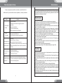
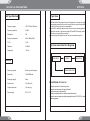
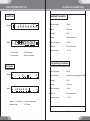
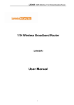
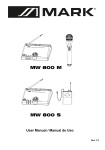
TROUBLESHOOTING
FOREWORD
Some corem problems and their solutions are identified in the
table below. If you are unable to solve a problem, contact your dealer.
Problem
No sound;RF light(s)
not glowing
No sound;
R F lights glowing.
Received signal is noisy c
contains extraneous sounds
sounds with transmitter on.
Solution
Make sure the transmitter
POWER switch is ON and the receiver is plugged into a power source
Check battery.
Check receiver squelch setting.
Check receiver antenna connection(s).
Make sure antennas are in line of sight of transmitter.
Turn up receiver audio VOLUME control
Check for proper connection between receiver and karaoke unit
Check battery
Remove local. Sources of RF interference.
If using a guitar or other instrument, check connections.
Two transmitters may be operating on the same frequency. Locate and turn one off.
Signal may be too weak Repositior~antennas. If possible, move them closer to
transmitter.
Thanks for purchasing our excellent wireless meeting microphone
products,please read this instruction carefully so that you can understand
how to operate the product you bought correctly, please store this book in
the safe place for reference in future.
Main features
1.Using VHF 170-270 Mhz band to avert interferencing frequency.
2.Using multilevel high frequency and mid frequency narrowband filter, so
as to dispel any possible interferencing signals.
3.A specially designed circuit switch is on the phone.It is for clearing up
waves of miscellaneous signals
4.All use quartz crystal oscillating circuits, so the frequency is very steady.
5.With audio compressing-expanding technology, the machine can lower
noises and increase the dynamic range. It can also lower reecho.
6.It has channel separate outputing and mix outputing, and it can be connected
with the sound-adjusting stage and the karaoke enlarge.
7.Special tone key locked identity functions to avoid interference signal
from outside open the mute system.
8.There are mulriple noise detect circuit ,multi circuits, So it has strong
anti-jamming specialty.
9.Uniform cardioid pickup pattern isolates the main sound source and
minimizes background noise
10.Effective, built-in spherical wind and pop filter.
11.Longest distance in open :100m.Idealest distance in open: 50m
Cautions
Noise from receiver with
transmitter off.
Momentary loss of sound as
transmitter is moved around
performing area.
Adjust receiver squelch control.
Remove local sources of RF interference.
Reposition receiver or antennas.
Reposition receiver and perform another"walkthrough"test and observe the
RF indicators. If audio dropouts persist, mark these"dead spots" in performing
area and avoid them during performance.
8
1.Please ensure the host receiver in the place where is in good condition
for signal, without dead angle.
2.Please keep the transmitter of microphone from throwing,casting, and
so on, protecting from broken.
3.The reciever without water-proof, so please keep it from water or something
like this.
4.Please keep distance with or away electromagnetic field,high voltage
power net or big metal subjects.
5.Please switch off the transmitter when you change the battery.
6.Please put out the battery if you will not use the microphone for long time.
7.Please plug out the reciever if you will not use the microphone for long time.
8.Please get contact with the distributor of the products if there is problem
on broken or something inside.
9.Please note we will not provide the service of repair if customer open it by
themself without notice.
1
TECHNICAL PARAMETERS
Unit Specification
SYSTEM
Operation
Frequency range
:
170-270.MHz VHF band
Frequency stability
:
0.005%
Modulation
:
FM
Frequency response
:
40Hz-18KHz( 3dB)
T.H.D
:
-0.8%
Distance
:
50-100M
Temperture
:
-10-55 c
1.Please take the following working flow diagram for reference on using
this machine-connect the mix out of receiver with mic input on the amplifier
or out A,B,C,D and mic input on the amplifier.
2.Power 220V, switch the power, set the volume of your sound equipment.
3.Adjust the volume in right sound, make MIC1 and MIC2 harmony, which
will make you enjoying the sound well.
4.Please plug out the power if you will not use the machine long time.
System connection flow diagram
RECIEVER
MIXER
AMPLIFIER
Reciever
Receiving system
:
Quartz crystal frequency
Sensitivity
:
10UV/40DB emf
Removing weight
:
50ms
Audio output
:
0-0.35Vp-p 5k
Output connection
:
¦6.3 mm plug
Power supply
:
DC:12-17 V
2
KAROKE AMPLIFIER
Installation of reciever
Keep the machine 1m above the ground
Keep the machine away 1m against the wall.
Pull the antenna up rightness fully
Make the transmitter point to the antenna without barrier
Keep the reciever away any digital equipment(such as CD,VCD,PC.or other
radio equipment)
7
FUNCTION DESCRIPTION
TECHNICAL PARAMETERS
Front Panel
Handheld Transmitter
8 ways
POWER
1
4 ways
CH-A VOL
CH-B VOL
CH-C VOL
CH-D VOL
3
3
3
3
2
1
VHF FOUR CHANNEL
MICROPHONE SYSTEM
2
3
CH-E VOL
CH-F VOL
CH-G VOL
CH-H VOL
3
3
3
3
4
4
+ 1
-
2
+VOLUME
-
-
3
1.Power switch
3.Volume adjust
3
+ 3
3
+ 4
-
Radio output power
:
>20mW
Antenna
:
Hide inside
Pre-weight
:
50 uS
Cartridge
:
Moving dynamic coil
Battery consumption
:
< 30mA
Battery life
:
8 H time of duration
Temperature range
:
-10 --55 ¡
POWER
3
1
2
2.Power indicator
4.Receiving indicator
Body packing transmitter
Rear panel
8 ways
A N T:D
ANT:C
ANT:B
ANT:A
1
1
12V
1
1
4
2.3
5
4 ways
1
1. Antenna
2
2
2
2
3
2.Audio output
4. balanced output
4
5
1
Radio output power
:
>20mW
Carrying frequency
:
below the min carrying frequency 40dB
Pre-weight
:
50 uS
Cartridge
:
condenser
Battery consumption
:
<30mA
Battery life
:
8 H time of duration
Temperature range
:
-10 --55 ¡
3.mixed- balance output
5.DC power
6
3
TECHNICAL PARAMETERS
TECHNICAL PARAMETERS
Wireless meeting microphone
Handheld transmitter
¢
This circle light is working, indicating the battery working when the
transmitter is switched on.
:
:
:
:
:
:
:
:
:
:
:
:
:
DC9V
<35mA
170-270MHz
¡0.002%
>90dB
> 80dB
>80dB
<3%
Condenser noise proof
Uni-direction
40Hz-18KHz( 3dB)
-47¡3dB @1KHz
-10-55¡
¢ ¢
¢
¢
¢Head net
¢Low voltage indicator
¢Power switch
¢9V Battery
¢Power light
¢Battery cover
Laveliar transmitter
Power indicator
OFF
LE
INPUT
Power switch
D
M
IC
Power supply
Power consumption
Carrying frequency
Frequency stability
S/N ratio
Channel interference ratio
Dynamic range
T.H.D
Cartridge
Polarity
Frequency response
Sensitivity of transmission
Temperture
ON
ON
O FF
1
2
tie clip conjuction
SS
LE
RE
R
L WI
NE CEIVE
AN
CH E RE
IN
ON
F TWROPH
MIC
VH
OP
EN
VHF TWIN CHANNEL WIRELESS
MICROPHONE RECEIVER
VHF
TWIN
MICR
CHAN
OPHO
NEL
NE
WIRE
RECE
IVER
LESS
OPEN
OP
4
Operation
3
1.Cartridge
collar line
EN
2.Working indicator
3.Switch
4.Power and low voltage two color indicator
4
1.Please put the battery in the battery case correctly with right poles
2.Working when the switch on,mute at ST-BY
3.Please out out the battery and switch off if you will not use.
4.Please change the battery when the low voltage light is on
5