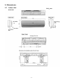
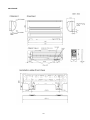
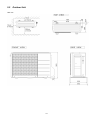
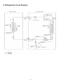
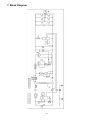
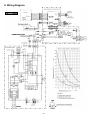
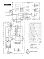
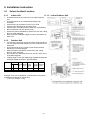
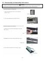
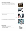
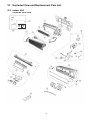
1
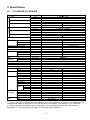
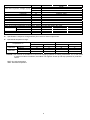
Order No: PHA-AG0903005C2 Indoor Unit CS-UE9JKE CS-UE12JKE Outdoor Unit CU-UE9JKE CU-UE12JKE WARNING This service information is designed for experienced repair technicians only and is not designed for use by the general public. It does not contain warnings or cautions to advise non-technical individuals of potential dangers in attempting to service a product. Products powered by electricity should be serviced or repaired only by experienced professional technicians. Any attempt to service or repair the products dealt with in this service information by anyone else could result in serious injury or death. TABLE OF CONTENTS 8.1 8.2 1. Safety Precautions.............................................3 CS-UE9JKE CU-UE9JKE ..........................18 CS-UE12JKE CU-UE12JKE ......................19 2. Specification .......................................................5 2.1 2.2 CS-UE9JKE CU-UE9JKE ............................5 CS-UE12JKE CU-UE12JKE ........................7 3. Features ..............................................................9 4. Location of Controls and Components .........10 4.1 4.2 4.3 Indoor Unit..................................................10 Outdoor Unit ...............................................10 Remote Control ..........................................10 5. Dimensions .......................................................11 5.1 5.2 Indoor Unit..................................................11 Outdoor Unit ...............................................13 6. Refrigeration Cycle Diagram...........................14 7. Block Diagram ..................................................15 8. Wiring Connection Diagram............................ 16 9. Installation Instruction.....................................18 9.1 9.2 9.3 Select the Best Location ............................18 Indoor Unit..................................................19 Outdoor Unit ...............................................21 10. Service Mode ....................................................24 10.1 Auto OFF/ON Button ..................................24 10.2 Select Remote Control Transmission Code24 10.3 Operate and Display of Remote Control ....25 11. Operation Control.............................................27 11.1 11.2 11.3 Basic Function............................................27 Indoor Fan Motor Operation.......................28 Outdoor Fan Motor Operation ....................28 12. Protection control ............................................31 © Panasonic Home Appliances Air-Conditioning (Guangzhou) Co., Ltd. 2008. Unauthorized copying and distribution is a violation of law. 12.1 12.2 12.3 Protection Control For All Operations.........31 Protection Control For Cooling and Soft Dry Operation....................................................32 Outdoor Air Temperature Control...............33 13. Troubleshooting Guide....................................35 13.1 13.2 Refrigeration Cycle System........................35 Break Down self Diagnosis Function..........35 14. Disassembly and Assembly Instructions ......38 15. Exploded View and Replacement Pars List...41 15.1 15.2 Indoor Unit ..................................................41 Outdoor Unit ...............................................43 2 1. Safety Precautions • • • Read the following “SAFETY PRECAUTIONS” carefully before perform any servicing. Electrical work must be installed or serviced by a licensed electrician. Be sure to use the correct rating of the power plug and main circuit for the model installed. The caution items stated here must be followed because these important contents are related to safety. The meaning of each indication used is as below. Incorrect installation or servicing due to ignoring of the instruction will cause harm or damage, and the seriousness is classified by the following indications. This indication shows the possibility of causing death or serious injury WARNING CAUTION • This indication shows the possibility of causing injury or damage to properties. The items to be followed are classified by the symbols: Symbol with white background denotes item that is PROHIBITED from doing. Symbol with dark background denotes item that must be carried out. • Carry out test run to confirm that no abnormality occurs after the servicing. Then, explain to user the operation, care and maintenance as stated in instructions. Please remind the customer to keep the operating instructions for future reference. WARNING 1. Engage dealer or specialist for installation. If installation done by the user is defective, it will cause water leakage, electrical shock or fire. 2. Install according to this installation instructions strictly. If installation is defective, it will cause water leakage, electrical shock or fire. 3. Use the attached accessories parts and specified parts for installation. Otherwise, it will cause the set to fall, water leakage, fire or electrical shock. 4. Install at a strong and firm location which is able to withstand the set’s weight. If the strength is not enough or installation is not properly done, the set will drop and cause injury. 5. Do not install outdoor unit near handrail of veranda. When installing air-conditioner unit at veranda of high rise building, child may climb up to outdoor unit and cross over the handrail and causing accident. 6. For electrical work, follow the local national wiring standard, regulation and this installation instruction. An independent circuit and single outlet must be used. If electrical circuit capacity is not enough or defect found in electrical work, it will cause electrical shock or fire. 7. This equipment is strongly recommended to be installed with Earth Leakage Circuit Breaker (ELCB) or Residual Current Device (RCD). Otherwise, it may cause electrical shock and fire in case equipment breakdown or insulation breakdown. 8. This equipment must be properly earthed. Earth line must not be connected to gas pipe, water pipe, earth of lightning rod and telephone. Otherwise, it may cause electrical shock in case equipment breakdown or insulation breakdown. 9. Use the specified cable (1.5 mm2) and connect tightly for indoor/outdoor connection. Connect tightly and clamp the cable so that no external force will be acted on the terminal. If connection or fixing is not perfect, it will cause heat-up or fire at the connection. 10. Wire routing must be properly arranged so that control board cover is fixed properly. If control board cover is not fixed perfectly, it will cause fire or electrical shock. 11. When carrying out piping connection, take care not to let air substances other than the specified refrigerant go into refrigeration cycle. Otherwise, it will cause lower capacity, abnormal high pressure in the refrigeration cycle, explosion and injury. 12. Do not damage or use unspecified power supply cord. Otherwise, it will cause fire or electrical shock. 13. Do not modify the length of the power supply cord or use extension cord, and do not share the single outlet with other electrical appliances. Otherwise, it will cause fire or electrical shock. 14. • For R410A models, when connecting the piping, do not use any existing (R22) pipes and flare nuts. Using such same may cause abnormally high pressure in the refrigeration cycle (piping), and possibly result in explosion and injury. Use only R410A materials. • Thickness or copper pipes used with R410A must be more than 0.8 mm. Never use copper pipes thinner than 0.8 mm • It is desirable that the amount of residual oil is less than 40 mg/10 m. 15. During installation, before run the compressor, confirm the refrigeration pipes are fixed. Operation of compressor without fixing the piping, setting the 2 way valve and 3-way valve at open condition, a burst may occur and cause injury. 16. During pump down operation, stop the compressor before remove the refrigeration piping. When remove piping while 2-way valve, 3 way valve at open condition, burst may occur and cause injury. 3 17. After completion of installation, confirm there is no leakage of refrigerant gas. It may generate toxic gas when the refrigerant contacts with fire. 18. Ventilate if there is refrigerant gas leakage during operation. It may cause toxic gas when the refrigerant contacts with fire. 19. Recommended installation height for indoor unit shall be at least 2.5 m. 20. The appliance shall be installed in accordance with national wiring regulations. 21. Keep away from small children, the thin film may cling to nose and mouth and prevent breathing. 22. Do not insert your fingers or other objects into the unit, high speed rotating fan may cause injury. 23. Do not modify the machine, part, material during repairing service. 24. Must not use other parts except original parts describe in catalog and manual. CAUTION 1. Do not install the unit at place where leakage of flammable gas may occur. In case gas leaks and accumulates at surrounding of the unit, it may cause fire. 2. Carry out drainage piping as mentioned in installation instructions. If drainage is not perfect, water may enter the room and damage the furniture. 3. Tighten the flare nut with torque wrench according to specified method. If the flare nut is over-tightened, after a long period, the flare may break and cause refrigerant gas leakage. 4. Do not touch outdoor unit air inlet and aluminums fin. It may cause injury. 5. Select an installation location which is easy for maintenance. 6. Power supply connection to the air conditioner. Connect the power supply cord of the air conditioner to the mains using one of the following methods. Power supply point should be in easily accessible place for power disconnection in case of emergency. In some countries, permanent connection of this air conditioner to the power supply is prohibited. 1) Power supply connection to the receptacle using a power plug. Use an approved 15/16A power plug with earth pin for the connection to the receptacle. 2) Power supply connection to a circuit breaker for the permanent connection. Use an approved 16A circuit breaker for the permanent connection. It must be a double pole switch with a minimum 3.5 mm contact gap. 7. Do not release refrigerant. Do not release refrigerant during piping work for installation, re-installation and during repairing a refrigeration parts. Take care of the liquid refrigerant, it may cause frostbite. 8. Installation and service work. It may need two people to carry out the installation and service work. 9. Do not install this appliance in a laundry room or other location where water may drip from the ceiling, etc. 10. Do not sit ot step on the unit, you may fall down accidentally. 11. Do not touch the sharp aluminium fin, sharp parts may cause injury. 12. Thermal fuse specification for indoor unit: 250V 3.15A T3.15AL; outdoor unit: 205V 3.15A T3.15AL,205V 20A T20AL. 4 2. Specification 2.1 CS-UE9JKE CU-UE9JKE Item COOLING Capacity HEATING Capacity EER Noise Level COP Noise Level Moisture Removal Air Volume Lo Me Hi Refrigerant Control Device Refrigerant Oil (Charged) Refrigerant (Charged) R410A Dimension Height Width Depth Net Weight Pipe Gas Diameter Liquid Pipe Length Height Difference Additional Gas Amount Refrigerant Charge Less Drain Hose Inner diameter Length Compressor Type Motor Type Rated Output Fan Type Material Motor Type Input power Output power Fan Lo Speed Me Hi Heat Fin material Exchanger Fin type Row x stage x FPI Size (W x H x L) Air Filter Material Type Style Unit kW BTU/h W/W BTU/hW dB(A) Power level dB kW BTU/h W/W BTU/hW dB(A) Power level dB l/h (pt/h) m3/m (ft3/m) m3/m (ft3/m) m3/m (ft3/m) cm3 kg (oz) mm (inch) mm (inch) mm (inch) kg (lbs) mm (inch) mm (inch) m (ft) m (ft) g/m (oz/ft) m (ft) mm mm W W W rpm rpm rpm mm Indoor Unit Outdoor Unit 2.50(0.90~3.00) 8530(3070~10230) 3.33(4.73~3.00) 11.37(16.15~10.23) Hi: 42 Lo: 27 QLo: 22 Hi: 46 53 59 3.30(0.90~4.00) 11260(3070~13650) 3.66(4.09~3.33) 12.51(13.95~11.37) Hi: 42 Lo: 27 QLo: 25 Hi: 47 53 60 1.4 2.4 6.15(232) 7.93(300) 10.08 (381) 28.9(1020) Capillary Tube RB68A or Freol Alpha68M 0.78 (27.5) 250 (9-27/32) 540 (21-1/4) 770 (30-5/16) 780 (30-23/32) 205 (8-1/16) 289 (11-3/8) 7.0 28 (62) 9.52 (3/8) 6.35 (1/4) 3 (9.8) - 15(49.2) 5 (16.4) 20 (0.2) 7.5 (24.6) 14 500 Rotary Induction (6-poles) 750 Cross-Flow Fan Propeller Fan AS PP Induction (8-poles) Induction (6-poles) 30 15 830 1070 1360 750 Aluminium (Pre Coated) Aluminum ( Pre Coated) Slit Fin Slit Fin 2 x 12 x 18 1 x 24 x 17 610 x 315 x 25.4 709 x 504 x 18.2 P.P.HONEY COMB One-Touch - 1. Cooling capacities are based on indoor temperature of 27°C Dry Bulb (80.6°F Dry Bulb), 19°C Wet Bulb (66.2°F Wet Bulb) and outdoor air temperature of 35°C Dry Bulb (95.0°F Dry Bulb), 24°C Wet Bulb (75.2°F Wet Bulb). 2. Heating capacities are based on indoor temperature of 20°C Dry Bulb (80.6°F Dry Bulb) and outdoor air temperature of 7°C Dry Bulb (44.6°F Dry Bulb), 6°C Wet Bulb (42.8°F Wet Bulb). 5 Item Unit Single φ Power Source (Phase, Voltage, Cycle) V 230 Hz 50 Input Power COOLING W 750(190~1000) HEATING W 900(220~1200) Starting Current A 4.10 Running Current COOLING A 3.60 HEATING A 4.10 Maximum Current A 5.50 Power Factor COOLING % 90 HEATING % 95 Power factor means total figure of compressor, indoor fan motor and outdoor fan motor. Power Cord Number of core 3 (1.5mm) Length m 1.3 Thermostat Electronic Control Protection Device Electronic Control Note z Specification is subject to change without prior notice for further improvement. z Operational temperature range: Temperature °C COOLING HEATING Maximum Minimum Maximum Minimum Indoor *WBT * DBT 32 16 30 16 Outdoor *WBT *DBT 23 11 - 43 16 24 -5 26 11 18 -6 NOTICE: This model is not suitable for 24 hours non-stopping operation in heating mode below -5°C. If this model is used out of above conditions, the outdoor unit might be frozen up and stop operation for protection control. *DBT: Dry bulb temperature *WBT: Wet bulb temperature 6 2.2 CS-UE12JKE CU-UE12JKE Item Outdoor Unit Capacity 3.50(0.90~3.90) 11940(3070~13300) EER 3.30(5.29~3.25) 11.26(18.06~11.08) Noise Level Hi: 42 Lo: 30 QLo: 22 Hi: 48 Hi: 53 Lo: Hi: 61 Capacity 4.25(0.90~4.70) 14490(3070~16030) COP 3.63(6.00~3.56) 12.38(20.47~12.14) Noise Level Hi: 42 Lo: 33 QLo: 25 Hi: 50 Hi: 53 Lo: Hi: 63 Moisture Removal 2.0 3.5 Air Volume Lo 8.1(285) Me 9.9(349) Hi 11.7 (413) 30.5 (1076) Refrigerant Control Device Capillary Tube Refrigerant Oil (Charged) cm3 RB68A or Freol Alpha68M Refrigerant (Charged) R410A kg (oz) 0.97 (34.2) Dimension Height mm (inch) 280 (11-1/32) 540 (21-1/4) Width mm (inch) 799 (31-15/32) 780(30-23/32) Depth mm (inch) 183 (7-13/64) 289 (11-3/8) Net Weight kg (lbs) 8.5 (19) 30 (66) Pipe Gas mm (inch) 9.52 (3/8) Diameter Liquid mm (inch) 6.35 (1/4) Pipe Length m (ft) 3 (9.8) - 15 (49.2) Height Difference m (ft) 5 (16.4) Additional Gas Amount g/m (oz/ft) 20 (0.2) Refrigerant Charge Less m (ft) 7.5 (24.6) Drain Hose Inner diameter mm 14 Length mm 500 Compressor Type Rotary Motor Type Induction (6-poles) Rated Output W 900 Fan Type Cross-Flow Fan Propeller Fan Material AS PP Motor Type Induction (8-poles) Induction (6-poles) Input power W Output power W 30 25 Lo (Cool) rpm 940 Fan Speed Me (Cool) rpm 1160 Hi (Cool) rpm 1370 870 Heat Fin material Aluminum (Pre Coated) Aluminum (Pre Coated) Exchanger Fin type Slit Fin Slit Fin Row x stage x FPI 2 x 15 x 20 2 x 24 x 17 Size (W x H x L) mm 610 x 315 x 25.4 709 x 540 x 36.4 Air Filter Material P.P.HONEY.COMP Type Style One-Touch 1. Cooling capacities are based on indoor temperature of 27°C Dry Bulb (80.6°F Dry Bulb), 19°C Wet Bulb (66.2°F Wet Bulb) and outdoor air temperature of 35°C Dry Bulb (95.0°F Dry Bulb), 24°C Wet Bulb (75.2°F Wet Bulb). 2. Heating capacities are based on indoor temperature of 20°C Dry Bulb (80.6°F Dry Bulb) and outdoor air temperature of 7°C Dry Bulb (44.6°F Dry Bulb), 6°C Wet Bulb (42.8°F Wet Bulb). COOLING HEATING Unit kW BTU/h W/W BTU/hW dB(A) Power level dB kW BTU/h W/W BTU/hW dB(A) Power level dB l/h (pt/h) m3/m (ft3/m) m3/m (ft3/m) m3/m (ft3/m) Indoor Unit 7 Item Unit Single 230 50 Input Power COOLING 1060(170~1200) HEATING 1170(150~1320) Starting Current 5.20 Running Current COOLING 4.70 HEATING 5.20 Maximum Current 6.80 Power Factor COOLING 98 HEATING % 98 Power factor means total figure of compressor, indoor fan motor and outdoor fan motor. Power Cord Number of core 3 (1.5mm) Length m 1.3 Thermostat Electronic Control Protection Device Electronic Control Note z Specification is subject to change without prior notice for further improvement. Power Source (Phase, Voltage, Cycle) z V Hz W W A A A A Operational temperature range: Temperature °C COOLING HEATING Maximum Minimum Maximum Minimum Indoor *WBT * DBT 32 16 30 16 Outdoor *WBT *DBT 23 11 - 43 16 24 -5 26 11 18 -6 NOTICE: This model is not suitable for 24 hours non-stopping operation in heating mode below -5°C. If this model is used out of above conditions, the outdoor unit might be frozen up and stop operation for protection control. *DBT: Dry bulb temperature *WBT: Wet bulb temperature 8 3. Features • Inverter Technology o Wider output power range o Energy saving o Quick Cooling o More precise temperature control • Long Installation Piping o CS/CU-UE9/12JKE, long piping up to 15 meters. • Easy to use remote control • Quality Improvement o Random auto restart after power failure for safety restart operation o Gas leakage protection o Prevent compressor reverse cycle o Inner protector to protect compressor • Operation Improvement o Quiet mode to reduce the indoor unit operating sound o Powerful mode to reach the desired room temperature quickly o 12-hour timer • Serviceability Improvement o Breakdown Self Diagnosis Function. 9 4. Location of Controls and Components Indoor Unit 4.1 Outdoor Unit 4.2 Remote Control Transmitter OFF/ON Operation mode Fan speed selection Temperature setting Timer setting Airflow direction adjustment z z 10 For normal operation, the ERROR RESET button is not in use. Press RESET button to restore the remote control’s default setting. 5. Dimensions 5.1 Indoor Unit Unit:mm CS-UE9JKE 11 CS-UE12JKE 12 5.2 Outdoor Unit Unit: mm 13 6. Refrigeration Cycle Diagram 14 7. Block Diagram 15 8. Wiring Diagram CS/CU-UE9JKE 16 CS/CU-UE12JKE 17 9. Installation Instruction 9.1 9.1.1 • • • • • • • • • • • • 11.1.3 Indoor/Outdoor Unit Indoor Unit There should not be any heat source or steam near the unit. There should not be any obstacles blocking the air circulation. A place where air circulation in the room is good. A place where drainage can be easily done. A place where noise prevention is taken into consideration. Do not install the unit near the door way. Ensure the spaces indicated by arrows from the wall, ceiling, fence or other obstacles. Recommended installation height for indoor unit shall be at least 2.5m. 9.1.2 • Select the Best Location Outdoor Unit If an awning is built over the unit to prevent direct sunlight or rain, be careful that heat radiation from the condenser is not obstructed. There should not be any animal or plant which could be affected by hot air discharged. Keep the spaces indicated by arrows from wall, ceiling, fence or other obstacles. Do not place any obstacles which may cause a short circuit of the discharged air. If piping length is over the rated length, additional refrigerant should be added as shown in the table below: Model Piping size Rated Max Min Gas Liquid Length Elevati Piping (m) on (m) Length (m) UE9JKE 3/8” 1/4" 7.5 5 3 UE12JKE 3/8” 1/4” 7.5 5 3 Max Additional Piping Refrigera Length nt (g/m) (m) 15 20 15 20 Example: If the unit is installed at a 10m distance, the quantity of additional refrigerant should be 50 g. …… (10-7.5) m x 20g/m = 50 g 18 9.2 9.2.1 Indoor Unit How to Fix Installation Plate The centre of installation plate should be at more than 450mm at right and left of the wall. The distance from installation plate edge to ceiling should be more than 67mm. From installation plate left edge to unit's left side is 62mm (UE9JKE) or 98mm (UE12JKE). From installation plate right edge to unit's right is 79mm (UE9JKE) or 112mm (UE12JKE). B ○ : For left side piping, piping connection for liquid should be about 10 mm from this line. : For left side piping, piping connection for gas should be about 45mm from this line. : For left side piping, piping connecting cable should be about 785mm (UE9JKE) or 800mm (UE12JKE) from this line. 1 Mount the installation plate on the wall with 5 screws or more. (If mounting the unit on the wall, consider using anchor bolts.) Always mount the installation plate horizontally by aligning the marking-off line with the thread and using a level gauge. 2 Drill the piping plate hole with ø70 mm hole-core drill. z Put measuring tape at position as shown in the diagram above. The hole centre is obtained by measuring the distance namely 105mm and 145mm for left and right hole respectively (UE9JKE), or 150mm and 125mm for (UE12JKE). z Drill the piping plate hole at either the right or left and the hole should be slightly slanted to the outdoor side. 9.2.2 1 2 3 To Drill a Hole in the Wall and Install a Sleeve of Piping Insert the piping sleeve to the hole. Fix the busing to the sleeve. Cut the sleeve until it extrudes about 15mm from the wall Caution When the wall is hollow, please be sure to use the sleeve for tube ass’y to prevent dangers caused by mice biting the connecting cable. 4 Wall Indoor 15 mm Sleeve for tube ass’y Approx. 5 - 7 mm Finish by sealing the sleeve with putty or caulking compound at the final stage. Bushing for tube ass’y Ø 70 through hole 19 Outdoor Putty or caulking compound 9.2.3 Indoor Unit Installation 20 9.2.4 Connect the Cable to the Indoor Unit 1 2 The inside and outside connecting cable can be connected without removing the front grille. Connecting cable between indoor unit and outdoor unit shall be approved polychloroprene sheathed 4x 1.5mm2 flexible cords, type designation 245 IEC 57 or heavier cord. Ensure the color of wires of outdoor unit and the terminal numbers are the same to the indoor’s respectively. Earth lead wire shall be longer than the other lead wires as shown in the figure for the electrical safety in case of the slipping out of the cord from the anchorage. 3 Wire stripping and connecting requirement. 9.3 Outdoor Unit 9.3.1 Install the Outdoor Unit After selecting the best location, start installation according to indoor/outdoor unit installation diagram. 1 Fix the unit on concrete or rigid frame firmly and horizontally by bolt nut (ø10 mm). A B 2 When installing at roof, please consider strong wind and earthquake. Please fasten the installation stand firmly with bolt or nails. C • Secure the cable onto the board with the holder (clamper). 9.3.2 B 104 C 13.5 D 320 D A 570 Connecting the Piping 9.3.2.1 Connecting the piping to indoor unit Please make flare after inserting flare nut (locate at joint portion, of tube assembly) onto the copper pipe. (In case of using long piping) Connect the piping • Align the center of piping and sufficiently tighten the flare nut with fingers. • Further tighten the flare nut with torque wrench in specified torque as stated in the table. Model Spanner or Wrench Torque wrench Piping size (Torque) Gas Liquid UE9JKE 3/8” (42N•m) 1/4" (18N•m) UE12JKE 3/8" (42N•m ) 1/4" (18N•m) Caution : Do not over tighten, over tightening cause gas leakage 21 Connecting the piping to outdoor unit Decide piping length and then cut by using pipe cutter. Remove burrs from cut edge. Make flare after inserting the flare nut (locate at valve) onto the copper pipe. Align center of piping to valves and then tighten with torque wrench to the specified torque as stated in the table. 9.3.2.2 Cutting and flaring the piping 1 2 3 Please cut using pipe cutter and then remove the burrs. Remove the burrs by using reamer. If burrs are not removed, gas leakage may be caused. Turn the piping end down to avoid the metal powder entering the pipe. Please make flare after inserting the flare nut onto the copper pipes. Improper flaring P ip e R ea m e r H a n d le B ar Yo k e C o re B ar 0 – 0 .5 m m I n c l in e d S u r f a c e C ra c k e d U n e v e n dam aged t h ic k n e s s P o in t d o w n 1. To cut 9.3.3 2. To remove burrs C la m p h a n d le R e d a r ro w m a r k 3. To flare C o p p e r p ip e When properly flared, the internal surface of the flare will evenly shine and be of even thickness. Since the flare part comes into contact with the connections, carefully check the flare finish. Evacuation of the equipment When installing an air conditioner, be sure to evacuate the air inside the indoor unit and pipes in the follwing procidure. Outdoor Unit Terminal board Over 5mm Control board cover To indoor unit Liquid side Gas side 2-way valve (Open) Cap 3-way valve (Open) Hexagonal wrench Service port cap 1 2 3 4 5 6 7 8 Connect a charging hose with a push pin to the low side of a charging set and the service port at the 3-way valve. z Be sure to connect the end of charging hose with the push pin to the service port. z The size of charging hose fitting should be 1/2 UNF, 20 threads. Connect the center hose of the charging set to a vacuum pump with check valve, or vacuum pump and vacuum pump adaptor. Turn on the power switch of the vacuum pump and make sure that the needle in the gauge moves from 0 cmHg (0 Mpa) to –76 cmHg (-0.1 Mpa). Then evacuate the air approximately ten minutes. Close the Low side valve of the charging set and turn off the vacuum pump. Make sure that the needle in the gauge does not move after approximately five minutes. Note: BE SURE TO FOLLOW THIS PROCEDURE IN ORDER TO AVOID REFRIGEANT GAS LEAKAG Disconnect the charging horse from the vacuum pump and from the service port of the 3-way valve. Tighten the service port caps of the 3-way valve at a torque of 18 N.m with a torque wrench. Remove the valve caps of both of the 2-way valve and 3-way valve. Position both of the valves to “OPEN” using a hexagonal wrench (4mm). Mount valve caps onto the 2-way and the 3-way valve. z Be sure to check for gas leakage. CAUTION: ● If gauge needle does not move from 0 cmHg (0 MPa) to -76 cmHg (-0.1 MPa), in step 3 above take the following measure: ● If the leak stops when the piping connections are tightened further, continue working from step 3. 22 ● If the leak does not stop when the connections are retightened, repair the location of leak. ● Do not release refrigerant during piping work for installation and reinstallation. Take care of the liquid refrigerant, it may cause frostbite. 9.3.4 Connect the cable to the Outdoor Unit 1 2 Remove the control board cover from the unit by loosening the screw. Connecting cable between indoor unit and outdoor unit shall be approved polychloroprene sheathed 4x 1.5mm2 flexible cord, type designation 245 IEC 57 or heavier cord. 3 4 5 Secure the cable onto the control board with the holder (clamper). Attach the control board cover back to the original position with the screw. For wiring stripping and connection requirement, refer to instruction 9.2.4 of indoor unit. 9.3.5 1 2 Pipe Insulation Please carry out insulation at pipe connection portion as mentioned in Indoor/Outdoor Unit Installation Diagram. Please warp the insulated piping end to prevent water from going inside the piping. If drain hose or connecting piping is in the room (where dew may form), please increase the insulation by using POLY-E-FOAM with thickness 6mm or above. 23 10. Service Mode 10.1 Auto OFF/ON Button Auto OFF/ON Button Pressed 1. AUTO OPERATION MODE Once the Auto OFF/ON button is slightly pressed, the unit will immediately operate in Auto operation. This operation can be used to operate air conditioner with limited function if remote control is misplaced or malfunction. 2. TEST RUN OPERATION( FOR PUMP DOWN/ SERVICING PURPOSE) Press the button continuously for approximate 5 second and then release. A “beep” sound will be heard to identify the starting of TEST RUN OPERATION. 3. HEATING OPERATION A) Within 5 minutes after TEST RUN operation starting, press the button again for more than 5 seconds until 2 “beep” sounds are heard, the unit will operate in heating mode. B) Pressed the button continuously for approximate 8 second and then released. 2 “beep” sounds will be heard to identify the starting of HEATING operation. 4. DIFFERENT CONTROLLING SETTING. Press the button continuously for approximate 11 until 3 “beep” sounds are heard and together with the signal from remote controller, the unit can be changed to different controlling setting. For transmission code selection method, please refer to “Select Remote Control Transmission Code” 5. INDIVIDUAL COUNTER-ACTION When the switch is continuously pressed between 16 to 21 seconds, either H14 error detection selection mode or remote controller’s signal receiving sound can be cancelled or turned on. 10.2 Select Remote Control Transmission Code There are 4 types of remote control transmission code could be selected and stored in EEPROM of indoor PCB. The indoor unit will only operate when received signal with same transmission code from remote control. This could prevent signal interference when there are 2 or more indoor units installed near by together. To Change the code of remote controller, following table I to join or cut jumper wire on the remote controller and setting with "Forced operation button". Four codes (A, B, C, D) can be selected. Taking code "B" for example, the process below should be follow. 1. Press the "Auto OFF/ON” button on the indoor unit for approximate 11 seconds until 3 "Beep’s signal receiving sounds are heard. 2. Within 5 minutes, gently press the "ERROR RESET" button on the remote control towards the indoor unit. One "Beep" sound is heard. 3. Within 60 seconds, press any button on the remote control, the frequency of which was set as "B". Setting is completed after a "Beep" sound is heard. The corresponding signal sent by remote control "B" will be received by this indoor unit Table 1 Remote control A(STANDARD) B C D J02 SHORT OPEN SHORT OPEN J03 OPEN OPEN SHORT SHORT 24 10.3 Operate and Display of Remote Control 10.3.1 Original setting 10.3.2 Mode selecting button AUTO, HEAT, COOL, DRY can be selected by pressing “MODE” button. Initial display of LCD is as follow *Keeping the button depressed continuously, the operation mode will change in the following order in turn AUTO—HEAT—COOL—DRY--AUTO 10.3.3 Temperature adjusting button Temperature adjusting range is between 16 ℃~30 ℃ 10.3.4 Fan speed button There are 5 speed levels can be selected. The display on the remote controller changes as follows by pressing the AIR SWING button. 10.3.5 AIR SWING button To adjust vertical airflow directions by pressing AIR SWING button (5 options) 10.3.6 QUIET/POWERFULL button Press this button to switch among QUIET operation, POWERFUL operation and normal operation. Start Quiet operation: Press this button until “QUIET” displaying on remote control display to identify Quiet mode operating. Start POWERFUL operation: Press this button until POWERUL displays on remote control display to identify Quiet mode operating. Switch Quiet /Powerful operation to normal operation: Press this button until “QUIET” and ”POWERFUL” on remote control display disappear, which identifies the unit returns to normal operation. Note: QUIET and POWERFUL operation can not be active simultaneously. 25 10.3.7 Timer setting button There are 4 types of timer setting by pressing Timer setting button: ON-TIMER, OFF-TIMER, ON-OFF TIMER, OFFON TIMER. 1) SELECT button When the air conditioner is ON, OFF-TIMER or OFF-ON TIMER can be selected by pressing SELECT button. AUTO HEAT COOL DRY When the air conditioner is turned off, ON-TIMER or ON-OFF-TIMER can be selected. AUTO HEAT COOL DRY 2) Button A and B Pressing button A can change the time for ON-TIMER and OFF-TIMER, off time for OFF-ON Timer, on time for ON-OFF TIMER; Pressing button B can change the on time for OFF-ON Timer and off time for ON-OFF Timer setting. 3) SET/CANCEL button. Pressing the button to set or cancel the set timer during the timer setting or activate the previous timer setting. After the timer setting is determined, “ON” or “OFF” will stop flashing. If the timer setting is cancelled, “ON” or “OFF” will disappear on the remote control display. NOTE: OFF Timer and OFF- ON Timer can only be set during the operation; Timer setting can operate only once. If the OFF/ON button on the remote control or the AUTO Switch on the indoor unit is pressed, the timer setting will be cancelled. If Auto Restart Control occurs, timer setting will be cancelled. During the operation, if the ON Timer or ON-OFF Timer is set, the operation will be stopped. 10.3.8 About Cursor Key Which Points To “OFF” On Remote Control When the ON/OFF button on the remote control is pressed, the cursor key which points to “OFF” will appear or disappear to indicate the ON/OFF status of the air conditioner. AUTO HEAT COOL DRY AUTO HEAT COOL DRY For some reason (Ex. The signal of the remote control does not reach the signal receiver of the indoor unit.), the display of the remote control will not correspond with the actual ON/OFF status of the indoor unit: 1. 2. The air conditioner is running but the cursor key which points to “OFF” appears. The air conditioner can be stopped with any button (Except for “ON/OFF”, “TIMER SET”, “TIMER ON”) pressed. The air conditioner is on standby, but the cursor key which points to “OFF” disappears. The air conditioner can be started with any button (Except for “ON/OFF”, “TIMER SET”, “TIMER OFF”) pressed. 26 11. Operation Control 11.1 Basic Function 11.1.1 Internal Setting Temperature Once the operation starts, remote control setting temperature will be taken as base value for temperature shifting processes. These shifting processes are depending on the air conditioner settings and the operation environment. The final shifted value will be used as internal setting temperature and it is updated continuously whenever the electrical power is supplied to the unit. Remote Control Setting Temp. (16℃~30℃) Indoor Air Temperature Shifting Internal Setting Temperature Outdoor Air Temperature Shifting Powerful Temperature Limit Checking ( Min:16 ℃; Mac:33℃) Internal Setting Temperature 11.1.2 Cooling Operation 11.1.2.1 Thermostat control • Compressor is OFF when Intake Air Temperature - Internal Setting Temperature < -1.5℃ • Compressor is ON after waiting for 3 minutes, if the Intake Air Temperature - Internal Setting Temperature > Compressor OFF point. 11.1.3 11.1.3.1 11.1.4 11.1.4.1 Soft Dry Operation Thermostat control (The same as Cooling mode) Heating operation Thermostat control • Compressor is OFF when Intake Air Temperature - Internal Setting Temperature > +2.0℃ • Compressor is ON after waiting for 3 minutes, if the Intake Air Temperature - Internal Setting Temperature< Compressor OFF point. 11.1.5 Automatic Operation 1. Once AUTO mode is selected, operation mode is determined by set temperature of remote control, indoor intake temperature and outdoor temperature. 2.During operating mode judgment, indoor fan runs at min Lo- fan speed and outdoor fan runs in the purpose of detecting the intake air temperature and outdoor air temperature (for 30 seconds) 27 11.2 Indoor Fan Motor Operation Basic Rotation Speed i. Manual Fan speed Fan motor’s number of rotation is determined according to remote control setting. Remote control Tab COOLING(rpm) HEATING(rpm) COOLING(rpm) HEATING(rpm) Model CS-UE9JKE CS-UE12JKE O Hi 1360 1420 1370 1440 O Me+ 1190 1270 1270 1340 O Me 1070 1150 1160 1260 O Me950 1030 1050 1180 O Lo QUIET QLo 720 830 840 1010 830 910 940 1100 ii. Auto Fan Speed (Cooling, Soft Dry Mode) According to room temperature and setting temperature, indoor fan speed is determined automatically. The indoor fan will operate according to pattern below. Fan speed Higher A b c d e f g h a b Medium Lower B. Feedback control • Immediately after the fan motor started, feedback control is performed once every second. • During fan motor on, if fan motor feedback 2550 rpm or < 50 rpm continue for 10 seconds, then fan motor error counter increases, fan motor then stops and restarts. If the fan motor counter becomes 7 times, then H19 - fan motor error is detected. Operation stops and cannot on back. 11.3 Outdoor Fan Motor Operation Outdoor fan motor is operated with one fan speed only. It starts when compressor starts operation and it stops 30 seconds after compressor stops operation. ON ON Compressor OFF Outdoor Fan ON OFF Airflow Direction 30 s 11.3.1 Vertical Airflow 1 2 3 4 31o 40o 5 Operating Mode 10o Cooling Auto 22o 10o ~50o Normal o 35o(Begining of POWERFUL mode) , 6o 18 Powerful 10o Soft dry Auto 31o 40o 50o o 12 Powerful 12o 8o Auto 22o Normal Heating 50o 24o 37o 51o Normal 8o, 9o, 39o , 41o , Powerful 8 , 9 , 35 , 39 , o o o 63o o 1. Automatic vertical airflow direction can be set using remote control; the vane swings up and down within the angles as stated above. For heating mode operation, the angle of the vane depends on the indoor heat exchanger temperature. When the air conditioner is stopped using remote control, the vane will shift to close position. 28 2. Manual vertical airflow direction can be set using remote control. The angels of the vane are as stated above. When the air conditioner is stopped using remote control, the vane will shift to close position. * Above angle data is for reference only. 11.3.2 Horizontal Airflow The horizontal airflow direction louvers can be adjusted manually by hand. 11.3.3 Quiet operation ● To provide quiet operation comparing to normal operation. The Quiet operation can be active or stop by pressing QUIET/POWERFUL button on remote control. ● Once Quiet mode is active, the unit will continuously operate in QUIET Mode until cancel the mode by pressing QUIET/POWERFUL button on remote control. 11.3.4 Powerful operation ● To cooling or heating the room faster comparing to normal operation. The POWERFUL operation can be active or stop by pressing QUIET/POWERFUL button on remote control. ● When powerful operation is active, the unit will continuously operate in POWERFUL mode until cancel the mode by pressing QUIET/POWERFUL button on remote control. Operation details are as the fig. below. 1. For cooling, soft Dry mode Power Button pressed Min.5’ Fast Cooling PIPING TEMP. (COOLING) D C B A Cooling, Soft Dry 1130 (Max) Shi 45 seconds FAN SPEED ( rpm) AUTO 730 (Min.) 20 ‘ Correction Factor(℃) 20 ‘ 20 ‘ -1.67 20 ‘ +0.25 -0.25 -1.00 ON OFF 2. For Heating mode: Power Button pressed Min.5’ Fast Heating1 PIPING TEMP. (COOLING) FAN SPEED ( rpm) Heating D C B A 1270 (Max) Shi 45 seconds AUTO 940 (Min.) Correction Factor(℃) +1.00 +0.25 +2 20 ‘ 20 ‘ +0.25 20 ‘ 20 ‘ ON OFF Note: The value of A, B, C, D will change according to the indoor temperature. 29 11.3.5 Automatic Restart Control When the power supply is cut off during the operation of air conditioner, the compressor will re-operate within three to four minutes after power supply resumes. 11.3.6 Indication Panel LED Color Light ON Light OFF POWER Green Operation ON Operation OFF TIMER Orange Timer setting ON Timer setting OFF Note: ● If POWER LED blinks, the possible operation of the unit is operation mode judgment, or ON timer sampling. ● If Timer LED blinks, there is an abnormal operation occurs. 11.3.7 Timer control Delay ON Timer can be set using remote controller, the unit with timer set will start operate earlier than the setting time. This is to provide a comfortable environment when reaching the set ON time. Seventy minutes before the set time for ON Timer or ON-OFF Timer setting, indoor ( at fan speed of Lo-) and outdoor fan motor start operate for 30 seconds to determine the indoor intake air temperature and outdoor air temperature in order to judge the operation mode. From the above judgment, the decided operation will start operate earlier than the set time as shown below. 35 Timer Signal Receiving sound During Operation. Timer Signal Receiving Sound When the Air Conditioner Stops. 30 12. Protection control 12.1 Protection Control for All Operations 12.1.1 Time Delay Safety Control ● The Compressor will not turn on within 3 minutes from the moment operation stops, although the unit is turned on again by pressing OFF/ON button at remote control within this period. ● This control is not applicable if the power supply is cut off and on again. ● This phenomenon is to balance the pressure inside the refrigerant cycle. 12.1.2 30 Seconds Forced Control ● Once the air conditioner is turned on, the compressor will not stop within 30 seconds in a normal operation although the intake air temperature has reached the thermo-off temperature. However, force stop by pressing the OFF/ON button at the remote control is permitted or the Auto OFF/ON button at indoor unit. ● The reason for the compressor to force operation for minimum 30 seconds is to allow the refrigerant oil run in a full cycle and return back to the outdoor unit. 12.1.3 Total running current control 1. If the outdoor unit total running current is detected exceeding I1(A), the frequency instructed for compressor operation will be decreased. 2. If the running current does not exceed I1(A) for 5 seconds, the frequency instructed will be increased. UE9JKE UE12JKE Operation mode I1(A) I1(A) Cooling/ Soft Dry /Fan A* 5.8 7.4 Cooling/ Soft Dry /Fan B 5.6 7.3 Heating 7.01 8.05 *The first 30 minutes of cooling operation, A will be applied. Outdoor temperature 12.1.4 IPM (Power transistor) Protection Control. 1. DC Peak Current Control ● When electric current to IPM exceeds set value of DC17.3 1A, the compressor will stop. It will restart after three minutes. ● If the set value is exceeded again within 30 seconds, the operation will restart after one minute. ● If this condition repeats continuously for seven times, all indoor and outdoor relays will be cut off. ● Error code [F99] will be displayed. 2. Overheating protection control When the IPM temperature rises to 90 ℃ , compressor will stop immediately. Compressor restarts after three minutes if the temperature decreases to 97℃ 12.1.5 Compressor Overheating Prevention Control Instructed frequency for compressor operation will be regulated compressor discharge temperature. The change of frequency is as below. 112 ℃ 110 ℃ 100 ℃ 31 12.1.6 Low pressure Prevention control (Gas Leakage Detection) 1. When the conditions listed in the table occur, the compressor stops and restarts after three minutes. 2. If this continuously occurs for twice within 20 minutes, all indoor and outdoor relays will be cut off. 3. This control is not applicable for deice operation. Comp Frequency Total Outdoor Current Indoor Piping Temp Operation Mode Model 45 Hz or above 64 Hz or above 1b≤1<3 1b≤1<1.6 20 ℃ or above 25 ℃ or less Cool/Dry Heat UE9JKE 58 Hz or above 73 Hz or above 1b≤1<1.3 1b≤1<1.6 20 ℃ or above 25 ℃ or less Cool/Dry Heat UE12JKE 12.1.7 Low Operation Frequency Protection Control If all following conditions exists, the compressor will run with the frequency of 40 Hz (UE9JKE, UE12JKE) or 30Hz (RE15JKE) Models Intake Air Temp. Outdoor Temp. Indoor Piping Temp. Operation Mode 12.1.8 UE9JKE, UE12JKE ------------------≥30 ℃ or <15 ℃ ≥38 ℃ or <16 ℃ ≥24 ℃ or <4 ℃ <30 ℃ ≥0 ℃ Cool / Dry Heat Compressor Tank Temperature Rise Protection Control a. Control start conditions • For 5 minutes, the compressor continuously operates and outdoor total current is between 0.65A and 1.65A. • During Cooling and Soft Dry operations: Indoor suction temperature - indoor piping temperature is below 4℃. Indoor temperature and outdoor temperature is 30±5℃. Remote Control setting 16℃ and Hi Fan Speed. • During Heating operations: Indoor piping temperature - indoor suction is under 5℃. Indoor temperature and outdoor temperature is 20 ± 2℃. Remote control setting 30℃ and Hi Fan Speed. b. Control contents • Compressor stops (and restart after 3 minutes) • If the conditions above happen 2 times within 20 minutes, the unit will: - Stop operation - Timer LED blinks and “F91” indicated 12.2 Protection Control for Cooling and Soft Dry Operation 12.2.1 Outdoor Air Temperature Control • The compressor operating frequency is regulated in accordance to the outdoor air temperature as shown in the diagram below. • This control will begin 1 minute after the compressor starts. • Compressor frequency will adjust base on outdoor air temperature. 38 free 25 18 11 Outdoor air temp.( ℃.) Free 38 26 16 37 22 15 8 Outdoor air temp.( ℃.) 32 12.2.2 Freeze Prevention Control 1 .Frequency of the compressor For prevention of freezing of the indoor evaporator, the frequency of the to the indoor piping temperature. compressor will be changed according 9℃. 8℃. 6℃. 0℃. 2 .Indoor Fan Control Indoor fan speed changes according to the indoor piping temperature. 12.2.3 Dew Prevention Control • To prevent dew formation at indoor unit discharge area. • This control starts if all conditions continue for 20 minutes: - Operated with Cooling or Soft Dry Mode. - Indoor intake temperature is between 25℃ and 29℃. - Outdoor air temperature is less than 30℃. • This control stopped then receive air swing change signal from Remote Control. 12.2.4 Overload Protection for Cooling Operation The frequency for the compressor will change according to the outdoor piping temperature. 12.3 Indoor Piping Air Temperature Control (Heating) 12.3.1 Indoor Fan Control 1. Indoor fan is controlled by the indoor piping temperature. ● Manual Fan Speed Piping Temperature(℃) K0 K1 K2 K3 K4 K5 K6 K7 K8 K9 K10 K11 16 19 24 32 32 36 36 39 54 54 57 60 33 ● Auto Fan Speed K8 +15rpm/s K7 Fixed Free 2. During heating operation, the indoor fan will run at the following speed when the compressor stops. 460 3. Hot Start When the heating operation starts, the indoor fan stops and the compressor run with the frequency of 117Hz. This is to prevent the cold airflow from blowing. If the piping temperature rises to 19 ℃, and the indoor fan speed and airflow direction varies with the indoor piping temperature, the hot start control is completed. 12.3.2 Overload Protection Control The frequency for the compressor is determined by indoor piping temperature. Indoor piping temp. 34 13. Troubleshooting Guide 13.1 Refrigeration cycle system In order to diagnose malfunctions, make sure that there are no electrical problems before inspecting the refrigeration cycle. Such problems include insufficient insulation, problem with the power source, malfunction of a compressor and a fan. The normal outlet air temperature and pressure of the refrigeration cycle depends on various conditions, the standard values for them are shown in the table on the right. Normal Pressure and Outlet Air Temperature (Standard) Outlet air Gas Pressure Temperature Mpa 2 (°C) (kg/cm G) Cooling Mode 0.9~1.2 ( 9~12) 12~16 Heating Mode 2.3 ~2.9 (23~29) 36~45 Condition: Indoor fan speed = High Outdoor temperature = 35°C at cooling mode and 7°C at heating mode. Compressor operates at rated frequency 13.1.1 Different in the intake and outlet air temperatures Normal • Measuring the air temperature different • Measuring electric current during operation • Measuring gas side pressure More than 8°C (15 minutes after an operation is started) at cooling mode. Above 14°C (15 minutes after an operation is started.) at heating mode Less than 8°C at the cooling mode Less than 14°C at the heating mode Value of electric current during operation Higher than specified Dusty condenser preventing heat radiation Excessive amount of refrigerant Lower than specified Gas side pressure Cooling Mode High Inefficient compressor Low Insufficient refrigerant Low Clogged strainer or capillary cube Heating Mode Low Inefficient compressor Low Insufficient refrigerant Low Clogged strainer or capillary cube 35 13.1.2 Relationship between the condition of the air conditioner and pressure and electric current Cooling Mode Condition of the air conditioner Low Pressure High Pressure Heating Mode Electric current Low Pressure during operation High Pressure Electric current during operation Insufficient Ô Ô Ô Ô Ô Ô refrigerant (gas leakage) Clogged capillary Ô Ô Ô Ò Ò Ò tube or strainer Short circuit in the Ô Ô Ô Ò Ò Ò indoor unit Heat radiation Ò Ò Ò Ô Ô Ô deficiency of the outdoor unit Inefficient Ò Ô Ô Ò Ô Ô compression • Carry out the measurement of pressure, electric current, and temperature fifteen minutes after an operation is started. 13.2 Breakdown Self Diagnosis Function 13.2.1 About Self Diagnosis When the air-conditioner is stopped due to malfunction detected by itself, the operation can be restarted using AUTO Switch on the indoor unit. In forced operation, the frequency for compressor and fan speed can not be changed and the signal receiving sound is different. Normal Operation ON: “pep” Forced Operation ON: “pep”, “pep”, “pep”, “pep” Stop: “pep” Note: Refer to the Diagnosis Code Table for the malfunction when forced operation is not available. 13.2.2 Display of Error Code 1. Keeping the CHECK button on the remote controller depressed for 5 seconds, error code ranging from H11 to H99 can be displayed on the remote controller. 2. The error code is changed and diagnosis signal is transmitted to the indoor unit by pressing the Temp Up button on the remote control. 3. When the malfunction of the air-conditioner matches the error code on the remote control, four beeps can be heard from the indoor unit and the operation indicator will light up. 4. Keep the CHECK button depressed continuously for 5 seconds to cancel the diagnosis function. 36 13.2.3 Error Codes Table 37 14. Disassembly and Assembly Instructions WARNING High Voltage is generated in the electrical parts area by the capacitor. Ensure that the capacitor has discharged sufficiently before proceeding with repair work. Failure to heed this caution may result in electric shocks. 38 39 40 15. Exploded View and Replacement Pars List 15.1 Indoor Unit CS-UE9JKE, CS-UE12JKE, 38 36 37 41 No. Parts Name Q'ty CS-UE9JKE CS-UE12JKE 1 CHASSIS COMPLETE 1 2 FAN MOTOR 1 CWD50C1617 ARW61Q8P30AC ARW61Q8P30AC 3 CROSS FLOW FAN COMPLETE 1 CWH02C1053 CWH02C1054 4 EVAPORATOR 1 TUBE ASS'Y COMPLETE 1 CWB30C2262 CWT01C4289 CWB30C2530 5 7 DISCHARGE GRILLE COMPLETE 1 CWE20C2843 8 AIR SWING MOTOR 1 CWE20C2708 CWA981184 9 HORIZONTAL AIR FLOW VANE(L) 1 CWE24C1184 CWE24C1257 CWD50C1595 CWT01C4578 CWA981091 10 HORIZONTAL AIR FLOW VANE (R ) 1 VERTICAL AIR FLOW VANE 1 CWE24C1184 CWE241314B CWE24C1258 11 12 C-BOX 1 CWH14C6874 CWH14C6881 13 CONTROL BOARD CASING 1 14 PARTICULAR PIECE 1 CWH102261 - CWD932689 15 TERMINAL BOARD COMPLETE 1 CWA28C2383 CWA28C2383 16 POWER SUPPLY CORD COMPLETE 1 CWA20C2909 CWA20C2680 17 MAIN PCB 1 CWA73C3626 CWE24C1259 CWH102337 19 INDICATOR HOLDER-FRONT 1 CWA73C3627 - 20 INDICATOR HOLDER-BACK 1 CWD932447 CWD932718 21 INDICATOR PCB 1 CWA745707 CWA745708 23 CONTROL BOARD FRONT COVER 1 CWH131189 CWH131235 24 CONTROL BOARD TOP COVER 1 CWH131237 25 REMOTE CONTROL 1 CWH131256 CWA75C3077 CWA75C3077 26 FRONT GRILLE COMPLETE 1 CWE11C4287 CWE11C4374 29 AIR FILTER 2 CWD001168 31 SCREW-FRONT GRILLE 2 CWD001110 XTT4+16CFJ XTT4+16CFJ 32 CAP-FRONT GRILLE 2 CWH521025N CWH521109C 33 DRAIN HOSE 1 CWH851136 CWH851136 34 OPERATING INSTRUTIONS 1 CWF566739 CWF566739 35 INSTALLATION INSTRUCTION 1 CWF613927 CWF613927 36 INSTALLATION INSTRUCTION 1 CWF613928 CWF613928 37 INSTALLATION INSTRUCTION 1 CWF613929 CWF613929 38 INSTALLATION PLATE (Note) • All parts are supplied from PHAAG, China 1 CWH36K1025 CWH361108 42 CWD932717 15.2 Outdoor Unit CU-UE9JKE, CU-UE12JKE 35 43 No. Parts Name Q'ty CU-UE9JKE CU-UE12JKE 1 CHASSIS ASS'Y 1 CWD50K2193A CWD50K2193A 2 FAN MOTOR BRACKET 1 CWD541123 CWD541123 3 SCREW-FAN MOTOR BRACKET 2 CWH551148A CWH551148A 4 FAN MOTOR 1 CWA951654 CWA951656 5 SCREW-FAN MOTOR MOUNT 3 CWH55406J CWH55406J 6 PROPELLER FAN ASS'Y 1 CWH03K1034 CWH03K1034 7 NUT-PROPELLER FAN 1 CWH561036J CWH561036J 8 COMPRESSOR 1 CWB092256 CWB092256 9 ANTI-VIBRATION BUSHING 3 CWH50077 CWH50077 10 NUT-COMPRESSOR MOUNT 3 CWH56000J CWH56000J 11 CONDENSER 1 CWB32C2386 CWB32C2387 12 TUBE ASSY 1 CWT023064 CWT023064 13 HOLDER COUPLING ASS'Y 1 CWH351071 CWH351071 14 4-WAY VALVE 1 CWB001037J CWB001037J 15 2-WAY VALVE 1 CWB021497 CWB021497 16 3-WAY VALVE 1 CWB011603 CWB011603 17 STRAINER 1 CWB111026 CWB111026 18 TERMINAL COVER 1 CWH171048 CWH171048 19 NUT FOR TERMIANL COVER 1 7080300J CW7080300J 20 SOUND PROOF BOARD 1 CWH151187 CWH151187 21 SOUND PROOF MATERIAL 1 CWG302433 CWG302433 22 TUBE (NOISE SUPPRESSOR) 1 CWB121016 CWB121016 23 REACTOR 1 G0C193J00007 G0C193J00007 24 CONTROL BOX COMPLETE 1 CWH14C6886 CWH14C6892 26 TERMINAL BOARD ASS'Y 1 CWA28K1185 CWA28K1185 27 CONTROL BOARD CASING 1 CWH102298 CWH102298 28 COVER-CONTROL BOX 1 CWH131300 CWH131300 29 ELECTRONIC CONTROLLER SENSOR COMPLETE(COMP.) 1 CWA73C3637 CWA73C3636 1 CWA50C2209J CWA50C2209J 30 31 SENSOR COMPLETE(PIPING) 1 CWA50C2521 CWA50C2521 32 TUBE ASS'Y(CAPILLARY) 1 CWT01C5001 CWT01C5002 33 CAPILLARY 1 CWB15386 CWB15416 - CWB15337 CAPILLARY 34 V-COIL COMPLETE 1 CWA43C2261 CWA43C2261 35 CONTROL BOARD COVER(IN) 1 CWH131354 CWH131354 37 TOP PLATE 1 CWE031084A CWE031084A 38 CABINET FRONT PLATE 1 CWE06C1231 CWE06C1231 39 CABINET SIDE PLATE (R) 1 CWE041301A CWE041301A 40 CABINET SIDE PLATE (L) 1 CWE041247A CWE041247A 41 CONTROL BOARD COVER(OUT) 1 CWH131277 CWH131277 42 HANDLE 1 CWE161001 CWE161001 (Note) • All parts are supplied from PHAAG, China. Printed in China 44