1
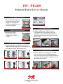
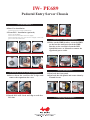
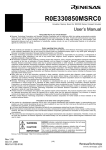
IW- PE689
Pedestal Entry Server Chassis
(Please read the following steps to assemble)
Please note that the pictures in this installation
guide are for your reference only, and they
may vary from the actual product.
Installation Guide
= Opening the Chassis =
1.Remove the Side Covers
Unscrew the Thumb screws and remove both side covers.
2.Remove the Front Panel
Unlock the locking tabs and remove the front panel.
IW- PE689
Pedestal Entry Server Chassis
= Power Supply Installation =
3.Insert the power supply to
the chassis with the power
supply fan facing down.
Use the mounting screws to
secure the position.
C
NC
NO
When the side cover
is opened.
C
NC
NO
When the side cover
is closed.
Intrusion Switch Header
= Motherboard Installation =
4.Please follow M/B
Installation Guide to
connect power cables
to M/B.
= 5.25 ODD Installation =
6.Pull the “ODD Secure Clips”, put the
5.25”optical drive in and then press the
clips.Refer from the M/B Quick Reference
and Manual to connect the signal cable and
power cable.
= Front I/O Wires Installation =
5.Connect all cables to M/B. (Included USB,
HDD LED, HD Audio, Power Switch, Power
LED, Reset Switch, Intrusion switch).
(Brown)
+
(white)
-
(Blue)
+
(white)
-
(Blue)
+
(white)
-
(Red)
+
(white)
-
(Orange)
+
(white)
-
Front Panel Header
VCC1
(RED)
D1(WHITE)
D1+
(GREEN)
1
3
5
GND
(BLACK)
7
NC
9
AUD_GND
(BLACK)
1
2
MIC
(BROWN)
AUD_GND
(BLACK)
3
4
MIC_BIAS
(ORANGE)
FP_RET_R
(YELLOW)
5
6
FP_OUT_R
(GREEN)
KEY
8
AUD_VCC
(RED)
FP_RET_L
(BLUE)
9 10
FP_OUT_L
(PURPLE / WHITE)
AC’97 Audio Header
2
VCC2
(RED)
AUD_GND
(BLACK)
1
2
MIC
(BROWN)
4
D2(WHITE)
AUD_GND
(BLACK)
3
4
MIC_BIAS
(ORANGE)
6
D2+
(GREEN)
FP_RET_R
(YELLOW)
5
6
FP_OUT_R
(GREEN)
8
GND
(BLACK)
KEY
8
AUD_VCC
(RED)
FP_RET_L
(BLUE)
9 10
KEY
USB Header
FP_OUT_L
(PURPLE / WHITE)
HD AUDIO Header
= 3.5” Floppy Installation =
7.Pull the FDD Secure Clips, push the FDD
Lock to the left, insert the FDD and press
down the clips. Refer from the M/B Guideline
to connect the signal cable, and then connect
the output power cable.
IW- PE689
Pedestal Entry Server Chassis
= FAN Installation =
8.Rear Fan installation
Connect the power cord to the Motherboard.
9.Front FAN Installation (optional)
Unscrew the fan holder.
Put the fan on the fan holder and screw it tightly.
Put the fan holder into server case and screw it tightly. Connect the
power cord to the motherboard.
= Internal 3.5” HDD Installation =
12.Take out the HDD bracket, screw the HDD
on the bracket and insert back the HDD
Bracket to the case.Refer from the M/B
Quick Reference or Manual to connect the
signal and power cable.
= Add-On (PCI/AGP) Card Installation =
10.P ress down the tool-free PCI clips and
remove the expansion slot cover
11.Install PCI/AGP Card and clip on tool-free
I/O slots
= Panel Installation =
13.Put back the front panel.
14.Put back the side panels and secure them by
Thumb Screws
= Completing Installation =