1
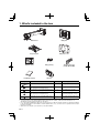
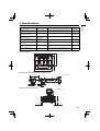
ENGLISH
WALL MOUNT BRACKET
MODEL
BR-380WM
The warning marks shown below are used throughout this installation manual to prevent personal injury or property
damage. Make sure you understand these warnings when reading this installtion manual.
Warning
This symbol indicates information
that, if ignored, could possibly result
in personal injury or even death due
to incorrect handling.
Symbol indicating an action that must not be
done
Caution
This symbol indicates information
that, if ignored, could possibly result
in personal injury or physical damage
due to incorrect handling.
Symbol indicating an action that should be
done
ESPAÑOL
Warning
ITALIANO
Safety precautions
DEUTSCH
FRANÇAIS
Installation Manual
The wall mount bracket is designed specially for mounting a projector to a wall.
If anything other than a projector is mounted, the weight may result in damage. If the wall mount
bracket falls, it could cause personal injury or property damage.
The installation work (wall mounting) should be performed by specialists who have technical
knowledge and ability.
Incomplete or incorrect installation could cause the wall mount bracket to fall and cause personal
injury or property damage. Contact the customer support office listed on the Mitsubishi Projector
Contact List in the User Manual for your projector when installing the wall mount bracket.
Follow the instruction in this manual when installing the wall mount bracket.
If the instructions are not followed, the wall mount bracket may fall, resulting in personal injury or an
accident.
Handle the power cord carefully.
Incorrect handling may cause fire or electric shock. Observe the following precautions when handling:
• Do not handle the power plug with wet hands.
• Do not use a power cord that is damaged or modified.
• Do not pull the power cord with too much force when routing the cable through the rail bracket.
PORTUGUÊS
When you mount the projector on the wall with the wall mount bracket, the wall requires
enough strength to hold the projector and the wall mount bracket. Confirm the mass of the
projector and the wall mount bracket before installation, and maintain the strength of the
wall. If the wall is not strong enough, reinforce the wall before installation.
Do not install the wall mount bracket in a place where it might be subjected to vibration or
shock.
Vibration or shock could cause damage to the projector or mounting surface. It could also cause the
wall mount bracket or projector to fall and cause personal injury or property damage.
Install the wall mount bracket so that it can sufficiently support the mass of the projector and
wall mount bracket, and resist any horizontal vibration. Use M8 nuts and bolts.
Nuts and bolts smaller than M8 could cause the wall mount bracket to fall. Mitsubishi takes no
responsibility for any damage or injury caused by incorrect installation.
EN-1
Safety precautions
Warning
The installation work should be performed by at least two qualified service personnel. If you
need to loosen any screws during installation, be careful not to drop the wall mount bracket.
If the wall mount bracket or projector falls, it could cause personal injury or property damage.
Inspect the wall mount bracket on a regular basis to ensure there are no broken parts or
loose screws. If there are any broken parts, stop using the wall mount bracket immediately.
If the wall mount bracket or projector falls, it could cause personal injury or property damage.
Never modify the wall mount bracket.
Do not hang on the wall mount bracket or hang a heavy object on the wall mount bracket.
If the projector or wall mount bracket falls, it could cause personal injury or property damage.
Tighten all screws firmly after adjustment.
If the screws are not tightened firmly, the projector or wall mount bracket may fall and cause personal
injury or property damage.
Never loosen the bolts and nuts after installation. Confirm that the screws have not become
loose on a regular basis. If you find any loose screws, tighten them firmly.
If the screws are not tightened firmly, the projector or wall mount bracket may fall and cause personal
injury or property damage.
Caution
Do not install the wall mount bracket in a location where the operating temperature for your
projector model may be exceeded.
Such an environment may damage the projector.
Install the wall mount bracket in a place free from excessive dust and humidity to prevent the
lens or optical components from becoming dirty.
Do not use excessive force when adjusting the wall mount bracket.
The wall mount bracket may break, resulting in personal injury.
Place to install the wall mount bracket
• Carry out the power supply wiring work for the installation location of the wall mount bracket in advance.
• Install the projector away from other electric devices such as fluorescent lights or air conditioners. Some kinds of
fluorescent lights could interfere with the remote control of the projector.
• It is recommended to keep connection cable length less than 20 meters to reduce external noise.
• Install the wall mount bracket in a place free from excessive dust and humidity to prevent the lens or optical
components from becoming dirty.
EN-2
ENGLISH
Installation
1
What’s included in the box
Page 4
2
Specifications
Page 5
3
Projection distance table
Page 6
4
Installation procedure
Pages 7 - 10
1. Install the wall plate on the wall.
2. Attach the rail bracket to the wall plate.
3. Adjust the length of the rail bracket.
4. Secure the projector plate to the projector.
5. Secure the projector to the rail bracket.
6. Connect the power cord and other cables to the projector.
5
Adjusting the projection screen
Pages 11 - 13
1. Turn on the projector.
2. Change the aspect ratio.
3. Display the test pattern.
4. Adjust the focus.
5. Fine adjust the projection screen size. (A to F)
6. After completing the adjustment, turn off the display of the test pattern.
A. Readjust the position of the rail bracket so that the rail bracket is
perpendicular to the wall.
B. Fine adjust the length of the rail bracket.
C. Adjust the horizontal position of the projector.
D. Adjust the forward/backward tilt of the projector.
E. Adjust the horizontal rotation of the projector.
F. Adjust the horizontal tilt of the projector.
6
Attaching the covers
Page 14
1. Attach the wall plate cover.
2. Attach the end cap (b) to the rail bracket.
3. Reinforce the installation strength, if necessary.
EN-3
1. What’s included in the box
Rail bracket
Wall plate
Projector plate
Wall plate cover
UP
CENTER
OF SCREEN
Template sheet
Fixing plate (2)
Installation manual
End cap
Shape
Name
Hexagon wrenches
(for M5, M6 and M8)
Quantity
Application
M8 x 70 mm hexagon socket head cap bolt
2
For adjusting rail bracket angle
M8 x 20 mm hexagon socket head cap bolt
with spring washer and plain washer
2
For securing rail bracket
M6 x 14 mm cross-recessed pan head screw
with spring washer and plain washer
4
For installing projector plate
M4 x 10 mm cross-recessed pan head screw
with spring washer and plain washer
7
For installing the projector (3) and
for installing wall plate cover (4)
M3 x 8 mm cross-recessed pan head screw
with spring washer and plain washer
4
For securing projector plate and
fixing plates
• Use the bolts and screws supplied with the wall mount bracket to install it, as directed in this manual. Do not
substitute these bolts and screws with any other types.
• Use commercially available M8 x 50 mm anchors (at least 4) or 8 x 80 mm lag bolts (at least 4) to attach the wall plate
to the wall. Depending on the installation condition (wall thickness, etc.), use the anchors or lag bolts which are longer
than those specified.
• Gather the tools and parts you need before you begin installation.
EN-4
Item
Specification
Reference
page
Remark
Rail bracket mass
Approx. 9.5 kg
Wall plate (2.9 kg), projector plate (1.0 kg),
wall plate cover (0.7 kg)
Rail bracket forward/backward
slide adjustment range
380 mm (14.96 in.)
Refer to the
figure below.
Rail bracket vertical tilt
adjustment range
Upward: 6°
Downward: 2°
12
Horizontal slide adjustment
range
±35 mm (1.38 in.)
Refer to the
figure below.
Forward/backward tilt adjustment range
±7°
Fine adjustments possible with adjustment
dial
13
Horizontal rotation adjustment
range
±7°
Fine adjustments possible with adjustment
dial
13
Horizontal tilt adjustment
range
±5°
Fine adjustments possible with adjustment
dial
13
Wall plate dimension
200 (7.87)
300 (11.81)
350 (13.78)
250 (9.84)
(25 (0.98))
200 (7.87)
Unit: mm (in.)
Rail bracket forward/backward slide adjustment range
380 (14.96)
Unit: mm (in.)
Horizontal slide adjustment range
Unit: mm (in.)
35 (1.38)
35 (1.38)
EN-5
ENGLISH
2. Specifications
3. Projection distance table
Refer to the table below and install the wall mount bracket and projector to project images at an appropriate size on the
projection surface.
• The values are only rough estimates.
A
242.2 mm
(9.54 in.)
55 mm (2.17 in.)
(Offset value for the position of the center of the screen
and the center of the wall plate)
Projection surface
L
SH
SZ
Center line of the
screen
0.13 m (5.12 in.) (Thickness of the standard white board)
SW
Lens
WXGA
16
4
XGA
10
SZ
3
Center line of the projector
For XD360U-EST (XGA)
Screen size
SZ: diagonal size
inch
60
65
70
75
80
SW: width
cm
122
132
142
152
163
inch
48.03
51.97
55.91
59.84
64.17
SH: height
cm
91
99
107
114
122
inch
35.83
38.98
42.13
44.88
48.03
L: projection distance
m
0.56
0.61
0.67
0.72
0.77
inch
22.05
24.02
26.38
28.35
30.31
A: distance between
projection screen and
wall plate
cm
inch
28.5
11.22
29.9
11.77
30.8
12.13
31.9
12.56
33.0
12.99
For WD380U-EST (WXGA)
Screen size
SZ: diagonal size
inch
70
75
80
85
90
95
EN-6
SW: width
cm
151
162
172
183
194
205
inch
59.45
63.78
67.72
72.05
76.38
80.71
SH: height
cm
94
101
108
114
121
128
inch
37.01
39.76
42.52
44.88
47.64
50.39
L: projection distance
m
0.56
0.60
0.64
0.69
0.73
0.77
inch
22.05
23.62
25.20
27.17
28.74
30.31
A: distance between
projection screen and
wall plate
cm
inch
26.6
10.47
27.4
10.79
28.3
11.14
29.1
11.46
29.9
11.77
30.8
12.13
1. Install the wall plate on the wall.
(1) Determine the template sheet position.
• From the projection distance table, confirm the screen size (SZ) and the distance between the projection
surface and wall plate (A).
• Align the vertical center line (a) of the CENTER OF SCREEN of the template sheet with the vertical center
line of the projection surface.
Confirm where the beams are within the wall, and shift the position left or right as necessary.
(The position can be shifted horizontally left or right from the center line of the projection surface by up to 35
mm.)
• Align the horizontal line (b) of the template sheet with the distance of A.
55 mm (2.17 in.)
Offset value for the position of the center of
the screen and the center of the wall plate
(a)
UP
CENTER
OF SCREEN
35 mm (1.38 in.)
35 mm (1.38 in.)
A
(b)
Template sheet
Center of the lens
Screen
Projection surface
SZ
Center of the screen
(2) Attach the template sheet to the wall.
EN-7
ENGLISH
4. Installation procedure
4. Installation procedure
(3) Make mounting holes in the wall in the required locations.
• The wall plate needs to be secured by commercially available anchors or lag bolts in the following places. It
is recommended that the wall plate be secured in at least four places.
Four mounting holes
Make holes at the locations indicated by
Five mounting holes
or
.
Make holes at the locations indicated by
UP
or
.
UP
CENTER
OF SCREEN
CENTER
OF SCREEN
(4) Remove the template sheet and mount the wall plate on the wall.
Warning
• When you mount the projector on the wall with the wall mount bracket, the wall needs to be strong enough to
hold the projector and the wall mount bracket. Confirm the mass of the projector and the wall mount bracket
before installation, and maintain the strength of the wall. If the wall is not strong enough, reinforce the wall before
installation.
• Install the wall mount bracket so that it can sufficiently support the mass of the projector and setting late, and
resist any horizontal vibration. Use M8 nuts and bolts. Nuts and bolts smaller than M8 could cause the wall mount
bracket to fall.
• We take no responsibility for any damage or injury caused by incorrect installation.
2. Attach the rail bracket to the wall plate.
(1) Hang the rail bracket hook (c) onto the wall plate bar.
(c)
(d)
(e) M8 x 20 mm hexagon socket
head cap bolt (2)
(f) M8 x 70 mm hexagon socket
head cap bolt (2)
(f)
(e)
(2) Pass the cables through the slider of the rail bracket. (d)
Caution
Take care not to trap the cables between the rail bracket and wall plate.
(3) Tighten the bolts (e) and bolts (f) supplied with the wall mount bracket so that the wall
mount bracket becomes vertical against the wall.
EN-8
(1) Loosen the four screws (g) and four screws (h) and pull out the slider to the appropriate
scale marking for the projection screen size (i).
• The scale is marked assuming that the standard white board with 0.13 m thickness is used. When the
thickness of the board is other than 0.13 m, fine adjust the length of the rail bracket later. (See page 12.)
(2) Tighten the four screws (g) and four screws (h).
(g)
(h)
65
75
60
70
h
A inc h
XG
inc
GA
WX
(i)
Example: when the projection screen size is XGA70.
XGA inch
WXGA inch
60
70
65
75
70
80
75
85
80
90
95
EN-9
ENGLISH
3. Adjust the length of the rail bracket.
4. Installation procedure
4. Secure the projector plate to the projector.
(1) Loosen the adjustment feet of the projector (k), attach the projector plate (m) to the
projector, and then secure the projector plate to the projector by tightening the supplied
screws (n).
(2) Tighten the adjustment feet (k).
(n)
(m)
(n) M4 x 10 mm cross-recessed pan
head screw (3)
(k)
5. Secure the projector to the rail bracket.
(1) Hang the projector with the assembled projector plate to the hook of the rail bracket. (p)
(2) Put the fixing plates (r) through the pin of the rail bracket and secure them with the
supplied screws (s).
(3) Secure the plates with the supplied screws (t).
(s)
(r)
(t)
(s) M3 x 8 mm cross-recessed pan
head screw (4)
(p)
(t) M6 x 14 mm cross-recessed pan
head screw (4)
6. Connect the power cord and other cables to the projector.
EN-10
5. Adjusting the projection screen
ENGLISH
When the projected image extends off screen or distorts, adjust the screen by the following procedures.
1. Turn on the projector.
Using control panel
Using remote control
ON
STANDBY
ASPECT
MAGNIFY
UP
VOL
KEYSTONE
DOWN
3D
AUTO
POSITION
MENU
ENTER
AV
MUTE
FREEZE
2. Change the aspect ratio.
(1) Press the ASPECT button on the remote control to change to the appropriate aspect
ratio.
• Every time the ASPECT button is pressed, the aspect mode changes from Normal to 16:9, to Full, and back
to Normal.
ON
STANDBY
ASPECT
MAGNIFY
UP
VOL
KEYSTONE
DOWN
3D
AUTO
POSITION
MENU
ENTER
AV
MUTE
FREEZE
3. Display the test pattern.
Adjust the focus by using an image output from a computer. Or, adjust the focus by using
splash screen of the projector.
4. Adjust the focus.
Use the focus ring to adjust the focus.
5. Fine adjust the projection screen size. (A to F)
Fine adjust the projection screen size by the methods A to F on the following pages.
6. After completing the adjustment, turn off the display of the test pattern.
EN-11
5. Adjusting the projection screen
A. Readjust the position of the rail bracket so that the rail bracket is perpendicular to the wall.
(1) Loosen the two bolts (a) and the two bolts (b) to readjust the position of the rail bracket
so that the rail bracket is perpendicular to the wall.
(2) After completing the adjstment, firmly tighten the bolts loosened in step (1).
(a)
(b)
B. Fine adjust the length of the rail bracket.
(1) Loosen the four screws (c) and the four screws (d) to fine adjust the length of the rail
bracket.
(2) After completing the adjstment, firmly tighten the screws loosened in step (1).
(c)
(d)
C. Adjust the horizontal position of the projector.
(1) Loosen the four screws (e) to adjust the horizontal position of the projector.
(2) After completing the adjstment, firmly tighten the screws loosened in step (1).
(e)
EN-12
ENGLISH
D. Adjust the forward/backward tilt of the projector.
(1) Loosen two hexagon bolts (f). (Left and right)
(2) Turn the adjustment dial (g) to adjust the forward/backward tilt.
(3) After you finish making the adjustment, firmly tighten the bolts (f).
(f)
(g)
E. Adjust the horizontal rotation of the projector.
(1) Loosen the two hexagon bolts (h). (Front and back)
(2) Turn the adjustment dial (k) to adjust the horizontal rotation.
(3) After you finish making the adjustment, firmly tighten the bolts (h).
(h)
(k)
F. Adjust the horizontal tilt of the projector.
(1) Loosen the two hexagon bolts (m). (Front and back)
(2) Turn the adjustment dial (n) to adjust the horizontal tilt.
(3) After you finish making the adjustment, firmly tighten the bolts (m).
(m)
(n)
EN-13
6. Attaching the covers
1. Attach the wall plate cover.
Secure the wall plate cover with the supplied screws (a).
• Depending on how the cables are wired, you may need to cut out parts of the wall plate cover to allow the
cables to be passed through it.
(a)
(c)
(b)
(a) M4 x 10 mm cross-recessed pan
head screw (4)
2. Attach the end cap (b) to the rail bracket.
3. Reinforce the installation strength, if necessary.
When the projector or the projected image vibrates depending on the usage environment,
use a commercially available wire or the like to reinforce the installation strength. (c)
7.
Warning
• Never loosen the bolts and nuts after installation. Confirm that the screws have not become loose on a regular basis.
If you find any loose screws, tighten them firmly. If the screws are not tightened firmly, the projector or wall mount
bracket may fall and cause personal injury or property damage.
• Do not hang on the wall mount bracket or hang a heavy object on the wall mount bracket. If the projector or wall
mount bracket falls, it could cause personal injury or property damage.
8. Attaching a security cable
You can use a commercially available theft-prevention wire lock to secure the projector to a post or other object to
prevent someone from taking it.
For details on how to lock the wire lock, refer to the user manual supplied with the wire lock.
EN-14