1
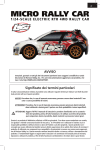
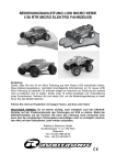
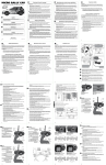
HIGH H IGH ROLLER 1/10-SCALE ELECTRIC RTR LIFTED TRUCK LOSB0103 1/10 HIGHroller RTR Not responsible for errors. All prices subject to change without notice. Losi, a Division of Horizon Hobby, Inc. 1 Table of Contents NOTICE All instructions, warranties and other collateral documents are subject to change at the sole discretion of Horizon Hobby, Inc. Forup-to-dateproductliterature,visit http://WWW.LOSI.COM/SUPPORT Introduction .................................................................................................2 SafetyPrecautions......................................................................................3 Battery/Charging ........................................................................................3 SuppliedandRequiredEquipment .....................................................4 Technical Overview................................................................................5-7 ESCOverview/Troubleshooting ............................................................8 TransmitterBatteryInstallation .............................................................9 VehicleBatteryInstallation ...................................................................10 Quick Start ..................................................................................................11 Losi 27MHz AM Radio System ....................................................... 12-13 Drivingthe1/10HIGHroller ..................................................................14 Tuning,AdjustingandMaintainingthe1/10HIGHroller .... 15-18 Troubleshootingyour1/10HIGHroller .............................................19 Warranty Information ...................................................................... 20-21 RCTerminology .........................................................................................22 PartsListing ......................................................................................... 23-24 Optional parts Listing ...................................................................... 24-25 ExplodedViews .................................................................................. 26-29 Stock Setup Sheet ....................................................................................30 BlankSetupSheet ....................................................................................31 Meaning of Special Language Thefollowingtermsareusedthroughouttheproduct literature to indicate various levels of potential harm when operatingthisproduct: NOTICE:Procedures,whichifnotproperlyfollowed,createa possibility of physical property damage AND a little or no possibility of injury. WARNING:Procedures,whichifnotproperlyfollowed,create the probability of property damage, collateral damage, and serious injury OR create a high probability of superficial injury. Safety Warnings and Precautions Introduction ThankyouforpurchasingtheLosi®1/10HIGHroller.Weare confident you will be satisfied with the performance of this durable and resilient vehicle. In the following pages you will find all the information you will needtosetupaswellasoperateyournew1/10HIGHrollerto its full potential. ThisisasophisticatedhobbyproductandNOTatoy.Itmustbe operated with caution and common sense and requires some basicmechanicalability.FailuretooperatethisProductina safe and responsible manner could result in injury or damage totheproductorotherproperty.Thisproductisnotintended for use by children without direct adult supervision. Do not attempt disassemble, use with incompatible components or augment product in any way without the approval of Horizon Hobby,Inc.Thismanualcontainsinstructionsforsafety, operation and maintenance. It is essential to read and follow all the instructions and warnings in the manual, prior to assembly, setup or use, in order to operate correctly and avoid damage or serious injury. If you are an experienced RC hobbyist, or new to RC vehicles, it will benefit you to read all enclosed information. Register your Losi Product Online Registeryour1/10HIGHrollernowandbethefirsttofindout about the latest options parts, product updates and more. Log on to WWW.LOSI.COM/REGISTER and follow the product registration link to stay connected. Losi/Horizon Support If you have any questions concerning setup or operation of your1/10HIGHroller,contacttheappropriateHorizonProduct Support office. Hours: MondaythruFridayfrom8:00amCSTto5:00pmCST Getting Ready Thoroughlyreadalltheenclosedmaterial,precautionsand follow instructions to avoid damaging your new RC vehicle. If you choose to not follow these steps or instructions, it will be considered negligence. •Readallinstructionsprovidedbythemanufacturerofthe batteries prior to use. •Neverleavethebatteryandchargerunattendedduringuse. •Neverallowminorstochargebatterypackswithoutadult supervision. •Neverattempttochargedeadordamagedbatteries. •Neverchargeabatteryifthecablehasbeenpinchedor shorted. •Neverallowbatteriesorchargertocomeintocontactwith moisture at any time •Neverchargebatteriesinextrememlyhotorcoldplaces (recommendedbetween50--80degreesFahrenheit)or place in direct sunlight. •AlwaysuseonlyNiMHorNiCdrechargeablebatteries. Chargers cannot charge batteries such as “heavy duty,” “Alkaline battery,” or “Mercury battery.” •Alwaysconnectthepositiveredlead(+)andnegativeblack lead(-)terminalsofthebatterytothechargerterminals correctly. •Alwaysdisconnectthebatteryandchargerafterchargingand let them cool between charges. •Alwaysinspectthebatterybeforecharging. •Alwaysmakesureyouknowthespecificationsofthebattery to be charged or discharged to ensure it meets the requirements of this charger. •Neverconnectmorethanonebatterypacktothechargerata time. •Alwaysconstantlymonitorthetemperatureofthebattery pack while charging. •Alwaysendthechargingprocessifthechargerorbattery becomes hot to the touch or starts to change form during the charge process. We hope you operate this RC model in a safe, reasonable and cautious fashion in order to enjoy your vehicle. Should you operate this vehicle without a cautious and reasonable approach it may result in serious injury and/or property damage. Only you can control and make certain that safety precautions and instructions are followed. General: • • • • • Introduction WARNING:ReadtheENTIREinstructionmanualtobecome familiar with the features of the product before operating.Failuretooperatetheproductcorrectly can result in damage to the product, personal property and cause serious injury. Batteries and Charging: THISPRODUCTISSUITABLEFORCHILDREN14YEARS OROVER.THISPRODUCTISNOTATOY.Thisproductis not intended for use by children without direct adult supervision. ThisRCvehicleisnotintendedforuseonpublichighways or roads. Avoidanareathathasmanypedestriansorcrowds of people. Keepinmindthatthisvehicleisradiocontrolledand can experience moments of radio loss or interference, so provide for a margin of error at all times. Pleasebeawarethatthemotorandbatteriesofthis RCvehiclewillgetHOTduringeachuse.Becarefulnot to burn yourself. Electronic Speed Control (ESC): • • • • • • • • Readallsafetyprecautionspriortoeachuse. Neverleavethevehicle/ESCunsupervisedwhileitis switched on, in use or connected to a power source. If there is a short circuit or product defect, it could result in fire. Ifthereareexposedwires,donotusetheESCuntilyou have installed shrink-wrap or replaced the wire. DisconnectthebatteryfromtheESCafteruse. TheESCisnotwaterproofandshouldnotbeexposed to moisture. Do not attempt to use LiPo batteries or more than 6-cells NiMH batteries; doing so will damage the ESC and could result in fire. AlwaysturnonthetransmitterfirstthentheESCto prevent an out-of-control vehicle. WhensettingyourElectronicSpeedController: º Pleasedisconnectmotororremovethepiniongear duringESCsetuporcalibrationfunctions. º Keeplooseclothing,hair,glovesandfingersaway from moving parts at all times. º Rubber tires can cause severe injury if there is a failure while running the vehicle while on a stand or whenbeingheld.Ensurerubbertiresaresecurely mounted to the rims and if not, re-glue them and check them often for security. When charging NiMH batteries, select a charger to meet your requirements. Chargers can be of two primary types for theirsourceofpower;a100-240Vwallcharger,oronewhich requiresa12Vpowersupply.Followthechargermanufacturer’s instructions and precautions during each use. Ifafterreviewofthismanualandpriortorunningyour1/10 HIGHroller,youdeterminethisRCvehicleisnotwhatyou want—DONOTproceedandDONOTrunthe1/10HIGHroller. Ifthe1/10HIGHrollerhasbeenrun,yourlocalhobbyshopwill not be able to process a return or accept it for exchange. 2 3 Supplied and Required Equipment Eight(8)AAbatteries The Losi 1/10 HIGHroller Overview Supplied tools: NiMH battery charger with automatic “peak detection” recommended. 2-Way wrench Two(2)HexWrenches(Lshaped) 1/16and3/32 DYN4044VisionPeak™2AC/DCCharger FlatTurnbuckleWrench Recommended Accessories: - - - - Hobby grade knife CAglue(LOSA7880orLOSA7881) Needle nose pliers Side cutting pliers Double-sidedtape(LOSA4004) SafetyGoggles Soldering iron Required Equipment: ASix(6)cellNiMHbatterypack. Using your charger: If you do not yet have a charger, a peak detecting charger will provide the performance required and take care of your expensive batteries. A popular choice for a charger would be a peak detection charger that can be plugged into a household AC wall socket. Thepeakdetectionportionofthechargermonitorsthebattery charging and automatically shuts off upon full charge. Otherpeakdetectionchargersrequirea12Vpowersourceto chargeyourbatteries.Youwouldneedtouseorpurchasea hobbygrade12Vpowersupplybeforecharging. Vehicle Battery (6-Cell7.2V“StickPack”) LOSB9900 If you are going to be using a charger other than a peak detection charger it is important to have your battery fully dischargedpriortorecharging.Manyofthesehavea15–20 minute timer that allows you to set the amount of charge time. If the battery was not fully discharged from prior use, you can potentially overcharge your battery pack. 4 5 The Losi 27MHz AM Radio System Overview 6 1/10 HIGHroller Electronics System Overview 7 MSC 12RB 12T Fwd/Rev ESC Adjusting the Transmitter Features • High-power FET control with proportional forward and reverse. • High-frequency design delivers smooth speed transition. 1. Set the “throttle reversing” switch to the NORMAL position. 2. Set the “throttle trim” to the CENTER position. • Thermal Overload Protection prevents damage due to overcurrent conditions. • Pre-wired with Tamiya-style battery plug and bullet-style motor connectors. • Designed to operate with stock motors (12 turns or higher). Installing Batteries: Transmitter Removethebatterycoverfromthebottomofthetransmitterbyslidingitawayfromthebaseofthehandle.Installtheeight(8)AAsize batteries into the base, noting polarity when inserting each battery. Speed Control Programming NOTE : While in the programming mode, no power is applied to the motor. 1. Turn on the transmitter’s power switch. (Be sure the transmitter batteries are fully charged). 2. Turn the ESC switch on. 3. Press and release the setup button. The red and green LEDs will light. 4. Move the throttle to the full throttle position and press the programming button. The green LED will remain lit and the red LED will go out. (If the ESC does not sense throttle movement in 3 seconds by the transmitter, it will exit the programming mode and you will have to begin again.) 5. Now move the throttle to full reverse and press the programming button. The red LED will glow and the green LED will go out. 6. Return the throttle to neutral and press the programming button. The green LED will glow and the red LED will go out, indicating programming is complete. During normal operation, the green LED indicates neutral and the red LED indicates full forward and full reverse. • Push-button programming makes setup a breeze. Operation ....................................... Proportional forward, proportional reverse with braking delay Input Voltage ..................................4-cell (4.8 volts) to 6-cell (7.2 volts) DC Peak Current .................................. 900 amperes Continuous Current ........................ 46 amperes Full-On Resistance ......................... 0.0014 ohms Frequency ...................................... 2kHz BEC output ..................................... 4.8V DC, 1 amp max Overload Protection........................ Thermal Dimensions .................................... 1.25 x 1.02 x .888 in (38.6mm x 26.2mm x 22.5mm) Weight ............................................ 1.2 oz (34 g) Selecting Forward Only or Forward/Reverse Mode The MSC 12RB has 2 modes: Forward Only mode and Foward and Reverse mode. The Forward Only mode can be selected for racing purposes. When the ESC is powered on, the LED will flash for 2 seconds; the color of the LED indicates which mode the ESC is operating in: Forward and Reverse Mode–the Green LED will flash Forward Only Mode–the Red LED will flash. To change modes, push the set button and turn on the ESC. The LED will flash, indicating the new mode has been selected. Note the color of the LED to determine the mode of your ESC. Connecting the Battery The MSC 12RB comes pre-wired with a Tamiya-style connector, compatible with most battery packs. Use battery packs from 4-cell (4.8-volt) to 6-cell (7.2-volt) sub-C size battery packs. 1. Be sure the on/off switch is in the “off” position. 2. Connect a fully charged battery pack to the speed control’s battery connector. Transmitterwithbatteries Troubleshooting Guide Symptom Solution Steering servo operates but the motor does not run Programming is not complete. Reprogram the ESC by following the programming instructions. Speed control connected to receiver incorrectly. Motor defective. Test motor independently, repair or replace as needed. Low batteries. Charge as needed. Overload Protection enabled. Check motor and connections. Steering and motor do not function Receiver wired incorrectly. Check polarity and orientation of control plugs. Batteries discharged. Recharge or replace. Full speed not attainable Transmitter adjusted improperly. ESC programmed incorrectly. Reprogram. Motor slows but will not stop Throttle trim may be set improperly. ESC program does not match transmitter. Reprogram ESC. Reduced radio range/interference Motor capacitors broken/missing. Repair or replace. Motor noise. Move receiver further away from ESC, motor and wiring. Transmitter batteries low. Replace batteries. 8 Reinstall the battery cover by sliding it back on the handle base. 9 Battery Pack(s) Quick Start Toinstallthebatterypackremovethebatteryhold-downstrapbyremovingtheclipfromthefrontmountingboss,andthen,while lifting the strap, pulling forward in one motion. Note: Please read the entire manual to gain a full understanding of the 1/10 HIGHroller vehicle, fine-tuning the setup and performing maintenance. 1. R eadthesafetyprecautionsfoundonpage3.Thisisimportantforyoursafetyand prevention of personal injury. 2. C hargethebatterypackyouhavechosen(NOTINCLUDED).Refertothe manufacturer’ssuppliedinstructionsforbatterycharginginformation. 3. I nstalltheAAbatteries(NOTINCLUDED)intotheLosi27MHzAMtransmitter(seepage 9).Usealkalineorrechargeablebatteriesonly. 4. I nstallthebatterypack(seepreviouspage).Thebatterypackshouldbefullycharged before installation. 5.Turnonthetransmitterandthenthevehicle.Itisagoodpracticeto turn on the transmitter before the vehicle and turn it off after the vehicle has been turned off. After you have inserted the fully charged battery pack reinstall the battery hold-down strap. 6. Checksteering(seepage12).Verifythattheservoisfunctioningproperly. 7. Drivingthe1/10HIGHroller(seepage14). 8. P erformingmaintenanceofthe1/10HIGHroller.RefertoTuning,Adjustingand Maintenanceofthe1/10HIGHrolleronpage15. Notice that the battery hold-down has a flat side while the other side has strengthening ribs; the rib side should be facing down to the battery. Insert on an angle into the rear support, and then down on the front pin and secure it with the previously removed clip. 10 11 Losi 27MHz AM Radio System Receiver Thereisnoadjustmentrequiredofthereceiver.Pleasenotethedifferentslotsforconnection. The Radio System ThefollowingisanoverviewofthevariousfunctionsandadjustmentsfoundonyourLosi/HIGHrollerradiosystem.Sincethe HIGHrolleroperatesonaradiosignal,itisimportantforyoutoreadandunderstandaboutallofthesefunctionsbeforedrivingthe model. The Transmitter Steering Rate:Adjustsamountfrontwheelsmovewhenthe steering wheel is turned left and right. Steering Wheel:Controlsdirection(left/right)ofthemodel. Throttle Trigger:Controlsspeedanddirection(forward/ reverse)ofthemodel. ST. REV:Reversesthefunctionofthesteeringwhenthe wheel is turned left or right. Antenna:Transmitssignaltothemodel. TH. REV:Reversesthefunctionofthespeedcontrolwhen pulled back or pushed forward. On/Off Switch:Turnsthepoweron/offforthetransmitter. Indicator Lights:Green(right)lightindicatesadequate batterypower.Red(left)indicatessignalstrength. Bottom Cover:Coversandholdsthebatteriesthatpower the transmitter. ST. Trim:Adjuststhe“handsoff”directionofthemodel. Transmitter Crystal:Determinesfrequency/channelyou transmiton.Thereceivermusthaveamatchingfrequency/ channel to operate. TH. Trim:Adjuststhemotorspeedtostopatneutral. Changing Frequencies/Channels TheHIGHrollerradiooperateson27MHzAMandhas6differentfrequencies/channelsavailable.TheHIGHrollerradioisequipped withchangeablecrystalsthatallowyoutochangethefrequency/channelyouoperateon.Thisisespeciallyusefulwhenyouwant torunagroupofLosiHIGHrollersatthesametime.Whenchangingcrystals/channels,youmustalwaysreplacethecrystalsasa matchedsetwithoneeachgoinginboththetransmitterandthereceiverinthetruck.Eachofthe6differentchannelsarenumbered andcolor-coded.Eachsetincludesauniquecrystalforthereceivermarked(Rx)andonefromthetransmittermarked(Tx).Tochange thecrystals,gentlypullthemout.Then,lineupthetwopinsofeachnewcrystalwithitssocket.Carefullypushthemintoplace.DO NOTforcethemasdamagecanoccur.Iftheydonotslideintothesocketeasily,checkforbentormisalignedpins. Channel1 Brown26.995MHz (LOSB1094) Channel2 Red27.045MHz (LOSB1095) Channel3 Orange27.095MHz (LOSB1096) Channel4 Yellow27.145MHz (LOSB1097) Channel5 Green27.195MHz (LOSB1098) Channel6 Blue27.255MHz (LOSB1099) Factory Settings of Radio/ESC TheElectronicSpeedControlwascalibratedtogetherwiththeradiosystematthefactory.Whenyouturnonandrunthe1/10 HIGHrollerforthefirsttimeyoumayberequiredtoslightlyadjusttheThrottleTrim.Ifthevehiclecreepsinreverseorinforward, makeafineadjustmenttotheThrottleTrimknobonthetransmitter.Sometimesthebumpsandbouncesoftransportationcan slightly alter the settings. 12 13 Driving the 1/10 HIGHroller Howyoudriveyour1/10HIGHrollerwillalsoaffectyourrun times. If you are performing runs, going from a standstill to full speed repeatedly, you are asking a lot from your batteries and electronics. Hard acceleration draws a lot of current from any battery and will lead to shortened run time. Pleasenotethefollowingprecautionsbeforerunning your1/10HIGHroller. • TheElectronicsinthisvehiclearenotwaterproofandyou must avoid running the vehicle in or through standing water, wet grass, mud or snow. • Thisvehicleisquick: o Do not run the vehicle if it will be out of sight for any amount of time. o Do not drive your vehicle near a crowd of people. • Performacheckofthevehiclebeforegoingouttorunit. o Ensurethetiresarenotcomingofftherims. o Generallycheckthevehicleforitemssuchasa loose wheel nut, or anything loose on the steering assembly.Thevibrationsofrunningoff-roadtendto loosen screws and nuts. • Becarefuldrivingwhenthebatteryisnearlydischargedor thecarisrunningslowly.Youcouldloseenoughpowerfor the receiver to shutdown and you may lose control. • Whendrivingthe1/10HIGHrollerbecautiousanduse common sense. • Ifyourvehiclegetscaughtorstuckdonotpullthethrottle ineitherforwardorreverse.ThiswilloverloadtheESC and/or motor resulting in damage to one or possibly both and is not covered by your warranty. • Afterrunningabatterypack,allowtheelectronicsseveral minutes to cool before running the next battery pack. If the bearings are dirty they will cause significant drag causing reduced run times and speed. Toimproveruntimesconsiderthefollowing: • Keepyourvehiclecleanandmaintained. • AllowmoreairflowtotheheatsinkoftheMSC12RBESC. • Changethegearingtoalowerratio,thiswillmakethe electronicsruncooler.Thiscanbeaccomplishedbyusing asmallerpiniongearthanthoseoriginallysupplied.(The 1/10HIGHrollercomeswitha12-toothpinionandan 90-toothspurgear.) • ChangetobatterypacksofhighermAhrating. • Isthechargeryou’reusingthebestatchargingyour batteries? Check with your local hobby dealer. Run time consideration for the 1/10 HIGHroller vehicle. ThesinglelargestfactorinruntimeisthecapacitymAhof yourbatterypack.ThelargerthemAhratingthemoreruntime you will experience. On the same note, the longer you run, the hotterthebatteryplugscanget.Pleasecheckthestandard plugs periodically. Tuning the Front End of the 1/10 HIGHroller Tuning, Adjusting & Maintaining the 1/10 HIGHroller Shock Location:The1/10HIGHrollerhasthreemounting locationsonthefrontshocktower.Thepositioncanbeeasily adjusted by simply moving the top of the shock to another hole.Thestandardlocation(middleholeonthetower)works best on most surfaces. Moving the top of the shock inward a holewillslowsteeringresponseandmakethe1/10HIGHroller smoother in bumps. Running the inside shock location on the armwillgivethe1/10HIGHrollermoresteeringintotheturn and less steering on corner exit. Running the shock location outside on the front arm will give you less overall steering into the turn and keep the front end flatter through the turn, makingthe1/10HIGHrollersmootherandeasiertodrive.This can be used on high-traction surfaces. Periodically examine your 1/10 HIGHroller for the following: • Keepyourvehiclecleanusingabrushtoremovedirt and dust. • Lookforcracksinthesuspensionarmsandother molded parts. • Checkthatthetiresarestillgluedtothewheels. • Checkthatallthewheelbearingsarecleanandlubricated. • Usingyourtools,attempttotightenallthescrewsand nuts. • Verifythatthecamberlinksandsteeringlinkageare not bent. • Checkthatthetoeandcambersettingsareasdesired and equal. • Removethegearcover. o Check the spur gear for wear. o Check the pinion gear. o Check the slipper pads for wear. • Taketheshocksoffthevehicleandcheck,especiallyifthey appear to be leaking as it is time to rebuild them. • Lookoverallthewiringandconnectionsforbarewireor any place which could lead to a short circuit. • VerifythattheESCissecurelymountedtothechassis. • Verifythereceiverisstillsecurelymountedtothechassis. • Turnontheradio.IftheGreenLEDisoffordim,replace the 8 AA batteries in the transmitter. Afteryoubecomefamiliarwithdrivingyour1/10HIGHroller, you may need to reset or make adjustments for better driving performance. Usingthesuppliedflatmetalturnbucklewrenchifyouneed toSHORTENanylinkonthe1/10HIGHroller,rotatethewrench towardstherearofthevehicle(clockwise).Ifyouneedto LENGTHENanylinkthenrotatethewrenchtowardsthefrontof thevehicle(counterclockwise). Static Camber:Thisreferstotheangleofthewheels/tires relativetothesurface(viewedfromeitherthefrontorback). Negative camber means that the top of the tire leans in toward thechassis.Positivecambermeansthetopofthetireleansout, away from the chassis. Camber can be precisely measured with aftermarket camber gauges, sold at local hobby shops. It can bemeasured(roughly)usinganysquare(totheground)object by checking the gap between the square edge and the top of thetire.Testinghasshownthat1degreeofnegativecamber is best for most track conditions. Increasing negative camber (intherangeof1-2degrees)willgenerallyincreasesteering. Decreasingnegativecamber(intherangeof0-1degree)will generallydecreasesteeringandthe1/10HIGHrollerwillfeel easiertodriveasaresult.Thisis,mostoften,averycritical adjustmentintuningyour1/10HIGHrollerthatcanbemade quickly and easily. Just as in a real car, alignment is an important factor in your vehicle’shandling.Whenyouarereadytomakeadjustments it is a good idea to have a flat work space to place your vehicle on.Thiswillenableyoutoeasilyandmorequicklymakeboth toe-inandcamberadjustments.Theseadjustmentsshouldbe set with the vehicle sitting at its normal ride height. Forexample:ifyouhavea4600mAhbatterypackyoucan expectclosetotwicetheruntimeofa2000mAhbatterypack. Theconditionofabatterypackisalsoanimportantfactorin both run time and speed. As batteries see more use they will degrade in performance and capacity. 14 15 Inboard Camber Location:The1/10HIGHrollerhasthree different inner locations with vertical adjustment for the front camber tie rod. In general, the lower or further out the inside position is, relative to the outside, the more camber gain (total camberchangethroughthetotalthrowofthesuspension)is present.Thisisanadjustmentthatisdifficulttomakeageneric statement for as it can have slightly different results on various conditions.Thefollowingisasummaryofhowthisadjustment willusuallyimpactthehandlingofthe1/10HIGHroller.A longerfrontcamberlinkwillusuallymakethe1/10HIGHroller feelstiffer.Thiswillhelpkeepthe1/10HIGHrollerflatterwith lessroll,butcanmakethe1/10HIGHrollerhandleworsein bumpyconditions,italsowillmakethe1/10HIGHrollereasier to drive. A shorter front camber link will result in more front end roll, which will provide more steering on tighter turns with thelossofsomestability.Youwillalsolosesomehigh-speed steeringbutmightgainsomemoresteeringresponse.Too shortofafrontlinkmaymakethe1/10HIGHrollerfeel“twitchy” or “wandery” meaning that it may be difficult to drive straight at high speed. Outboard Camber Location:Inadditiontotheinboard camberlocation,the1/10HIGHrolleralsoprovidestwo outboardmountingoptions.Theouterlocationhelpsthe1/10 HIGHrollerstaytighterinturnswithamoreprecisesteering feel. Moving the link to the inner hole will make the steering reactslightlyslowerandsteersmoother.Theadvantagetothe inner hole is that it can increase on-power steering and help the 1/10HIGHrollergetthroughbumpsbetter. Toe-In/Out:Thisistheparallelrelationshipofthefronttiresto oneanother.Toe-in/outadjustmentsaremadebychangingthe overalllengthofthesteeringtierods.Toe-in(thefrontofthe tirespointinward,toapointinfrontofthefrontaxle)willmake the1/10HIGHrollerreactalittleslower,buthavemoresteering fromthemiddleoftheturn,out.Theoppositeistruewith toe-out (the front of the tires point outward, coming to a point behindthefrontaxle),the1/10HIGHrollerwillturnintothe corner better but with a decrease in steering from the middle oftheturn,out.Toe-inwillhelpthe1/10HIGHrollertotrack better on long, straight, high-speed runs, where toe-out has a tendencytomakethe1/10HIGHrollerwander.Werecommend torunbetween0-degreeoftoe-in/outto1degreeoftoe-in. Inboard Camber Vertical Adjustment:Washersareoften used under the inner ball stud mounting location; this is one ofthemostimportantadjustmentsonthe1/10HIGHroller. Youshouldgetafeelforhowthenumberofwashersaffects thehandling.Addingwasherswillmakethe1/10HIGHroller morestableandkeepthefrontendflatter.Thisworkswell on higher traction surfaces. Removing washers will make the steering more aggressive, which works well on lower traction surfaces.Thiscanbegoodinsomeconditions,butcanalso makethe1/10HIGHrollerdifficulttodriveinothers.The washers that are used are included in an assortment package ofwashers(LOSA6350). Bump-In/Out:Bump-out(frontofthefronttirestoe-outward undersuspensioncompression)willresultinmoreoff-power steering and less consistent handling if you have too much bump-out.Thiseffectisobtainedbyaddingwashersunderthe steeringspindleballstud.Bump-in(frontofthefronttirestoeinwardundersuspensioncompression)willresultinlessoffpowersteering.Toomuchbump-incanmakethesteeringfeel veryinconsistent.Thiseffectisobtainedbyinstallingaballstud washeronthebottomofthespindle.Testinghasshownthat runningalittlebitofbump-in(kitsetup)inthe1/10HIGHroller offers the best overall setup. Caster:Thisistheangleofthekingpinfromverticalwhen viewedfromthesideofthe1/10HIGHroller.The1/10 HIGHrollercomesequippedwitha30-degreekick-upangle. Totalcasterisdeterminedbyaddingtheamountofkick-up (1/10HIGHrollerhas30degrees)andthekingpinangleofthe front spindle carriers. Increasing total caster will provide more steering entering a turn but less on exit. Decreasing total caster will cause the steering to react faster and increase on-power steering. Tuning the Rear End of the 1/10 HIGHroller Shock Location:Movingtheshocksinonthearmwillresultin moreforwardtractionandletthe1/10HIGHrollerdrivemore square off the turn. Static Camber:Havingthesamedefinitionasforthefrontend and measured in the same fashion, rear camber can also be a criticaltuningfeature.Testinghasshownthatrunningasmall amountofnegativecamber(.5-1degree)isbest.Increasing negativerearcamber(intherangeof1.5-3degrees)will increase stability and traction in corners, but decrease high speedstability.Decreasingrearcamber(intherangeof0-1.5 degrees)willdecreasestabilityandtractionincorners,butwill increase high-speed stability. Inboard Camber Location:The1/10HIGHrollerhasmultiple rearcamberlocations.Usingalongercamberlinkwillimprove stabilityandtraction(grip).Usingashortercamberlinkwill increase steering while decreasing rear grip. Running the camber link in the inside position on the shock tower will give your1/10HIGHrollermoresteeringenteringtheturnasitwill letthe1/10HIGHrollersetoverthereartireandgiveyoumore forward traction exiting the turn. As you move the camber link towardstheoutsideofthe1/10HIGHroller,youwillgainless initial steering, however, you will gain more steering as the 1/10HIGHrollerexitstheturn.The1/10HIGHrollernowhasthe capabilities of a lower row of holes in the rear shock tower for theinnercamberlinklocation.Thelowerholegivesthe1/10 HIGHrollermorecambergain(moreanglerelativetoarm= morecambergain).Thiscanbehelpfulwhenthesurfacegets bumpyandruttedtohelptherearendofthe1/10HIGHroller go through the bumps easier due to the increased camber gain of the tires. Ride Height:Thisistheheightofthechassisinrelationto thesurface.Itisanadjustmentthataffectsthewayyour1/10 HIGHrollerturnsandgoesthroughbumps.Tochecktheride height,droponeend(frontorrear)ofthe1/10HIGHroller fromabouta5-6inchheightontoaflatsurface.Oncethe1/10 HIGHrollersettlesintoaposition,checktheheightofthatend ofthe1/10HIGHrollerinrelationshiptothesurface.Toraisethe ride height, lower the shock collar on the shock evenly on the end(frontorrear)ofthe1/10HIGHrollerthatyouareworking on.Tolowertherideheight,raisetheshockcollar.Bothleftand right nuts should be adjusted evenly. Outboard Camber Location:Runningthecamberlinkinthe inside position on the hub will generate more rotation entering a turn, but decrease steering on exit. Running the camber link in the furthest outer position on the hub will generate more stability entering a turn and increase steering on exit. Everydriverlikesalittledifferentfeelsoyoushouldtrysmall rideheightadjustmentstoobtainthefeelyoulike.Thisshould be one of the last adjustments after everything else has been dialedin(tuned).Donotuserideheightadjustmentasa substitute for a change in spring rate. Toe-In:Thestocktoe-inis3degreesofinboardpersideand0 degrees in the hub. Anti/Pro-Squat:Increasinganti-squatisgeneratedbyraising the front of the pivot block, relative to the rear of the pivot. Thiswillincreaseinitialsteeringandforwardtraction.Youcan increaseanti-squatin1degreeincrementsbyusingtwo.030 washers between the front of the pivot plate and pivot block. Pro-squatisgeneratedbyraisingtherearofthepivotrelativeto thefront.Thiswilldecreaseforwardtractionandinitialsteering, but provide more on-power steering on high-traction surfaces. Pro-squatwillalsohelpthe1/10HIGHrollerfrompulling wheelies on high-bite surfaces. Tuning the Chassis of the 1/10 HIGHroller Slipper Adjustment: After fully tightening the adjustment nut(sothecoilsofthespringjusttouch)loosentheslipper adjustmentnut21/2turns.Thiswillbeagoodstartingpointfor your slipper settings. 16 17 Adjusting Gear Mesh Battery Position:Thisisacriticaladjustmentthatisoften overlooked but can be very useful. Start by running the battery spacedintheback(standardsetupwith6-cellbatterypack). Having the battery in the back can improve rear traction on slippery surfaces and steering response. Having the battery back too far can cause the rear end to swing through turns on some tracks and “dump” the rear end causing instability issues. Thisisaresultofhavingtheweighttoofarback.The1/10 HIGHrollercomesequippedwithonefoambatteryspacerto accommodate different size battery packs. Incorrect gear mesh is the most common cause of stripped spur gears.Tosetthegearmesh,onemethodistocutanarrowstrip of notebook paper and thread it in between the gears. Loosen the motor screws and slide the motor and pinion gear into the spur gear. Retighten the motor screws and then remove the strip of paper. Or you can loosen the motor and carefully slide themotorleavingasmallamountofbacklash(play)between the spur and pinion gears. It should not be tight and if you look up-close there should be slight movement of the spur before contacting the teeth on the pinion gear. Wheels and Tires Gear Ratio Thetirescomepre-mountedwiththevehicleandshouldbe checkedtomakecertaintheystaygluedtothewheels.The wheel spinning speeds can pull the rubber tire away from the rim. When a tire or tires come loose from the rim, you will notice the vehicle is hard to control. Changing the gearing provides you a quick and easy way to tunethe1/10HIGHroller.Usethetemperaturesofboththe motor and your battery pack as a guide to gearing to your environment.WhentheMotorisabove160-170degrees Fahrenheitorthebatteriesareabove125-135degrees Fahrenheit,thesearebothstrongindicationsthatyoushould dropthepinionsizesmaller.Thiswouldbealowergearratio orlargernumber,forexamplefrom11.25to12.40.Goingup a pinion size is called gearing higher or a small number, for example11.25to10.6,andwillincreasepowerconsumption and allow more speed. Tipthevehicleonitssideandusingbothhandstoholdone wheel at a time, use your thumb to press the tire away from therim.IfyouseeatirepullawayfortherimuseLosiTireGlue (LOSA7880thickorLOSA7881thin)tore-glue.Itonlytakesa smalldropofgluegenerally.Becareful;thisisCA-typeglueand you do not want to glue your fingers to the wheel and tire. Use safety goggles when gluing tires. Check the mounting of the tire periodically to ensure proper performance and handling. Usethefollowingformulatocalculatetheoverallratiofor combinationsnotlistedonthegearchart: Spur Gear Size Steering Assembly:Occasionally,checkthesteeringassembly andyoumaynoticeincreasedlooseness.Thereareseveral componentswhichwillwearoutfromuse:tierodends(part LOSB2015),theservosaver(partLOSB2358).Youcaneasily replace these components to restore factory specifications. Pinion Gear Size X 2.55 = Final Drive Ratio Vehicle runs slowly/slow acceleration: Troubleshooting your 1/10 HIGHroller Check the battery connectors. Confirm that the battery is charged. Many questions are the result of simple user errors or minor adjustments which are easily addressed. If after reading below you cannot resolve your problem, then please call the appropriateHorizonProductSupportoffice. Vehicle will not reverse: Make sure the throttle trim is at neutral. Radio system does not work properly: Recalibrate/SetuptheESC(seepage8). If the power light on the transmitter is not turning on, first ensurethebatteriesareinstalledcorrectly.Youshouldalso check that the batteries are good and/or if rechargeable are fully charged. Replace them if needed. If the power light is blinking, then the transmitter batteries are weak and should be replaced. ChecktoseeiftheESCisinforwardonlymodethatdoesnot have reverse active. Keep stripping spur gears: Impropergearmesh,refertopage18. Improperlyadjustedslipper,refertopage17. Short radio range: If the radio range appears short, make sure the batteries are all fully charged and/or are in good condition. Another tip is to makesurethatyourreceiver’santennaextendsoutsideofthe body. Steering works but the motor will not run: Thespeedcontrolmayhavegottentoohotandthermally shut down. Allow time for the speed control to cool. If this is the problem and has happened a few times, consider using a smaller pinion or a larger spur gear. Check the transmission, do the rear wheels spin easily? Check that a motor wire has not come loose. Verify that the electronic speed control is plugged into the throttle channel of the receiver. Check using another battery. Contact Horizon support for service instructions. When using higher gear ratios, it is extremely important to monitor the temperatures of the battery and motor. If the battery is extremely hot, and/or the motor is so hot that you cannot touch it, most likely you are overgeared and drawing a lot of current. Steering servo does not work: Thegearcombinationthatcomesonthe1/10HIGHroller (12-toothpinion/90-toothSpur)providesthepowerfor running through mowed grass and off-road dirt surfaces. Motor runs backwards: Storage When you are through running the model for the day • Blowitoffwithcompressedairoruseasoftbristledpaint brush to dust off the vehicle. • Alwaysdisconnectandremovethebatteryfromthe model whenever the model is stored. If the model will be stored for a long time, then also remove the batteries from the transmitter. 18 Check all wires, radio system, battery connectors and the battery pack. Contact Horizon support for service instructions. Theblackwireleadfromthemotorshouldbeconnectedtothe blackwireleadfromtheESCandthesamefortheredwires. If not, please correct by swapping the wires. If you are still experiencing problems please contact Horizon support. Motor starts running immediately after the battery has been connected. TheremaybeinternalESCdamage.ContactHorizon customer support. 19 Warranty and Repair Policy Law:TheseTermsaregovernedbyIllinoislaw(withoutregard toconflictoflawprincipals). Warranty Period WARRANTY SERVICES ExclusiveWarranty-HorizonHobby,Inc.,(Horizon)warranties thattheProductspurchased(the“Product”)willbefreefrom defects in materials and workmanship at the date of purchase bythePurchaser. Questions, Assistance, and Repairs Yourlocalhobbystoreand/orplaceofpurchasecannotprovide warranty support or repair. Once assembly, setup or use of the Producthasbeenstarted,youmustcontactHorizondirectly. ThiswillenableHorizontobetteransweryourquestionsand service you in the event that you may need any assistance. Forquestionsorassistance,pleasedirectyouremailto [email protected],orcall877.504.0233toll freetospeaktoaProductSupportrepresentative.Youmayalso find information on our website at www.horizonhobby.com. Limited Warranty Horizon reserves the right to change or modify this warranty without notice and disclaims all other warranties, express or implied. (a)ThiswarrantyislimitedtotheoriginalPurchaser (“Purchaser”)andisnottransferable.REPAIRORREPLACEMENT ASPROVIDEDUNDERTHISWARRANTYISTHEEXCLUSIVE REMEDYOFTHEPURCHASER.Thiswarrantycoversonlythose ProductspurchasedfromanauthorizedHorizondealer.Third partytransactionsarenotcoveredbythiswarranty.Proofof purchase is required for all warranty claims. Inspection or Repairs IfthisProductneedstobeinspectedorrepaired,pleaseuse the Horizon Online Repair Request submission process found on our website or call Horizon to obtain a Return Merchandise Authorization(RMA)number.PacktheProductsecurely usingashippingcarton.Pleasenotethatoriginalboxesmay be included, but are not designed to withstand the rigors of shipping without additional protection. Ship via a carrier that provides tracking and insurance for lost or damaged parcels, as Horizon is not responsible for merchandise until it arrives and is accepted at our facility. An Online Repair Request is available atwww.horizonhobby.comhttp://www.horizonhobby.com under the Repairs tab. If you do not have internet access, pleasecontactHorizonProductSupporttoobtainaRMA number along with instructions for submitting your product for repair. When calling Horizon, you will be asked to provide your complete name, street address, email address and phone number where you can be reached during business hours. When sending product into Horizon, please include your RMA number, a list of the included items, and a brief summary of the problem. A copy of your original sales receipt must be included forwarrantyconsideration.Besureyourname,address,and RMA number are clearly written on the outside of the shipping carton. (b)Limitations-HORIZONMAKESNOWARRANTYOR REPRESENTATION,EXPRESSORIMPLIED,ABOUTNONINFRINGEMENT,MERCHANTABILITYORFITNESSFORA PARTICULARPURPOSEOFTHEPRODUCT.THEPURCHASER ACKNOWLEDGESTHATTHEYALONEHAVEDETERMINEDTHAT THEPRODUCTWILLSUITABLYMEETTHEREQUIREMENTSOF THEPURCHASER’SINTENDEDUSE. (c)PurchaserRemedy-Horizon’ssoleobligationhereundershall bethatHorizonwill,atitsoption,(i)repairor(ii)replace,any ProductdeterminedbyHorizontobedefective.Intheeventof adefect,thesearethePurchaser’sexclusiveremedies.Horizon reserves the right to inspect any and all equipment involved in a warranty claim. Repair or replacement decisions are at thesolediscretionofHorizon.Thiswarrantydoesnotcover cosmeticdamageordamageduetoactsofGod,accident, misuse, abuse, negligence, commercial use, or modification ofortoanypartoftheProduct.Thiswarrantydoesnotcover damage due to improper installation, operation, maintenance, or attempted repair by anyone other than Horizon. Return ofanyProductbyPurchasermustbeapprovedinwritingby Horizon before shipment. Notice: Do not ship batteries to Horizon. If you have any issue with a battery, please contact the appropriate Horizon ProductSupportoffice. Damage Limits HORIZONSHALLNOTBELIABLEFORSPECIAL,INDIRECT ORCONSEQUENTIALDAMAGES,LOSSOFPROFITSOR PRODUCTIONORCOMMERCIALLOSSINANYWAYCONNECTED WITHTHEPRODUCT,WHETHERSUCHCLAIMISBASEDIN CONTRACT,WARRANTY,NEGLIGENCE,ORSTRICTLIABILITY. Further,innoeventshalltheliabilityofHorizonexceedthe individualpriceoftheProductonwhichliabilityisasserted. As Horizon has no control over use, setup, final assembly, modification or misuse, no liability shall be assumed nor acceptedforanyresultingdamageorinjury.Bytheactofuse, setup or assembly, the user accepts all resulting liability. Warranty Inspection and Repairs To receive warranty service, you must include your original sales receipt verifying the proof-of-purchase date.Provided warrantyconditionshavebeenmet,yourProductwillbe repaired or replaced free of charge. Repair or replacement decisions are at the sole discretion of Horizon. Non-Warranty Repairs Should your repair not be covered by warranty the repair will be completed and payment will be required without notification or estimate of the expense unless the expense exceeds 50% of the retail purchase cost.Bysubmitting the item for repair you are agreeing to payment of the repair without notification. Repair estimates are available upon request.Youmustincludethisrequestwithyourrepair.Non- IfyouasthePurchaseroruserarenotpreparedtoaccept theliabilityassociatedwiththeuseofthisProduct,youare advisedtoreturnthisProductimmediatelyinnewandunused condition to the place of purchase. 20 FCC Information warranty repair estimates will be billed a minimum of ½ hour of labor. In addition you will be billed for return freight. Horizon accepts money orders and cashiers checks, as well as Visa,MasterCard,AmericanExpress,andDiscovercards.By submitting any item to Horizon for inspection or repair, you areagreeingtoHorizon’sTermsandConditionsfoundonour website under the Repairs tab. Thisdevicecomplieswithpart15oftheFCCrules.Operationis subjecttothefollowingtwoconditions:(1)Thisdevicemaynot causeharmfulinterference,and(2)thisdevicemustacceptany interference received, including interference that may cause undesired operation. Caution:Changesormodificationsnotexpresslyapproved bythepartyresponsibleforcompliancecouldvoidtheuser’s authority to operate the equipment. Notice: Electronicsandenginesrequiringinspectionorrepair shouldbeshippedtothefollowingaddress: Horizon Service Center 4105FieldstoneRoad Champaign,Illinois61822 Compliance Information for the European Union Declaration of Conformity AllotherProductsrequiringwarrantyinspectionorrepair shouldbeshippedtothefollowingaddress: (inaccordancewithISO/IEC17050-1) HorizonProductSupport 4105FieldstoneRoad Champaign,Illinois61822 No.HH2010053003 Product(s): Losi1/10HIGHroller ItemNumber(s): LOSB0103 Equipmentclass: 1 Please call 877-504-0233 or e-mail us at productsupport@ horizonhobby.com with any questions or concerns regarding this product or warranty. Theobjectofdeclarationdescribedaboveisinconformitywith the requirements of the specifications listed below, following theprovisionsoftheEuropeanR&TTEdirective1999/5/EC: United Kingdom: Horizon Hobby Limited Units1-4PloytersRd. StapleTye Harlow,Essex CM187NS UnitedKingdom Please call +44 1279 641 097 or email us at sales@ horizonhobby.co.uk with any questions or concerns regarding this product or warranty. EN300-220 Technicalrequirementsfor Radio equipment EN301489-1,301489-17GeneralEMCrequirements EN60950 Safety Signedforandonbehalfof: Horizon Hobby, Inc. Champaign,ILUSA May30,2010 Germany: Steven A. Hall _____________________________________ VicePresident International Operations and Risk Management Horizon Hobby, Inc. HorizonTechnischerService HamburgerStr.10 25335Elmshorn Germany Please call +49 4 121 46199 66 or email us at service@ horizonhobby.de with any questions or concerns regarding this product or warranty. Instructions for Disposal of WEEE by Users in the European Union Thisproductmustnotbedisposedofwithotherwaste. Instead,itistheuser’sresponsibilitytodisposeoftheirwaste equipment by handing it over to a designated collection point for the recycling of waste electrical and electronic equipment. Theseparatecollectionandrecyclingofyourwasteequipment at the time of disposal will help to conserve natural resources and ensure that it is recycled in a manner that protects human healthandtheenvironment.Formoreinformationaboutwhere you can drop off your waste equipment for recycling, please contact your local city office, your household waste disposal service or where you purchased the product. France: Horizon Hobby SAS 14RueGustaveEiffel Zoned’ActivitéduRévellMatin 91230Montegeron Please call +33 (0) 1 60 47 44 70 with any questions or concerns regarding this product or warranty. 21