1
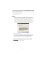
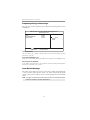
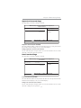
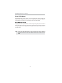
Motherboard User’s Guide This publication, including photographs, illustrations and software, is under the protection of international copyright laws, with all rights reserved. Neither this guide, nor any of the material contained herein, may be reproduced without the express written consent of the manufacturer. The information in this document is subject to change without notice. The manufacturer makes no representations or warranties with respect to the contents hereof and specifically disclaims any implied warranties of merchantability or fitness for any particular purpose. Further, the manufacturer reserves the right to revise this publication and to make changes from time to time in the content hereof without obligation of the manufacturer to notify any person of such revision or changes. Trademarks Microsoft, MS-DOS and Windows are registered trademarks of Microsoft Corp. AMD, Athlon, Sempron and Duron are registered trademarks of AMD Corp. Other names used in this publication may be trademarks and are acknowledged. Static Electricity Precautions 1. Don’t take this motherboard and components out of their original staticproof package until you are ready to install them. 2. While installing, please wear a grounded wrist strap if possible. If you don’t have a wrist strap, discharge static electricity by touching the bare metal of the system chassis. 3. Carefully hold this motherboard by its edges. Do not touch those components unless it is absolutely necessary. Put this motherboard on the top of static-protection package with component side facing up while installing. Pre-Installation Inspection 1. Inspect this motherboard whether there are any damages to components and connectors on the board. 2. If you suspect this motherboard has been damaged, do not connect power to the system. Contact your motherboard vendor about those damages. Copyright © 2010 All Rights Reserved A51G Series, V1.0 October, 2010 i Motherboard User’s Guide Table of Contents Trademark ............................................................................................................ i Chapter 1: Introduction ..................................................................................... 1 Key Features .................................................................................................................... 1 Package Contents ........................................................................................................... 4 Chapter 2: Motherboard Installation .............................................................. 5 I/O Ports .......................................................................................................................... 5 Motherboard Components.................................................................................. 6 Installing the Processor ................................................................................................. 7 Installing Memory Modules .......................................................................................... 8 Jumper Settings ............................................................................................................ 1 0 Install the Motherboard ............................................................................................... 11 Connecting Optional Devices ..................................................................................... 1 2 Install Other Devices .................................................................................................... 1 4 Expansion Slots ............................................................................................................ 1 5 Chapter 3: BIOS Setup Utility ....................................................................... 17 Introduction .................................................................................................................. 1 7 Running the Setup Utility...................................................................................17 Standard CMOS Setup Page ....................................................................................... 1 8 Advanced Setup Page .................................................................................................. 2 0 Advanced Chipset Setup Page .................................................................................... 2 2 Integrated Peripherals Page ....................................................................................... 2 3 Power Management Setup Page ................................................................................ 2 5 PCI/PnP Setup Page .................................................................................................... 2 6 PC Health Status Page ................................................................................................ 2 6 Frequency/Voltage Control Page ............................................................................... 3 0 Load Default Settings ................................................................................................... 3 0 Supervisor Password Page .......................................................................................... 3 1 User Password Page .................................................................................................... 3 1 Save & Exit Setup ......................................................................................................... 3 2 Exit Without Saving ...................................................................................................... 3 2 Chapter 4: Software & Applications .............................................................. 33 Introduction .................................................................................................................. 3 3 Installing Support Software ........................................................................................ 3 3 Bundled Software Installation .................................................................................... 3 5 Chapter 5: Setting Up AMD SB700 RAID Configuration ........................... 36 Setting Up a bootable RAID Array ............................................................................ 3 6 ii Motherboard User’s Guide Chapter 6: Trouble Shooting Tips ................................................................. 43 Start up problems during assemly .............................................................................. 4 3 Start up problems after prolong use .......................................................................... 4 4 Maintenance and care tips .......................................................................................... 4 4 Notice: 1. Owing to Microsoft’s certifying schedule is various to every supplier, we might have some drivers not certified yet by Microsoft. Therefore, it might happen under Windows XP that a dialogue box (shown as below) pops out warning you this software has not passed Windows Logo testing to verify its compatibility with Windows XP. Please rest assured that our RD department has already tested and verified these drivers. Just click the “Continue Anyway” button and go ahead the installation. 2. USB 2.0 Driver Limitations: 2-1. The USB 2.0 driver only supports Windows XP and Windows 2000. 2-2. If you connect a USB 2.0 hub to the root hub, plugging USB devices into this hub, the system might not successfully execute certain USB devices’ connection because it could not recognize these devices. Currently, we are working on such limitations’ solution. As soon as the olution is done, the updated USB drive will be released to our website: www.pcchips.com for your downloading. iii Motherboard User’s Guide Chapter 1 Introduction This motherboard is a high performance, enhanced function motherboard that supports socket for AMD PhenomTM II (socket AM3) processor for high-end business or personal desktop markets. This motherboard is based on NVIDIA® MCP61 Premium media and communications processor (MCP) for best desktop platform solution. MCP61P is a single-chip, highly integrated, high performance HyperTransport peripheral controller, unmatched by any other single chip-device controller. The memory controller supports DDR3 memory DIMM frequencies of 1333/1066/800. It supports two DDR3 sockets with maximum memory size of 8 GB*. High resolution graphics via one PCI Express x16 slot, one PCI Express x1 slot, 10 USB 2.0 ports (4 USB ports and 3 USB 2.0 headers support additional 6 USB ports) and SATA support with RAID function. There is an advanced full set of I/O ports in the rear panel, including PS/2 mouse and keyboard connectors, COM, VGA, four USB ports, one optional LPT port, one LAN port and audio jacks for microphone, line-in and line-out. This motherboard is designed in a Micro ATX form factor using a four-layer printed circuit board and measures 244 mm x 214 mm. * Due to the DRAM maximum size is 2 GB at present, the memory maximum size we have tested is 4 GB. Key Features The key features of this motherboard include: Socket-AM3 Processor Support • Accommodates AMD PhenomTM II (socket AM3) processor • Supports up to 2000 MT/s HyperTransportTM (HT) interface Speeds • High-performance HyperTransport CPU interface HyperTransportTM Technology is a point-to-point link between two devices,it enables integrated circuits to exchange information at much higher speeds than currently available interconnect technologies. This board supports CPU up to 95W TDP only. 1 Motherboard User’s Guide Chipset The NVIDIA® MCP61P is a single-chip with proven reliability and performance. • 1 GHz Hyper Transport x16 up and down links to the AMD socket AM2+/AM2 CPUs • PCI Express 16 lane link interface for external graphics processors • PCI v2.3 interface at 33 MHz • Integrated SATA 3.0 Gb/s Host Controller • Ten USB 2.0 ports supported • Fast ATA-133 IDE controller Memory • DDR3 1333/1066/800 DDR3 SDRAM with Dual-channel supported • Accommodates two unbuffered DIMMs • 2 x 240-pin DDR3 DIMM sockets support up to 8 GB Audio The onboard Audio provides the following features: • 5.1 Channel High Definition Audio Codec • Exceeds Microsoft Windows Logo Program (WLP) Requirements • ADCs supports 44.1/48k/96k/192k sample rate • Power Support: Digital: 3.3V;Analog: 5.0V Onboard LAN (optional) The onboard LAN provides the following features: • 10/100 full/half duplex operation • Support MII and 7-wire SNI (Serial Network Interface) • IEEE 802.3/802.3u compliant Expansion Options The motherboard comes with the following expansion options: • One PCI Express x 16 slot for Graphics Interface • One PCI Express x 1 slot • Two 32-bit PCI v2.3 compliant slots • One IDE connector supporting up to two IDE devices • One floppy disk drive interface • Four 7-pin SATA connectors 2 Chapter 1: Introduction This motherboard supports Ultra DMA bus mastering with transfer rates of 133/100/66/33 Mb/s. Integrated I/O The motherboard has a full set of I/O ports and connectors: • Two PS/2 ports for mouse and keyboard • One Serial port • One optional parallel port • One VGA port • Four USB ports • One LAN port • Audio jacks for microphone, line-in and line-out BIOS Firmware The motherboard uses AMI BIOS that enables users to configure many system features including the following: • Power management • Wake-up alarms • CPU parameters • CPU and memory timing The firmware can also be used to set parameters for different processor clock speeds. 3 Motherboard User’s Guide Note: Hardware specifications and software items are subject to change without notification. Package Contents Your motherboard package ships with the following items: The motherboard The User’s Guide Two Serial ATA cables The Software support disk Optional Accessories You can purchase the following optional accessories for this motherboard. The Serial ATA cable The Serial ATA power cable Note: You can purchase your own optional accessories from the third party, but please contact your local vendor on any issues of the specification and compatibility. 4 Chapter 2: Motherboard Installation Chapter 2 Motherboard Installation To install this motherboard in a system, please follow these instructions in this chapter: Identify the motherboard components Install a CPU Install one or more system memory modules Make sure all jumpers and switches are set correctly Install this motherboard in a system chassis (case) Connect any extension brackets or cables to headers/connectors on the motherboard Install peripheral devices and make the appropriate connections to headers/connectors on the motherboard Note: 1 2 Before installing this motherboard, make sure jumper CLR_CMOS is under Normal setting. See this chapter for information about locating CLR_CMOS and the setting options. Never connect power to the system during installation; otherwise, it may damage the motherboard. I/O Ports The illustration below shows a side view of the built-in I/O ports on the motherboard. 5 Motherboard User’s Guide Motherboard Components LABEL 1. CPU Socket CO MPO NENTS Socket for AMD Phenom TM II (socket AM3) processor 2. CPU_FAN CPU cooling fan connector 3. DDR3_1~2 240-pin DDR3 SDRAM slots 4. CASE Chassis detect header 5. FDD Floppy disk drive connector 6. PWR Standard 24-Pin AT X power connector 7. IDE Primary IDE connector 8. SATA1~4 Serial AT A connectors 9. PANEL Front panel Switch/LED header 10. F_USB1~3 Front panel USB headers 11. USBPWR_F Front panel USB power select jumper 12. SPK Speaker header 13. CLR_CMOS Clear CMOS jumper 14. SYS_FAN 15. CD_IN System cooling fan connector Analog audio input header 16. F_AUDIO Front panel audio header 17. SPDIFO SPDIF out header 18. PCI1~2 32-bit add-on card slots 19. PCIEX1 PCI Express x1 slot 20. PCIEX16 PCI Express x16 graphics card slot 21. AT X12V 4-pin +12V power connector 22. USBPWR_R Rear USB/PS2 power select jumper 6 Chapter 2: Motherboard Installation PS/2 Mouse Use the upper PS/2 port to connect a PS/2 pointing device. PS/2 Keyboard Use the lower PS/2 port to connect a PS/2 keyboard. VGA Port Connect your monitor to the VGA port. Serial Port(COM) Use the COM port to connect serial devices such as mice or fax/modems. LAN Port Connect an RJ-45 jack to the LAN port to connect your computer to the Network. USB Ports Use the USB ports to connect USB devices. Parallel Port Connect your monitor to the Parallel port. (LPT )(optional) Audio Ports Use the three audio ports to connect audio devices. T he first jack is for stereo line-in signal. T he third jack is for microphone. Installing the Processor This motherboard has a socket AM3 processor socket. When choosing a processor, consider the performance requirements of the system. Performance is based on the processor design, the clock speed and system bus frequency of the processor, and the quantity of internal cache memory and external cache memory. 7 Motherboard User’s Guide CPU Installation Procedure Follow these instructions to install the CPU: 1 2 3 4 5 6 Unhook the locking lever of the CPU socket. Pull the locking lever away from the socket and raising it to the upright position. Match the pin1 corner marked as the beveled edge on the CPU with the pin1 corner on the socket. Insert the CPU into the socket. Do not use force. Push the locking lever down and hook it under the latch on the edge of socket. Apply thermal grease to the top of the CPU. Install the cooling fan/heatsink unit onto the CPU, and secure them all onto the socket base. Plug the CPU fan power cable into the CPU fan connector (CPU_FAN1) on the motherboard. Note: To achieve better airflow rates and heat dissipation, we suggest that you use a high quality fan with 4800 rpm at least. CPU fan and heatsink installation procedures may vary with the type of CPU fan/heatsink supplied. The form and size of fan/heatsink may also vary. Installing Memory Modules This motherboard accommodates two 240-pin DIMM sockets (Dual Inline Memory Module) for unbuffered DDR3 1333/1066 memory modules (Double Data Rate SDRAM), and maximum 8 GB installed memory. 8 Chapter 2: Motherboard Installation Over its predecessor, DDR3-SDRAM offers greater bandwidth and density in a smaller package along with a reduction in power consumption. In addition, DDR2SDRAM offers new features and functions that enable a higher clock rate and data rate operations of 800 MHz , 1066 MHz and 1333 MHz. DDR3 transfers 64 bits of data twice every clock cycle. Memory Module Installation Procedure These modules can be installed with up to 8 GB system memory. Refer to the following to install the memory module. 1. Push down the latches on both sides of the DIMM socket. 2. Align the memory module with the socket. There is a notch on the DIMM socket that you can install the DIMM module in the correct direction. Match the cutout on the DIMM module with the notch on the DIMM socket. 3. Install the DIMM module into the socket and press it firmly down until it is seated correctly. The socket latches are levered upwards and latch on to the edges of the DIMM. 4. Install any remaining DIMM modules. 9 Motherboard User’s Guide Note for dual-channel DDR2: 1. You CAN NOT use only one DIMM2 for it might cause the system shutdown. 2. You need to use DIMM1 and DIMM2 with the same size of memory modules. Jumper Settings Connecting two pins with a jumper cap is SHORT; removing a jumper cap from these pins, OPEN. CLR_CMOS: Clear CMOS Jumper Use this jumper to clear the contents of the CMOS memory. You may need to clear the CMOS memory if the settings in the Setup Utility are incorrect and prevent your motherboard from operating. To clear the CMOS memory, disconnect all the power cables from the motherboard and then move the jumper cap into the CLEAR setting for a few seconds. Function Jumper NORMAL CMOS Short Pins 1-2 CLEAR Short Pins 2-3 Note: To avoid the system unstability after clearing CMOS, we recommend users to enter the main BIOS setting page to “Load Optimal De-faults” and then “Save Changes and Exit”. 10 Chapter 2: Motherboard Installation Install The Motherboard Install the motherboard in a system chassis (case). The board is a Micro ATX size motherboard. You can install this motherboard in an ATX case. Make sure your case has an I/O cover plate matching the ports on this motherboard. Install the motherboard in a case. Follow the case manufacturer’s instructions to use the hardware and internal mounting points on the chassis. Connect the CPU cooling fan cable to CPU_FAN. Connect the standard power supply connector to PWR. Connect the case speaker cable to SPK. Connect the cable from the cooling fan to the SYS_FAN fan power connector on the motherboard. Connect the auxiliary case power supply connector to ATX_12V. Connect the case switches and indicator LEDs to the PANEL. Pin 1 3 5 7 9 Signal HD_LED_P(+) HD_LED_N(-) RESET_SW_N(-) RESET_SW_P(+) RSVD_DNU Pin 2 4 6 8 10 11 Signal FP PWR/SLP(+) FP PWR/SLP(-) POWER_SW_P(+) POWER_SW_N(-) KEY Motherboard User’s Guide Connecting Optional Devices Refer to the following for information on connecting the motherboard’s optional devices: SPK: Speaker Header Connect the cable from the PC speaker to the SPK header on the motherboard. Pin 1 2 3 4 Signal VCC Key GND Signal F_AUDIO: Front Panel Audio Header This header allows the user to install auxiliary front-oriented microphone and lineout ports for easier access. Pin 1 3 5 7 9 Signal PORT1L PORT1R PORT2R SENSE_SEND PORT2L Pin 2 4 6 8 10 12 Signal AUD_GND PRESENCE# SENSE1_RETURN KEY SENSE2_RETURN Chapter 2: Motherboard Installation F_USB1~3: Front Panel USB Headers The motherboard has USB ports installed on the rear edge I/O port array. Additionally, some computer cases have USB ports at the front of the case. If you have this kind of case, use auxiliary USB headers F_USB1~2 to connect the front-mounted ports to the motherboard. Here is a list of USB pin assignments. Pin 1 3 5 7 9 Signal VERG_FP_USBPWR0 USB_FP_P0(-) USB_FP_P0(+) GROUND KEY Pin 2 4 6 8 10 Signal VERG_FP_USBPWR0 USB_FP_P1(-) USB_FP_P1(+) GROUND GROUND 1. Locate the F_USB1~3 headers on the motherboard. 2. Plug the bracket cable onto the F_USB1~3 headers. 3. Remove a slot cover from one of the expansion slots on the system chassis. Install an extension bracket in the opening. Secure the extension bracket to the chassis with a screw. SPDIFO: SPDIF out header This is an optional header that provides an S/PDIF (Sony/Philips Digital Interface) output to digital multimedia device through optical fiber or coaxial connector. Pin 1 2 3 4 Signal SPDIF +5VA Key GND CASE: Chassis intrusion detect header This detects if the chassis cover has been removed. This function needs a chassis equipped with instrusion detection switch and needs to be enabled in BIOS. Pin 1-2 Function Short Open Chassis cover is removed Chassis cover is closed CD_IN: Analog Audio Input connector Pin 1 2 3 4 Signal Name Function CD_L CD In left channel GND Ground GND Ground CD_R CD In right channel 13 Motherboard User’s Guide Install Other Devices Install and connect any other devices in the system following the steps below. IDE Devices IDE devices include hard disk drives, high-density diskette drives, and CD-ROM or DVD-ROM drives, among others. The mainboard ships with an IDE cable that can support one or two IDE devices. If you connect two devices to a single cable, you must configure one of the drives as Master and one of the drives as Slave. The documentation of the IDE device will tell you how to configure the device as a Master or Slave device. The Master device connects to the end of the cable. Install the device(s) and connect power from the system power supply. Use the cable provided to connect the device(s) to the Primary IDE channel connector IDE1 on the motherboard. If you want to install more IDE devices, you can purchase a second IDE cable and connect one or two devices to the Secondary IDE channel connector IDE2 on the motherboard. If you have two devices on the cable, one must be Master and one must be Slave. 14 Chapter 2: Motherboard Installation Serial ATA Devices The Serial ATA (Advanced Technology Attachment) is the standard interface for the IDE hard drives, which is designed to overcome the design limitations while enabling the storage interface to scale with the growing media rate demands of PC platforms. It provides you a faster transfer rate of 1.5 Gb/s. If you have installed a Serial ATA hard drive, you can connect the Serial ATA cables to the Serial ATA hard drive or the connector on the motherboard. On the motherboard, locate the Serial ATA connectors SATA1-2, which support new Serial ATA devices for the highest data transfer rates, simpler disk drive cabling and easier PC assembly. It eliminates limitations of the current Parallel ATA interface, but maintains register compatibility and software compatibility with Parallel ATA. Expansion Slots This motherboard has one PCI Express x16, one PCI Express x1 and two 32-bit PCI slots. 15 Motherboard User’s Guide Follow the steps below to install an PCI Express x16/ PCI Express x1/CNR/PCI expansion card. 1. Locate the PCI Express x16, PCI Express x1, CNR or PCI slots on the mainboard. 2. Remove the blanking plate of the slot from the system chassis. 3. Install the edge connector of the expansion card into the slot. Ensure the edge connector is correctly seated in the slot. 4. Secure the metal bracket of the card to the system chassis with a screw. PCI Express x16 Slot You can install an external PCI Express graphics card that is fully compliant to the PCI Express Base Specification revsion 1.0a. PCI Express x1 Slot The two PCI Express x1 slots are fully compliant to the PCI Express Base Specification revision 1.0a as well. PCI Slots You can install the 32-bit PCI interface expansion cards in the slots. 16 Chapter 3: BIOS Setup Utility Chapter 3 BIOS Setup Utility Introduction The BIOS Setup Utility records settings and information of your computer, such as date and time, the type of hardware installed, and various configuration settings. Your computer applies the information to initialize all the components when booting up and basic functions of coordination between system components. If the Setup Utility configuration is incorrect, it may cause the system to malfunction. It can even stop your computer booting properly. If it happens, you can use the clear CMOS jumper to clear the CMOS memory which has stored the configuration information; or you can hold down the Page Up key while rebooting your computer. Holding down the Page Up key also clears the setup information. You can run the setup utility and manually change the configuration. You might need to do this to configure some hardware installed in or connected to the motherboard, such as the CPU, system memory, disk drives, etc. Running the Setup Utility Every time you start your computer, a message appears on the screen before the operating system loading that prompts you to “Hit <DEL>if you want to run SETUP” . Whenever you see this message, press the Delete key, and the Main menu page of the Setup Utility appears on your monitor. CMOS Setup Utility – Copyright (C) 1985-2005, American Megatrends, Inc Standard CMOS Setup Advanced Setup Advanced Chipset Setup Integrated Peripherals Power Management Setup PCI/PnP Configuration PC Health Status Frequency/Voltage Control Load Default Settings Supervisor Password User Password Save & Exit Setup Exit Without Saving : Move Enter: Select +/-/: Value F10: Save Esc: Exit F1: General Help F9: Optimized Defaults V02.67 (C) Copyright 1985-2009, American Megatrends, Inc. You can use cursor arrow keys to highlight anyone of options on the main menu page. Press Enter to select the highlighted option. Press the Escape key to leave the setup utility. Press +/-/ to modify the selected field’s values. 17 Motherboard User’s Guide Some options on the main menu page lead to tables of items with installed values that you can use cursor arrow keys to highlight one item, and press PgUp and PgDn keys to cycle through alternative values of that item. The other options on the main menu page lead to dialog boxes requiring your answer OK or Cancel by selecting the [OK] or [Cancel] key. If you have already changed the setup utility, press F10 to save those changes and exit the utility. Press F1 to display a screen describing all key functions. Press F9 to load optimtimal settings. Standard CMOS Setup Page This page displays a table of items defining basic information of your system. CMOS Setup Utility – Copyright (C) 1985-2005, American Megatrends, Inc. Standard CMOS Setup Date Time Help Item Tue 07/28/2009 00: 12: 01 Primary IDE Master Primary IDE Slave SATA1 SATA2 SATA3 SATA4 User [Enter], [TAB] or [SHIFT-TAB] to select a field. Not Detected Not Detected Not Detected Not Detected Not Detected Not Detected IDE BusMaster Enabled Drive A: 1.44 MB 3 1/2” Use [+] or [-] to configure system Date. : Move Enter: Select +/-/: Value F10: Save Esc: Exit F1: General Help F9: Optimized Defaults Date & Time These items set up system date and time. 18 Chapter 3: BIOS Setup Utility Primary IDE Master/Slave, SATA 1~4 Your computer has one IDE channel which can be installed with one or two devices (Master and slave.) In addition, this motherboard supports four SATA channels and each SATA allows one device to be installed. Use these items to configure each device on the IDE channel. CMOS Setup Utility – Copyright (C) 1985-2005, American Megatrends, Inc. Primary IDE Master Primary IDE Master Device : Help Item Not Detected Type LBA/Large Mode Block (Muti-Sector Transfer) PIO Mode DMA Mode S.M.A.R.T 32Bit Data Transfer Auto Auto Auto Auto Auto Auto Enabled Select the type of device connected to the system : Move Enter: Select +/-/: Value F10: Save Esc: Exit F1: General Help F9: Optimized Defaults Type (Auto) Use this item to configure the type of the IDE device that you specify. If the feature is enabled, it will enhance hard disk performance by reading or writing more data during each transfer. LBA/Large Mode (Auto) Use this item to set the LAB/Large mode to enhance hard disk performance by optimizing the area the hard disk is visited each time. Block (Multi-Sector Transfer) (Auto) If the feature is enabled, it will enhance hard disk performance by reading or writing more data during each transfer. PIO Mode (Auto) Use this item to set the PIO mode to enhance hard disk performance by optimizing the hard disk timing. DMA Mode (Auto) DMA capability allows user to improve the transfer-speed and data-integrity for compatible IDE devices. S.M.A.R.T. (Auto) The S.M.A.R.T. (Self-Monitoring, Analysis and Reporting Technology) system is a diagnostics technology that monitors and predicts device performance. S.M.A.R.T. software resides on both the disk drive and the host computer. 32Bit Data Transfer (Enabled) Use this item to enable or disable the 32Bit Data Transfer. 19 Motherboard User’s Guide IDE Bus Master(Enabled) This item enables or disables the DMA under DOS mode. We recommend you to leave this item at the default value. Drive A (1.44 MB 3 1/2” ) This item defines the characteristics of any dikette drive attached to the system. You can connect one diskette drive. Advanced Setup Page This page sets up more advanced information about your system. Handle this page with caution. Any changes can affect the operation of your computer. CMOS Setup Utility – Copyright (C) 1985-2005, American Megatrends, Inc. Advanced Setup HT Frequency AMD C&Q Quick Power on Self Test Boot Up Numlock Status APIC Mode 1st Boot Device 2nd Boot Device 3rd Boot Device Hard Disk Drives Removable Drives Boot Other Device Auto Enabled Enabled On Enabled USB Flash Disk CD/DVD 1st FLOPPY DRIVE Press Enter Press Enter Yes Help Item Auto 200 MHz 400 MHz 800 MHz 1000 MHz : Move Enter: Select +/-/: Value F10: Save Esc: Exit F1: General Help F9: Optimized Defaults HT Frequency (Auto) This item enables users to manually set up the HyperTransport frequency. If Manual, the HT Frequency Value will display, and the options are 200 MHz, 400 MHz, 600 MHz, 800 MHz and 1000 MHz. AMD C & Q (Enabled) This item helps the system to lower the frequency when CPU idles. When the frequency decreases, the temperature will drop automatically as well. Quick Power on Self Test (Enabled) Enable this item to shorten the power on testing (POST) and have your system start up faster. You might like to enable this item after you are confident that your system hardware is operating smoothly. Boot Up Numlock Status (On) This item defines if the keyboard Num Lock key is active when your system is started. 20 Chapter 3: BIOS Setup Utility APIC Mode (Enabled) This item allows you to enable or disable the APCI (Advanced Programmable Interrupt Controller) mode. APIC provides symmetric multi-processing (SMP) for systems, allowing support for up to 60 processors. 1st/2nd/3rd Boot Device (USB Flash Disk/CD/DVD/1st FLOPPY DRIVE) Use these items to determine the device order the computer uses to look for an operating system to load at start-up time. The devices showed here will be different depending on the exact devices installed on your motherboard. Hard Disk Drives (Press Enter) Scroll to this item and press < Enter > to view the following screen: CMOS Setup Utility – Copyright (C) 1985-2005, American Megatrends, Inc. Hard Disk Drives Hard Disk Drives 1st Drive 2nd Drive Help Item ST31500341AS USB Flash Disk Specifies the boot sequence from the available devices. : Move Enter: Select +/-/: Value F10: Save Esc: Exit F1: General Help F9: Optimized Defaults Removable Drives (Press Enter) Scroll to this item and press < Enter > to view the following screen: CMOS Setup Utility – Copyright (C) 1985-2005, American Megatrends, Inc. Removable Drives Removable Drives 1st Drive Help Item 1st FLOPPY DRIVE Specifies the boot sequence from the available devices. : Move Enter: Select +/-/: Value F10: Save Esc: Exit F1: General Help F9: Optimized Defaults 21 Motherboard User’s Guide Boot other Device (Yes) When enabled, the system searches all other possible locations for an operating system if it fails to find one in the devices specified under the First, Second, and Third boot devices. Advanced Chipset Setup Page This page sets up more advanced information about your system. Handle this page with caution. Any changes can affect the operation of your computer. CMOS Setup Utility – Copyright (C) 1985-2005, American Megatrends, Inc. Adcanced Chipset Setup Help Item Dram Frequency Auto Dram Timing Auto DCT Unganged Mode Always Share Memory Auto Detection Auto Share Memory Size 64MB Options Auto Limit Manual : Move Enter: Select +/-/: Value F10: Save Esc: Exit F1: General Help F9: Optimized Defaults Dram Frequency (Auto) This item enables users to adjust the DRAM frequency. The default setting is auto and we recommend users leave the setting unchanged. Modify it at will may cause the system to be unstable. Dram Timing (Auto) This item allows you to enable or disable the DRAM timing defined by the Serial Presence Detect electrical. Users please note that if setting this item to auto, the following two items are not available. DCT Unganged Mode (Always) This item is used to select the DCT mode (DRAM Controller mode). Share Memory Auto Detection (Auto) Disable this item to set the Share Memory Size. And if the item is set to Auto, Share Memory Size can be controlled according to the dram size: When the dram size is less than 512 MB, Share Memory Size should be set to 32 MB; When the dram size is over 512MB, and it is dual channel, Share Memory Size should be set to 64 MB; 22 Chapter 3: BIOS Setup Utility When the dram is single channel, its size is over 512MB: if the memory frequency is 667MHz, Share Memory Size should be set to 64 MB; if the memory frequency is 533MHz or 400MHz, Share Memory Size should be set to 32 MB. Share Memory Size (64 MB) This item displays the VGA Share Memory value size. Integrated Peripherals Page This page sets up some parameters for peripheral devices connected to the system. CMOS Setup Utility – Copyright (C) 1985-2005, American Megatrends, Inc. Integrated Peripherals Onboard IDE Controller Serial-ATA 0 SATA Configuration nVidia RAID Setup Onboard AUDIO Function Onboard LAN Function Onboard LAN Boot ROM Serial Port 1 Address Onboard IR USB Function Legacy USB Support Enabled Enabled SATA Mode Help Item DISABLED:disables the integrated IDE Controller. PRIMARY:enables only the Primary IDE Controller. SECONDARY:enables only the Secondary IDE Controller. BOTH:enables both IDE Controller. Press Enters Enabled Enabled Disabled 3F8/IRQ4 Disabled Enabled Enabled : Move Enter: Select +/-/: Value F10: Save Esc: Exit F1: General Help F9: Optimized Defaults Onboard IDE Controller (Enabled) Use this item to enable or disable the onboard IDE interface. Serial-ATA 0 (Enabled) This item allows you to enable or disable the onboard SATA controller. SATA Configuration (SATA Mode) Use this item to show the mode of the Serial ATA Configuration options. 23 Motherboard User’s Guide nVidia RAID Setup (Press Enter) Scroll to this item and press < Enter > to view the following screen: CMOS Setup Utility – Copyright (C) 1985-2005, American Megatrends, Inc. nVidia RAID Setup RAID Setup Help Item : Move Enter: Select +/-/: Value F10: Save Esc: Exit F1: General Help F9: Optimized Defaults Onboard AUDIO Function (Enabled) Use this item to enable or disable the onboard Audio function. Onboard LAN Function (Enabled) Use this item to enable or disable the onboard LAN function. Onboard LAN Boot ROM (Disabled) Use this item to enable or disable the booting from the onboard LAN or a network addin card with a remote boot ROM installed. Serial Port1 Address (3F8/IRQ4) Use this item to enable or disable the onboard COM1 serial port, and to assign a port address. OnBoard IR (Disabled) Use this item to enable or disable the onboard infrared port, and to assign a port address. USB Functions (Enabled) Use this item to enable or disable the USB function. Legacy USB Support (Enabled) Use this item to enable or disable support for legacy USB devices. Setting to Auto allows the system to detect the presence of USB device at startup. If detected, the USB controller legacy mode is enabled. If no USB device is detected, the legacy USB support is disabled. 24 Chapter 3: BIOS Setup Utility Power Management Setup Page This page sets some parameters for system power management operation. CMOS Setup Utility – Copyright (C) 1985-2005, American Megatrends, Inc. Power Management Setup ACPI Suspend Type Resume By RING Resume By PCI/PCI-E/Lan PME Resume By USB (S3) Resume By PS2 KB (S3) Resume By PS2 MS (S3) Resume on RTC Alarm S3 (STR) DIsabled Disabled Disabled Disabled Disabled Disabled Help Item Select the ACPI state used for System Suspend. : Move Enter: Select +/-/: Value F10: Save Esc: Exit F1: General Help F9: Optimized Defaults ACPI Suspend Type (S3 (STR)) Use this item to define how your system suspends. In the default, S3, the suspend mode is a suspend to RAM, i.e, the system shuts down with the exception of a refresh current to the system memory. Resume By RING (Disabled) An input signal on the serial Ring Indicator (RI) line (in other words, an incoming call on the modem) awakens the system from a soft off state. Resume By PCI/PCI-E/Lan PME (Disabled) These items specify whether the system will be awakened from power saving modes when activity or input signal of the specified hardware peripheral or component is detected. Resume By USB (S3) (Disabled) This item allows you to enable/disable the USB device wakeup function from S3 mode. Resume By PS2 KB (S3) (Disabled) This item enables or disables you to allow keyboard activity to awaken the system from power saving mode. Resume By PS2 MS (S3) (Disabled) This item enables or disables you to allow mouse activity to awaken the system from power saving mode. Resume on RTC Alarm The system can be turned off with a software command. If you enable this item, the system can automatically resume at a fixed time based on the system’s RTC (realtime clock). Use the items below this one to set the date and time of the wake-up alarm. You must use an ATX power supply in order to use this feature. 25 Motherboard User’s Guide PCI / PnP Setup Page This page sets up some parameters for devices installed on the PCI bus and those utilizing the system plug and play capability. CMOS Setup Utility – Copyright (C) 1985-2005, American Megatrends, Inc. PCI / PnP Setup Init Display First Help Item PCI Optionas Onboard PCI PCIExpress : Move Enter: Select +/-/: Value F10: Save Esc: Exit F1: General Help F9: Optimized Defaults Init Display First Use this item to select which graphics controller to use as the primary boot devices. PC Health Status Page On motherboards support hardware monitoring, this item lets you monitor the parameters for critical voltages, temperatures and fan speeds. CMOS Setup Utility – Copyright (C) 1985-2005, American Megatrends, Inc. PC Health Status -=- System Hardware Monitor-=Smart Fan Function Shutdown Temperature CPU Tcontrol System Temperature CPU Fan Speed CPU Vcore VDIMM VCC3 3VSB Case Open Warning Chassis Opened Help Item Press Enter Disabled : 42°C/107°F : 35°C/95°F : 1805 RPM : 1.128V : 1.488V : 3.440V : 3.376V Disabled No Disabled Enabled Clear : Move Enter: Select +/-/: Value F10: Save Esc: Exit F1: General Help F9: Optimized Defaults 26 Chapter 3: BIOS Setup Utility Smart Fan Function This page sets up some parameters for devices installed on the PCI bus and those utilizing the system plug and play capability. CMOS Setup Utility – Copyright (C) 1985-2005, American Megatrends, Inc. Smart Fan Function FAN1 Mode Setting SMART Fan Mode High Limit Temperature. (°C) High Limit Temperature. (°C) High Limit PWM Low Limit PWM Enabled Normal 60 37 200 56 Help Item Normal: auto adjusts depending on the CPU temperature. Quiet: auto minimizes fan speed for quiet environment operation. Silent: auto restricts fan speed to make system more quietly. Manual: The fan adjust depending on user’s parameter. : Move Enter: Select +/-/: Value F10: Save Esc: Exit F1: General Help F9: Optimized Defaults SMART Fan Mode (Normal) This item allows you to select the fan mode (Normal, Quiet, Silent, or Manual) for a better operation environment. If you choose Normal mode, the fan speed will be auto adjusted depending on the CPU temperature. If you choose Quite mode, the fan speed will be auto minimized for quiet environment. If you choose Silent mode, the fan speed will be auto restricted to make system more quietly. If you choose Manual mode, the fan speed will be adjust depending on users’ parameters. CMOS Setup Utility - Copyright (C) 1985-2005, American Megatrends, Inc. Smart Fan Function Help Item CPU SMART FAN Control SMART Fan Mode High Limit Temperature.(°C) Low Limit Temperature.(°C) High Limit PWM Low Limit PWM Enabled Quiet 65 52 200 40 Normal: auto adjusts depending on the CPU temperature. Quiet: auto minimizes fan speed for quiet environment operation. Silent: auto restricts fan speed to make system more quietly. Manual: the fan adjust depending on user’s parameter. mnlk : Move Enter : Select F1:General Help +/-/: Value F10: Save F9: Optimized Defaults 27 ESC: Exit Motherboard User’s Guide CMOS Setup Utility - Copyright (C) 1985-2005, American Megatrends, Inc. Smart Fan Function Help Item CPU SMART FAN Control SMART Fan Mode High Limit Temperature.(°C) Low Limit Temperature.(°C) High Limit PWM Low Limit PWM Enabled Silent 68 60 200 15 Normal: auto adjusts depending on the CPU temperature. Quiet: auto minimizes fan speed for quiet environment operation. Silent: auto restricts fan speed to make system more quietly. Manual: the fan adjust depending on user’s parameter. : Move Enter : Select +/-/: Value F10: Save ESC: Exit F1:General Help F9: Load Default Settings CMOS Setup Utility - Copyright (C) 1985-2005, American Megatrends, Inc. Smart Fan Function Help Item CPU SMART FAN Control SMART Fan Mode High Limit Temperature.(°C) Low Limit Temperature.(°C) High Limit PWM Low Limit PWM Enabled Manual 68 60 200 15 Normal: auto adjusts depending on the CPU temperature. Quiet: auto minimizes fan speed for quiet environment operation. Silent: auto restricts fan speed to make system more quietly. Manual: the fan adjust depending on user’s parameter. : Move Enter : Select F1:General Help +/-/: Value F10: Save ESC: Exit F9: Optimized Defaults 28 Chapter 3: BIOS Setup Utility System Component Characteristics These items display the monitoring of the overall inboard hardware health events, such as System temperature & CPU Tcontrol, CPU & DIMM voltage, CPU & system fan speed,...etc. • • • • • • • CPU Tcontrol System Temperature CPU FAN Speed CPU Vcore VDIMM VCC3 3VSB Case Open Warning (Disabled) This item enables or disables the warning if the case is opened up, and the item below indicates the current status of the case. Chassis Opened (No) This item indicates whether the case has been opened. 29 Motherboard User’s Guide Frequency/Voltage Control Page This page sets up some parameters for the hardware monitoring function of this motherboard. CMOS Setup Utility – Copyright (C) 1985-2005, American Megatrends, Inc. Frequency/Voltage Control Unlock Auto Detect DIMM/PCI Clk Spread Spectrum Disabled Enabled Enabled Help Item Options Disabled Enabled : Move Enter: Select +/-/: Value F10: Save Esc: Exit F1: General Help F9: Optimized Defaults Unlock (Disabled) This item allows you to enable or disable multi core CPU unlock function. It works depends on your CPU. Auto Detect DIMM/PCI Clk When this item is enabled, BIOS will disable the clock signal of free DIMM/PCI slots. Spread Spectrum (Enabled) If you enable spread spectrum, it can significantly reduce the EMI (Electro-Magnetic Interference) generated by the system. Load Default Settings This option opens a dialog box to ask if you are sure to install optimized defaults or not. You select [OK], and then <Enter>, the Setup Utility loads all default values; or select [Cancel], and then <Enter>, the Setup Utility does not load default values. Note: It is highly recommend that users enter this option to load optimal default values for accessing the best performance. 30 Chapter 3: BIOS Setup Utility Supervisor Password Page This page helps you install or change a password. CMOS Setup Utility – Copyright (C) 1985-2005, American Megatrends, Inc. Supervisor Password Supervisor Password Help Item : Not Installed Change Supervisor Password Press Enter Install or Change the password. : Move Enter: Select +/-/: Value F10: Save Esc: Exit F1: General Help F9: Optimized Defaults Supervisor Password (Not Installed) This item indicates whether a supervisor password has been set. If the password has been installed, Installed displays. If not, Not Installed displays. Change Supervisor Password (Press Enter) You can select this option and press <Enter> to access the sub menu. You can use the sub menu to change the supervisor password. User Password Page This page helps you install or change a password. CMOS Setup Utility – Copyright (C) 1985-2005, American Megatrends, Inc. User Password Help Item User Password : Not Installed Change User Password Press Enter Install or Change the password. : Move Enter: Select +/-/: Value F10: Save Esc: Exit F1: General Help F9: Optimized Defaults User Password (Not Installed) This item indicates whether an user password has been set. If the password has been installed, Installed displays. If not, Not Installed displays. Change User Password (Press Enters) You can select this option and press <Enter> to access the sub menu. You can use the sub menu to change the user password. 31 Motherboard User’s Guide Save & Exit Setup Highlight this item and press <Enter> to save the changes that you have made in the Setup Utility configuration. When the Save Changes and Exit dialog box appears, select [OK] to save and exit, or [Cancel] to return to the main menu. Exit Without Saving Highlight this item and press <Enter> to discard any changes that you have made in the Setup Utility and exit the Setup Utility. When the Discard Changes and Exit dialog box appears, select [OK] to discard changes and exit, or [Cancel] to return to the main menu. Note: If you have made settings that you do not want to save, use the “Discard Changes and Exit” item and select [OK] to discard any changes you have made. 32 Chapter 4: Software & Applications Chapter 4 Software & Applications Introduction This chapter describes the contents of the support DVD-ROM/CD-ROM that comes with the motherboard package. The support DVD-ROM/CD-ROM contains all useful software, necessary drivers and utility programs to properly run our products. More program information is available in a README file, located in the same directory as the software. To run the support disk, simply insert the disk into your DVD-ROM/CD-ROM drive. An Auto Setup screen automatically pops out, and then you can go on the auto-installing or manual installation depending on your operating system. If your operating system is Windows XP/Vista/7, it will automatically install all the drivers and utilities for your motherboard. Installing Support Software 1 2 3 Insert the support DVD-ROM/CD-ROM disk in the DVD-ROM/CDROM drive. When you insert the DVD-ROM/CD-ROM disk in the system DVDROM/CD-ROM drive, the disk automatically displays an Auto Setup screen. The screen displays three buttons of Setup, Browse CD and Exit on the right side, and three others Drivers, Utilities and Information at the bottom. Please see the following illustration. The Setup button runs the software auto-installing program as explained in next 33 Motherboard User’s Guide section. The Browse CD button is a standard Windows command that you can check the contents of the disc with the Windows file browsing interface. The Exit button closes the Auto Setup window. To run the program again, reinsert the DVD-ROM/CD-ROM disk in the drive; or click the DVD-ROM/CD-ROM driver from the Windows Explorer, and click the Setup icon. The Utilities button brings up a software menu. It shows the bundled software that this mainboard supports. The Information brings you to the Install Path where you can find out path names of software driver. Auto-Installing under Windows XP/Vista/7 If you are under Windows XP/7, please click the Setup button to run the software auto-installing program while the Auto Setup screen pops out after inserting the support DVD-ROM/CD-ROM: 1 The installation program loads and displays the following screen. Click the Next button. 2 Select the items that you want to setup by clicking on it (the default options are recommended). Click the Next button to proceed. 34 Chapter 4: Software & Applications 3 The support software will automatically install. Once any of the installation procedures start, software is automatically installed in sequence. You need to follow the onscreen instructions, confirm commands and allow the computer to restart as few times as needed to complete installing whatever software you selected. When the process is finished, all the support software will be installed and start working. Windows Vista/7 will appear below UAC (User Account Control) message after the system restart. You must select “Allow” to install the next driver. Continue this process to complete the drivers installation. Bundled Software Installation All bundled software available on the DVD-ROM/CD-ROM is for users’ convenience. You can install bundled software as follows: 1 Click the Utilities button while the Auto Setup screen pops out after inserting the support DVD-ROM/CD-ROM. 2 A software menu appears. Click the software you want to install. 3 Follow onscreen instructions to install the software program step by step until finished. 35 Motherboard User’s Guide Chapter 5 Setting Up AMD SB700 RAID Configuration Setting Up a boota ble RAID Ar bootab Arrray This section explains how to configure a bootable AMD RAID array. Setting Up the BIOS 1 Start your computer, then press Delete to enter the BIOS setup. The BIOS CMOS Setup Utility screen appears. Figure 1.1 2 BIOS CMOS Setup Utility Main Screen Use the arrow keys to select Integrated Peripherals (see Figure 1.1), then press Enter. The Integrated Peripherals screen (or a screen similar to it) appears. Figure 1.2 Integrated Peripherals Screen 36 Chapter 5: Setting Up AMD SB700 RAID Configuration 3 From the Integrated Peripherals Window, globally set SATA Mode select to RAID Mode (see Figure 1.2) 4 Press F10 to save the configuration and exit. The PC reboots. 5 Enter the RAID BIOS Setup by pressing Ctrl-F when prompted, and proceed to set up the AMD RAID BIOS as described in the next section. Configuring the AMD RAID BIOS The AMD RAID BIOS set up lets you choose the RAID type and which hard drives you want to make part of the array. Entering the RAID BIOS Setup: 1 Wait until you see the RAID software prompting you to press F10. The RAID prompt appears as part of the system POST and boot process prior to loading of the OS. You have a few seconds to press F10 before the screen disappears (see Figure 1.3). Figure 1.3 2 Press F10 to enter Define a New Array page. 37 Motherboard User’s Guide The NVIDIA RAID Utility¡ efine a New Array screen appears (Figure 1.4) Figure 1.4 MediaShield BIOS By default, RAID Mode is set to Mirroring and Striping Block is set to Optimal. Using the Define a New Array Screen If necessary, press the tab key to move from field to field until the appropriate field is highlighted. • Selecting the RAID Mode By default, this is set to Mirroring. To change to a different RAID mode, press the down arrow key until the mode that you want appears in the RAID Mode box¡either Mirroring, Striping, Spanning, Stripe Mirroring or RAID 5. Note: Not all RAID levels are supported on all platforms. And enough Hard disks are required to complete the RAID configuration. • Selecting the Stripe Block Size Stripe block size is given in kilobytes, and affects how data is arranged on the disk. It is recommended to leave this value at the default Optimal, which is 64KB, but the values can be between 4 KB and 128 KB (4, 8, 16, 32, 64, and 128 KB) 38 Chapter 5: Setting Up AMD SB700 RAID Configuration Assigning the Disks Select the Assignment to Y to designate a free disk to be used as a RAID array disk. Figure 1.5 illustrates the Define a New Array screen after two disks have been assigned as RAID 0 array disks. Figure 1.5 MediaShield BIOS—NArray Disks Assigned Completing the RAID BIOS Setup 1 After assigning your RAID array disk, press F7. The Clear disk array prompt appears (Figure 1.6). Figure 1.6 Clear Disk Data Prompt 39 Motherboard User’s Guide 2 Press Y to clear the disk data. The Array List screen appears, where you can review the RAID arrays that you have set up. Figure 1.7 Array List Window 3 Use the arrow keys to select the array that you want to set up, then press B to specify the array as bootable. 4 Press Enter to view and verify details. The Array Detail screen shows various information about the array that you selected, such as Striping Block used, RAID Mode, Striping Width, Disk Model Name, and disk capacity. 5 If you want to mark this disk as empty and wipe out all its contents, press C. 6 At the prompt, press Y to wipe out all the data, otherwise press N. 7 Press Enter again to go back to the previous screen and then press F10 to exit the RAID setup. 40 Chapter 5: Setting Up AMD SB700 RAID Configuration Installing the RAID Drivers Your system may come with a Windows install CD that already includes NVIDIA RAID drivers. If so, then this section is not relevant. If that is not the case (or you are trying to install a new version of Windows), then you will need an NVIDIA RAID driver F6 install floppy. Check to see if one came with your system. If not, you can create one by downloading the appropriate driver package and following the steps in this section. 1 Copy all files in "…\IDE\WinXP\sataraid" to a floppy disk. (For Windows 2000, substitute "Win2K" in the path.) 2 After you complete the RAID BIOS setup, boot from the Windows CD. The Windows Setup program starts. 3 Press F6 and wait a few moments for the Windows Setup screen to appear. Figure 1.8 4 Windows Setup—Specify Devices Specify the NVIDIA drivers. a Insert the floppy that has the RAID driver, press S, then press Enter. The following Windows Setup screen appears: Figure 1.9 Windows Setup—Selected SCSI Adapter 41 Motherboard User’s Guide b Select “NVIDIA RAID CLASS DRIVER (required)” and then press Enter. c Press S again at the Specify Devices screen, then press Enter. d Select “NVIDIA NForce Storage Controller (required)” and then press Enter. The following Windows Setup screen appears listing both drivers:. Figure 1.10 5 Windows Setup—NVIDIA drives listed Press Enter to continue with Windows XP Installation. Be sure to leave the floppy disk inserted in the floppy drive until the blue screen portion of Windows XP installation is completed, then take out the floppy. 6 Follow the instructions on how to install Windows XP. After Windows XP is completely installed, it is recommended that you install the ForceWare software in order to access the MediaShield RAID Management tool. Note: Each time you add a new hard drive to a RAID array, the RAID driver will have to be installed under Windows once for that hard drive. After that, the driver will not have to be installed. 42 Chapter 6: Trouble Shooting Tips Chapter 6 Trouble Shooting Tips Star t up pr ob lems during assemb prob oblems assembll y After assembling the PC for the first time you may experience some start up problems. Before calling for technical support or returning for warranty, this chapter may help to address some of the common questions using some basic troubleshooting tips. a) System does not power up and the fans are not running. 1.Disassemble the PC to remove the VGA adaptor card, DDR memory, LAN, USB and other peripherals including keyboard and mouse. Leave only the motherboard, CPU with CPU cooler and power supply connected. Turn on again to see if the CPU and power supply fans are running. 2. Make sure to remove any unused screws or other metal objects such as screwdrivers from the inside PC case. This is to prevent damage from short circuit. 3. Check the CPU FAN connector is connected to the motherboard. 4. For Intel platforms check the pins on the CPU socket for damage or bent. A bent pin may cause failure to boot and sometimes permanent damage from short circuit. 5. Check the 12V power connector is connected to the motherboard. 6. Check that the 12V power & ATX connectors are fully inserted into the motherboard connectors. Make sure the latches of the cable and connector are locked into place. b) Power is on, fans are running but there is no display 1. Make sure the monitor is turned on and the monitor cable is properly connected to the PC. 2. Check the VGA adapter card (if applicable) is inserted properly. 3. Listen for beep sounds. If you are using internal PC speaker make sure it is connected. a. continuous 3 short beeps : memory not detected b. 1 long beep and 8 short beeps : VGA not detected 43 Motherboard User’s Guide c) The PC suddenly shuts down while booting up. 1. The CPU may experience overheating so it will shutdown to protect itself. Ensure the CPU fan is working properly. 2. From the BIOS setting, try to disable the Smartfan function to let the fan run at default speed. Doing a Load Optimised Default will also disable the Smartfan. Star t up pr ob lems after pr olong use prob oblems prolong After a prolong period of use your PC may experience start up problems again. This may be caused by breakdown of devices connected to the motherboard such as HDD, CPU fan, etc. The following tips may help to revive the PC or identify the cause of failure. 1. Clear the CMOS values using the CLR_CMOS jumper. Refer to CLR_CMOS jumper in Chapter 2 for Checking Jumper Settings in this user manual. When completed, follow up with a Load Optimised Default in the BIOS setup. 2. Check the CPU cooler fan for dust. Long term accumulation of dust will reduce its effectiveness to cool the processor. Clean the cooler or replace a new one if necessary. 3. Check that the 12V power & ATX connectors are fully inserted into the motherboard connectors. Make sure the latches of the cable and connector are locked into place. 4. Remove the hard drive, optical drive or DDR memory to determine which of these component may be at fault. Maintenance and care tips Your computer, like any electrical appliance, requires proper care and maintenance. Here are some basic PC care tips to help prolong the life of the motherboard and keep it running as best as it can. 1. Keep your computer in a well ventilated area. Leave some space between the PC and the wall for sufficient airflow. 2. Keep your computer in a cool dry place. Avoid dusty areas, direct sunlight and areas of high moisture content. 3. Routinely clean the CPU cooler fan to remove dust and hair. 4. In places of hot and humid weather you should turn on your computer once every other week to circulate the air and prevent damage from humidity. 5. Add more memory to your computer if possible. This not only speeds up the system but also reduces the loading of your hard drive to prolong its life span. 6. If possible, ensure the power cord has an earth ground pin directly from the wall outlet. This will reduce voltage fluctuation that may damage sensitive devices. 44 If fail, contact RMA CLR CMOS and restart. Yes Halt at POST screen? Yes Check if monitor has display Yes Check if Power Supply Unit (PSU) is working Power Bu on is pressed but PC fails to start. CMOS setup error, - need to CLRCMOS. HDD problem. - Peripheral device issue No No No VGA not detected - If 1 long beep and 8 short beeps: inserted or memory failure DIMM memory not properly - If 3 short beeps: Yes Any Beep sound? No Yes Check if monitor has display Restart the PC is connected if CPU 12V power CLR CMOS and check Basic Troubleshooting Flowchart Board problem -> contact RMA a er modify BIOS se ng. System fail to start or unstable No If board problem -> contact RMA Problem with PSU or board? Yes and PSU switch is turned on? AC power cord is plugged CLR CMOS and restart and restart. or connect to wall socket Turn on PSU switch No