1
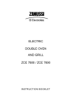
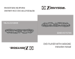
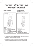
FP-4850HG FLAT PANEL TV MOUNTING SYSTEM
SUPPORT DE TÉLÉVISEUR À ÉCRAN PLAT FP-4850HG
SISTEMA DE INSTALACIÓN DE TV DE PANTALLA PLANA FP-4850HG
ASSEMBLY INSTRUCTIONS
INSTRUCTIONS D’ASSEMBLAGE
INSTRUCCIONES DE ENSAMBLAJE
Patent pending / Brevet en instance / Patent pendiente
Made in China / Fabriqué en Chine / Hecho en China
Italian designed / De design italien / De diseño italiano
Do not discard these instructions / Ne pas jeter ces instructions / Conserve estas instrucciones
M-1_103007v4T
FOR YOUR SAFETY, PLEASE FOLLOW THESE PRECAUTIONS:
! ALWAYS REMOVE THE TV AND OTHER EQUIPMENT FROM THE FURNITURE PRIOR TO MOVING THE ASSEMBLED UNIT.
! BE CAREFUL WHEN MOVING THE ASSEMBLED FURNITURE AFTER THE GLASS SHELF HAS BEEN
INSTALLED, AND/OR WHEN THERE IS EQUIPMENT LOCATED ON THE FURNITURE AS THIS MAY CAUSE
THE SHELVES AND OTHER ITEMS TO BECOME UNSECURED AND FALL.
! WHEN IN USE, THIS FURNITURE MUST BE PLACED ON A FLAT, SOLID AND LEVEL SURFACE.
! DO NOT LEAN ON THE TV WHEN IT IS ON THE TV STAND.
! DO NOT CLIMB OR STEP ON THE STAND.
! DO NOT BANG INTO OR PLACE YOUR OWN WEIGHT ON THE GLASS SHELF.
! DO NOT PLACE ITEMS ON THE SHELVES WHICH EXCEED THE MAXIMUM WEIGHT LIMITS OF 125 LBS. FOR TV
AND 50 LBS. FOR EACH LOWER SHELF. ALWAYS PLACE THE HEAVIEST COMPONENTS ON THE BOTTOM SHELF.
Bell’O International Corp. will not be responsible for failure to assemble as directed or for the improper assembly, use or handling of this stand.
VEILLER À RESPECTER CES MESURES DE PRÉCAUTION !
! TOUJOURS ENLEVER LE TÉLÉVISEUR ET AUTRE ÉQUIPEMENT AVANT DE DÉPLACER LE MEUBLE ASSEMBLÉ.
! DÉPLACER LE MEUBLE AVEC PRÉCAUTION UNE FOIS QUE LE PLATEAU EN VERRE A ÉTÉ POSÉ OU LORSQU'IL Y A DU MATÉRIEL
PLACÉ SUR LE MEUBLE CAR CELA PEUT CAUSER LE DÉCROCHEMENT ET LA CHUTE DES PLATEAUX ET AUTRES ÉLÉMENTS.
! DURANT L’UTILISATION, LE MEUBLE DOIT ÊTRE POSÉ SUR UNE SURFACE PLATE, SOLIDE ET HORIZONTALE.
! NE PAS S’APPUYER CONTRE LE TÉLÉVISEUR LORSQU’IL EST POSÉ SUR LE MEUBLE.
! NE PAS GRIMPER NI MARCHER SUR LE MEUBLE.
! NE PAS TAPER NI S’APPUYER SUR LE PLATEAU EN VERRE.
! NE PAS POSER SUR LE MEUBLE DES OBJETS DÉPASSANT LA LIMITE DE POIDS DE 56,7 KG POUR LE TÉLÉVISEUR ET
DE 22,5 KG POUR CHAQUE PLATEAU INFÉRIEUR. TOUJOURS PLACER LES COMPOSANTS LES PLUS LOURDS SUR LE PLATEAU
INFÉRIEUR.
Bell'O International Corps décline toute responsabilité en cas d'assemblage non conforme aux instructions ou pour l'assemblage,
l'utilisation ou la manutention incorrects de ce meuble.
POR SU SEGURIDAD TENGA LAS SIGUIENTES PRECAUCIONES:
! SIEMPRE QUITE EL TELEVISOR Y CUALQUIER OTRO EQUIPO DEL MUEBLE ANTES DE MOVER LA UNIDAD ARMADA.
! TENGA CUIDADO AL MOVER LA UNIDAD ARMADA UNA VEZ INSTALADO EL ESTANTE DE VIDRIO Y/O CUANDO HAYA ALGÚN
EQUIPO EN EL MUEBLE YA QUE ESTO PODRÍA AFLOJAR EL ESTANTE Y OTROS ARTÍCULOS Y HACER QUE SE CAIGAN.
! EL MUEBLE DEBE ESTAR UBICADO EN UNA SUPERFICIE PLANA, SÓLIDA Y NIVELADA CUANDO SE LO ESTÉ UTILIZANDO.
! NO INCLINE EL TELEVISOR CUANDO ESTÉ EN EL SOPORTE PARA TV.
! NO SE SUBA NI SE PARE SOBRE EL SOPORTE.
! NO GOLPEE EL ESTANTE DE VIDRIO NI SE APOYE CON SU PESO SOBRE EL MISMO.
! NO COLOQUE SOBRE LOS ESTANTES ARTÍCULOS QUE EXCEDAN LOS LÍMITES MÁXIMOS DE PESO: 125 LBS PARA EL TELEVISOR
Y 50 LBS PARA CADA ESTANTE INFERIOR. SIEMPRE COLOQUE LOS COMPONENTES MÁS PESADOS EN EL ESTANTE INFERIOR.
Bell’O International Corp. no se hará responsable en caso de que no se instale la base según las instrucciones,
ni de la instalación, uso o manejo incorrectos de esta base.
PARTS LIST / NOMENCLATURE DES PIÈCES / LISTA DE PIEZAS
Quantity
Quantité
Cantidad
Quantity
Quantité
Cantidad
#
A
1
L
1
B
1
1
4
#
Part / Pièce / Pieza
Part / Pièce / Pieza
FLAT / PLATE / PLANA
60mm
C
1
2
4
D
1
3
4
ROUND / RONDE / REDONDA
E
1
60mm
4
4
2mm
4
H
5
5
18mm
I
2
6
2
J
2
7
4
4mm
K
1
8
10
2
9
2
34"
R
27"
S
2
2
4mm
5mm
STEP 1: STAND ASSEMBLY
ÉTAPE 1 : ASSEMBLAGE DU MEUBLE
PASO 1: ENSAMBLAJE DE LA BASE
NOTE: TWO PEOPLE ARE RECOMMENDED TO ASSEMBLE THIS TABLE.
REMARQUE : IL EST CONSEILLÉ D’ÊTRE À DEUX POUR ASSEMBLER CE MEUBLE.
NOTA: ES RECOMENDABLE ENSAMBLAR ESTA MESA ENTRE DOS PERSONAS
Fig. 1-1
1. PLACE the Bottom Shelf Frame (C) on the floor upside-down, with the four holes in the frame bottom facing upward.
This shelf frame is the same size as the top shelf frame, but has four holes in the underside of the frame.
2. SCREW the four longer-shaft Adjustable Leveling Feet (1) into the Shelf Frame (C) as shown in Fig. 1-1.
1. POSER le cadre de plateau inférieur (C) sur le sol à l'envers, avec les quatre trous dans le dessous du cadre tournés
vers le haut. Ce cadre de plateau est de la même taille que le cadre de plateau supérieur, mais il comporte quatre trous
sur le dessous.
2. VISSER les quatre pieds de niveau réglables à longue tige (1) dans le cadre de plateau (C) comme sur la Fig. 1-1.
1. COLOQUE el marco del estante inferior (C) al revés en el piso, con los cuatro orificios de la parte inferior del marco
mirando hacia arriba. Este marco de estante es del mismo tamaño que el marco del estante superior, pero tiene cuatro
orificios en la parte inferior del marco.
2. ATORNILLE las cuatro patas niveladoras ajustables de eje más largo (1) en el marco del estante (C), tal como se
indica en la Fig. 1-1.
3. SCREW four short Adjustable Feet (3) into the holes located on the bottom
of the Left & Right Stabilizing Brackets (D & E) as shown in Fig. 1-2A.
Fig. 1-2
4. PLACE the Flat Panel Mounting System Post (A) upright as shown. Working
from the rear, PLACE the Left & Right Stabilizing Brackets (D & E) up
against the rear of the Mounting System Post's base as shown in Fig. 1-2.
5. SECURE the Bottom Shelf Frame (C) to the Mounting System Post (A) by
inserting four FLAT HEAD 60mm Bolts (2) through the Stabilizing Brackets
(D & E) as shown in Fig. 1-2 & 1-2A. Tighten fully using the supplied Allen
wrench.
6. SECURE the Top Shelf
Frame (B) to the Mounting
System Post (A) using four
ROUND HEAD 60mm Bolts
(4) as shown in Fig. 1-2.
Tighten fully using the
supplied Allen wrench.
NOTE: The top shelf frame
is the same size as the
bottom shelf frame, but
does not have the four
holes in the bottom of the
shelf.
Fig. 1-2A
3. VISSER les quatre pieds réglages courts (3) dans les trous à la base des ferrures de stabilisation gauche et droite (D et E)
comme sur la Fig. 1-2A.
4. POSER le montant support d'écran plat (A) verticalement sur l'illustration. En travaillant depuis l'arrière, PLACER les ferrures
de stabilisation gauche et droite (D et E) contre l'arrière du bas du montant support, comme sur la Fig. 1-2.
5. ATTACHER cadre de plateau inférieur (C) au montant support (A) en introduisant quatre boulons à TÊTE PLATE de 60 mm (2)
à travers les ferrures de stabilisation (D et E), comme sur les Fig. 1-2 et 1-2A. Serrer complètement avec la clé Allen fournie.
6. ATTACHER le cadre de plateau supérieur (B) au montant support (A) avec quatre boulons à TÊTE RONDE de 60 mm (4)
comme sur la Fig. 1-2. Serrer complètement avec la clé Allen fournie. REMARQUE : Le cadre de plateau supérieur est de la
même taille que le cadre de plateau inférieur, mais ne comporte pas les quatre trous sur le dessous.
3. ATORNILLE cuatro patas ajustables cortas (3) en los orificios ubicados en la parte inferior de los soportes estabilizadores
derecho e izquierdo (D y E) tal como se indica en la Fig. 1-2A.
4. COLOQUE el sostén del sistema de instalación de TV de pantalla plana (A) en posición vertical, tal como se indica. Desde la
parte trasera, COLOQUE los soportes estabilizadores derecho e izquierdo (D & E) contra la parte trasera de la base del sostén
del sistema de instalación, tal como se indica en la Fig. 1-2.
5. ASEGURE el marco del estante inferior (C) al sostén del sistema de instalación (A) insertando cuatro pernos de CABEZA
PLANA de 60 mm (2) a través de los soportes estabilizadores (D y E), tal como se indica en las Fig. 1-2 y 1-2A. Ajuste bien
utilizando la llave Allen incluida.
6. ASEGURE el marco del estante superior (B) al sostén de sistema de instalación (A) utilizando cuatro pernos de CABEZA
REDONDA de 60 mm (4), tal como se indica en la Fig. 1-2. Ajuste bien utilizando la llave Allen incluida. NOTA: El marco del
estante superior tiene el mismo tamaño que el marco del estante inferior, pero no tiene los cuatro orificios en la parte inferior
del estante.
7. PLACE five Small Glass Pads (5) onto the
Bottom Shelf Frame (C). (Place three along the
front, and two along the rear).
Fig. 1-3
8. PLACE two Large Pads (8) onto the REAR bars
of the Top Shelf Frame (B).
9. INSERT the two CMS® (Cable Management
System) Covers (J) into the vertical slots located
in the rear of the Flat Panel Mounting System
Post (A).You can easily manage and hide
unsightly wires and cables of the TV and other
components by removing these covers, running
the cables, then re-attaching the covers.
10. MOVE the stand to the location it will occupy
when fully assembled and in use.
NOTE: Use the Adjustable Feet (3) to ensure that
the furniture is level on the floor before
attempting to mount the television.
7. PLACER cinq petits tampons
d'appui (5) sur le cadre de plateau
inférieur (C) (trois sur la partie avant,
deux à l'arrière).
8. PLACER deux grands tampons d'appui (8)
sur les barres ARRIÈRE du cadre de plateau
supérieur (B).
9. INTRODUIRE les deux capots passe-fil CMS® (J) dans les encoches verticales à l'arrière du montant support d'écran plat (A).
Pour gérer et dissimuler aisément les fils et câbles du téléviseur et autres appareils, il suffit d'enlever ces capots, d'y faire
passer les câbles puis de remettre les capots en place.
10. DÉPLACER le meuble jusqu'à l'emplacement qu'il doit occuper une fois assemblé, lors de son utilisation.
REMARQUE : Utiliser les pieds réglables (3) pour assurer que le meuble est de niveau sur le sol avant de tenter de poser le
téléviseur.
7. COLOQUE cinco pequeñas almohadillas para vidrio (5) en el marco del estante inferior (C). (Coloque tres a lo largo del frente
y dos a lo largo de la parte trasera).
8. COLOQUE dos almohadillas grandes (8) en las barras TRASERAS del marco del estante superior (B).
9. INSERTE las dos cubiertas (J) del CMS® (Sistema de administración de cables) en las ranuras verticales ubicadas en la parte
trasera del sostén del sistema de instalación de TV de pantalla plana (A). Puede organizar y ocultar fácilmente alambres y
cables antiestéticos del TV y otros componentes retirando estas cubiertas, pasando los cables y colocando nuevamente las
cubiertas.
10. MUEVA la base hacia el lugar que ocupará cuando esté totalmente ensamblada y en uso.
NOTA: utilice las patas ajustables (3) para asegurarse de que el mueble esté nivelado en el piso antes de intentar instalar el
televisor.
STEP 2: MOUNTING THE TELEVISION
ÉTAPE 2 : POSE DU TÉLÉVISEUR
PASO 2: INSTALACIÓN DEL TELEVISOR
CAUTION: CAREFULLY DETERMINE THE CORRECT MOUNTING PROCEDURE TO PREVENT DAMAGE TO YOUR TV AND/OR BELL'O® MOUNTING
SYSTEM. ALWAYS REMOVE THE TELEVISION & COMPONENTS BEFORE ATTEMPTING TO MOVE THE STAND.
ATTENTION : DÉTERMINER AVEC ATTENTION LA PROCÉDURE DE POSE CORRECTE POUR ÉVITER D'ENDOMMAGER LE TÉLÉVISEUR OU LE SYSTÈME DE
FIXATION BELL'O®. VEILLER À TOUJOURS ENLEVER LE TÉLÉVISEUR ET AUTRES APPAREILS AVANT DE TENTER DE DÉPLACER LE MEUBLE.
ADVERTENCIA: DETERMINE CON CUIDADO CUÁL ES EL PROCEDIMIENTO CORRECTO DE INSTALACIÓN PARA EVITAR DAÑAR SU TV O EL
SISTEMA DE INSTALACIÓN BELL'O®.SIEMPRE DEBE SACAR EL TELEVISOR Y LOS COMPONENTES ANTES DE INTENTAR MOVER LA BASE.
1
DETERMINE YOUR TELEVISION'S MOUNTING CONFIGURATION.
DÉTERMINER LA CONFIGURATION DE FIXATION DU TÉLÉVISEUR.
DETERMINE LA CONFIGURACIÓN DE INSTALACIÓN DE SU TELEVISOR.
HOLE SPACING
ESPACEMENT DES TROUS
ESPACIO ENTRE ORIFICIOS
BACK OF TV / DOS DU TÉLÉVISEUR / PARTE TRASERA DEL TV
Most mounting hole spacing dimensions are listed by the TV manufacturers in millimeters (mm).
Listed below are some sizes that are either standards, or are commonly used in the industry:
(A x B):
• 75 x 75mm
• 100 x 100mm
• 200 x 100mm
• 200 x 150mm
• 200 x 200mm
• 300 x 200mm
• 400 x 200mm
• 400 x 300mm
• 600 x 400mm
• 800 x 400mm
For additional help, refer to your manufacturer’s TV/Monitor Users Manual.
La majorité des dimensions d'espacement des trous de fixation sont fournies par les fabricants de téléviseur en millimètres (mm).
La liste ci-dessous indique des dimensions qui sont soit normalisées, soit couramment utilisées dans l'industrie:
(A x B):
• 75 x 75mm
• 100 x 100mm
• 200 x 100mm
• 200 x 150mm
• 200 x 200mm
• 300 x 200mm
• 400 x 200mm
• 400 x 300mm
• 600 x 400mm
• 800 x 400mm
Pour de plus amples renseignements, consulter le mode d'emploi du téléviseur/moniteur.
Los fabricantes de televisores incluyen la mayoría de las dimensiones de espacios entre orificios de instalación en milímetros (mm).
Más abajo, encontrará algunos tamaños que corresponden al estándar o se utilizan con frecuencia en la industria:
(A x B):
• 75 x 75mm
• 100 x 100mm
• 200 x 100mm
• 200 x 150mm
• 200 x 200mm
• 300 x 200mm
• 400 x 200mm
• 400 x 300mm
Para más ayuda, consulte el manual del usuario del fabricante de su TV o monitor.
• 600 x 400mm
• 800 x 400mm
2
SELECT THE CORRECT ASSEMBLY PROCEDURE FOR YOUR TELEVISION.
SÉLECTIONNER LA PROCÉDURE D'ASSEMBLAGE CORRECTE POUR LE TÉLÉVISEUR.
ELIJA EL PROCEDIMIENTO DE ENSAMBLAJE ADECUADO PARA SU TELEVISOR.
IF YOUR HOLE MOUNTING
CONFIGURATION IS:
75 x 75mm
100 x 100mm
200 x 100mm
200 x 150mm
FOLLOW THE APPROPRIATE ASSEMBLY PROCEDURE:
ONLY THE MOUNTING BRACKETS (R OR S) ARE REQUIRED
TO COMPLETE ASSEMBLY OF STAND.
FOLLOW PROCEDURE FOR TV MOUNTING ON: PAGE 9
200 x 200mm
400 x 200mm
400 x 300mm
MOUNTING BRACKETS (R OR S) AND 300MM ADAPTERS (H) ARE
REQUIRED TO COMPLETE ASSEMBLY OF STAND.
FOLLOW PROCEDURE FOR TV MOUNTING ON: PAGE 10
300 x 200mm
300 x 300mm
MOUNTING BRACKETS (R OR S) AND UNIVERSAL FLAT PANEL BARS (I)
ARE REQUIRED TO COMPLETE ASSEMBLY OF STAND.
600 x 400mm
800 x 400mm
FOLLOW PROCEDURE FOR TV MOUNTING ON:
SI LA CONFIGURATION DES
TROUS DE FIXATION EST :
75 x 75mm
100 x 100mm
200 x 100mm
200 x 150mm
PAGES 11 & 12
SUIVRE LA PROCÉDURE DE FIXATION CORRESPONDANTE :
SEULS LES SUPPORTS DE FIXATION (R OU S) SONT NÉCESSAIRES
POUR ACHEVER L'ASSEMBLAGE DU MEUBLE.
200 x 200mm
400 x 200mm
400 x 300mm
SUIVRE LA PROCÉDURE DE POSE DU TÉLÉVISEUR : PAGE
9
300 x 200mm
300 x 300mm
LES SUPPORTS DE FIXATION (R OU S) ET LES ADAPTATEURS DE 300 MM
(H) SONT NÉCESSAIRES POUR ACHEVER L'ASSEMBLAGE DU MEUBLE.
SUIVRE LA PROCÉDURE DE POSE DU TÉLÉVISEUR : PAGE 10
600 x 400mm
800 x 400mm
LES SUPPORTS DE FIXATION (R OU S) ET LES BARRES POUR
ÉCRAN PLAT UNIVERSELLES (I) SONT NÉCESSAIRES POUR
ACHEVER L'ASSEMBLAGE DU MEUBLE. SUIVRE LA PROCÉDURE
DE POSE DU TÉLÉVISEUR : PAGES 11 ET 12
SI SU CONFIGURACIÓN DE
ORIFICIOS DE INSTALACIÓN ES:
75 x 75mm
100 x 100mm
200 x 100mm
200 x 150mm
200 x 200mm
400 x 200mm
400 x 300mm
SIGA EL PROCEDIMIENTO DE ENSAMBLAJE ADECUADO:
SÓLO SE NECESITAN LOS SOPORTES DE INSTALACIÓN (R O S) PARA
CULMINAR EL ENSAMBLAJE DE LA BASE. SIGA EL PROCEDIMIENTO
PARA LA INSTALACIÓN DEL TV EN LA:
PÁGINA 9
300 x 200mm
300 x 300mm
SE NECESITAN LOS SOPORTES DE INSTALACIÓN (R O S) Y LOS ADAPTADORES DE
300 MM (H) PARA CULMINAR EL ENSAMBLAJE DE LA BASE. SIGA EL PROCEDIMIENTO
PARA LA INSTALACIÓN DEL TV EN LA: PÁGINA 10
600 x 400mm
800 x 400mm
SE NECESITAN LOS SOPORTES DE INSTALACIÓN (R O S) Y LAS
BARRAS UNIVERSALES PARA PANTALLA PLANA (I) PARA CULMINAR EL
ENSAMBLAJE DE LA BASE. SIGA EL PROCEDIMIENTO PARA LA
INSTALACIÓN DEL TV EN LAS: PÁGINAS 11 & 12
MOUNTING THE TV WITH MOUNTING BRACKETS ONLY
POSE DU TÉLÉVISEUR AVEC LES SUPPORTS DE FIXATION SEULEMENT
INSTALACIÓN DEL TV SÓLO CON LOS SOPORTES DE INSTALACIÓN
THE MOUNTING BRACKETS (R OR S) ALONE CAN ACCOMMODATE MOST TELEVISION MOUNTING CONFIGURATIONS. FOR TV'S WITH A 300mm WIDE
CONFIGURATION, REFER TO PAGE 9. FOR TV'S WITH A MOUNTING CONFIGURATION TALLER THAN 400mm, REFER TO PAGES 10 & 11. DO NOT EXCEED 125 LBS.
LES SUPPORTS DE FIXATION (R OU S) SEULS SONT COMPATIBLES AVEC LA MAJORITÉ DES CONFIGURATIONS DE FIXATION DE TÉLÉVISEUR. POUR LES TÉLÉVISEURS À ESPACEMENT DE 300
MM EN LARGEUR, SE REPORTER À LA PAGE 9. POUR LES TÉLÉVISEURS À ESPACEMENT DE PLUS DE 400 MM EN HAUTEUR, SE REPORTER AUX PAGES 10 ET 11. NE PAS DÉPASSER 57 KG.
LOS SOPORTES DE INSTALACIÓN (R O S) POR SÍ SOLOS PUEDEN ADAPTARSE A LA MAYORÍA DE LAS CONFIGURACIONES DE INSTALACIÓN DEL TELEVISOR. PARA LOS
TELEVISORES CON UNA CONFIGURACIÓN DE UN ANCHO DE 300 MM, CONSULTE LA PÁGINA 9. PARA LOS TELEVISORES CON UNA CONFIGURACIÓN DE INSTALACIÓN DE UNA
ALTURA SUPERIOR A LOS 400 MM, CONSULTE LAS PÁGINAS 10 Y 11. NO EXCEDA LAS 125 LB.
1. PLACE your TV face-down on a very soft, non-abrasive surface, taking extreme caution to not
damage the face of your TV.
2. Determine the correct size screws and washers for mounting your television from the screws
and washers included with your TV, or in your stand's hardware pack.
Fig. 2-1
3. ALIGN the pair of Mounting Brackets (R or S) that best fits the size of your TV to the mounting
holes on the back of your television.
4. Make sure the Mounting Brackets are centered on the back of your TV and install all screws
and washers as shown in Fig. 2-1. Tighten fully.
5. Before attaching the TV, first make sure the adjustable screws located at the top of the Flat
Panel Mounting System Post (A) are extended approx. 3/8" to allow for the Mounting Bracket
hooks as shown in Fig. 2-2A.
6. USING TWO PEOPLE TO HOLD THE TV, ATTACH the Mounting Bars onto the adjustable
screws located in the Flat Panel Mounting System Post as shown in Figs. 2-2 & 2-2A.
Apply gentle downward force to properly install over screws.
7. TIGHTEN all adjustable screws completely to secure TV to stand.
1. POSER le téléviseur à plat sur sa face avant sur une surface très douce et non
abrasive, en faisant preuve de précaution extrême pour ne pas l'endommager.
R or S
2. Déterminer la taille de vis et de rondelles correcte pour fixer le téléviseur parmi les vis et rondelles
fournies avec le téléviseur ou dans le sachet de visserie du meuble.
3. ALIGNER la paire de supports de fixation (R ou S) qui convient le mieux pour les trous de fixation au dos du téléviseur.
4. S'assurer que les supports de fixation sont centrés au dos du téléviseur et poser toutes les vis et rondelles comme sur la Fig. 2-1. Serrer complètement.
5. Avant d'accrocher le téléviseur, s'assurer d'abord que les vis réglables au sommet du montant support d'écran plat (A) dépassent de 10 mm environ pour
permettre le passage des crochets du support de fixation comme sur la Fig. 2-2A.
6. LE TÉLÉVISEUR ÉTANT PORTÉ PAR DEUX PERSONNES, ACCROCHER les barres de fixation aux vis réglables placées dans le montant support
d'écran plat comme sur les Fig. 2-2 & 2-2A. Appuyer doucement vers le bas pour les engager complètement sur les vis.
7. SERRER complètement toutes les vis réglables pour fixer le téléviseur au meuble.
Fig. 2-2
1. COLOQUE su TV boca abajo en una superficie muy suave y que no sea abrasiva, tomando todas las
precauciones para no dañar la parte frontal de su TV.
2. Elija el tamaño correcto de los tornillos y las arandelas que necesita para instalar su televisor
entre los tornillos y las arandelas incluidos con su TV o en el paquete de
hardware de su base.
3. ALINEE el par de soportes de instalación (R o S) que mejor se adapte al
tamaño de su TV con los orificios de instalación que se encuentran en la
parte trasera de su televisor.
4. Asegúrese de que los soportes de instalación estén centrados en la
parte trasera de su televisor e instale todos los tornillos y las
arandelas, tal como se indica en la Fig. 2-1. Ajuste bien.
5. Antes del colocar el TV, asegúrese de que los tornillos ajustables
ubicados en la parte superior del sostén del sistema de instalación de
pantalla plana (A) estén extendidos aproximadamente 3/8" para darle
espacio a los ganchos del soporte de instalación, tal como se indica en la
Fig. 2-2A.
Fig. 2-2A
6. UTILIZANDO DOS PERSONAS PARA SOSTENER EL TV, COLOQUE las barras de
instalación en los tornillos ajustables ubicados en el sostén del sistema de instalación de
pantalla plana, tal como se indica en las Figuras 2-2 y 2-2A. Aplique una fuerza moderada hacia
abajo para instalar adecuadamente sobre los tornillos.
7. AJUSTE bien todos los tornillos ajustables para fijar el TV a la base.
MOUNTING THE TV WITH MOUNTING BRACKETS AND 300MM ADAPTERS
POSE DU TÉLÉVISEUR AVEC LES SUPPORTS DE FIXATION ET LES ADAPTATEURS DE 300 MM
INSTALACIÓN DEL TV CON SOPORTES DE INSTALACIÓN Y ADAPTADORES DE 300 MM
USE ADAPTERS (H) FOR TELEVISIONS WITH A 300mm WIDE MOUNTING CONFIGURATION ONLY. DO NOT EXCEED 125 LBS.
UTILISER LES ADAPTATEURS (H) SUR LES TÉLÉVISEURS À CONFIGURATION DE 300 MM DE LARGE UNIQUEMENT. NE PAS DÉPASSER 57 KG.
UTILICE ADAPTADORES (H) SÓLO PARA TELEVISORES CON UNA CONFIGURACIÓN DE INSTALACIÓN DE 300 MM DE ANCHO. NO EXCEDA LAS 125 LB.
1. PLACE your TV face-down on a very soft, non-abrasive surface, taking extreme caution to not damage the
face of your TV.
Fig. 2-1
2. Determine the correct size screws and washers for mounting your television from the screws and washers
included with your TV or in your stand's hardware pack.
3. ATTACH four 300mm Adapters to the back of your TV as shown in Fig. 2-1. Tighten all screws fully.
4. ATTACH the proper size Mounting Bars (R or S) to the 300mm Adapters as shown in Fig. 2-2. Tighten all
Thumb Wheel Nuts (7) completely.
5. Before attaching the TV, first make sure the adjustable screws located at the top of the Flat Panel
Mounting System Post (A) are extended approx. 3/8" to allow for the Mounting Bracket hooks as shown in
Fig. 2-3A.
6. USING TWO PEOPLE TO HOLD THE TV, ATTACH the Mounting Bars onto the adjustable screws located
in the Flat Panel Mounting System Post as shown in Figs. 2-3 & 2-3A. Apply gentle downward force to
properly install over screws.
7. TIGHTEN all adjustable screws completely to secure TV to stand.
1. POSER le téléviseur à plat sur sa face avant sur une surface très douce et non abrasive, en faisant
preuve de précaution extrême pour ne pas l'endommager.
Fig. 2-2
2. Déterminer la taille de vis et de rondelles correcte pour fixer le téléviseur parmi les vis et rondelles
fournies avec le téléviseur ou dans le sachet de visserie du meuble.
3. FIXER quatre adaptateurs de 300 mm au dos du téléviseur comme sur la Fig. 2-1. Serrer complètement toutes les vis.
4. FIXER les barres de fixation (R ou S) de taille adaptée aux adaptateurs de 300 mm comme sur la
Fig. 2-2. Serrer complètement tous les écrous moletés (7).
5. Avant d'accrocher le téléviseur, s'assurer d'abord que les vis réglables au sommet du montant support
d'écran plat (A) dépassent de 10 mm environ pour permettre le passage des crochets du support de
fixation comme sur la Fig. 2-3A.
6. LE TÉLÉVISEUR ÉTANT PORTÉ PAR DEUX PERSONNES, ACCROCHER les barres de fixation aux
vis réglables placées dans le montant support d'écran plat comme sur les Fig. 2-3 & 2-3A. Appuyer
doucement vers le bas pour les engager complètement sur les vis.
7. SERRER complètement toutes les vis réglables pour fixer le téléviseur au meuble.
Fig. 2-3
1. COLOQUE su TV boca abajo en una superficie muy suave y que no sea abrasiva, tomando todas las precauciones
para no dañar la parte frontal de su TV.
2. Elija el tamaño correcto de los tornillos y las arandelas que necesita para instalar su televisor entre los
tornillos y arandelas incluidos con su TV o en el paquete de hardware de su base.
3. COLOQUE cuatro adaptadores de 300 mm en la parte trasera de su TV, tal
como se indica en la Fig. 2-1. Ajuste bien todos los tornillos.
4. COLOQUE las barras de instalación del tamaño adecuado (R o S) en los
adaptadores de 300 mm, tal como se indica en la Fig. 2-2.
Ajuste bien todas las tuercas de ajuste con el pulgar (7).
5. Antes del colocar el TV, asegúrese de que los tornillos ajustables
ubicados en la parte superior del sostén del sistema de instalación de
pantalla plana (A) estén extendidos aproximadamente 3/8" para darle espacio
a los ganchos del soporte de instalación, tal como se indica en la Fig. 2-3A.
Fig. 2-3A
6. UTILIZANDO DOS PERSONAS PARA SOSTENER EL TV, COLOQUE las
barras de instalación en los tornillos ajustables ubicados en el sostén del sistema
de instalación de pantalla plana, tal como se indica en las Figuras 2-3 y 2-3A. Aplique una fuerza moderada
hacia abajo para instalar adecuadamente sobre los tornillos.
7. AJUSTE bien todos los tornillos ajustables para fijar el TV a la base.
MOUNTING THE TV WITH MOUNTING BRACKETS AND UNIVERSAL FLAT PANEL BARS
POSE DU TÉLÉVISEUR AVEC LES SUPPORTS DE FIXATION ET LES BARRES POUR ÉCRAN PLAT UNIVERSELLES
INSTALACIÓN DEL TV CON SOPORTES DE INSTALACIÓN Y BARRAS UNIVERSALES PARA PANTALLA PLANA
ONLY USE UNIVERSAL FLAT PANEL BARS (I) WITH THE MOUNTING BRACKETS (R OR S) FOR TELEVISIONS WITH A MOUNTING CONFIGURATION
TALLER THAN 300mm. DO NOT EXCEED 125 LBS.
UTILISER LES BARRES POUR ÉCRAN PLAT UNIVERSELLES (I) AVEC LES SUPPORTS DE FIXATION (R OU S) UNIQUEMENT SUR LES TÉLÉVISEURS À
CONFIGURATION DE PLUS DE 300 MM DE HAUT. NE PAS DÉPASSER 57 KG.
UTILICE ÚNICAMENTE BARRAS UNIVERSALES PARA PANTALLA PLANA (I) CON LOS SOPORTES DE INSTALACIÓN (R O S) PARA TELEVISORES CON UNA
CONFIGURACIÓN DE INSTALACIÓN DE UNA ALTURA SUPERIOR A LOS 300 MM. NO EXCEDA LAS 125 LB.
1. ATTACH four Large Pads (8) to the FRONT sides of each Universal Flat
Panel Bar (I) where indicated in Fig. 2-1. The Pads will help to
protect your TV cabinet.
Fig. 2-1
NOTE: The FRONT side of the Universal Flat Panel Bar does NOT have
the protruding screw.
2. CONNECT the Universal Flat Panel Bars (I) to the pair of Mounting
Brackets (R or S) that best fits your size television as shown in Fig. 2-2.
Use two 18mm screws (6) to connect the BOTTOM Mounting Bracket to
the bottom slot of the Universal Flat Panel Bars. DO NOT YET FULLY
TIGHTEN the four Thumb Wheel Nuts (7).
1. FIXER quatre grands tampons d'appui (8) sur la face AVANT de chaque
barre universelle (I) comme indiqué sur la Fig. 2-1. Les
tampons servent à protéger le boîtier du téléviseur.
REMARQUE : La face AVANT des barres pour écran plat universelles ne
comporte PAS la vis en saillie.
2. RACCORDER les barres pour écran plat universelles (I) à la paire de
supports de fixation (R ou S) qui convient le mieux pour la taille du
téléviseur comme sur la Fig. 2-1. Avec deux vis de 18 mm (6), raccorder
le support de fixation INFÉRIEUR au trou oblong inférieur des barres
pour écran plat universelles. NE PAS ENCORE SERRER
COMPLÈTEMENT les quatre écrous à molette (7).
Fig. 2-2
1. COLOQUE cuatro almohadillas grandes (8) a los costados
FRONTALES de cada barra universal para pantalla plana (I) donde
indica la Fig. 1. Las almohadillas ayudarán a proteger el gabinete
de su TV.
NOTA: La parte FRONTAL de la barra universal para pantalla plana
NO tiene el tornillo sobresaliente.
2. CONECTE las barras universales de pantalla plana (I) al par de
soportes de instalación (R o S) que mejor se adapten al tamaño de
su televisor, tal como se indica en la Fig. 2-2. Utilice dos tornillos de
18 mm (6) para conectar el soporte de instalación INFERIOR a la
ranura inferior de las barras universales de pantalla plana. AÚN NO
AJUSTE COMPLETAMENTE las cuatro tuercas de ajuste con el
pulgar (7).
MOUNTING THE TV WITH MOUNTING BRACKETS AND UNIVERSAL FLAT PANEL BARS (CONTINUED)
POSE DU TÉLÉVISEUR AVEC LES SUPPORTS DE FIXATION ET LES BARRES POUR ÉCRAN PLAT UNIVERSELLES (SUITE)
MOUNTING THE TV WITH MOUNTING BRACKETS AND UNIVERSAL FLAT PANEL BARS (CONTINUED)
3. PLACE your TV face-down on a very soft, non-abrasive surface, taking
extreme caution to not damage the face of your TV.
Fig. 2-3
4. Determine the correct size screws and washers for mounting your
television from the screws and washers included with your TV or in your
stand's hardware pack.
5. ATTACH the Mounting Brackets/Universal Flat Panel Bars assembly to the
back of your TV. Align the mounting holes in the TV with the slots in the
bracket assembly and install the screws and washers as shown in Fig. 2-3.
6. Make sure the bracket assembly is properly aligned and centered, then
FULLY TIGHTEN ALL Thumb Wheel Nuts (7) and screws.
7. Before attaching the TV, first make sure the adjustable screws located at
the top of the Flat Panel Mounting System Post (A) are extended approx.
3/8" to allow for the Mounting Bracket hooks as shown in Fig. 2-4A.
8. USING TWO PEOPLE TO HOLD THE TV, ATTACH the Mounting Bars
onto the adjustable screws located in the Flat Panel Mounting System Post
as shown in Figs. 2-4 & 2-4A. Apply gentle downward force to properly
install over screws.
9. TIGHTEN ALL adjustable screws completely to secure TV.
3. POSER le téléviseur à plat sur sa face avant sur une surface très douce et non abrasive, en faisant preuve de précaution extrême pour ne pas
l'endommager.
4. Déterminer la taille de vis et de rondelles correcte pour fixer le téléviseur parmi les vis et rondelles fournies avec le téléviseur ou dans le sachet
de visserie du meuble.
5. FIXER l'ensemble supports de fixation/barres pour écran plat universelles au dos du téléviseur. Aligner les trous de fixation du téléviseur avec les
trous oblongs dans les supports et poser les vis et les rondelles comme sur la Fig. 2-3.
6. S'assurer que le support est correctement aligné et centré, puis SERRER COMPLÈTEMENT TOUS les écrous moletés (7) et les vis.
7. Avant d'accrocher le téléviseur, s'assurer d'abord que les vis réglables au sommet du montant support d'écran plat (A) dépassent de 10 mm
environ pour permettre le passage des crochets du support de fixation comme sur la Fig. 2-4A.
8. LE TÉLÉVISEUR ÉTANT PORTÉ PAR DEUX PERSONNES, ACCROCHER les barres de fixation aux vis réglables placées dans le montant
support d'écran plat comme sur les Fig. 2-4 & 2-4A. Appuyer doucement vers le bas pour les engager complètement sur les vis.
9. SERRER complètement toutes les vis réglables pour fixer le téléviseur.
3. COLOQUE su TV boca abajo en una superficie muy suave y que no sea abrasiva, tomando todas las
precauciones para no dañar la parte frontal de su TV.
4. Elija el tamaño correcto de los tornillos y las arandelas que necesita para instalar su televisor entre los
tornillos y arandelas incluidos con su TV o en el paquete de hardware de su base.
5. COLOQUE los soportes de instalación o el ensamblaje de las barras universales para pantalla
plana en la parte trasera de su TV. Alinee los orificios de instalación del TV
con las ranuras en el ensamblaje del sostén y coloque los tornillos y
las arandelas, tal como se indica en la Fig. 2-3.
6. Asegúrese de que el ensamblaje del sostén esté alineado y
centrado adecuadamente, luego AJUSTE BIEN TODAS las
tuercas de ajuste con el pulgar (7) y los tornillos.
7. Antes del colocar el TV, asegúrese de que los tornillos
ajustables ubicados en la parte superior del sostén del
sistema de instalación de pantalla plana (A) estén extendidos
aproximadamente 3/8" para darle espacio a los ganchos del
soporte de instalación, tal como se indica en la Fig. 2-4A.
Fig. 2-4A
8. UTILIZANDO DOS PERSONAS PARA SOSTENER EL TV,
COLOQUE las barras de instalación en los tornillos ajustables
ubicados en el sostén del sistema de instalación de pantalla plana, tal
como se indica en las Figuras 2-4 y 2-4A. Aplique una fuerza moderada hacia abajo para
instalar adecuadamente sobre los tornillos.
9. AJUSTE bien todos los tornillos ajustables para fijar el TV.
Fig. 2-4
STEP 3: INSTALL THE GLASS SHELVES
ÉTAPE 3 : POSE DES PLATEAUX EN VERRE
PASO 3: INSTALACIÓN DE LOS ESTANTES DE VIDRIO
CAUTION: ALWAYS REMOVE THE GLASS SHELVES BEFORE ATTACHING/REMOVING YOUR TELEVISION, OR BEFORE ATTEMPTING TO MOVE THE STAND.
ATTENTION : VEILLER À TOUJOURS ENLEVER LES PLATEAUX EN VERRE AVANT D'ACCROCHER/DÉCROCHER LE TÉLÉVISEUR OU DE TENTER DE DÉPLACER LE MEUBLE.
ADVERTENCIA:SIEMPRE DEBE SACAR LOS ESTANTES DE VIDRIO ANTES DE COLOCAR O SACAR SU TELEVISOR O ANTES DE INTENTAR MOVER LA BASE.
1. CAREFULLY PLACE the Bottom Glass Shelf (L) onto the Bottom Shelf
Frame (C) and SLIDE the edge with the hole through the slot in the CMS®
panel.
Fig. 3-1
NOTE: The Bottom Glass Shelf (L) is the larger of the two shelves.
2. CAREFULLY PLACE the Top Glass Shelf (K), onto the top shelf frame (B)
and SLIDE the edge with the hole through the slot in the curved CMS®
panel.
NOTE: Three Adjustable Glass Levelers are preinstalled in the Top Shelf
Frame (B). It is important that these are properly adjusted to
support the Top Glass Shelf (K) and to keep it level. TURN each
Adjustable Glass Leveler clockwise or counter-clockwise to adjust.
ALWAYS MAKE SURE THE TOP GLASS SHELF IS LEVEL
BEFORE PLACING ANY ITEMS ON IT.
3. Working from the rear of the assembly, PLACE two plastic T-Pins (9)
through the rear holes in the two Glass Shelves to help prevent the
shelves from falling out of place.
1. AVEC PRÉCAUTION, POSER le plateau en verre inférieur (L) sur le cadre de plateau inférieur (C) et
ENFILER le bord comportant le trou à travers la rainure dans le panneau CMS®.
REMARQUE : Le plateau en verre inférieur (L) est le plus grand des deux plateaux.
2. AVEC PRÉCAUTION, POSER le plateau en verre supérieur (K) sur le cadre de plateau supérieur (B) et ENFILER le bord comportant le trou à travers
la rainure dans le panneau CMS® bombé.
REMARQUE : Le cadre de plateau supérieur (B) comporte trois vérins de plateau réglables préinstallés. Il est important de les régler correctement pour bien
soutenir le plateau en verre supérieur (K) et le maintenir horizontal. TOURNER chaque vérin de plateau réglable dans un sens ou dans
l'autre pour le régler. TOUJOURS S'ASSURER QUE LE PLATEAU EN VERRE EST HORIZONTAL AVANT D'Y POSER DES OBJETS.
3. En travaillant depuis l'arrière de l'assemblage, POSER deux broches en T en plastique (9) à travers les trous arrière des deux plateaux en verre
pour bloquer leur déplacement.
1. COLOQUE CUIDADOSAMENTE el estante de vidrio inferior (L) sobre el marco del estante
inferior (C) y DESLICE el borde con el orificio a través de la ranura que se encuentra en el
panel del CMS®.
NOTA: El estante de vidrio inferior (L) es el más grande de los dos estantes.
2. COLOQUE CUIDADOSAMENTE el estante de vidrio superior (K) sobre el marco del
estante superior (B) y DESLICE el borde con el orificio a través de la ranura que se
encuentra en el panel curvo del CMS®.
NOTA: Tres niveladores de vidrio ajustables están preinstalados en el marco del estante
superior (B). Es importante que éstos estén ajustados adecuadamente para darle
apoyo al estante de vidrio superior (K) y mantenerlo nivelado. GIRE cada
nivelador de vidrio ajustable en el sentido de las agujas del reloj o en sentido
contrario a las agujas del reloj para regular. SIEMPRE ASEGÚRESE DE QUE
EL ESTANTE DE VIDRIO SUPERIOR ESTÉ NIVELADO ANTES DE PONER
CUALQUIER ARTÍCULO ENCIMA.
3. Desde la parte trasera del ensamblaje, COLOQUE dos clavijas plásticas en forma
de T (9) a través de los orificios traseros de los dos estantes de vidrio para ayudar
a evitar que los estantes se salgan de su lugar.
Fig. 3-2
Warranty
One (1) Year Limited Warranty
All Bell’O International products are warranted, with the exception of glass, to the original purchaser at the time of
purchase and for a period of one (1) year thereafter. Glass is warranted to the original purchaser at the time of
purchase and for a period of thirty (30) days thereafter. Warranty is only valid in the United States of America.
In order to provide you with timely assistance, please thoroughly inspect your furniture for missing or defective parts
immediately after opening the carton. To receive replacement or missing part(s) under this warranty, go to our
website at www.bello.com or call our Customer Service Department at 1-888-235-7646. Please have the model
number and part number(s) for reference. You will also need your sales receipt or other proof of purchase.
Replacement part(s) will be shipped to you at no charge with Bell’O International assuming all shipping and handling
expense.
We warrant to you, the original purchaser, that our furniture and all of its parts and components are free of defects in
material or workmanship. "Defects", as used in this warranty, is defined as any imperfections that impair the use of
the furniture or product.
Our warranty is expressly limited to the replacement of furniture parts and components. For one (1) year after the
date of purchase, Bell’O International will replace any part described on the enclosed furniture parts list that is
defective in material or workmanship.
This warranty applies under conditions of normal use. Our furniture products are not intended for outdoor use. The
warranty does not cover: 1) defects caused by improper assembly or disassembly; 2) defects caused by shipping,
claims for damage during transit to you should be placed immediately by you to the transportation company;
3) defects occurring after purchase due to product modification, intentional damage, accident, misuse, abuse,
negligence or exposure to the elements; 4) cosmetic damage and 5) labor or assembly costs.
There are no warranties, express or implied, including without limitation merchantability or fitness for particular use,
except as (I) contained herein or (II) required by applicable law in the state whose law governs (which shall be New
Jersey absent controlling law imposing the law of another state in lieu thereof as governing law). All warranties of
whatsoever derivation shall be limited to the term set forth above, unless otherwise required by applicable law.
Manufacturer’s employees or representatives’ oral or other written statements do not constitute warranties, shall not
be relied upon by Buyer, and are not a part of the contract for sale or this limited warranty.
Except as provided herein, Bell’O International shall have no liability or responsibility to the purchaser or any other
person or entity with respect to any liability, loss or damage caused directly or indirectly by use of the product,
including, but not limited to, any incidental or consequential damages. Some states do not allow limitation on how
long an implied warranty can last or the exclusion of limitation of incidental or consequential damages, so the above
limitation and exclusion may not apply to you.
This warranty gives you specific legal rights. You may also have other rights, which vary from state to state.
BELL'O INTERNATIONAL CORPORATION, 711 Ginesi Drive, Morganville, NJ 07751-1235
Phone: (732) 972-1333 Fax: (732) 536-6482 Web: www.bello.com E-mail: [email protected]
GARANTIE
Garantie limitée un (1) an
Ce produit Bell'O International Corporation est garanti, à l’exception du verre, à l’acheteur initial au moment de l’achat
et pour une durée d’un (1) an à compter de cette date. Le verre est garanti à l’acheteur initial au moment de l’achat et
pour une durée de trente (30) jours à compter de cette date. Cette garantie est valable uniquement aux États-Unis
d’Amérique et au Canada.
Pour nous permettre d’offrir une assistance dans les meilleurs délais, veiller à vérifier avec soin si toutes les pièces du
meuble TV sont présentes et en bon état dès l’ouverture de l’emballage. Pour obtenir des pièces de rechange ou
manquantes dans le cadre de cette garantie, appeler le Service après-vente au 1-888-235-7646. Veiller à avoir le
numéro de modèle et les références des pièces à disposition. Le reçu de la vente ou autre justificatif d’achat est
également requis. Les pièces de rechange sont expédiées sans frais pour le destinataire.
Nous garantissons à l’acheteur initial que notre meuble TV et l’ensemble de ses pièces et composants sont exempts
de défauts de matériau et de fabrication. Le terme « défaut », au sens de cette garantie, fait référence à toute
imperfection qui entrave l’utilisation du meuble ou du produit.
Cette garantie se limite expressément au remplacement de pièces et composants du meuble TV. Pendant une durée
d’un (1) an à compter de la date d’achat, Bell'O International Corporation remplacera toute pièce figurant dans la
nomenclature jointe qui présente un défaut de matériau ou de fabrication.
Cette garantie s’applique dans des conditions d’utilisation normale. Notre meuble TV n’est pas destiné à une utilisation
en plein air. Cette garantie ne couvre pas : 1) les défauts causés par un assemblage ou un démontage incorrect ;
2) les défauts causés par le transport, les réclamations en cas de dommages dans le transport devant être soumises
par l'acheteur directement à la société de transport ; 3) les défauts se produisant après l’achat suite à une modification
du produit, des dommages intentionnels, un emploi abusif ou détourné, une négligence ou l’exposition aux intempéries
; 4) les dommages cosmétiques et 5) les coûts de main-d’?uvre ou d’assemblage.
Il n’est offert aucune garantie, expresse ou implicite, notamment de qualité marchande ou d’adaptation à un emploi
particulier, à l’exception de (I) celle contenue dans les présentes ou (II) ce qui est prévu par la réglementation en
vigueur dans l’état ou la province dont les lois s’appliquent (l’état du New Jersey en l’absence d’une réglementation
imposant l’application des lois d’un autre état ou province). Toutes les garanties éventuellement dérivées sont limitées
aux termes ci-dessus, sauf dispositions contraires de la réglementation en vigueur.
Les déclarations orales ou écrites autres de la part d’employés ou représentants du fabricant ne constituent pas des
garanties, ne peuvent pas être invoquées par l’acheteur et ne font pas partie du contrat de vente ni de la présente
garantie.
Sous réserve des présentes dispositions, Bell'O International Corporation décline toute obligation ou responsabilité
envers l’acheteur ou toute autre personne ou entité concernant de quelconques obligations, pertes ou dommages
causés directement ou indirectement par l’utilisation du produit, notamment, mais sans s’y limiter, de quelconques
dommages accessoires ou consécutifs. Certains états ou provinces n’autorisant pas la limitation de la durée d'une
garantie implicite ou l’exclusion ou la limitation des dommages accessoires ou consécutifs, il est possible que les
limites ou exclusions ci-dessus ne s'appliquent pas au présent cas particulier.
Cette garantie confère à l’acheteur des droits juridiques particuliers. Il est possible qu’il ait d'autres droits, susceptible
de varier d’une juridiction à l’autre.
BELL'O INTERNATIONAL CORPORATION, 711 Ginesi Drive, Morganville, NJ 07751-1235
Phone: (732) 972-1333 Fax: (732) 536-6482 Web: www.bello.com E-mail: [email protected]
GARANTÍA
Garantía limitada
de un (1) año
Warranty
All Bell’O International products are warranted, with the exception of glass, to the original purchaser at the time of
One (1)
Year
Limited
Warranty
purchase
and for
a period oforiginal
one (1)este
year
thereafter.
Glass
is warranted
to the original
purchaserdel
at vidrio,
the time
of
Se
le garantiza
al comprador
producto
Bell'O
International
Corporation,
con excepción
durante
purchase
for(1)
a period
of thirty
days
is only
in the original
United States
America.
un
períodoand
de un
año a partir
de la(30)
fecha
de thereafter.
la compra. Warranty
Se le garantiza
al valid
comprador
el vidrioofdurante
un
All Bell’OdeInternational
products
the exception
of glass,
the original
purchaser
at thedetime
of
período
treinta (30) días
a partirare
dewarranted,
la fecha de with
la compra.
La garantía
sólo estoválida
en los Estados
Unidos
América
and
for
a
period
of
one
(1)
year
thereafter.
Glass
is
warranted
to
the
original
purchaser
at
the
time
of
ypurchase
Canadá.
In order to provide you with timely assistance, please thoroughly inspect your furniture for missing or defective parts
purchase
andafter
for aopening
period of
(30)Todays
thereafter.
Warranty
is only valid
in under
the United
States of America.
immediately
thethirty
carton.
receive
replacement
or missing
part(s)
this warranty,
go to our
Inmediatamente
después
de
abrir
la
caja
de
cartón,
inspeccione
detalladamente
el
soporte
para
TV
y determine
faltan
website at www.bello.com or call our Customer Service Department at 1-888-235-7646. Please
have the simodel
piezas
o
algunas
están
defectuosas
de
manera
que
podamos
asistirlo
adecuadamente.
Para
recibir
piezas
de
repuesto
o
In
order
to
provide
you
with
timely
assistance,
please
thoroughly
inspect
your
furniture
for
missing
or
defective
parts
number and part number(s) for reference. You will also need your sales receipt or other proof of purchase.
de
atención
al
cliente
al
de
Departamento
1-888-235-7646
con
el
número
piezas
faltantes
con
esta
garantía,
llame
al
immediately
after
opening
the
carton.
To
receive
replacement
or
missing
part(s)
under
this
warranty,
go
to
our
Replacement part(s) will be shipped to you at no charge with Bell’O International assuming all shipping and handling
modelo
yatlos
números de lasorpiezas
paraCustomer
usar de referencia.
También necesitará
el recibo de venta
u otro
website
www.bello.com
call our
Service Department
at 1-888-235-7646.
Please
havecomprobante
the model de
expense.
compra.
enviarán
las piezas
de repuestoYou
sin will
cargo.
number Se
andlepart
number(s)
for reference.
also need your sales receipt or other proof of purchase.
Replacement
willoriginal
be shipped
to youthat
at no
charge
withand
Bell’O
International
assuming
all shipping
handlingin
We warrant topart(s)
you, the
purchaser,
our
furniture
all of
its parts and
components
are freeand
of defects
Le
garantizamos a usted, el comprador original, que nuestro soporte para TV y todas sus piezas y componentes no tienen
expense.
material or workmanship. "Defects", as used in this warranty, is defined as any imperfections that impair the use of
defectos en el material ni en la fabricación. “Defectos”, como aparece en esta garantía, se define como cualquier
the furniture or product.
imperfección
imposibilita
el uso
del mueble
del furniture
producto.and all of its parts and components are free of defects in
We warrant toque
you,
the original
purchaser,
thatoour
material
or workmanship.
"Defects",
as
in this warranty,
is definedand
as any
imperfections
that impair
the
use
of
Our warranty
is está
expressly
limited tolimitada
theused
replacement
of furniture
components.
For one
after
Nuestra
garantía
expresamente
a la reposición
de piezasparts
y componentes
del soporte
para(1)
TV.year
Durante
unthe(1)
the
furniture
or
product.
dateaof
purchase,
Bell’O
will replace
any part
describedrepondrá
on the enclosed
parts listen
that
is
International
Corporation
cualquierfurniture
pieza defectuosa
material
o
año
partir
de la fecha
deInternational
la compra, Bell'O
defective
in
material
or
workmanship.
fabricación de las que están enumeradas en la lista de piezas adjunta.
Our warranty is expressly limited to the replacement of furniture parts and components. For one (1) year after the
date
of
purchase,
Bell’O
International
willofreplace
any
described
on
enclosed
parts
list
thatuse.
is La
This garantía
warranty
under
conditions
normal
use.part
furniture
are
not furniture
intended
foren
outdoor
The
Esta
seapplies
aplica
en
condiciones
normales
de uso.
ElOur
soporte
para products
TV the
no está
diseñado
para uso
exteriores.
defective
in
material
or
workmanship.
warrantynodoes
not1)cover:
1) defects
caused
by improper
assembly
or disassembly;
2) defects
caused
shipping,
garantía
cubre:
defectos
causados
por armado
o desarmado
incorrectos;
2) defectos
causados
por el by
envío,
usted
claims
for damage
during transit
to you should
be placed
to the de
transportation
debe
realizar
inmediatamente
los reclamos
por daños
duranteimmediately
el transporteby
a layou
empresa
transportes; company;
3) defectos que
This
warranty
applies
under
conditions
oftonormal
furniture
products
are not accidentes,
intended for
outdoor
use. The
3) defects
occurring
purchase
productuse.
modification,
intentional
damage,
accident,
misuse,
ocurran
después
de la after
compra
debido due
a modificaciones
enOur
el producto,
daño
intencional,
mal
uso,abuse,
abuso,
warranty
does
not
cover:
1)
defects
caused
by
improper
assembly
or
disassembly;
2)
defects
caused
by
shipping,
negligence oorexposición
exposure de
to the
elements; 4)
damage and
labor de
or mano
assembly
costs.
negligencia
los elementos;
4) cosmetic
daños superficiales
y 5)5)gastos
de obra
y armado.
claims for damage during transit to you should be placed immediately by you to the transportation company;
3)
defects
occurring
afterexpress
purchase
to que
product
modification,
intentional
damage, accident,
misuse,
abuse,
No
existen
garantías,
expresas
ni implícitas,
incluyen,
entre otras,
las de merchantability
comerciabilidad
ooradecuación
fin
There
are no
warranties,
or due
implied,
including
without
limitation
fitness
for aun
particular
use,
negligence
or
exposure
to
the
elements;
4)
cosmetic
damage
and
5)
labor
or
assembly
costs.
concreto
(i) las aquí
incluidas
(ii) las exigidas
por la ley
en el estado
rige la (which
ley se impondrá
la
except asexcepto
(I) contained
herein
or (II) orequired
by applicable
lawvigente
in the state
whose en
lawque
governs
shall be New
ley
de Nueva
como ley
en estados
no haya
unainley
regulación).
Todas laslaw).
garantías
de cualquier
Jersey
absentJersey
controlling
lawvigente
imposing
the lawdonde
of another
state
lieudethereof
as governing
All warranties
of
derivación
estarán
limitadas
abe
loslimited
términos
establecidos
a menos
que la ley
vigente
exija
lo contrario.
There
are no
warranties,
express
or implied,
including
without
limitation
merchantability
or fitness
for
particular
whatsoever
derivation
shall
to the
term set anteriormente,
forth
above,
unless
otherwise
required
by
applicable
law. use,
except as (I) contained herein or (II) required by applicable law in the state whose law governs (which shall be New
del fabricante
no constituyen
el
Las
declaraciones
verbales o porimposing
escrito de
empleados
o representantes
Jersey
absent controlling
theloslaw
of another
in lieu
thereof
as
law).warranties,
All garantías,
warranties
Manufacturer’s
employeeslaw
or representatives’
oral
or otherstate
written
statements
do governing
not constitute
shallofnot
contrato
para
la venta
ni de esta
garantíabylimitada.
partesetdelforth
comprador
no
debe confiar
enbeellas
y noto
forman
whatsoever
derivation
shall
limited
the
term
above,
unless
otherwise
required
applicable
law.
be relied upon by Buyer, and are not a part of the contract for sale or this limited warranty.
Bell'O
International oral
Corporation
tendrá
obligaciones
responsable
ante el shall not
Excepto
lo aquí establecido,
Manufacturer’s
employees
or
representatives’
orhave
othernono
written
statements
do ni
notserá
constitute
warranties,
Except as provided
herein,
Bell’O
International
shall
liability
or responsibility
to
the
purchaser
ordirecta
any other
comprador
o
cualquier
otra
persona
o
entidad
con
respecto
a
algún
inconveniente,
pérdida
o
daño
causados
o
be
reliedorupon
bywith
Buyer,
and are
not liability,
a part ofloss
the or
contract
forcaused
sale ordirectly
this limited
warranty.
damage
or
indirectly
by
use
of
the
product,
person
entity
respect
to
any
indirectamente por el uso del producto, los que incluyen, entre otros, cualquier daño accidental o consecuente. Algunos
including,
not limited
to, anysobre
incidental
or consequential
Some
statesnido
not allow de
limitation
onde
how
estados
no but
permiten
limitaciones
el tiempo
de duración dedamages.
una garantía
implícita
la exclusión
limitación
Except
asimplied
provided
herein,can
Bell’O
International
shallofhave
no liability
or responsibility
to the purchaser
orsoany
other
long
an
warranty
last
or
the
exclusion
limitation
of
incidental
or
consequential
damages,
the
above
daños accidentales o consecuentes, por lo tanto la limitación y exclusión mencionadas anteriormente pueden no tener
loss or damage caused directly or indirectly by use of the product,
person
or entity
with respect
liability,
limitation
exclusion
may to
notany
apply
to you.
validez
paraand
usted.
including, but not limited to, any incidental or consequential damages. Some states do not allow limitation on how
long
an
implied
warranty
can
lastlegal
or legales
the
exclusion
of limitation
of other
incidental
or
consequential
damages,
the
above
This garantía
warranty
you specific
rights.
You may
also
rights,
which
vary
from
state
to so
state.
Esta
legives
proporciona
derechos
específicos.
Ustedhave
también
puede
tener
otros
derechos,
los cuales
varían
limitation
and
exclusion
may
not
apply
to
you.
según el estado.
INTERNATIONAL
CORPORATION,
711have
Ginesi
Drive,
Morganville,
07751-1235
This warrantyBELL'O
gives you
specific legal rights.
You may also
other
rights,
which vary NJ
from
state to state.
Phone: (732) 972-1333 Fax: (732) 536-6482 Web: www.bello.com E-mail: [email protected]
BELL'O INTERNATIONAL CORPORATION, 711 Ginesi Drive, Morganville, NJ 07751-1235
Phone: (732) 972-1333 Fax: (732) 536-6482 Web: www.bello.com E-mail: [email protected]