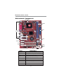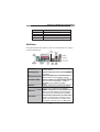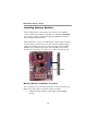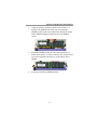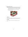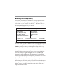
1
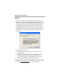
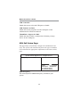
Motherboard User’s Guide This publication, including photographs, illustrations and software, is under the protection of international copyright laws, with all rights reserved. Neither this manual, nor any of the material contained herein, may be reproduced without the express written consent of the manufacturer. The information in this document is subject to change without notice. The manufacturer makes no representations or warranties with respect to the contents hereof and specifically disclaims any implied warranties of merchantability or fitness for any particular purpose. Further, the manufacturer reserves the right to revise this publication and to make changes from time to time in the content hereof without obligation of the manufacturer to notify any person of such revision or changes. Trademarks IBM, VGA, and PS/2 are registered trademarks of International Business Machines. VIA is a registered trademark of VIA Technologies, Inc. Microsoft, MS-DOS and Windows 98/ME/NT/2000/XP are registered trademarks of Microsoft Corporation. AMI is a registered trademark of American Megatrends Inc. Other names used in this publication may be trademarks and are acknowledged. Copyright © 2004 All Rights Reserved M789CG Series, V3.0B CLE266/November 2004 i Motherboard User’s Guide Table of Contents Trademark ................................................................................... I Static Electricity Precautions ............................................................ III Pre-Installation Inspection ................................................................ III Features & Checklist Translations ........................................ V Chapter 1: Introduction ............................................................ 1 Key Features ........................................................................................ 2 Package Contents ................................................................................ 5 Chapter 2: Motherboard Installation ..................................... 6 Motherboard Components ................................................................... 7 I/O Ports ............................................................................................... 8 Installing Memory Modules ................................................................. 9 Jumper Settings .................................................................................. 11 Install the Motherboard ..................................................................... 12 Connecting Optional Devices ............................................................ 13 Install Other Devices .......................................................................... 16 Expansion Slots .................................................................................. 18 Chapter 3: BIOS Setup Utility ............................................... 20 Introduction ....................................................................................... 20 Running the Setup Utility ........................... …………………………...21 Standard CMOS Setup Page ............................................................. 22 Advanced Setup Page ........................................................................ 23 Power Management Setup Page ........................................................ 26 PCI/Plug and Play Setup Page .......................................................... 28 Load Optimal Settings ....................................................................... 29 Load Best Performance Settings ........................................................ 29 Features Setup Page .......................................................................... 29 CPU PnP Setup Page ......................................................................... 31 Hardware Monitor Page .................................................................... 32 Change Password .............................................................................. 33 Exit ..................................................................................................... 33 Chapter 4: Software & Applications ..................................... 34 Introduction ....................................................................................... 34 Installing Support Software ............................................................... 35 Bundled Software Installation ........................................................... 37 ii Motherboard User’s Guide Static Electricity Precautions Static electricity could damage components on this motherboard. Take the following precautions while unpacking this motherboard and installing it in a system. 1. Don’t take this motherboard and components out of their original static-proof package until you are ready to install them. 2. While installing, please wear a grounded wrist strap if possible. If you don’t have a wrist strap, discharge static electricity by touching the bare metal of the system chassis. 3. Carefully hold this motherboard by its edges. Do not touch those components unless it is absolutely necessary. Put this motherboard on the top of static-protection package with component side facing up while installing. Pre-Installation Inspection 1. Inspect this motherboard whether there are any damages to components and connectors on the board. 2. If you suspect this motherboard has been damaged, do not connect power to the system. Contact your motherboard vendor about those damages. iii Motherboard User’s Guide Notice: 1. Owing to Microsoft’s certifying schedule is various to every supplier, we might have some drivers not certified yet by Microsoft. Therefore, it might happen under Windows XP that a dialogue box (shown as below) pop out warning you this software has not passed Windows Logo testing to verify its compatibility with Windows XP. Please rest assured that our RD department has already tested and verified these drivers. Just click the “Continue Anyway” button and go ahead the installation. 2. USB 2.0 Driver Limitations: 2-1 The USB 2.0 driver only supports Windows XP and Windows 2000. 2-2 If you connect a USB 2.0 hub to the root hub, plugging USB devices into this hub, the system might not successfully execute certain USB devices’ connection because it could not recognize these devices. Currently, we are working on such limitations’ solution. As soon as the solution is done, the updated USB drive will be released to our website: www.pcchips.com for your downloading. iv Motherboard User’s Guide Traduction des Caractéristiques & Liste de contrôle Liste de contrôle Le coffret de votre carte mère contient les éléments suivants: • La carte mère • Le Manuel utilisateur • Un câble plat pour lecteur de disquette (optionnel) • Une câble plat pour lecteur IDE • CD de support de logiciels Caractéristiques Type de CPU • Prend en charge le CPU VIA C3 interne • Supporte le Bus Frontal de 133 MHz Chipset Ce chipset comporte VIA CLE266 Northbridge et 8235 Southbridge conformément à une architecture novatrice et dimensionnable avec une fiabilité et des performances prouvées. Voici une liste de l’organisation des chipset et de leurs caractéristiques respectives : • Interface de CPU de Hautes Performances: Prend en charge les processeurs VIA C3; CPU à Bus Frontal (FSB) de 133/100/66 MHz • Le contrôleur d’Hôte 8 bits V-Link à Bande passante élevée de 266Mo/sec supporte une interface d'Hôte V-Link 66 MHz avec une bande passante totale de 266 Mo/sec • Le Contrôleur DRAM DDR/SDR de hautes performances supporte l’interface DRAM synchrone avec CPU hôte (133/100 MHz) pour la configuration la plus flexible; Prend en charge 4 banques jusqu'à des DRAM de 2 Go • Accélérateur Graphique / Vidéo intégré: Tampon de trame de 16/32/64 Mo utilisant la mémoire système; Performance AGP 4x Interne • Contrôleur de Bus PCI concurrent: Interface PCI 3.3V 32 bits Conforme PCI 2.2, fonctionnant en 33 MHz avec entrées à tolérance de 5V. • Contrôleur Fast Ethernet: Fonctionnement full et half duplex en 1/10/100 MHz • Contrôleur EIDE de mode maître UltraDMA-133/100/66/33 : Vitesse de transfert jusqu’à 133Mo/sec pour couvrir les lecteurs PIO mode 4, multi-mots DMA mode 2, et interface UltraDMA-133 • Contrôleur Audio Numérique Direct Sound Ready AC’97: Conforme AC’97 2.1 • Contrôleur de bus USB: Compatible USB v2.0 et Interface de Contrôleur d’Hôte Avancé (EHCI) v1.0; compatible USB v1.1 et Interface de Contrôleur d’Hôte Universel (UHCI) v1.1 Support de Mémoire • Deux logements DIMM pour modules mémoire DDR • Prend en charge le bus mémoire DDR266/200 • La mémoire maximum installée est 2Go Logements d’Extension • Un logement CNR • Deux logements PCI 32 bits pour interface de bus conforme PCI 2.2 v Motherboard User’s Guide Canaux IDE internes • Deux Connecteurs IDE • Prend en Charge les modes PIO (Entrée/Sortie Programmable) et DMA (Accès Direct à la Mémoire) • Supporte maîtrise de bus Ultra DMA IDE avec vitesse de transfert de 133/100/ 66/33 Mo/sec VGA Interne • L’Accélérateur Graphique/Vidéo intégré prend en charge l’Architecture de Mémoire Partagée (SMA) optimisée • Chemins de données 128 bits séparés entre North Bridge et noyau graphique pour flux de données de pixels et accès de texture/commande • Moteur graphique avec horloge allant jusqu’à 133 MHz découplé de l’horloge mémoire • Lecture vidéo DVD de haute qualité AC’97 Codec • 6 canaux et conforme aux Spéc. Intel AC’97 (REV. 2.3), respectant les exigences de MicrosoftPC2001 • Gestion d’alimentation avancée et capacités d’économie d’énergie. • Fonction de ligne d’entrée stéréo partagée avec la sortie Contour. • Entrée de CD Audio analogique pseudo différentielle de haute qualité. • Support d’Entrée S/PDIF : Sortie 96/ 48 kHz avec 24/ 20/ 16 bits • Technologie logicielle complémentaire de valeur. Supporte la plupart des standards de l’industrie de son 3D PC et support de fonction de karaoké unique qui comprend l’écho microphone, décalage de touche, et annulation vocale. Ports E/S Internes La carte mère possède un jeu complet de ports d’E/S et de connecteurs: • Deux ports PS/2 pour souris et clavier • Un port série • Un port parallèle • Un port VGA • Un port LAN (optionnel) • Quatre ports USB 2.0 de panneau arrière • Prises audio pour microphone, ligne d’entrée et ligne de sortie LAN Ethernet intégré (optionnel) • Solution de Couche Physique 10Base-TX/100Base-TX • Double Vitesse – 100/10 Mbps • Interface MII vers Contrôleur Ethernet/Configuration & Etat • Négociation automatique : 10/100, Full/Half Duplex • Conforme à tous les Standards IEEE802.3, 10Base-T et 100Base-TX Applicables USB 2.0 • Conforme aux Spécifications de Bus Série Universel Révision 2.0 • Conforme aux Spécifications d’interface de Contrôleur d’Hôte Amélioré de Intel Révision 1.0 • Conforme aux Spécifications d’Interface de Contrôleur d’Hôte Universel Révision 1.1 • Le périphérique multifonction PCI consiste en deux noyaux de Contrôleur vi Motherboard User’s Guide d’Hôtes UHCI pour signalisation pleine/faible vitesse et un noyau de Contrôleur d’Hôtes EHCI pour signalisation haute vitesse • Le hub racine consiste en 4 ports de face en aval avec émetteurs-récepteurs de couche physique intégrés partagés par le Contrôleur d’Hôte UHCI et EHCI • Support des Spécifications d’Interface de Gestion d’Alimentation de Bus PCI version 1.1 • Support hérité pour tous les ports face à l’aval. Remarque: Certaines spécifications matérielles et éléments de logiciels peuvent être modifiés sans avertissement. vii Motherboard User’s Guide Checkliste Funktionen & Checkliste Die Verpackung Ihres Motherboards enthält folgende Teile: • Motherboard • Handbuch • Bandkabel für Floppylaufwerke (optional) • Bandkabel für IDE-Laufwerke • Software -CD Ausstattung CPU-Typ • Unterstützt Onboard-VIA C3 CPU • Unterstützt 133 MHz Front-Side Bus Chipsatz Dieser Chipsatz besteht aus einer VIA CLE266 Northbridge und einer 8235 Southbridge. Die Chipsatzarchitektur ist in einem innovativen und skalierbaren Design gehalten und verspricht sowohl Zuverlässigkeit als auch Leistungsstärke. Unten stehend finden Sie eine Liste mit den Chipsatzteilen und deren jeweiligen Funktionen: • Hochleistungs CPU-Schnittstelle: Unterstützt VIA C3-Prozessoren; 133/100/66 MHz CPU Front Side Bus (FSB) • 8-Bit-Link Host Controller mit einer Bandbreite von 266MB/Sek unterstützt die 66MHz V-Link Host-Schnittstelle mit der totalen Bandbreite von 266MB/Sek. • Fortgeschrittener Hochleistungs-DDR/SDR DRAM Controller unterstützt gleichzeitige DRAM-Schnittstelle mit Host-CPU (133/100 MHz) für beste flexible Einstellung; Unterstützt 4 Speicherbänke für bis zu 2 GB DRAM • Integrierte Grafikfunktion / Videobeschleuniger : 16/32/64 Framebuffer verwendet Systemspeicher; interne AGP 4x-Funktionalität. • Mitwirkender PCI-Bus-Controller: 33 MHz-Betrieb, nach den Richtlinien von PCI 2.2, 32 Bit 3.3V PCI-Schnittstelle mit einer Eingangsenergie-Toleranz von 5V. • Fast Ethernet Controller: Voller und halber Duplex-Betrieb von 1/10/100 MHz • UltraDMA-133/100/66/33 Master-Modus EIDE-Controller: Übertragungsrate von bis zu 133MB/Sek um die Driver des PIO-Modus 4, Multi-Word-DMA-Modus 2, und eine UltraDMA-133-Schnittstelle zu decken. • Direct Sound Ready (Direkter Fertigton) AC’97 Digital Audio Controller: nach den Richtlinien von AC’97 2.1 • Universaler Serien-Bus-Controller: USB v2.0 und vergrösserte Host-Controller-Schnittstelle (EHCI) kompatibel mit v1.0; USB v1.1 und Universale HostController-Schnittstelle (UHCI) kompatibel mit v1.1 Speicherunterstützung • Zwei DIMM Steckplätze für DDR Speichermodule • Unterstützt DDR266/200 Speicherbus • Maximal auf 2GB Speicher erweiterbar Erweiterungssteckplätze • Ein CNR-Steckplatz • Zwei 32-Bit PCI-Steckplätze für PCI 2.2-kompatibles Businterface viii Motherboard User’s Guide Onboard IDE-Kanäle • Zwei IDE-Header • Unterstützt die Modi PIO (Programmable Input/Output) und DMA (Direct Memory Access) • Unterstützung für IDE Ultra DMA-Busmastering mit Transferraten von 133/ 100/66/33 MB/Sek Onboard- VGA • Integrierte Grafikfunktion/Videobeschleuniger unterstützt optimierte “Shared Memory Architecture” (SMA) • Separate 128-Bit-Datenpfade zwischen der Northbridge und dem Grafikkern für Pixel-Datenfluss und extur/Befehlszugriff • Grafik-Engine auf bis zu 133MHz taktbar; vom Speichertakt entkoppelt • Qualitativ hochwertige DVD-Video-Wiedergabe AC’97 Codec • 6 Kanäle und in Übereinstimmung mit den Spezif. von Intel AC’97 (REV. 2.3), gemäß den Richtlinien von MicrosoftPC2001 • Fortgeschrittener Stromzuführungsbetrieb und Stromsparfähigkeiten. • Stereo „Line-in-Funktion“ geteilt mit „Surround out“. • Hochqualitäts pseudo-unterschiedlicher Analog-CD-Audio-Eingang. • S/PDIF Input-Unterstützung: Output 96 / 48 kHz mit 24 / 20 / 16 Bits • Wertvolle zusätzliche Software-Technologie: Unterstützt die meisten Industrienormen des PC-3D-Tons und die einzigartige Karaoke-Funktion kennzeichnet sich durch das Mikrofonecho, dem Tastenwechsel und der Stimmunterbrechung. Onboard-I/O-Ports Das Motherboard verfügt über einen kompletten Satz von I/O-Schnittstellen und Anschlüssen: • Zwei PS/2-Steckplätze für Maus und Tastatur • Ein serieller Steckplatz • Ein paralleler Steckplatz • Ein VGA Steckplatz • Ein LAN Steckplatz (optional) • Four back-panel USB2.0 ports • Audioanschlüsse für Mikrofon, line-in und line-out IIntegriertes Ethernet LAN (optional) • 10Base-T/100Base-TX Physical Layer Solution • Dual-Geschwindigkeit – 100/10 MB/Sek. • MII Interface zu Ethernet Controller/Konfiguration & Status • Autom. Verhandlung: 10/100, Voll/Halbduplex • Entspricht allen IEEE802.3, 10Base-T und 100Base-TX Standards USB 2.0 • Entspricht Universal Serial Bus-Spezifikation, Revision 2.0 • Entspricht Intels Enhanced Host Controller Interface-Spezifikation, Revision 1.0 • Entspricht Universal Host Controller Interface -Spezifikation Revision 1.1 • PCI-Multifunktionsgerät besteht aus zwei UHCI Host Controller-Kernen für Signalübertragung bei voller und niedriger Geschwind- ix Motherboard User’s Guide igkeit sowie einem EHCI Host Controller-Kern für Hochgeschwindigkeits- Signalübertragung • Root Hub besteht aus 4 Downstream-Ports mit integrierten Physical LayerÜberträgern für gemeinsame Nutzung durch UHCI und EHCI Host Controller • Unterstützt PCI-Bus Power Management Interface , Spezifikation Release 1.1 • Legacy-Unterstützung für alle Downstream-Ports Hinwei: Bestimmte Hardwarespezifikationen und Teile der softwareausstattung können ohne weitere Ankündigung abgeändert werden.without prior notice. x Motherboard User’s Guide Lista Traduzione Funzioni e Lista L’imballo della scheda madre é composto da: • La scheda madre • Il manuale • Una piattina per il collegamento dei drive (opzionale) • Una piattina IDE • Il CD con il Software di supporto Caratteristiche Tipo CPU • Supporta la CPU VIA C3 installata • Supporta Front Side Bus (FSB) di 133 MHz Chipset In accordo ad una archittettura scabile e innovative sono presenti nel chipset il Northbridge VIA CLE266 e Southbridge 8235. Segue una lista con i chipset e le rispettive funzioni: • Interfaccia CPU di elevata performance: Supporta processori VIA C3 e CPU FSB (Front Side Bus) di133/100/66 MHz • Controller Host Link 8bit ad alta velocità (266MB) in grado di supportare interfacce Link Host a 66 MHz • Controller DRAM DDR/SDR ad alte prestazioni in grado di supportare le DRAM sincrone con CPU host (133/100 MHz) per una maggiore flessibilità nella configurazione; Supporta 4 banchi sino a 2GB di DRAM • Grafica integrata/acceleratore video: buffer di frame da 16/32/64 che sfrutta la memoria di sistema; prestazione Internal AGP 4x • Programma di controllo PCI Bus: operatività 33 MHz , compatibile PCI 2.2, interfaccia 32 bit 3.3V PCI con immissione dati tollerante V5 • Programma di controllo veloce Ethernet: 1/10/100 MHz operatività piena o mezzo duplex • Programma EIDE di controllo UltraDMA-133/100/66/33 Master Mode EIDE: Velocità di trasferimento fino a 133MB/sec che copre PIO mode 4, drive multiparola modalità DMA e interfaccia UltraDMA-133 • Programma di controllo audio digitale per suono diretto AC’97: AC’97 2.1 compatibile • Programma di controllo per Bus universali seriali: USB v2.0 ed interfaccia Host Controller migliorata (EHCI) v1.0 compatibile; USB v1.1 e interfaccia universale Host Controller (UHCI) v1.1 compatibile Supporto Memoria • • • Due slot DIMM per moduli di memoria DDR Supporta bus di memoria DDR266/200 Quantità massima di memoria installabile, 2GB Slot di espansione • Una slot CNR • Due slot PCI a 32 bit per interfaccia bus PCI 2.2 xi Motherboard User’s Guide Canali IDE Integrati • Due connettori IDE • Supporto della modalità PIO (Programmable Input/Output) e DMA (Direct Memory Access) • Supporto per le modalità Bus Mastering e Ultra DMA ATA 133/100/66/33 VGA Integrato • Grafica integrata/acceleratore video supportano SMA (Shared Memory Architecture) ottimizzata • Separa i percorsi dati da 128 bit tra north bridge e graphic core per flusso di dati pixel e trama/accesso comandi • Orologio Graphics engine sino a 133MHz separato dalla memoria dell’orologio. • Riproduttore DVD video di alta qualità AC’97 Codec • 6 canali conforme alle specifiche dello standard IntelAC’97 (REV. 2.3), rispettando inoltre i requisiti MicrosoftPC2001 • Supporto delle funzionalità relative alla Gestione avanzata del Risparmio Energia. • Funzione Stereo Line-in condivisa con l’uscita Surround out. • Input pseudo analogico CD Audio ad alta qualità. • Supporto Input S/PDIF, Output da 96/48 kHz con 24/20/16 bit • Tecnologie aggiuntive di grande valore: Supporto garantito dei maggiori standard industriali relative al sonoro PC 3D, incredibile funzione karaoke con supporto dell’eco sull’ingresso microfono, key shifting e cancellazione della voce. Porte I/O integrate La scheda madre è dotata da una serie completa di porte e connettori I/O: • Due porte PS/2 per tastiera e mouse • Una porta seriale • Una porta parallela • Una porta VGA • Una porta LAN (opzionale) • Quattro porte USB 2.0 sul retro del pannello • Jack audio per microfono, ingresso linea e uscita linea Fast Ethernet LAN (opzionale) • Soluzione 10Base-T/100Base-TX a livelli fisici • Doppia velocità – 100/10 Mbps • Controller Interfaccia MII a Ethernet/Configurazione e stato • Auto-negoziazione: 10/100, Full/Half Duplex • Conforme a tutte le norme IEEE802.3, 10Base-T e 100Base-TX USB 2.0 • Conforme alle specifiche Universal Serial Bus 2.0 • Conforme alle specifiche Intel Enhanced Host Controller revisione 1.0 • Conforme alle specifiche Universal Host Controller Interface revisione 1.1 • Il dispositivo PCI multifunzione consiste di due schede di controllo UHCI per lat rasmissione segnali pieno/basso e una scheda di controllo EHCI per la trasmissione segnali ad alta velocità. xii Motherboard User’s Guide • Il porto hub di base consiste di 4 porte downstream con ricetrasmittenti integrati nel layer fisico condivisi dalla scheda di controllo interfaccia UHCI e EHCI • Support PCI-Bus Power Management Interface Specification release 1.1 • Supporto per interfaccia risparmio energia bus PCI specifiche release 1.1 • Supporto per tutte le porte downstream precedenti Nota: Alcune specifiche hardware ed elementi software sono soggetti a variazioni senza preavviso. xiii Motherboard User’s Guide Traducción de Características & Lista LISTA DE VERIFICACIÓN El paquete de su placa principal contiene los sigtes. ítems: • La placa principal • El Manual del Usuario • Un cable cinta para el lector de disquete (optativo) • Un cable cinta para el lector IDE • CD de Software de soporte Características Tipo de CPU • Soporta la CPU VIA C3 CPU abordo • Soporta el Bus de Lado Frontal 133 MHz Chipset Hay VIA CLE266 Northbridge y 8235 Southbridge en este chipset en confomidad con una arquitectura innovadora y escalable con fiabilidad y rendimiento comprobados. He aquí una lista del arreglo del chipset y sus respectivas características: • Interfaz de CPU de alto rendimiento: Soporte para los procesadores de VIA C3; Bus de Lado Frontal (FSB) de CPU en 133/100/66 MHz • Controlador Anfitrión V-Link de 8-bit de ancho de banda de 266MB/seg soporta la interfaz de Anfitrión V-Link de 66MHz con el ancho de banda total de 266MB/seg • Controlador DDR/SDR DRAM de alto rendimiento avanzado soporta la interfaz DRAM sincrónica con CPU anfitriona (133/100 MHz) para la configuración más flexible; Soporta 4 bancos hasta DRAMs de 2 GB • Acelerador de Gráficas/Vídeo Integrado : buffer de marco 16/32/64 que usa la memoria de sistema; rendimiento de AGP 4x interno • Controlador de Bus PCI concurrente: operación de 33 MHz, conformidad PCI 2.2, interfaz 32 bit 3.3V PCI con entradas tolerantes de 5V • Controlador Fast Ethernet: operación duplex completo y medio de 1/10/100 MHz • Controlador EIDE de Modo Máster UltraDMA-133/100/66/33: Índice de transferencia hasta 133MB/seg para cubrir el PIO modo 4, unidades de multiword DMA modo 2, e interfaz UltraDMA-133 • Sonido Directo Listo Controlador de Sonido Digital AC’97: Conformidad AC’97 2.1 • Controlador de Bus Serial Universal: USB v2.0 y compatible con la Interfaz de Controlador Anfitrión Reforzado (EHCI) v1.0; USB v1.1 y compatible con la Interfaz de Controlador Anfitrión Universal (UHCI) v1.1 Soporte de Memoria • Dos ranuras DIMM para módulos de memoria DDR • Soporta bus de memoria en DDR266/200 • Memoria máxima instalada es 2GB Ranuras de Expansión • Una ranura CNR • Dos ranuras 32-bit PCI para la interfaz de bus conforme con PCI 2.2 xiv Motherboard User’s Guide Canales IDE abordo • Dos conectores IDE • Soporta modos PIO (Entrada/Salida Programable/Programmable Input/ Output) y modos DMA (Acceso de Memoria Directo/Direct Memory Access). • Soporta mastering de bus IDE Ultra DMA con índices de transferencia de 133/100/66/33 MB/seg VGA abordo • El acelerador de Gráficas/Vídeo integrado soporta la Arquitectura de Memoria Compartida (SMA) optimizada • Rutas de datos de 128-bit separadas entre el north bridge y el centro de gráficas para el flujo de datos de pixel y acceso de textura/comando • Relojes de motro de gráficas hasta 133MHz separados del reloj de memoria • Reproducción de vídeo DVD de alta calidad AC’97 Codec • 6 canales y conformidad de la Espec. IntelAC’97 (REV. 2.3), satisface los requisitos de MicrosoftPC2001 • Administración de suministro avanzada y capacidades de ahorro de energía. • La función Stereo Line-in compartida con Surround out. • Entrada de Audio CD analógica seudodiferencial de alta calidad. • Soporte de Entrada S/PDIF: Salida de 96 / 48 kHz con 24 / 20 / 16 bits • Valiosa tecnología de software adicional: Soporta la mayoría de las normas industriales del sonido PC 3D y la función Karaoke se caracteriza por el eco de micrófono, cambio a teclas y cancelación vocal Puertos I/O Abordos La placa principal tiene un juego completo de puertos I/O y conectores: • Dos puertos PS/2 para ratón y teclado • Un puerto serial • Un puerto paralelo • Un puerto VGA • Un puerto LAN (optativo) • Cuatro puertos USB2.0 del panel trasero • Clavijas de sonido para micrófono, entrada y salida de línea Fast Ethernet LAN (optativo) • Solución de Capa Física 10Base-T/100Base-TX • Velocidad Dual – 100/10 Mbps • Interfaz MII al Controlador Ethernet/Configuración & Estado • AutoNegociación: 10/100, Duplex Completo/Medio • Satisface todas las normas aplicables de IEEE802.3, 10Base-T y 100Base-TX USB 2.0 • Conforme con la Especificación de Bus Serial Universal Revisión 2.0 • Conforme con Controlador Anfitrión Reforzado de Intel Interface Specification Revision 1.0 • Conforme con la Especificación de Interfaz de Controlador Anfitrión Universal Revisión 1.1 • Dispositivo PCI multi-función se consiste de dos centros de Controlador Anfitrión UHCI para señalización de velocidad completa/baja y un centro de Controlador Anfitrión EHCI para señalización de alta velocidaa xv Motherboard User’s Guide • Root hub consiste de 4 puertos que miran hacia abajo con transceptores de capa física integrado compartido por Controlador Anfitrión UHCI y EHCI transceivers shared by UHCI and EHCI Host Controller • Soporta Especificación de Interfaz de Administración de Energía de BUS PCI versión 1.1 • Soporte de legado para todos los puetos que miran hacia abajo Nota: Algunas especificaciones de hardware e ítems de software son sujetos a cambio sin aviso previo . xvi Motherboard User’s Guide Tradução da Lista & Características Lista de verificação A embalagem da sua placa principal contém os seguintes itens: • A placa principal • O Manual do Utilizador • Um cabo para a unidade de disquetes (opcional) • Um cabo para a unidade IDE • CD de suporte para o software Características Tipo CPU • Suporta CPU VIA C3 integrada • Suporta Barramento Frontal/Lateral 133 MHz Chipset Conta com VIA CLE266 Northbridge e 8235 Southbridge neste chipset, de acordo com uma arquitectura inovadora e escalável com um nível de confiança e desempenho comprovado. Aqui fica uma lista da organização do chipset e das respectivas características. • Interface CPU de Alta Performance: Suporte para processadores VIA C3; Barramento Frontal Lateral (FSB) CPU de 133/100/66 MHz • Banda larga de 266MB/seg 8-bit-Link Host Controller suporta 66MHz V-Link Host interface com banda larga com capacidade de 266MB/seg • Alta performance avançada DDR/SDR DRAM Controller suporta DRAM interface síncrono com host CPU (133/100 MHz) para uma configuração mais flexível; Suporta 4 bancos de dados de até 2 GB DRAMs • Integrated Graphics / Video Accelerator : 16/32/64 frame buffer using system memory; Internal AGP 4x performance • Controlador Corrente PCI do Bus: funcionamento 33 MHz, compatível com PCI 2.2, interface 32 bit 3.3V PCI com entradas tolerantes 5V • Controlador Ethernet Rápida: 1/10/100 MHz funcionamento completo e semi-duplex • Controlador UltraDMA-133/100/66/33 Master Mode EIDE: Taxa de transferência até 133MB/sec para abranger os drivers PIO mode 4, multi-word DMA mode 2, e o interface UntraDMA-133 • Controlador Direct Sound Preparado para AC’97 Áudio Digital: compatível com AC’97 2.1 • Controlador Universal de Série do Bus: USB v2.0 e (EHCI) Interface Melhorado do Controlador Central compatível com v1.0; (UHCI) Interface USB v1.1 e Universal do Controlador Central compatível com v1.1 Suporte de memória • Dois sockets DIMM para módulos de memória DDR • Suporta barramento de memória DDR266/200 • A memória máxima instalada é de 2GB Slots de expansão • Um slot CNR • Duas slots PCI de 32 bit para interface bus compatível com PCI 2.2 xvii Motherboard User’s Guide Canais IDE na placa • Dois conectores IDE • Suporta modos PIO (Input/Output Programável) e DMA (Direct Memory Access) • Suporta IDE Ultra DMA bus mastering com razão de transferência de 133/ 100/66/33 MB/seg VGA Integrado • Acelerador Gráfico / Vídeo suporta Arquitectura de Memória Compartida (SMA) optimizada • Caminhos de dados de 128-bit separados entre a ponte norte e o núcleo gráfico para fluxo de dados pixel e acesso textura/comando • Relógios do motor gráfico de até 133MHz desacoplado do relógio de memória • Alta qualidade de reprodução de vídeo DVD AC’97 Codec • Spec de 6 canais e de acordo com a norma IntelAC’97 (REV. 2.3) Spec, de acordo com os requisitos MicrosoftPC2001 • Capacidades de gestão avançada da corrente e de poupança de energia. • Função da entrada de stereo partilhada com a saída do som Surround. • Entrada de áudio analógica com pseudo-diferencial para CD de alta qualidade. • Suporte da entrada S/PDIF: Saída de 96 / 48 kHz com 24 / 20 / 16 bits • Tecnologia de software de actualização valiosa: Suporta a maior parte dos padrões da indústria de som 3D para PC e possui um suporte único para a função de karaoke que possui um eco do microfone, mudança de teclas, e cancelamento vocal. Portas I/O na placa A placa principal possui um conjunto completo de portas e conectores I/O: • Duas portas PS/2 para o rato e teclado • Uma porta série • Uma porta paralela • Uma porta VGA • Uma porta LAN (opcional) • Quatro portas USB2.0 instaladas no painel traseiro • Jacks audio para microfone, line-in e line-out Ethernet LAN Integrada (opcional) • Solução Camada Física 10Base-T/100Base-TX • Velocidade Dupla – 100/10 Mbps • Interface MII com Controlador/Configuração Ethernet & Estado • Auto Negociação: 10/100, transmissão em Full/Half Duplex • Cumpre com todas as normas aplicáveis: IEEE802.3, 10Base-T e 100BaseTX USB 2.0 • Compatível com Universal Serial Bus Revisão 2.0 da especificação • Compatível com controlador Enhanced Host da Intel Revisão 1.0 da especificação da interface • Compatível com controlador Universal Host Revisão 1.1 da especificação da Interface • O dispositivo PCI muli-funções consiste em dois núcleos de Controlador UHCI xviii Motherboard User’s Guide Host Controller para sinalização de velocidade total/baixa em um núcleo de Controlador EHCI Host para sinalização de alta velocidade • O núcleo de raiz consiste em 4 portas de protecção a jusante com transreceptores de camadas físicas integrados partilhados pelos controladores Host UHCI e EHCI • Suporte de gestão de energia PCI-Bus Revisão 1.1 da especificação da interface • Suporte para todas as portas de protecção a jusante transceivers Nota: As especificações de alguns artigos de hardware e software encontram-se sujeitos a alterações sem aviso prévio. xix Motherboard User’s Guide 功能和检查单翻译 检查单 您的主板包装含有以下项目: • 主板 • 用户手册 • 一根磁盘驱动器扁平电缆(可选) • 一根 IDE 驱动器扁平电缆 • 软件支持 CD 功能 CPU 类型 • 支持集成 VIA C3 CPU • 支持 133 MHz 前端总线 芯片组 芯片组包含 VIA CLE266 北桥和 8235 南桥,它基于一种新型的、可扩展的架构, 能提供已经证明的可靠性和高性能。 • 高性能 CPU 接口: 支持 VIA C3 处理器;133/100/66 MHz CPU 前端总线 (FSB) • 高带宽 266MB/sec 8-bit-Link 主控器,支持 66MHz V-Link 主控接口,总带宽 可达 266MB/sec • 增强高性能 DDR/SDR DRAM 控制器,支持与主 CPU (133/100 MHz) 的 DRAM 接口同步用于灵活配置; 4 个内存插槽,最大可支持 2 GB DRAM • 集成图形/视频加速器:16/32 使用系统内存的帧缓冲;内部 AGP 4x 性能 • 并发 PCI 总线控制器:工作频率 33 MHz,符合 PCI2.2 标准,带 5V 输入的 32 位 3.3V PCI 接口。 • 快速以太网控制器:1/10/100 MHz 全双工和半双工操作 • UltraDMA-133/100/66/33 主控模式 EIDE 控制器:传输速率可达 133MB/sec, 支持 PIO 模式 4、多字 DMA 模式 2 驱动程序和 UltraDMA-133 接口 • AC’97 数字音频控制器:符合 AC’97 2.1 标准 • 通用串行总线控制器:兼容 USB v2.0 和增强主控器接口 (EHCI) v1.0;兼容 USB v1.1 和通用主控器接口 (UHCI) v1.1 内存支持 • 2 个用于 DDR 内存条的 DIMM 插槽 • 支持 DDR266/200 存储总线 • 内存最多可达 2GB 扩展槽 • 1 个 CNR 插槽 • 2 个 32 位 PCI 插槽,用于 PCI 2.2 兼容总线接口 xx Motherboard User’s Guide Onboard IDE 通道 • 2 个 IDE 接口 • 支持 PIO (程控输入/输出) 和 DMA (直接存储器存取) 模式 • 支持 IDE Ultra DMA 总线控制,传输速率可达 133/100/66/33 MB/sec 集成 VGA • 集成图形/视频加速器,支持优化共享内存架构 (SMA) • 北桥和图形核心间的独立 128 位数据路径,用于像素数据流和纹理/指令访问 • 由存储器时钟分离出的、最高 133 MHz 的图形引擎时钟 • 高质量 DVD 视频播放 AC’97 编解码器 • • • • • • 6 声道,符合 Intel AC’97 (REV. 2.3) 规格,符合 Microsoft PC2001 标准 高级电源管理和节电功能。 共享环绕输出的立体声线入功能。 高质量伪差分模拟 CD 音频输入。 支持 S/PDIF 输入:输出 96 / 48 kHz,24 / 20 / 16 位。 增值软件技术:支持大部分 PC 3D 立体声行业标准和卡拉 OK 功能,支持话 筒回声消除、键移动和声音消除功能。 集成 I/O 端口 此主板具有完整的 I/O 端口和插孔: • 2 个用于连接鼠标和键盘的 PS/2端口 • 1 个串口 • 1 个并口 • 1 个 VGA 端口 • 1 个 LAN 端口 (可选) • 4 个后面板 USB2.0 端口 • 麦克风、线入和线出声音插孔 快速以太网 LAN (可选) • 10Base-T/100Base-TX 物理层解决方案 • 双速 -100/10 Mbps • 到以太网控制器/配置 & 状态的 MII 接口 • 自动协商:10/100,全双工/半双工 • 符合所有相应的 IEEE 802.3、10Base-T 和 100Base-Tx 标准 USB2.0 • 符合通用串行总线规格 2.0 版本 • • • • • • 符合 Intel 1.0 版本的增强主控器接口规格 符合 1.1 版本的通用主控器接口规格 PCI 多功能设备由 2 个用于全速/低速传输数据的 UHCI 主控器和 1 个用于高 速传输数据的 EHCI 主控器组成 Root 集线器包括 4 个下行端口,带有与 UHCI 和 EHCI 主控制器共用的集成 物理层收发器。 支持 1.1 版本的 PCI 总线电源管理接口规格 支持所有传统下行端口 说明 : 某些硬件规格和软件项目若有更改恕不另行通知。 xxi Motherboard User’s Guide xxii Motherboard User’s Guide Chapter 1 Introduction This motherboard has a VIA C3 CPU onboard with front-side bus speed up to 133MHz. This motherboard integrates the VIA CLE266 Northbridge and 8235 Southbridge chipsets that support DDR 266MHz, Ultra DMA 33/66/100/133 function and remarkably high system performance under all types of system operations It supports built-in USB 2.0 providing higher bandwidth. It implements Universal Serial Bus Specification Revision 2.0 and is compliant with UHCI 1.1 and EHCI 1.0. The motherboard supports the built-in AC’97 Codec, two 32-bit PCI slots, one CNR (Communications and Networking Riser) slot, and an onboard 10BaseT/100BaseTX Network interface (optional). This motherboard integrates a 128-bit 3D/2D graphics engine and a high-performance 3D accelerator. In addition, this motherboard has a full set of I/O ports including two PS/2 ports for mouse and keyboard, one serial port, one VGA port, one parallel port. one LAN port (optional), audio jacks for microphone, line-in and line-out, four back-panel USB2.0 ports and onboard USB header USB1 providing two extra ports by connecting the extended USB module to the motherboard. This motherboard has all the features you need to develop a powerful multimedia workstation. The board is FLEX ATX size and has a power connector for an ATX power supply. 1 Motherboard User’s Guide Key Features The key features of this motherboard include: CPU Type • Supports the VIA C3 CPU onboard • Supports 133 MHz Front-Side Bus Chipset There are VIA CLE266 Northbridge and 8235 Southbridge in this chipset in accordance with an innovative and scalable architecture with proven reliability and performance. A few of the chipset’s advanced features are: • High Performance CPU Interface: Support for VIA C3 processors; 133/100/66 MHz CPU Front Side Bus (FSB) • High Bandwith 266 MB/sec 8-Bit V-Link Host Controller: Supports 66 MHz V-Link Host Interface with total bandwidth of 266 MB/sec • Advanced High-Performance DDR/SDR DRAM Controller: DRAM interface synchronous with host CPU (133/100 MHz) for most flexible configuration; Supports 4 banks up to 2 GB DRAMs • Integrated Graphics / Video Accelerator : 16/32/64 frame buffer using system memory; Internal AGP 4x performance • Concurrent PCI Bus Controller: 33 MHz operation, PCI 2.2 compliant, 32 bit 3.3V PCI interface with 5V tolerant inputs • Fast Ethernet Controller: 1/10/100 MHz full and half duplex operation • UltraDMA-133/100/66/33 Master Mode EIDE Controller: Transfer rate up to 133MB/sec to cover PIO mode 4, multiword DMA mode 2 drives, and UltraDMA-133 interface • Direct Sound Ready AC’97 Digital Audio Controller: AC’97 2.1 compliant 2 Chapter 1: Introduction • Universal Serial Bus Controller: USB v2.0 and Enhanced Host Controller Interface (EHCI) v1.0 compatible; USB v1.1 and Universal Host Controller Interface (UHCI) v1.1 compatible Memory Support • Two 184-pin DIMM sockets for DDR memory modules • Supports DDR266/200 memory bus • Maximum installed memory is 2GB Expansion Slots • One CNR slot • Two 32-bit PCI slots for PCI 2.2-compliant bus interface Onboard IDE channels • Two IDE Connectors • Supports PIO (Programmable Input/Output) and DMA (Direct Memory Access) modes • Supports IDE Ultra DMA bus mastering with transfer rates of 133/100/66/33 MB/sec VGA • Intergrated Graphics/Video Accelerator supports optimized Shared Memory Architecture (SMA) • Separate 128-bit data paths between north bridge and graphics core for pixel data flow and texture/command access • Graphics engine clocks up to 133MHz decoupled from memory clock • High quality DVD video playback AC’97 Codec • 6- channel and compliant with Intel® AC’97 (REV. 2.3) Spec, meeting with Microsoft® PC2001 requirements 3 Motherboard User’s Guide • Advanced power management and power saving capabili• • • • ties. Stereo Line-in function shared with Surround out. High quality pseudo-differential analog CD Audio input. S/PDIF Output support: Output 96 / 48 kHz with 24 / 20 /16 bits Valuable add-on software technology: Support most industry standards of PC 3D sound and unique karaoke function support featured with microphone echo, key shifting, and vocal cancellation. Onboard I/O Ports The motherboard has a full set of I/O ports and connectors: • Two PS/2 ports for mouse and keyboard • One serial port • One parallel port • One VGA port • One LAN port (optional) • Four back-panel USB2.0 ports • Audio jacks for microphone, line-in and line-out Fast Ethernet LAN (optional) • • • • • 10Base-T/100Base-TX Physical Layer Solution Dual Speed – 100/10 Mbps MII Interface to Ethernet Controller/Configuration & Status Auto Negotiation: 10/100, Full/Half Duplex Meet All Applicable IEEE802.3, 10Base-T and 100BaseTX Standards USB 2.0 • Compliant with Universal Serial Bus Specification Revision 2.0 • Compliant with Intel’s Enhanced Host Controller Interface Specification Revision 1.0 4 Chapter 1: Introduction • Compliant with Universal Host Controller Interface Specification Revision 1.1 • PCI multi-function device consists of two UHCI Host Controller cores for full-/low-speed signaling and one EHCI Host Controller core for high-speed signaling • Root hub consists 4 downstream facing ports with integrated physical layer transceivers shared by UHCI and EHCI Host Controller, up to six functional ports • Support PCI-Bus Power Management Interface Specification release 1.1 • Legacy support for all downstream facing ports BIOS Firmware This motherboard uses AMI BIOS that enables users to configure many system features including the following: • Hard drives, diskette drives, and peripherals • Power management • CPU parameters and memory timing • Hardware monitoring parameters The firmware can also be used to set parameters for different processor clock speeds. Dimensions • FLEX ATX form factor (230 x 170 mm) Note: Hardware specifications and software items are subject to change without notification. 5 Motherboard User’s Guide Package Contents Your motherboard package ships with the following items: • • • • • The motherboard The User Guide One diskette drive ribbon cable (optional) One IDE drive ribbon cable The Software support CD Optional Accessories You can purchase the following optional accessories for this mainboard. • The Extended USB module • The CNR v.90 56K Fax/Modem card • Card Reader (You can buy your own Card Reader from the third party, but please contact your local Card Reader vendor on any issues of the specification and compatibility. Note: You can purchase your own optional accessories from the third party, but please contact your local vendor on any issues of the specification and compatibility. 6 Chapter 2: Motherboard Installation Chapter 2 Motherboard Installation To install this motherboard in a system, please follow these instructions in this chapter: • • • • • • Identify the motherboard components Install a CPU Install one or more system memory modules Make sure all jumpers and switches are set correctly Install this motherboard in a system chassis (case) Connect any extension brackets or cables to connectors/ headers on the motherboard • Install peripheral devices and make the appropriate connections to connectors/headers on the motherboard Note: 1. Before installing this motherboard, make sure jumper JBAT1 is under Normal setting. See this chapter for information about locating JBAT1 and the setting options. 2. Never connect power to the system during installation; otherwise, it may damage the mainboard. 7 Motherboard User’s Guide Motherboard Components CPU_FAN1 DIMM IDE1 IO PORTS J5 USB1 IDE2 ATX1 AUDIO2 CD1 PCI SPK1 JBAT1 FDC1 CNR1 LABEL DIMM1/2 IDE1/2 ATX1 USB1 FDC1 PANEL1 SYSTEM_FAN1 JBAT1 SPK1 PCI 1-2 CD1 SYSTEM_FAN1 PANEL1 COMPONENTS Two 184-pin DDR SDRAM sockets Primary/Secondary IDE connectors Standard 20-Pin ATX Power connector Front Panel USB header Floppy Disk Drive connector Front Panel Switch/LED header System Fan connector Clear CMOS jumper Speaker header 32-bit PCI slots Analog Audio Input header 8 Chapter 2: Motherboard Installation LABEL AUDIO2 J5 CPU_FAN1 CNR1 COMPONENTS Front Panel Audio header USB Card Reader header CPU Fan connector Communications Networking Riser slot I/O Ports The illustration below shows a side view of the built-in I/O ports on the motherboard. Shared with J5 PS/2 Mouse (Optional) Use the upper PS/2 port to connect a PS/2 pointing device. Use the lower PS/2 port to connect a PS/2 PS/2 Keyboard keyboard. Parallel Port (LPT1) Use the Parallel port to connect printers or other parallel communications devices. Use the COM port to connect serial devices Serial Port COM1 such as mice or fax/modems. COM1 is identified by the system as COM1. Use the VGA port to connect VGA devices. VGA Port LAN Port (optional) Connect an RJ-45 jack to the LAN port to connect your computer to the Network. Use the USB ports to connect USB devices. USB Ports Note: The lower USB port located beside the VGA port is shared with the J5 header. Use the three audio ports to connect audio Audio Ports devices. The first jack is for stereo Line-In signal. The second jack is for stereo LineOut signal. The third jack is for Microphone. 9 Motherboard User’s Guide Installing Memory Modules This motherboard accommodates two 184-pin 2.5V DIMM sockets (Dual Inline Memory Module) for unbuffered DDR266/ 200 memory modules (Double Data Rate SDRAM), and maximum 2.0GB installed memory. DDR SDRAM is a type of SDRAM that supports data transfers on both edges of each clock cycle (the rising and falling edges), effectively doubling the memory chip’s data throughput. DDR DIMMs can synchronously work with 200 MHz or 266 MHz memory bus, providing 1.6 GB/s or 2.1 GB/s data transfer rate. DIMM1 DIMM2 Memory Module Installation Procedure These modules can be installed with up to 2 GB system memory. Refer to the following to install the memory module. 1. Push down the latches on both sides of the DIMM socket. 10 Chapter 2: Motherboard Installation 2. Align the memory module with the socket. There is a notch on the DIMM socket that you can install the DIMM module in the correct direction. Match the cutout on the DIMM module with the notch on the DIMM socket. 3. Install the DIMM module into the socket and press it firmly down until it is seated correctly. The socket latches are levered upwards and latch on to the edges of the DIMM. 4. Install any remaining DIMM modules. 11 Motherboard User’s Guide Jumper Settings Connecting two pins with a jumper cap is SHORT; removing a jumper cap from these pins, OPEN. 1 JBAT1 JBAT1: Clear CMOS Jumper Use this jumper to clear the contents of the CMOS memory. You may need to clear the CMOS memory if the settings in the Setup Utility are incorrect and prevent your mainboard from operating. To clear the CMOS memory, disconnect all the power cables from the motherboard and then move the jumper cap into the CLEAR setting for a few seconds. Function Jumper Setting Normal Short Pins 1-2 CLEAR CMOS Short Pins 2-3 Note: To avoid the system unstability after clearing CMOS, we recommend users to enter the main BIOS setting page to “Load Optimal De-faults” and then “Save Changes and Exit”. 12 Chapter 2: Motherboard Installation Install the Motherboard Install the motherboard in a system chassis (case). The board is a FLEX ATX size motherboard. You can install this motherboard in an ATX case. Make sure your case has an I/O cover plate matching the ports on this motherboard. Install the motherboard in a case. Follow the case manufacturer’s instructions to use the hardware and internal mounting points on the chassis. ATX1 1 1 PANEL1 SYSTEM_FAN1 Connect the power connector from the power supply to the ATX1 connector on the motherboard. If there is a cooling fan installed in the system chassis, connect the cable from the cooling fan to the SYSTEM_FAN1 fan power connector on the motherboard. Connect the case switches and indicator LEDs to the PANEL1 header. 13 Motherboard User’s Guide Here is a list of the PANEL1 pin assignments. Pin Signal Pin Signal 1 HD_LED_P(+) 2 FP PWR/SLP(+) 3 HD_LED_N(-) 4 FP PWR/SLP(-) 5 RESET_SW_N(-) 6 POWER_SW_P(+) 7 RESET_SW_P(+) 8 POWER_SW_N(-) 9 RSVD_DNU 10 KEY Connecting Optional Devices Refer to the following for information on connecting the motherboard’s optional devices: 1 J5 USB1 1 AUDIO2 SPK1 1 1 SPK1: Speaker Header Connect the cable from the PC speaker to the SPK1 header on the motherboard. Pin Signal Pin Signal 1 SPKR 2 NC 3 GND 4 +5V 14 Chapter 2: Motherboard Installation AUDIO2: Front Panel Audio Header This connector allows the user to install auxiliary front-oriented microphone and line-out ports for easier access. Pin Signal Pin Signal 1 AUD_MIC 2 AUD_GND 3 AUD_MIC_BIAS 4 AUD_VCC 5 AUD_FPOUT_R 6 AUD_RET_R 7 HP_ON 8 KEY 9 AUD_FPOUT_L 10 AUD_RET_L USB1: Front panel USB Header The motherboard has USB ports installed on the rear edge I/O port array. Additionally, some computer cases have USB ports at the front of the case. If you have this kind of case, use auxiliary USB header USB1 to connect the front-mounted ports to the motherboard. Pin 1 3 5 7 9 1. 2. 3. Signal VERG_FP_USBPWR0 USB_FP_P0(-) USB_FP_P0(+) GROUND KEY Pin 2 4 6 8 10 Signal VERG_FP_USBPWR0 USB_FP_P1(-) USB_FP_P1(+) GROUND USB_FP_OC0 Locate the USB1 header on the motherboard. Plug the bracket cable onto the USB1 header. Remove a slot cover from one of the expansion slots on the system chassis. Install an extension bracket in the opening. Secure the extension bracket to the chassis with a screw. 15 Motherboard User’s Guide J5: USB Card Reader Header (optional) This connector is for connecting internal USB card reader. You can use a card reader to read or transfer files and digital images to your computer. Pin 1 3 5 Signal Pin Signal VCC5 2 USBUSB+ 4 GND KEY Note1: The J5 is shared with the lower USB port located beside the VGA port of the I/O back panel. Please see “I/O Ports” for more information. Note2: Please check the pin assignment of the cable and the USB connector on the motherboard. Make sure the pin assignment will match before plugging in. Any incorrect usage may cause unexpected damage to the system. The vendor won’t be responsible for any incidental or consequential damage arising from the usage or misusage of the purchased product. 16 Chapter 2: Motherboard Installation Install Other Devices Install and connect any other devices in the system following the steps below. IDE1 1 IDE2 1 1 FDC1 Floppy Disk Drive The motherboard ships with a floppy disk drive cable that can support one or two drives. Drives can be 3.5" or 5.25" wide, with capacities of 360K, 720K, 1.2MB, 1.44MB, or 2.88MB. Install your drives and connect power from the system power supply. Use the cable provided to connect the drives to the floppy disk drive connector FDC1. IDE Devices IDE devices include hard disk drives, high-density diskette drives, and CD-ROM or DVD-ROM drives, among others. 17 Motherboard User’s Guide The motherboard ships with an IDE cable that can support one or two IDE devices. If you connect two devices to a single cable, you must configure one of the drives as Master and one of the drives as Slave. The documentation of the IDE device will tell you how to configure the device as a Master or Slave device. The Master device connects to the end of the cable. Install the device(s) and connect power from the system power supply. Use the cable provided to connect the device(s) to the Primary IDE channel connector IDE1 on the motherboard. If you want to install more IDE devices, you can purchase a second IDE cable and connect one or two devices to the Secondary IDE channel connector IDE2 on the mainboard. If you have two devices on the cable, one must be Master and one must be Slave. Analog Audio Input Header If you have installed a CD-ROM drive or DVD-ROM drive, you can connect the drive audio cable to the onboard sound system. 1 CD1 18 Chapter 2: Motherboard Installation When you first start up your system, the BIOS should automatically detect your CD-ROM/DVD drive. If it doesn’t, enter the Setup Utility and configure the CD-ROM/DVD drive that you have installed. On the motherboard, locate the 4-pin header CD1. Pin 1 2 3 4 Signal CD IN L GND GND CD IN R Expansion Slots This motherboard has one CNR and two 32-bit PCI slots. PCI1 PCI2 CNR1 Follow the steps below to install a CNR/PCI expansion card. 1. 2. Locate the CNR or PCI slots on the motherboard. Remove the blanking plate of the slot from the system chassis. 19 Motherboard User’s Guide 3. 4. Install the edge connector of the expansion card into the slot. Ensure the edge connector is correctly seated in the slot. Secure the metal bracket of the card to the system chassis with a screw. CNR Slot You can install the CNR (Communications and Networking Riser) cards in this slot, including LAN, Modem, and Audio functions. PCI Slots You can install the 32-bit PCI interface expansion cards in the slots. 20 Chapter 3: BIOS Setup Utility Chapter 3 BIOS Setup Utility Introduction The BIOS Setup Utility records settings and information of your computer, such as date and time, the type of hardware installed, and various configuration settings. Your computer applies the information to initialize all the components when booting up and basic functions of coordination between system components. If the Setup Utility configuration is incorrect, it may cause the system to malfunction. It can even stop your computer booting properly. If it happens, you can use the clear CMOS jumper to clear the CMOS memory which has stored the configuration information; or you can hold down the Page Up key while rebooting your computer. Holding down the Page Up key also clears the setup information. You can run the setup utility and manually change the configuration. You might need to do this to configure some hardware installed in or connected to the motherboard, such as the CPU, system memory, disk drives, etc. 21 Motherboard User’s Guide Running the Setup Utility Every time you start your computer, a message appears on the screen before the operating system loading that prompts you to “Hit <DEL>if you want to run SETUP”. Whenever you see this message, press the Delete key, and the Main menu page of the Setup Utility appears on your monitor. AMIBIOS SIMPLE SETUP UTILITY – VERSION 1.21.12 (C) 2000 American Megatrends, Inc. All Rights Reserved Standard CMOS Setup Advanced Setup Power Management Setup PCI/Plug and Play Setup Load Optimal Settings Load Best Performance Settings Features Setup CPU PnP Setup Hardware Monitor Load Optimal Defaults Change Password Exit ESC: Quit : Select Item <Shift>F2:Chabge Color F6: Optimal Values F7: Best Performance Values F5: Old Values F10: Save&Exit Standards CMOS setup for changing time, date, hard disk type, etc. You can use cursor arrow keys to highlight anyone of options on the main menu page. Press Enter to select the highlighted option. Press the Escape key to leave the setup utility. Hold down the Shift key and press F2 to cycle through the Setup Utility’s optional color schemes. Some options on the main menu page lead to tables of items with installed values that you can use cursor arrow keys to highlight one item, and press PgUp and PgDn keys to cycle through alternative values of that item. The other options on the main menu page lead to dialog boxes requiring your answer Yes or No by hitting the Y or N keys. If you have already changed the setup utility, press F10 to save those changes and exit the utility. Press F5 to reset the changes to the original values. Press F6 to install the setup utility with a set of default values. Press F7 to install the setup utility with a set of high-performance values. 22 Chapter 3: BIOS Setup Utility Standard CMOS Setup Page This page displays a table of items defining basic information about your system. AMIBIOS SETUP – Standard CMOS Setup (C) 2000 American Megatrends, Inc. All Rights Reserved Date (mm/dd/yy) : Thu Apr 15, 2004 Time (hh/mm/ss) :16:46:44 LBA Blk PIO Type Size Cyln Head WPcom Sec Mode Mode Mode Pri Master: Auto Pri Slave: Auto Sec Master:Auto Sec Slave: Auto Floppy Drive A: 1.44 MB 31/2 Floppy Drive B: Not Installed Month : Jan – Dec Day : 01 – 31 Year : 1980 – 2099 32Bit Mode On On On On ESC : Exit : Select Item PU/PD/+/- : Modify (Shift)F2 : Color F3 : Detect All HDD Date & Time These items set up system date and time. IDE Pri Master/Pri Slave/Sec Master/Sec Slave Use these items to configure devices connected to the Primary and Secondary IDE channels. To configure an IDE hard disk drive, choose Auto. If the Auto setting fails to find a hard disk drive, set it to User, and then fill in the hard disk characteristics (Size, Cyls, etc.) manually. If you have a CD-ROM drive, select the setting CDROM. If you have an ATAPI device with removable media (e.g. a ZIP drive or an LS-120), select Floptical. Floppy Drive A/B These items set up size and capacity of the floppy diskette drive(s) installed in the system. 23 Motherboard User’s Guide Advanced Setup Page This page sets up more advanced information about your system. Handle this page with caution. Any changes can affect the operation of your computer. AMIBIOS SETUP – Advanced Setup (C) 2000 American Megatrends, Inc. All Rights Reserved Quick Boot Enabled 1st Boot Device IDE-0 Floppy 2nd Boot Device 3rd Boot Device CD/DVD-0 Try Other Boot Devices Yes S.M.A.R.T. for Hard Disks Disabled BootUp Num-Lock On Floppy Drive Swap Disabled Floppy Drive Seek Disabled Password Check Setup Boot To OS/2 > 64MB No L2 Cache Enabled System BIOS Cacheable Enabled DDR Timing by SPD Enabled DDR CAS# Latency 2.5 ESC:Quit :Select Item DDR Bank Interleave Disabled F1:Help PU/PD/+/-:Modify AGP Aperture Size 64MB F5:Old Values (Shift)F2:Color Auto Detect DIMM/PCI Clk Enabled F6:Load BIOS Defaults Clock Spread Spectrum Disabled F7:Load Setup Defaults Quick Boot If you enable this item, the system starts up more quickly be elimination some of the power on test routines. 1st Boot Device/2 nd Boot Device/3 rd Boot Device Use these items to determine the device order the computer uses to look for an operating system to load at start-up time. Try Other Boot Device If you enable this item, the system will also search for other boot devices if it fails to find an operating system from the first two locations. 24 Chapter 3: BIOS Setup Utility S.M.A.R.T. for Hard Disks Enable this item if any IDE hard disks support the S.M.A.R.T. (Self-Monitoring, Analysis and Reporting Technology) feature. BootUp Num-Lock This item determines if the Num Lock key is active or inactive at system start-up time. Floppy Drive Swap If you have two diskette drives installed and you enable this item, drive A becomes drive B and drive B becomes drive A. Floppy Drive Seek If you enable this item, your system will check all floppy disk drives at start up. Disable this item unless you are using an old 360KB drive. Password Check If you have entered a password for the system, use this item to determine, if the password is required to enter the Setup Utility (Setup) or required both at start-up and to enter the Setup Utility (Always). Boot to OS/2 > 64MB Enable this item if you are booting the OS/2 operating system and you have more than 64MB of system memory installed. L2 Cache Leave these items enabled since all the processors that can be installed on this board have internal L2 cache memory. System BIOS Cacheable If you enable this item, a segment of the system BIOS will be copied to main memory for faster execution. 25 Motherboard User’s Guide DDR Timing by SPD This item enables or disables the DDR timing defined by the Serial Presence Detect electrical. DDR CAS# Latency This item determines the operation of DDR memory CAS (column address strobe). It is recommended that you leave this item at the default value. The 2T setting requires faster memory that specifically supports this mode. DRAM Bank Interleave Enable this item to increase DDR memory speed. When enabled, separate memory banks are set for odd and even addresses, and upcoming byte of memory is accessible while refreshing the current byte. AGP Aperture Size This option determines the effective size of the AGP Graphic Aperture, where memory-mapped graphic data structures are located. Auto Detect DIMM/PCI Clk When this item is enabled, BIOS will disable the clock signal of free DIMM/PCI slots. Clock Spread Spectrum This item enables the clock to generate spread spectrum. 26 Chapter 3: BIOS Setup Utility Power Management Setup Page This page sets some parameters for system power management operation. AMIBIOS SETUP – Power Management Setup (C) 2000 American Megatrends, Inc. All Rights Reserved ACPI Aware O/S Yes Power Management Enabled Suspend Time Out Disabled LAN/Ring Power On Disabled Keyboard Power On Disabled Wake-Up Key Any Key ESC:Quit :Select Item Wake-Up Password N/A F1:Help PU/PD/+/-:Modify PowerOn by RTC Alarm Disabled F5:Old Values (Shift)F2:Color RTC Alarm Date 15 F6:Load BIOS Defaults RTC Alarm Hour 12 F7:Load Setup Defaults RTC Alarm Minute 30 RTC Alarm Second 30 ACPI Aware O/S This item supports ACPI (Advanced Configuration and Power management Interface). Use this item to enable or disable the ACPI feature. Power Management Use this item to select a power management scheme. Both APM and ACPI are supported. Suspend Time Out This sets the timeout for Suspend mode in minutes. If the time selected passes without any system activity, the computer will enter power-saving Suspend mode. 27 Motherboard User’s Guide LAN/Ring Power On The system can be turned off with a software command. If you enable this item, the system can automatically resume if there is an incoming call on the Modem/Ring, or traffic on the network adapter. You must use an ATX power supply in order to use this feature. Keyboard Power On If you enable this item, system can automatically resume by pressing any keys, hot or typing in the password. You must use an ATX power supply in order to use this feature. PowerOn by RTC Alarm / Date / Hour / Minute / Second The system can be turned off with a software command. If you enable this item, the system can automatically resume at a fixed time based on the system’s RTC (realtime clock). Use the items below this one to set the date and time of the wake-up alarm. You must use an ATX power supply in order to use this feature. 28 Chapter 3: BIOS Setup Utility PCI / Plug and Play Setup Page This page sets up some parameters for devices installed on the PCI bus and those utilizing the system plug and play capability. AMIBIOS SETUP – PCI / PLUG AND PLAY SETUP (C) 2000 American Megatrends, Inc. All Rights Reserved Plug and Play Aware O/S Share Memory Size Primary Graphics Adapter Allocate IRQ to PCI VGA PCI IDE BusMaster Yes 32MB PCI Yes Disabled ESC:Quit :Select Item F1:Help PU/PD/+/-:Modify F5:Old Values (Shift)F2:Color F6:Load BIOS Defaults F7:Load Setup Defaults Plug and Play Aware O/S Enable this item if you are using an O/S that supports Plug and Play such as Windows 95/98/ME. Share Memory Size This item lets you allocate a portion of the main memory for the onboard VGA display application with 16/32/64MB options. Primary Graphics Adapter This item indicates if the primary graphics adapter uses the PCI or the AGP bus. The default PCI setting still lets the onboard display work and allows the use of a second display card installed in an AGP slot. Allocate IRQ to PCI VGA If this item is enabled, an IRQ will be assigned to the PCI VGA graphics system. You set this value to No to free up an IRQ. PCI IDE BusMaster This item enables or disables the DMA under DOS mode. We recommend you to leave this item at the default value. 29 Motherboard User’s Guide Load Optimal Settings If you select this item and press Enter a dialog box appears. If you press Y, and then Enter, the Setup Utility loads a set of failsafe default values. These default values are not very demanding and they should allow your system to function with most kinds of hardware and memory chips. Note: It is highly recommended that users enter this option to load optimal values for accessing the best performance. Load Best Performance Settings If you select this item and press Enter a dialog box appears. If you press Y, and then Enter, the Setup Utility loads a set of bestperformance default values. These default values are quite demanding and your system might not function properly if you are using slower memory chips or other low-performance components. Features Setup Page This page sets up some parameters for peripheral devices connected to the system. AMIBIOS SETUP – Features Setup (C) 2000 American Megatrends, Inc. All Rights Reserved OnBoard FDC Auto OnBoard Serial PortA 3F8h/COM1 OnBoard Parallel Port 378 Parallel Port Mode ECP Parallel Port IRQ 7 Parallel Port DMA 3 OnBoard IDE Both OnBoard LAN Enabled Audio Device Enabled ESC:Quit :Select Item Modem Device Enabled F1:Help PU/PD/+/-:Modify USB Controller Auto F5:Old Values (Shift)F2:Color USB Function for DOS Disabled F6:Load BIOS Defaults ThumbDrive Support For DOS Disabled F7:Load Setup Defaults 30 Chapter 3: BIOS Setup Utility OnBoard FDC Use this item to enable or disable the onboard floppy disk drive interface. OnBoard Serial PortA Use this item to enable or disable the onboard COM1 serial port, and to assign a port address. Onboard Parallel Port This item enables or disables the onboard LPT1 parallel port, and assigns a port address. The Auto setting will detect and available address. Parallel Port Mode Use this item to set the parallel port mode. You can select SPP (Standard Parallel Port), ECP (Extended Capabilities Port), EPP (Enhanced Parallel Port), or ECP + EPP. Parallel Port IRQ Use this item to assign IRQ to the parallel port. Parallel Port DMA Use this item to assign a DMA channel to the parallel port. OnBoard IDE This item enables or disables either or both of the onboard Primary and Secondary IDE channels. Onboard LAN This item enables or disables the onboard Ethernet LAN. Audio Device This item enables or disables the AC’ 97 audio chip. Modem Device This item enables or disables the MC’ 97 modem chip.Ethernet Device 31 Motherboard User’s Guide USB Controller Enable this item to select the USB ports or disable. USB Function for DOS Enable this item if you plan to use the USB ports on this motherboard in a DOS environment. ThumbDrive Support for DOS Enable this item to make a small portion of memory storage device for the USB ports. CPU PnP Setup Page This page helps you manually configure the mainboard for the CPU. The system will automatically detect the type of installed CPU and make the appropriate adjustments to the items on this page. AMIBIOS SETUP – CPU PnP SETUP (C) 2000 American Megatrends, Inc. All Rights Reserved DDR Frequency Auto ESC:Quit :Select Item F1:Help PU/PD/+/-:Modify F5:Old Values (Shift)F2:Color F6:Load BIOS Defaults F7:Load Setup Defaults DDR Frequency This item adjusts the SDRAM frequency installed in your system. 32 Chapter 3: BIOS Setup Utility Hardware Monitor Page This page sets up some parameters for the hardware monitoring function of this mainboard. AMIBIOS (C) 2000 American *** System Hardware *** CPU Vcore Vcc2.5V +3.3V +5 V +12V VBAT CPU Fan1 SYSTEM Fan1 CPU Temperature SYSTEM Temperature SETUP – Hardware Monitor Megatrends, Inc. All Rights Reserved 1.632 V 2.496 V 3.392 V 4.945 V 12.032V 3.472 V 1308 RPM 0 RPM 39°C/102°F 32°C/91°F ESC:Quit :Select Item F1:Help PU/PD/+/-:Modify F5:Old Values (Shift)F2:Color F6:Load BIOS Defaults F7:Load Setup Defaults FANs & Voltage Measurements These items indicate cooling fan speeds in RPM and the various system voltage measurements. System / CPU Temperature These items display CPU and system temperature measurement. 33 Motherboard User’s Guide Change Password If you highlight this item and press Enter, a dialog box appears that you can enter a Supervisor password. You can enter no more than six letters or numbers. Press Enter after you have typed in the password. There will be the second dialog box asking you to retype the password for confirmation. Press Enter after you have retyped it correctly. Then, the password is required for the access to the Setup Utility or for it at start-up, depending on the setting of the Password Check item in Advanced Setup. Exit Highlight this item and press Enter to save the changes that you have made in the Setup Utility configuration and exit the program. When the Save and Exit dialog box appears, press Y to save and exit, or press N to exit without saving. 34 Chapter 4: Software & Applications Chapter 4 Software & Applications Introduction This chapter describes the contents of the support CD-ROM that comes with the motherboard package. The support CD-ROM contains all useful software, necessary drivers and utility programs to properly run our products. More program information is available in a README file, located in the same directory as the software. To run the support CD, simply insert the CD into your CD-ROM drive. An Auto Setup screen automatically pops out, and then you can go on the auto-installing or manual installation depending on your operating system. If your operating system is Windows 2000/XP, it will automatically install all the drivers and utilities for your motherboard; if Windows NT or manual installation, please follow the instructions described as the Installing under Windows NT or Manual Installation section. 35 Motherboard User’s Guide Installing Support Software 1 2 3 Insert the support CD-ROM disc in the CD-ROM drive. When you insert the CD-ROM disc in the system CDROM drive, the CD automatically displays an Auto Setup screen. The screen displays three buttons of Setup, Browse CD and Exit on the right side, and three others Setup, Application and ReadMe at the bottom. Please see the following illustration. The Setup button runs the software auto-installing program as explained in next section. The Browse CD button is a standard Windows command that you can check the contents of the disc with the Windows 98 file browsing interface. The Exit button closes the Auto Setup window. To run the program again, reinsert the CD-ROM disc in the drive; or click the CD-ROM driver from the Windows Explorer, and click the Setup icon. The Application button brings up a software menu. It shows the bundled software that this mainboard supports. The ReadMe brings you to the Install Path where you can find out path names of software driver. 36 Chapter 4: Software & Applications Auto-Installing under Windows 2000/XP If you are under Windows 2000/XP, please click the Setup button to run the software auto-installing program while the Auto Setup screen pops out after inserting the support CD-ROM: 1 The installation program loads and displays the following screen. Click the Next button. 2 Select the items that you want to setup by clicking on it (the default options are recommended). Click the Next button to proceed. 3 The support software will automatically install. Once any of the installation procedures start, software is automatically installed in sequence. You need to follow the onscreen instructions, confirm commands and allow the computer to restart as few times as needed to complete installing whatever software you selected. When the process is finished, all the support software will be installed and start working. 37 Motherboard User’s Guide Installing under Windows NT or Manual Installation If you are under Windows NT, the auto-installing program doesn’t work out; or you have to do the manual installation, please follow this procedure while the Auto Setup screen pops out after inserting the support CD-ROM: 1 2 3 Click the ReadMe to bring up a screen, and then click the Install Path at the bottom of the screen. Find out your mainboard model name and click on it to obtain its correct driver directory. Install each software in accordance with the corresponding driver path. Bundled Software Installation All bundled software available on the CD-ROM is for users’ convenience. You can install bundled software as follows: 1 2 3 Click the Application button while the Auto Setup screen pops out after inserting the support CD-ROM. A software menu appears. Click the software you want to install. Follow onscreen instructions to install the software program step by step until finished. 38