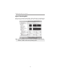
1
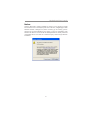
Motherboard User’s Guide This publication, including photographs, illustrations and software, is under the protection of international copyright laws, with all rights reserved. Neither this user’s guide, nor any of the material contained herein, may be reproduced without the express written consent of the manufacturer. The information in this document is subject to change without notice. The manufacturer makes no representations or warranties with respect to the contents hereof and specifically disclaims any implied warranties of merchantability or fitness for any particular purpose. Further, the manufacturer reserves the right to revise this publication and to make changes from time to time in the content hereof without obligation of the manufacturer to notify any person of such revision or changes. Trademarks IBM, VGA, and PS/2 are registered trademarks of International Business Machines. Intel, Pentium/II/III, Pentium 4, Celeron and MMX are registered trademarks of Intel Corporation. Microsoft, MS-DOS and Windows 98/ME/NT/2000/XP are registered trademarks of Microsoft Corporation. AMI is a trademark of American Megatrends Inc. It has been acknowledged that other brands or product names in this manual are trademarks or the properties of their respective owners. Static Electricity Precautions 1. Don’t take this motherboard and components out of their original staticproof package until you are ready to install them. 2. While installing, please wear a grounded wrist strap if possible. If you don’t have a wrist strap, discharge static electricity by touching the bare metal of the system chassis. 3. Carefully hold this motherboard by its edges. Do not touch those components unless it is absolutely necessary. Put this motherboard on the top of static-protection package with component side facing up while installing. Pre-Installation Inspection 1. Inspect this motherboard whether there are any damages to components and connectors on the board. 2. If you suspect this motherboard has been damaged, do not connect power to the system. Contact your motherboard vendor about those damages. Copyright © 2006 All Rights Reserved P13G+ Series, V1.0 March 2006 i Motherboard User’s Guide Table of Contents Trademark ............................................................................................................ i Static Electricity Precautions ......................................................................................... i Pre-Installation Inspection ............................................................................................. i Chapter 1: Introduction ..................................................................................... 1 Key Features .................................................................................................................... 1 Package Contents ........................................................................................................... 4 Chapter 2: Motherboard Installation .............................................................. 5 Motherboard Components ............................................................................................ 6 I/O Ports .......................................................................................................................... 8 Installing the Processor ................................................................................................. 9 Installing Memory Modules ........................................................................................ 1 0 Jumper Settings ............................................................................................................ 1 3 Install the Motherboard ............................................................................................... 1 4 Connecting Optional Devices ..................................................................................... 1 5 Install Other Devices .................................................................................................... 1 8 Expansion Slots ............................................................................................................ 2 0 Dual Monitor..................................................................................................... 22 Chapter 3: BIOS Setup Utility ....................................................................... 23 About the Setup Utility....................................................................................... 2 3 Updating the BIOS............................................................................................ 24 Using BIOS....................................................................................................... 25 Standard CMOS Features.................................................................................. 2 6 Advanced BIOS Features ............................................................................................ 2 8 Advanced Chipset Features ......................................................................................... 3 2 Integrated Peripherals ................................................................................................. 3 4 Power Management Setup .......................................................................................... 3 9 PnP/PCI Configurations .............................................................................................. 4 1 PC Health Status...................................................................................... .........42 Frequency Control ....................................................................................................... 4 4 Load Fail-Safe Defaults .............................................................................................. 4 5 Load Optimized Defaults ............................................................................................. 4 5 Set Supervisor Password .............................................................................................. 4 5 Set User Password............................................................................................. 45 Save & Exit Setup............................................................................................. 46 Exit Without Saving........................................................................................... 46 Chapter 4: Software & Applications .............................................................. 47 Introduction .................................................................................................................. 4 7 Installing Support Software ........................................................................................ 4 7 Bundled Software Installation .................................................................................... 4 9 ii Motherboard User’s Guide Notice: Owing to Microsoft’s certifying schedule is various to every supplier, we might have some drivers not certified yet by Microsoft. Therefore, it might happen under Windows XP that a dialogue box (shown as below) pop out warning you this software has not passed Windows Logo testing to verify its compatibility with Windows XP. Please rest assured that our RD department has already tested and verified these drivers. Just click the “Continue Anyway” button and go ahead the installation. iii Chapter 1: Introduction Chapter 1 Introduction This motherboard has an LGA775 socket for latest Intel Pentium 4/Celeron D/ Pentium D processors with Hyper-Threading Technology and Front-Side Bus (FSB) speeds up to 800/533/400 MHz. Hyper-Threading Technology, designed to take advantage of the multitasking features in Windows XP, gives you the power to do more things at once. This motherboard integrates the Intel 865G Northbridge along with Intel I/O Controller Hub 5 (ICH5) that supports the Serial ATA interface for high-performance and mainstream desktop PCs; the built-in USB 2.0 providing higher bandwidth, implementing Universal Serial Bus Specification Revision 2.0 and is compliant with UHCI 1.1 and EHCI 1.0. It supports 6-channel AC’97 Audio Codec and provides two IDE Ultra DMA 100/ 66/33 channel. It has one AGP 8X slot, one CNR and two 32-bit PCI slots. There is a full set of I/O ports including two PS/2 ports for mouse and keyboard, one VGA port, one serial port, one parallel port, one LAN port (optional), three audio jacks for micropone, line-in and line-out, and four back-panel USB 2.0 ports. In addition, onboard USB headers provide extra ports by connecting the extended USB module to the motherboard. It is a Micro ATX motherboard and has power connectors for an ATX power supply. Key Features The key features of this motherboard include: LGA775 Socket Processor Support • Supports the latest Intel Pentium 4/Celeron D/Pentium D Series processors with Hyper-Threading Technology • Supports up to 800/533/400 MHz Front-Side Bus . Note: Hyper-Threading technology enables the operating system into thinking it’s hooked up to two processors, allowing two threads to be run in parallel, both on separate ‘logical’ processors within the same physical processor Chipset There are Intel 865G Northbridge and Intel I/O Controller Hub 5 (ICH5) in the chipsets in accordance with an innovative and scalable architecture with proven reliability and performance. • Host Interface Support − One Intel Pentium 4 processor with 512-KB L2 cache on 0.13 micron process / Pentium 4 processor on 90 nm process • Hyper-Threading Technology 1 Motherboard User’s Guide • System Memory Controller Support − Dual-channel (6.4 GB/s wide) DDR memory interface − Single-channel (3.2 GB/s wide) operation supported − Supports DDR266, DDR333, DDR400 DIMM modules • PCI Bus Interface − Supports PCI Revision 2.3 Specification at 33 MHz • Integrated LAN Controller − 10/100 Mbp/s Faster Ethernet Support • Integrated Serial ATA Host Controllers − Independent DMA operation on two ports − Data transfer rates up to 1.5 Gb/s (150 MB/s) • Integrated IDE Controller − Ultra ATA100/66/33, BMIDE and PIO modes • USB 2.0 − Includes 4 UHCI Host Controllers, increasing the number of external • ports to eight AC-Link for Audio and Telephony Codecs − Support for 3 AC’97 2.3 codecs−533 MT/s (133 MHz) FSB and 800 MT/s (200 MHz) FSB − Supports Hyper-Threading Technology (HT Technology) − FSB Dynamic Bus Inversion (DBI) Memory Support • Two 184-pin DIMM sockets for DDR SDRAM DDR400/333/266 memory modules • Maximum installed memory is 2 GB Expansion Slots • One AGP 8X slot • Two 32-bit PCI slots • One CNR slot Onboard IDE channels • Two IDE Channels supporting ATA-33, ATA-66, ATA-100 • Supports PIO (Programmable Input/Output) and DMA (Direct Memory Access) modes • Supports IDE Ultra DMA bus mastering with transfer rates of 100/66/33 MB/s Serial ATA • Two Serial ATA Connectors • Transfer rate exceeding best ATA (1.5 Gb/s) with scalability to higher rates • Low pin count for both host and devices AC’97 Audio Codec • Compliant with AC’97 2.3 specification 2 Chapter 1: Introduction • • • • Front-Out, Surround-Out, MIC-In and LINE-In Jack Sensing Three analog line-level stereo inputs with 5-bit volume control: LINE_IN, CD, AUX Two analog line-level mono input Standard 48-Pin LQFP Onboard I/O Ports • Two PS/2 ports for mouse and keyboard • One serial port • One parallel port • One VGA port • One LAN port (optional) • Four back-panel USB2.0 ports • Audio jacks for microphone, line-in and line-out Fast Ethernet LAN (optional) • 10 Mb/s and 100 Mb/s operation • Integrated Fast Ethernet MAC, physical chip, and transceiver onto a single chip • Supports 10 Mb/s and 100 Mb/s N-way auto-negotiation • Support ACPI power management • Full Duplex Flow Control (IEEE 802.3x) and Half/Full duplex capability USB 2.0 • Compliant with Universal Serial Bus Specification Revision 2.0 • Compliant with Intel’s Enhanced Host Controller Interface Specification Revision 1.0 • Compliant with Universal Host Controller Interface Specification Revision 1.1 • PCI multi-function device consists of two UHCI Host Controller cores for full-/low-speed signaling and one EHCI Host Controller core for highspeed signaling • Root hub consists 4 downstream facing ports with integrated physical layer transceivers shared by UHCI and EHCI Host Controller, up to eight functional ports • Support PCI-Bus Power Management Interface Specification release 1.1 • Legacy support for all downstream facing ports BIOS Firmware This motherboard uses AWARD BIOS that enables users to configure many system features including the following: • Power management • Wake-up alarms • CPU parameters and memory timing • CPU and memory timing 3 Motherboard User’s Guide The firmware can also be used to set parameters for different processor clock speeds. Dimensions • Micro ATX form factor of 244 x 220 mm Note: Hardware specifications and software items are subject to change without notification. Package Contents Your motherboard package ships with the following items: The motherboard The User’s Guide One diskette drive ribbon cable (optional) One IDE drive ribbon cable The Software support CD Optional Accessories You can purchase the following optional accessories for this motherboard. The Extended USB module The CNR v.90 56K Fax/Modem card The Serial ATA cable The Serial ATA power cable Note: You can purchase your own optional accessories from the third party, but please contact your local vendor on any issues of the specification and compatibility. 4 Chapter 2: Motherboard Installation Chapter 2 Motherboard Installation To install this motherboard in a system, please follow these instructions in this chapter: Identify the motherboard components Install a CPU Install one or more system memory modules Make sure all jumpers and switches are set correctly Install this motherboard in a system chassis (case) Connect any extension brackets or cables to headers/connectors on the motherboard Install peripheral devices and make the appropriate connections to headers/connectors on the motherboard Note: 1 Before installing this motherboard, make sure jumper CLR_CMOS is under Normal setting. See this chapter for information about locating CLR_CMOS and the setting options. 2 Never connect power to the system during installation; otherwise, it may damage the motherboard. 5 Motherboard User’s Guide Motherboard Components 6 Chapter 2: Motherboard Installation ITEM 1 LABEL CPU Socket COMPONENTS LGA775 Socket for Intel Pentium 4/Celeron D/Pentium D CPUs CPU Fan connector(4PIN) 2 CPU_FAN 3 DIMM1/DIMM3 4 5 6 7 IR1 FDD1 ATX1 IDE1 184-pin DDR SDRAM sockets (Support DualChannel DDR400) Infrared header Floppy Disk Drive connector Standard 20-Pin ATX Power connector Primary IDE connector 8 IDE2 Secondary IDE connector 9 10 11 SPK1 CLR_CMOS BIOS_WP Speaker header Clear CMOS jumper BIOS protect jumper 12 13 SATA1~2 PANEL1 Serial ATA connectors Front Panel Switch/LED header 14 15 16 17 18 USB3~4 CNR1 AUDIO1 AUX_IN CD_IN Front Panel USB headers CNR slot Front Panel Audio header Auxiliary In header Analog Audio Input header 19 20 21 22 23 SPDIFO1 PCI1~2 AGP1 SYS_FAN ATX12V SPDIF out header 32-bit add-on card slots Accelerated Graphics Port slot System Fan connector 4-pin +12V power connector 7 Motherboard User’s Guide I/O Ports The illustration below shows a side view of the built-in I/O ports on the motherboard. (optional) PS/2 Mouse Use the upper PS/2 port to connect a PS/2 pointing device. PS/2 Keyboard Use the low er PS/2 port to connect a PS/2 keyboard. Parallel Port (LPT1) Use the Parallel port to connect printers or other parallel communications devices. COM1 Use the COM port to connect serial devices such as mice or fax/modems. COM1 is identified by the system as COM1. VGA1 Use the VGA1 port to connect VGA devices. LAN Port (optional) Connect an RJ-45 jack to the LAN port to connect your computer to the Netw ork. USB Ports Use the USB ports to connect USB devices. Audio Ports Use these three audio jacks to connect audio devices. The first jack is for stereo Line-In signal, the second jack for stereo Line-Out signal, and the third jack for Microphone. 8 Chapter 2: Motherboard Installation Installing the Processor This motherboard has an LGA775 socket for the latest Intel Pentium 4/Celeron D/Pentium D processors. When choosing a processor, consider the performance requirements of the system. Performance is based on the processor design, the clock speed and system bus frequency of the processor, and the quantity of internal cache memory and external cache memory. CPU Installation Procedure Follow these instructions to install the CPU: 1 LGA775 Socket CPUFAN pin1 A. Unload the cap • Use thumb & forefinger to hold the lifting tab of the cap. • Lift the cap up and remove the cap completely from the socket. B. Open the load plate • Use thumb & forefinger to hold the hook of the lever, pushing down and pulling aside unlock it. • Lift up the lever. • Use thumb to open the load plate. Be careful not to touch the contacts. 9 Motherboard User’s Guide C. Install the CPU on the socket • Orientate CPU package to the socket. Make sure you match triangle marker to pin 1 location. D. Close the load plate • Slightly push down the load plate onto the tongue side, and hook the lever. • CPU is locked completely. E. Apply thermal grease on top of the CPU. F. Fasten the cooling fan supporting base onto the CPU socket on the motherboard. G. Make sure the CPU fan is plugged to the CPU fan connector. Please refer to the CPU cooling fan user’s manual for more detail installation procedure. Note1:To achieve better airflow rates and heat dissipation, we suggest that you use a high quality fan with 3800 rpm at least. CPU fan and heatsink installation procedures may vary with the type of CPU fan/heatsink supplied. The form and size of fan/heatsink may also vary. Note2:The fan connector supports the CPU cooling fan of 1.1A~2.2A (26.4W max.) at +12V. Installing Memory Modules This motherboard accommodates two 184-pin DIMM sockets (Dual Inline Memory Module) for unbuffered DDR400/333/266 memory modules (Double Data Rate SDRAM), and maximum 2.0 GB installed memory. DDR SDRAM is a type of SDRAM that supports data transfers on both edges of each clock cycle (the rising and falling edges), effectively doubling the memory chip’s data throughput. This motherboard provides the Dual Channel Technology; when activating it, the bandwidth of memory bus will be doubled to 6.4 GB/s and Frequency 200 MHz. 10 Chapter 2: Motherboard Installation DIMM1/3 Memory Module Installation Procedure These modules can be installed with up to 2 GB system memory. Refer to the following to install the memory module. 1. Push down the latches on both sides of the DIMM socket. 2. Align the memory module with the socket. There is a notch on the DIMM socket that you can install the DIMM module in the correct direction. Match the cutout on the DIMM module with the notch on the DIMM socket. 3. Install the DIMM module into the socket and press it firmly down until it is seated correctly. The socket latches are levered upwards and latch on to the edges of the DIMM. 4. Install any remaining DIMM modules. 11 Motherboard User’s Guide Table A: DDR (memory module) QVL (Qualified Vendor List) The following DDR400 memory module have been tested and qualified for use with this motherboard. Size 256 MB 512 MB 1 GB Vendor Module Name Apacer AM3A568ACT05A Corsair Platinum CMX256-3200C2PT GEIL G208L364D1TG5NKT3C GEIL GE08L3264D1WL5NKT3H71 GEIL GL3L32G88TG-5A Kingston D3208DL2T-5 0323PT01 Kingston Winbond W942508BH-5 Kingston Samsung K4H560838D-TCC4 Ramaxel Samsung K4H560838D-TCC4 Ramaxel MIC-R 46V32M8TG-5BC Samsung K4H560838E-TCCC Samsung K4H560838D-TCCC Soutec M2G9108AKAS09F083S9DT COSAIR Platinum CMX512-3200C2PT GEIL GE16L6464D2WL5NKT3H66 Hynix HY5DU56822BT-D43 Kingston Winbond W942508BH-5 Kingston Samsung K4H560838D-TCC4 Kingmax KDL388P4EA-50 Samsung K4H560838E-TCCC TwinMOS M2G9J16AKATT9F083S9DT A-DATA Vitesta 12 Chapter 2: Motherboard Installation Jumper Settings Connecting two pins with a jumper cap is SHORT; removing a jumper cap from these pins, OPEN. CLR_CMOS 1 1 BIOS_WP CLR_CMOS: Clear CMOS Jumper Use this jumper to clear the contents of the CMOS memory. You may need to clear the CMOS memory if the settings in the Setup Utility are incorrect and prevent your motherboard from operating. To clear the CMOS memory, disconnect all the power cables from the motherboard and then move the jumper cap into the CLEAR setting for a few seconds. Function Jum per Normal Short Pins 1-2 Clear CMOS Short Pins 2-3 Note: To avoid the system unstability after clearing CMOS, we recommend users to enter the main BIOS setting page to “Load Optimal De-faults” and then “Save Changes and Exit”. BIOS_WP: BIOS FLASH PROTECT Jumper Use this jumper to set the BIOS FLASH PROTECT function. Function DISABLE ENABLE Jum per OPEN SHORT 13 Motherboard User’s Guide Install the Motherboard Install the motherboard in a system chassis (case). The board is a Micro ATX size motherboard. You can install this motherboard in an ATX case. Make sure your case has an I/O cover plate matching the ports on this motherboard. Install the motherboard in a case. Follow the case manufacturer’s instructions to use the hardware and internal mounting points on the chassis. ATX12V ATX1 1 SYS_FAN PANEL1 1 Connect the power connector from the power supply to the ATX1 connector on the motherboard. The ATX12V is a +12V connector for CPU Vcore power. If there is a cooling fan installed in the system chassis, connect the cable from the cooling fan to the SYS_FAN fan power connector on the motherboard. Connect the CPU fan connector to CPU_FAN. Connect the case switches and indicator LEDs to the PANEL1 header. Please refer to the following list of the PANEL1 pin assignments. Pin 1 3 5 7 9 Signal HD_LED_P(+) HD_LED_N(-) RESET_SW_N(-) RESET_SW_P(+) RSVD_DNU Pin 2 4 6 8 10 14 Signal FP PWR/SLP(+) FP PWR/SLP(-) POWER_SW_P(+) POWER_SW_N(-) KEY Chapter 2: Motherboard Installation Connecting Optional Devices Refer to the following for information on connecting the motherboard’s optional devices: 1 IR1 SPK1 1 1 AUX_IN 1 AUDIO1 1 1 1 USB3 USB4 SPDIFO1 AUDIO1: Front Panel Audio Header This header allows the user to install auxiliary front-oriented microphone and line-out ports for easier access. Pin 1 3 5 7 9 Signal AUD_MIC AUD_MIC_BIAS AUD_FPOUT_R HP_ON AUD_FPOUT_L Pin 2 4 6 8 10 Signal AUD_GND AUD_VCC AUD_RET_R KEY AUD_RET_L USB3/USB4: Front Panel USB Headers The motherboard has USB ports installed on the rear edge I/O port array. Additionally, some computer cases have USB ports at the front of the case. If you have this kind of case, use auxiliary USB headers USB3/USB4 to connect the front-mounted ports to the motherboard. 15 Motherboard User’s Guide Here is a list of headers USB3/USB4 pin assignments. Pin 1 3 5 7 9 1 2 3 Signal USB DUAL VCC USBP4USBP4+ GROUND KEY Pin 2 4 6 8 10 Signal USB DUAL VCC USBP5USBP5+ GROUND USBOC45# Locate the USB3/USB4 header on the motherboard. Plug the bracket cable onto the USB3/USB4 header. Remove a slot cover from one of the expansion slots on the system chassis. Install an extension bracket in the opening. Secure the extension bracket to the chassis with a screw. SPK1: Speaker Header Connect the cable from the PC speaker to the SPK1 header on the motherboard. Pin 1 2 3 4 Signal Sigal Key GND VCC IR1: Infrared Header The infrared port allows the wireless exchange of information between your computer and similarly equipped devices such as printers, laptops, Personal Digital Assistants (PDAs), and other computers. Pin 1 3 5 1 2 Signal NC +5V IRTX Pin 2 4 6 Signal KEY GND IRRX Locate the infrared port-IR1 header on the motherboard. If you are adding an infrared port, connect the ribbon cable from the port to the IR1 header and then secure the port to an appropriate place in your system chassis. 16 Chapter 2: Motherboard Installation SPDIFO1: SPDIF out header This is an optional header that provides an S/PDIF (Sony/Philips Digital Interface) output to digital multimedia device through optical fiber or coaxial connector. Pin 1 2 3 4 Signal SPDIF +5VA Key GND AUX_IN: Auxiliary In header This connector is an additional line-in audio connector. It allows you to attach a line-in cable when your rear line-in jack is set as line out port for 4-channel function. Pin 1 2 3 4 Signal AUX_L GND GND AUX_R 17 Motherboard User’s Guide Install Other Devices Install and connect any other devices in the system following the steps below. 1 FDD1 1 1 SATA2 IDE2 IDE1 SATA1 Floppy Disk Drive The motherboard ships with a floppy disk drive cable that can support one or two drives. Drives can be 3.5" or 5.25" wide, with capacities of 360K, 720K, 1.2MB, 1.44MB, or 2.88MB. Install your drives and connect power from the system power supply. Use the cable provided to connect the drives to the floppy disk drive connector FDD1. IDE Devices IDE devices include hard disk drives, high-density diskette drives, and CD-ROM or DVD-ROM drives, among others. The motherboard ships with an IDE cable that can support one or two IDE devices. IDE1 can support up to 2 IDE devices, data transporting in ATA-33/66/100 mode. Serial ATA Devices The Serial ATA (Advanced Technology Attachment) is the standard interface for the IDE hard drives, which is designed to overcome the design limitations 18 Chapter 2: Motherboard Installation while enabling the storage interface to scale with the growing media rate demands of PC platforms. It provides you a faster transfer rate of 1.5 Gb/s. If you have installed a Serial ATA hard drive, you can connect the Serial ATA cables to the Serial ATA hard drive or the connecter on the motherboard. On the motherboard, locate the Serial ATA connectors SATA1-2, which support new Serial ATA devices for the highest data transfer rates, simpler disk drive cabling and easier PC assembly. It eliminates limitations of the current Parallel ATA interface, but maintains register compatibility and software compatibility with Parallel ATA. Analog Audio Input Header If you have installed a CD-ROM drive or DVD-ROM drive, you can connect the drive audio cable to the onboard sound system. 1 CD_IN When you first start up your system, the BIOS should automatically detect your CD-ROM/DVD drive. If it doesn’t, enter the Setup Utility and configure the CDROM/DVD drive that you have installed. On the motherboard, locate the 4-pin header CD_IN. Pin 1 2 3 Signal CD IN L GND GND 4 CD IN R 19 Motherboard User’s Guide Expansion Slots This motherboard has one CNR1, one AGP1 and two 32-bit PCI slots. AGP1 PCI1 PCI2 CNR1 20 Chapter 2: Motherboard Installation Follow the steps below to install a CNR1/AGP1/PCI expansion card. 1 Locate the CNR1, AGP1 and PCI slots on the motherboard. 2 Remove the blanking plate of the slot from the system chassis. 3 Install the edge connector of the expansion card into the slot. Ensure the edge connector is correctly seated in the slot. 4 Secure the metal bracket of the card to the system chassis with a screw. AGP1 Slot (AGP 8X) The AGP1 slot is used to install AGP graphics card that emulates the AGP function. In order to get better performance and compatibility on our special design AGP1 slot, we recommend you should use one of the AGP graphics cards that have been tested by our company. 21 Motherboard User’s Guide PCI1-3 Slots You can install the 32-bit PCI interface expansion cards in the slots. CNR1 Slot You can install CNR1 (Communications and Networking Riser) cards including LAN, Modem and Audio functions, in this slot. 22 Chapter 3: BIOS Setup Utility Chapter 3 BIOS Setup Utility About The Setup Utility The computer uses the latest Award BIOS with support for Windows Plug and Play. The CMOS chip on the motherboard contains the ROM setup instructions for configuring the motherboard BIOS. The BIOS (Basic Input and Output System) Setup Utility displays the system’s configuration status and provides you with options to set system parameters. The parameters are stored in battery-backed-up CMOS RAM that saves this information when the power is turned off. When the system is turned back on, the system is configured with the values you stored in CMOS. The BIOS Setup Utility enables you to configure: · Hard drives, diskette drives and peripherals · Video display type and display options · Password protection from unauthorized use · Power Management features The settings made in the Setup Utility affect how the computer performs. Before using the Setup Utility, ensure that you understand the Setup Utility options. This chapter provides explanations for Setup Utility options. The Standard Configuration A standard configuration has already been set in the Setup Utility. However, we recommend that you read this chapter in case you need to make any changes in the future. This Setup Utility should be used: · when changing the system configuration · when a configuration error is detected and you are prompted to make changes to the Setup Utility · when trying to resolve IRQ conflicts · when making changes to the Power Management configuration · when changing the password or making other changes to the Security Setup Entering The Setup Utility When you power on the system, BIOS enters the Power-On Self Test (POST) routines. POST is a series of built-in diagnostics performed by the BIOS. After the POST routines are completed, the following message appears: 23 Motherboard User’s Guide Press DEL to enter SETUP Pressing the delete key accesses the BIOS Setup Utility: Phoenix - AwardBIOS CMOS Setup Utility Standard CMOS Features Advanced BIOS Features Advanced Chipset Features Integrated Peripherals Power Management Setup PnP/PCI Configurations PC Health Status Esc:Quit Frequency Control Load Fail-Safe Defaults Load Optimized Defaults Set Supervisor Password Set User Password Save & Exit Setup Exit Without Saving F9: Menu in BIOS : Select Item F10: Save & Exit Setup Time, Date, Hard Disk Type ... BIOS Navigation Keys The BIOS navigation keys are listed below: KEY ECS FUNCTION Exits the current menu Scrolls through the items on a menu +/-/PU/PD Modifies the selected field’s values F10 Saves the current configuration and exits setup F1 F5 Displays a screen that describes all key functions Loads previously saved values to CMOS F6 Loads a minimum configuration for troubleshooting F7 Loads an optimum set of values for peak performance Updating the BIOS You can download and install updated BIOS for this motherboard from the manufacturer’s Web site. New BIOS provides support for new peripherals, improvements in performance, or fixes for known bugs. Install new BIOS as follows: 1 If your motherboard has a BIOS protection jumper, change the setting to allow BIOS flashing. 2 If your motherboard has an item called Firmware Write Protect in Advanced BIOS features, disable it. (Firmware Write Protect prevents BIOS from being overwritten. 3 Create a bootable system disk. (Refer to Windows online help for information on creating a bootable system disk.) 24 Chapter 3: BIOS Setup Utility 4 5 6 7 8 Download the Flash Utility and new BIOS file from the manufacturer’s Web site. Copy these files to the system diskette you created in Step 3. Turn off your computer and insert the system diskette in your computer’s diskette drive. (You might need to run the Setup Utility and change the boot priority items on the Advanced BIOS Features Setup page, to force your computer to boot from the floppy diskette drive first.) At the A:\ prompt, type the Flash Utility program name and press <Enter>. Type the filename of the new BIOS in the “File Name to Program” text box. Follow the onscreen directions to update the motherboard BIOS. When the installation is complete, remove the floppy diskette from the diskette drive and restart your computer. If your motherboard has a Flash BIOS jumper, reset the jumper to protect the newly installed BIOS from being overwritten. Using BIOS When you start the Setup Utility, the main menu appears. The main menu of the Setup Utility displays a list of the options that are available. A highlight indicates which option is currently selected. Use the cursor arrow keys to move the highlight to other options. When an option is highlighted, execute the option by pressing <Enter>. Some options lead to pop-up dialog boxes that prompt you to verify that you wish to execute that option. Other options lead to dialog boxes that prompt you for information. Some options (marked with a triangle ) lead to submenus that enable you to change the values for the option. Use the cursor arrow keys to scroll through the items in the submenu. In this manual, default values are enclosed in parenthesis. Submenu items are denoted by a triangle . 25 Motherboard User’s Guide Standard CMOS Features This page displays a table of items defining basic information about your system. Phoenix - AwardBIOS CMOS Setup Utility Standard CMOS Features Date ( mm: dd: yy ) Time ( hh: mm: ss ) IDE Channel 0 Master IDE Channel 0 Slave IDE Channel 1 Master IDE Channel 1 Slave Drive A Floppy 3 Mode Support Video Halt On [ 1.44 M, 3.5 in. ] [ Disabled ] [EGA/VGA] [All Errors] Base Memory Extended Memory Total Memory 640K 261120K 262144K : Move Enter: Select F5:Previous Values Tue, Mar 16 2006 10 : 21 : 36 Item Help Menu Level Change the day, month, year and century +/-/PU/PD:Value F10:Save F6:Fail-Safe Defaults ESC:Exit F1: General Help F7:Optimized Defaults Date and Time The Date and Time items show the current date and time on the computer. If you are running a Windows OS, these items are automatically updated whenever you make changes to the Windows Date and Time Properties utility. IDE Devices Your computer has two IDE channels (Primary and Secondary) and each channel can be installed with one or two devices (Master and Slave). In addition, this motherboard supports two SATA channels (Primary and Secondary) and each channel allows one SATA device to be installed. Use these items to configure each device on the IDE channel. 26 Chapter 3: BIOS Setup Utility Press <Enter> to display the IDE submenu: Phoenix-AwardBIOS CMOS Setup Utility IDE Channel 0 Master IDE HDD Auto-Detection [ Press Enter] IDE Channel 0 Master Access Mode [Auto] [Auto] Capacity 0 MB Cylinder Head Precomp Landing Zone Sector 0 0 0 0 0 : Move Enter: Select +/-/PU/PD:Value F5:Previous Values F6:Fail-Safe Defaults Item Help Menu Level To auto-detect the HDD’s size, head...on this channel F10:Save ESC:Exit F1: General Help F7:Optimized Defaults IDE HDD Auto-Detection Press <Enter> while this item is highlighted to prompt the Setup Utility to automatically detect and configure an IDE device on the IDE channel. If you are setting up a new hard disk drive that supports LBA mode, more than one line will appear in the parameter box. Choose the line that lists LBA for an LBA drive. IDE Channel 0/1 Master/Slave (Auto) Leave this item at Auto to enable the system to automatically detect and configure IDE devices on the channel. If it fails to find a device, change the value to Manual and then manually configure the drive by entering the characteristics of the drive in the items described below. Refer to your drive’s documentation or look on the drive casing if you need to obtain this information. If no device is installed, change the value to None. Before attempting to configure a hard disk drive, ensure that you have the configuration information supplied by the manufacturer of your hard drive. Incorrect settings can result in your system not recognizing the installed hard disk. Access Mode (Auto) This item defines ways that can be used to access IDE hard disks such as LBA (Large Block Addressing). Leave this value at Auto and the system will automatically decide the fastest way to access the hard disk drive. Press <Esc> to return to the Standard CMOS Features page. 27 Motherboard User’s Guide Drive A (1.44M, 3.5 in./None) This item defines the characteristics of any diskette drive attached to the system. Floppy 3 Mode Support (Disabled) Floppy 3 mode refers to a 3.5-inch diskette with a capacity of 1.2 MB. Floppy 3 mode is sometimes used in Japan. Video (EGA/VGA) This item defines the video mode of the system. This motherboard has a built-in VGA graphics system; you must leave this item at the default value. Halt On (All Errors) This item defines the operation of the system POST (Power On Self Test) routine. You can use this item to select which types of errors in the POST are sufficient to halt the system. Base Memory, Extended Memory, and Total Memory These items are automatically detected by the system at start up time. These are display-only fields. You cannot make changes to these fields. Press <Esc> to return to the AwardBIOS CMOS Setup Utility page. Advanced BIOS Features This option defines advanced information about your system. Phoenix-AwardBIOS CMOS Setup Utility Advanced BIOS Features CPU Feature Hard Disk Boot Priority CPU L3 Cache Hyper-Threading Technology Quick Power On Self Test First Boot Device Second Boot Device Third Boot Device Boot Other Device Boot Up Floppy Seek Boot Up NumLock Status Gate A20 Option Typematic Rate Setting X Typematic Rate (Chars/Sec ) X Typematic Delay (Msec) Security Option APIC Mode OS Select For DRAM > 64MB HDD S.M.A.R.T. Capability Report No FDD For WIN 95 Delay For HDD (Secs) Small Logo (EPA) Show [Press Enter] [Press Enter] [Enabled] [Enabled] [Enabled] [Floppy] [Hard Disk] [CDROM] [Enabled] [Disabled] [On] [Fast] [Disabled] 6 250 [Setup] [Enabled] [Non-OS2] [Disabled] [Yes] [4] [Disabled] : Move Enter: Select +/-/PU/PD:Value F5:Previous Values F6:Fail-Safe Defaults 28 Item Help Menu Level 123 123 123 F10:Save ESC:Exit F1: General Help F7:Optimized Defaults Chapter 3: BIOS Setup Utility CPU Feature (Press Enter) Users please note that this function is only available for Prescott CPUs. Scroll to this item and press <Enter> to view the following screen: Phoenix-AwardBIOS CMOS Setup Utility CPU Feature Delay Prior to thermal Thermal Management TM2 Bus Ratio TM2 Bus VID Limit CPUID MaxVal C1E Support Execute Disabled Bit Vanderpool Technology Intel (R) SpeedStep (tm) Tech. [16 Min] [Thermal Monitor 2] [0 X] [0.8375V] [Disabled] [Enabled] [Disabled] [Enabled] [Enabled] : Move Enter: Select +/-/PU/PD:Value F5:Previous Values F6”Fail-Safe Defaults Item Help Menu Level F10:Save ESC:Exit F1: General Help F7:Optimized Delay Prior to Thermal (16 Min) This item enables you to set the delay time before the CPU enters auto thermal mode. Thermal Management (Thermal Monitor 2) This item displays CPU’s temperature and enables you to set a safe temperature to Prescott CPU. TM2 Bus Ratio (0 X) This item helps you to set the frequency (bus ratio) of the throttled performance that will be initiated when the on-die sensor goes from not hot to hot. You may set the bus ratio number from 0-255. This feature is available when CPU supports Thermal Monitor 2. TM2 Bus VID (0.8375V) This item helps you to set the voltage of the throttled performance that will be initiated when the on-die sensor goes from not hot to hot. This feature is available when CPU supports Thermal Monitor 2. Limit CPUID MaxVal (Disabled) This item can support Prescott CPUs for old OS. Users please note that under NT 4.0, it must be set “Enabled”, while under WinXP, it must be set “Disabled”. C1E Support (Enabled) This item enables or disables the CPU C1E function. Execute Disabled Bit (Disabled) Users please leave this item in its default setting under Windows XP OS. Change the value to “Disabled” if users are to install Linux OS. 29 Motherboard User’s Guide Vanderpool Technology (Enabled) This item enables or disables the Vanderpool Technology. When disabled, forcess the VT function will close. Intel (R) SpeedStep (tm) Tech. (Enabled) This item enables or disables the Intel (R) SpeedStep (tm) technology. When enabled, allows enhance Intel SpeedStep Technology transitions. Press <Esc> to return to the AwardBIOS CMOS Setup Utility page. Hard Disk Boot Priority (Press Enter) Scroll to this item and press <Enter> to view the following screen: Phoenix-AwardBIOS CMOS Setup Utility Hard Disk Boot Priority 1. 2. 3. 4. 5. 6. 7. 8. Item Help Pri. Master : Pri. Slave : Sec. Master: Sec. Slave : USBHDD0 : USBHDD1 : USBHDD2 : Bootable Add-in Cards : Move Menu Level Use < > or < > to select a device, then press <+> to move it up, or <-> to move it down the list. Press <ESC> to exit this menu. PU/PD/+/-/: Change Priority F10:Save ESC:Exit CPU L3 Cache (Enabled) All Prescott processors that can be installed in this mainboard use Level 3 (L3) cache memory to improve performance. Leave this item at the default value for better performance. This item is only available when you use L3 cache supported CPU. Hyper-Threading Technology (Enabled) This item is only available when the chipset supports Hyper-Threading and you are using a Hyper-Threading CPU. Quick Power On Self Test (Enabled) Enable this item to shorten the power on testing (POST) and have your system start up faster. You might like to enable this item after you are confident that your system hardware is operating smoothly. First/Second/Third Boot Device (Floppy/Hard Disk/CDROM) Use these three items to select the priority and order of the devices that your system searches for an operating system at start-up time. 30 Chapter 3: BIOS Setup Utility Boot Other Device (Enabled) When enabled, the system searches all other possible locations for an operating system if it fails to find one in the devices specified under the First, Second, and Third boot devices. Boot Up Floppy Seek (Disabled) If this item is enabled, it checks the size of the floppy disk drives at start-up time. You don’t need to enable this item unless you have a legacy diskette drive with 360K capacity. Boot Up NumLock Status (On) This item defines if the keyboard Num Lock key is active when your system is started. Gate A20 Option (Fast) This item defines how the system handles legacy software that was written for an earlier generation of processors. Leave this item at the default value. Typematic Rate Setting (Disabled) If this item is enabled, you can use the following two items to set the typematic rate and the typematic delay settings for your keyboard. • Typematic Rate (Chars/Sec): Use this item to define how many characters per second are generated by a held-down key. • Typematic Delay (Msec): Use this item to define how many milliseconds must elapse before a held-down key begins generating repeat characters. Security Option (Setup) If you have installed password protection, this item defines if the password is required at system start up, or if it is only required when a user tries to enter the Setup Utility. APIC Mode (Enabled) This item allows you to enable or disable the APIC (Advanced Programmable Interrupt Controller) mode. APIC provides symmetric multi-processing (SMP) for systems, allowing support for up to 60 processors. OS Select For DRAM > 64 MB (Non-OS2) This item is only required if you have installed more than 64 MB of memory and you are running the OS/2 operating system. Otherwise, leave this item at the default. HDD S.M.A.R.T Capability (Disabled) The S.M.A.R.T. (Self-Monitoring, Analysis, and Reporting Technology) system is a diagnostics technology that monitors and predicts device performance. S.M.A.R.T. software resides on both the disk drive and the host computer. 31 Motherboard User’s Guide Report No FDD For WIN 95 (Yes) This item determines whether the BIOS will report no FDD for Windows 95 OS. Delay for HDD (Secs) (4) Users may set a delay from 1 to 15 seconds in the cold boot process. Some hard disk drives need extra time to spin up in order to identify correctly. If the system does not start after the memory test, try to add tomes in this field. Small Logo (EPA) Show (Disabled) Enables or disables the display of the EPA logo during boot. Press <Esc> to return to the AwardBIOS CMOS Setup Utility page. Advanced Chipset Features These items define critical timing parameters of the motherboard. You should leave the items on this page at their default values unless you are very familiar with the technical specifications of your system hardware. If you change the values incorrectly, you may introduce fatal errors or recurring instability into your system. Phoenix-AwardBIOS CMOS Setup Utility Advanced Chipset Features DRAM Timing Selectable CAS Latency Time Active to Precharge Delay DRAM RAS# to CAS# Delay DRAM RAS# Precharge Memory Frequency For System BIOS Cacheable Video BIOS Cacheable AGP Aperature Size (MB) Init Display First [By SPD] [2] [8] [4] [4] [Auto] [Disabled] [Enabled] [128] [PCI Slot] ** Photon Acceleration Technology ** Fast Chip Select CPC Addr/Control Turbo Mode [Auto] [Auto] [Auto] ** On-Chip VGA Setting ** On-Chip Frame Buffer Size Boot Display [8MB] [Auto] Item Help Menu Level : Move Enter: Select +/-/PU/PD:Value F10:Save ESC:Exit F1: General Help F5:Previous Values F6:Fail-Safe Defaults F7:Optimized Defaults DRAM Timing Selectable (By SPD) Enables you to select the CAS latency time in HCLKs of 2, 2.5, or 3. The value is set at the factory depending on the DRAM installed. Do not change the values in this field unless you change specifications of the installed DRAM or the installed CPU. 32 Chapter 3: BIOS Setup Utility • CAS Latency Time (2): This item controls the timing delay (in clock cycles) before the DRAM starts a read command after receiving it. • Active to Precharge Delay (8): This precharge time is the number of cycles it takes for DRAM to accumulate its charge before refresh. • DRAM RAS# to CAS# Delay (4): This field lets you insert a timing delay between the CAS and RAS strobe signals, used when DRAM is written to, read from, or refreshed. Disabled gives faster performance; and Enabled gives more stable performance. • DRAM RAS# Precharge (4): Select the number of CPU clocks allocated forthe Row Address Strobe (RAS#) signal to accumulate its charge before the DRAM is refreshed. If insufficient time is allowed, refresh may be incomplete and data lost. Memory Frequency For (Auto) This item sets the main memory frequency. When you used an external graphics card, you can adjust this to enable the best performance for your system. System BIOS Cacheable (Disabled) When this item is enabled, the System BIOS will be cached for faster execution. Video BIOS Cacheable (Enabled) When this is enabled, the Video RAM will be cached resulting to better performance. However, if any program was written to this memory area, this may result to system error. AGP Aperture Size (MB) (128) This item defines the size of the aperture if you use an AGP graphics adapter. The AGP aperture refers to a section of the PCI memory address renge used for graphics memory. We recommend that you leave this item at the default value. Init Display First (PCI Slot) This item allows you to choose the primary display card. Fast Chip Select (Auto) This item allows you to read the Data transfer from CPU to GMCH. CPC Addr/Control (Auto) This item allows you to increase the performance when DDR400 DIMM is installed and set this item to “Enabled”. However, this might cause the system to become UNSTEADY. Turbo Mode (Auto) This item allows you to increase the performance of CPU L2 cache timing at high speed. On-Chip Frame Buffer Size (8MB) This item allows you to set the onboard frame buffer size, ranging from 1MB, 8MB, to 16MB. 33 Motherboard User’s Guide Boot Display (Auto) This item allows you to set the boot display function to be “Auto”, “CRT”, “EFP”, “TV”, “CRT+EFP”, or “CRT+TV”. Press <Esc> to return to the AwardBIOS CMOS Setup Utility page. Integrated Peripherals These options display items that define the operation of peripheral components on the system’s input/output ports. Phoenix-AwardBIOS CMOS Setup Utility Integrated Peripherals OnChip IDE Device Onboard Device SuperIO Device Item Help [Press Enter] [Press Enter] [Press Enter] Menu Level : Move Enter: Select +/-/PU/PD:Value F5:Previous Values F6:Fail-Safe Defaults F10:Save ESC:Exit F1: General Help F7:Optimized Defaults OnChip IDE Device Scroll to this item and press <Enter> to view the following screen: Phoenix-AwardBIOS CMOS Setup Utility OnChip IDE Device IDE HDD Block Mode On-chip Primary PCI IDE IDE Primary Master PIO IDE Primary Slave PIO IDE Primary Master UDMA IDE Primary Slave UDMA On-chip Secondary PCI IDE IDE Secondary Master PIO IDE Secondary Slave PIO IDE Secondary Master UDMA IDE Secondary Slave UDMA ATA 66/100 Cable Msg [Enabled] [Enabled] [Auto] [Auto] [Auto] [Auto] [Enabled] [Auto] [Auto] [Auto] [Auto] [Enabled] *** On-Chip Serial ATA Setting*** SATA Mode On-chip Serial ATA Serial ATA Port0 Mode Serial ATA Port1 Mode [IDE] [Disabled] [Primary Master] Primary Master Item Help Menu Level If your IDE hard drive supports block mode select. Enabled for automatic detection of block read/writes per sector the drive can support. : Move Enter: Select +/-/PU/PD:Value F10:Save ESC:Exit F1: General Help F5:Previous Values F6:Fail-Safe Defaults F7:Optimized Defaults 34 Chapter 3: BIOS Setup Utility IDE HDD Block Mode (Enabled) Block mode is also called block transfer, multiple commands, or multiple sector read/write. If your IDE hard drive supports block mode (most new drives do), select Enabled for automatic detection of the optimal number of block read/write per sector the drive can support. On-Chip Primary/Secondary PCI IDE (Enabled) This integrated peripheral controller contains an IDE interface with support for two IDE channels. Select Enabled to activate each channel seperately. IDE Primary/Secondary Master/Slave PIO (Auto) Each IDE channel supports a master device and a slave device. These four items let you assign the kind of PIO (Programmed Input/Output) was used by the IDE devices. Choose Auto to let the system auto detect which PIO mode is best, or select a PIO mode from 0-4. IDE Primary/Secondary Master/Slave UDMA (Auto) Each IDE channel supports a master device and a slave device. This mainboard supports UltraDMA technology, which provides faster access to IDE devices. If you install a device that supports UltraDMA, change the appropriate item on this list to Auto. You may have to install the UltraDMA driver supplied with this mainboard in order to use an UltraDMA device. ATA 66/100 Cable Msg (Enabled) This item enalbes or disabled the display of the ATA 66/100 Cable Msg. If you install a device that supports UDMA, change the appropriate item on this list to Auto. You may have to install the UDMA driver supplied with this motherboard in order to use an UDMA device. SATA Mode (IDE) Use this item to select the mode of the Serial ATA. On-Chip Serial ATA (Disabled) Enables or disables the built-in on-chip Serial ATA. Serial ATA Port0/Port1 Mode (Primary Master) Use this item to select the SATA0 master or SATA1 master. Press <Esc> to return to the AwardBIOS CMOS Setup Utility page. 35 Motherboard User’s Guide Onboard Device Scroll to this item and press <Enter> to view the following screen: Phoenix-AwardBIOS CMOS Setup Utility Onboard Device USB Controller USB 2.0 Controller USB Keyboard Support USB Mouse Support AC97 AUDIO AC97 Modem Onboard LAN Device Onboard LAN Boot ROM Onboard 1394 Device [Enabled] [Enabled] [Enabled] [Enabled] [Auto] [Auto] [Enabled] [Disabled] [Enabled] : Move Enter: Select +/-/PU/PD:Value F5:Previous Values F6:Fail-Safe Defaults Item Help Menu Level F10:Save ESC:Exit F1: General Help F7:Optimized Defaults USB Controller (Enabled) This item enables the USB controller. Leave this at the default “Enabled” if you want to connect USB devices to you computer. USB 2.0 Controller (Enabled) Enable this item if you want to use the USB 2.0 USB Keyboard Support (Enabled) This item allows the BIOS to interact with a USB keyboard or mouse to work with MS-DOS based utilities and non-Windows modes. USB Mouse Support (Enabled) Enable this item if you plan to use a mouse connected through the USB port in a legacy operating system (such as DOS) that does not support Plug and Play. AC97 Audio (Auto) This option allows you to control the onboard AC97 audio. Disable this item if you are going to install a PCI audio add-on card. AC97 Modem (Auto) Use this item to enable or disabled the onboard AC97 modem device. Onboard LAN Device (Enabled) This option allows you to enable or disable the onboard LAN function. Onboard LAN Boot ROM (Disabled) Use this item to enable and disable the booting from the onboard LAN or a network add-in card with a remote boot ROM installed. Onboard 1394 Device (Enabled) This option allows you to enable or disable the onboard 1394 function. 36 Chapter 3: BIOS Setup Utility Press <Esc> to return to the AwardBIOS CMOS Setup Utility page. SuperIO Device Scroll to this item and press <Enter> to view the following screen: Phoenix-AwardBIOS CMOS Setup Utility SuperIO Device POWER ON Function KB Power ON Password Hot key Power ON Onboard FDC Controller Onboard Serial Port1 UART 2 Mode Controller UART Mode Select RxD , TxD Active IR Transmission Delay UR2 Duplex Mode Use IR Pins Onboard Parallel Port Parallel Port Mode ECP Mode Use DMA Power On After Power Fail : Move Enter: Select F5:Previous Values [Hot Key] [Enter] [Ctrl-F12] [Enabled] [3F8/IRQ4] [Disabled] [Normal] [Hi, Lo] [Enabled] [Half] [IR-Rx2Tx2] [378/IRQ7] [ECP] [3] [Off] Item Help Menu Level +/-/PU/PD:Value F10:Save ESC:Exit F1: General Help F6:Fail-Safe Defaults F7:Optimized Defaults POWER ON Function (Hot Key) This feature allows you to set the method by which your system can be turned on. KB Power ON Password (Enter) When the POWER ON Function is set to Password, use this item to set the passowrd. Hot Key Power On (Ctrl-F12) When the POWER ON Function is set to Hot Key, use this item to set the hot key combination that turns on the system. Onboard FDC Controller (Enabled) Select Enabled if your system has a floppy disk controller (FDC) installed on the system board and you wish to use it. If you install an add-in FDC or the system has no floppy drive, select Disabled in this field. Onboard Serial Port1 (3F8/IRQ4) This option is used to assign the I/O address and interrupt request (IRQ) for onboard serial port1 (COM1). UART 2 Mode Controller (Disabled) This item allows users to enable or disable the onboard UART2 mode control. 37 Motherboard User’s Guide UART Mode Select (Normal) This field is available if the “Onboard Serial Port 2” is set to any option but Disabled. UART Mode Select enables you to select the infrared communication protocol-Normal (default), IrDA, or ASKIR. IrDA is an infrared communication protocol with a maximum baud rate up to 115.2K bps. ASKIR is Sharp’s infrared communication protocol with a maximum baud rate up to 57.6K bps. RxD , TxD Active (Hi, Lo) This feature enables you to set the IR reception/transmission polarity as High or Low IR Transmission Delay (Enabled) This field enables you to set the whether the IR transmission rate will be delayed while converting to receiving mode. UR2 Duplex Mode (Half) This field is available when UART 2 Mode is set to either ASKIR or IrDA. This item enables you to determine the infrared function of the onboard infrared chip. The options are Full and Half (default). Full-duplex means you can transmit and receive data simultaneously. Half-duplex is the transmission of data in either transmitting or receiving, only one direction at a time. Use IR Pins (IR-Rx2Tx2) Please consult your IR peripheral documentation to select the correct setting of the TxD and RxD signals. Onboard Parallel Port (378/IRQ7) This option is used to assign the I/O address and interrupt request (IRQ) for the onboard parallel port. Parallel Port Mode (ECP) Enables you to set the data transfer protocol for your parallel port. There are four options: SPP (Standard Parallel Port), EPP (Enhanced Parallel Port), ECP (Extended Capabilities Port), and ECP+EPP. SPP allows data output only. Extended Capabilities Port (ECP) and Enhanced Parallel Port (EPP) are bi-directional modes, allowing both data input and output. ECP and EPP modes are only supported with EPP- and ECP-aware peripherals. ECP Mode Use DMA (3) When the onboard parallel port is set tp ECP mode, the parallel port can use DMA3 or DMA1. Power On After Power Fail (Off) This item enables your computer to automatically restart or return to its last operating status after power returns from a power failure. Press <Esc> to return to the AwardBIOS CMOS Setup Utility page. 38 Chapter 3: BIOS Setup Utility Power Management Setup This option lets you control system power management. The system has various power-saving modes including powering down the hard disk, turning off the video, suspending to RAM, and software power down that allows the system to be automatically resumed by certain events. The power-saving modes can be controlled by timeouts. If the system is inactive for a time, the timeouts begin counting. If the inactivity continues so that the timeout period elapses, the system enters a power-saving mode. If any item in the list of Reload Global Timer Events is Enabled, then any activity on that item will reset the timeout counters to zero. If the system is suspended or has been powered down by software, it can be resumed by a wake up call that is generated by incoming traffic to a modem, a LAN card, a PCI card, or a fixed alarm on the system realtime clock Phoenix-AwardBIOS CMOS Setup Utility Power Management Setup x x ACPI Suspend Type Run VGABIOS if S3 Resume Video Off Method Video Off In Suspend Suspend Type Modem Use IRQ Suspend Mode HDD Power Down Soft-Off by PWR-BTTN Resume by PCI PME Resume by Ring Resume by USB (S3) Resume by Alarm Date (of Month) Alarm Time (hh:mm:ss) Alarm [S3 (STR)] [Auto] [DPMS] [Yes] [Stop Grant] [3] [Disabled] [Disabled] [Instant-Off] [Enabled] [Disabled] [Disabled] [Disabled] 0 0 0 0 ** Reload Global Timer Evernts ** Primary IDE 0 Primary IDE 1 Secondary IDE 0 Secondary IDE 1 FDD, COM, LPT Port PCI PIRQ [A-D] [Disabled] [Disabled] [Disabled] [Disabled] [Disabled] [Disabled] Item Help Menu Level 12 12 12 12 : Move Enter: Select +/-/PU/PD:Value F10:Save ESC:Exit F1: General Help F5:Previous Values F6:Fail-Safe Defaults F7:Optimized Defaults ACPI Suspend Type (S3(STR)) Use this item to define how your system suspends. In the default, S1 (POS), the suspend mode is equivalent to a software power down. If you select S3 (STR), the suspend mode is suspend to RAM, i.e., the system shuts down with the exception of a refresh current to the system memory. Run VGABIOS if S3 Resume (Auto) Use this item to initialize the VGA BIOS from S3 (Suspend to RAM) sleep state. 39 Motherboard User’s Guide Video Off Method (DPMS) This item defines how the video is powered down to save power. This item is set to DPMS (Display Power Management Software) by default. Video Off In Suspend (Yes) This option defines if the video is powered down when the system is put into suspend mode. Suspend Type (Stop Grant) If this item is set to the default Stop Grant, the CPU will go into Idle Mode during power saving mode. MODEM Use IRQ (3) If you want an incoming call on a modem to automatically resume the system from a power-saving mode, use this item to specify the interrupt request line (IRQ) that is used by the modem. You might have to connect the fax/modem to the motherboard Wake On Modem connector for this feature to work. Suspend Mode (Disabled) The CPU clock will be stopped and the video signal will be suspended if no Power Management events occur for a specified length of time. Full power function will return when a Power Management event is detected. Options are from 1 Min to 1 Hour and Disabled. HDD Power Down (Disabled) The IDE hard drive will spin down if it is not accessed within a specified length of time. Options are from 1 Min to 15 Min and Disable. Soft-Off by PWR-BTTN (Instant-Off) Under ACPI (Advanced Configuration and Power management Interface) you can create a software power down. In a software power down, the system can be resumed by Wake Up Alarms. This item lets you install a software power down that is controlled by the power button on your system. If the item is set to Instant-Off, then the power button causes a software power down. If the item is set to Delay 4 Sec. then you have to hold the power button down for four seconds to cause a software power down. Resume by PCI PME (Enabled) This item specifies whether the system will be awakened from power saving modes when activity or input signal of the specified hardware peripheral or component is detected. Resume by Ring (Disabled) An input signal on the serial Ring indicator (RI) line (in other words, and incoming call on the modem) awakens the system from a soft off state. Resume by USB (S3) (Disabled) This option allows the activity of the USB devices (keyboard and mouse) to wake-up the system from S3 sleep state. 40 Chapter 3: BIOS Setup Utility Resume by Alarm (Disabled) When set to Enabled, additional fields become available and you can set the date (day of the month), hour, minute and second to turn on your system. When set to 0 (zero) for the day of the month, the alarm will power on your system every day at the specified time. ** Reload Global Timer Events ** This field indicates which events waken the system from power saving mode. Primary/Secondary IDE 0/1 (Disabled) When this item is enabled, the system power will resume the system from a power saving mode if there is any activity on primary or secondary IDE channel 0 or 1. FDD, COM, LPT Port (Disabled) When this item is enabled, the system power will resume the system from a power saving mode if there is any activity on FDD, COM, or LPT port. PCI PIRQ [A-D] # (Disabled) When this item is enabled, the system power will resume the system from a power saving mode if there is any activity on PCI or PIRQ devices. PNP/PCI Configurations This section describes configuring the PCI bus system. PCI (Peripheral Component Interconnect) is a system, which allows I/O devices to operate at speeds nearing CPU’s when they communicate with own special components. All the options describes in this section are important and technical and it is strongly recommended that only experienced users should make any changes to the default settings. Phoenix-AwardBIOS CMOS Setup Utility PnP/PCI Configurations Reset Configuration Data [Disabled] x Resources Controlled By IRQ Resources [Auto(ESCD)] Press Enter PCI/VGA Palette Snoop Assign IRQ For USB INT Pin 1 Assignment INT Pin 2 Assignment INT Pin 3 Assignment INT Pin 4 Assignment INT Pin 5 Assignment INT Pin 6 Assignment INT Pin 7 Assignment INT Pin 8 Assignment : [Disabled] [Enabled] [Auto] [Auto] [Auto] [Auto] [Auto] [Auto] [Auto] [Auto] Item Help Menu Level Default is Disabled. Select Enabled to reset Extended System Configuration Data (ESCD) when you exit Setup if you have installed a new add-on and the system reconfiguration has caused such a serious conflict that the OS cannot boot Move Enter: Select +/-/PU/PD:Value F10:Save ESC:Exit F1: General Help F5:Previous Values F6:Fail-Safe Defaults F7:Optimized Defaults 41 Motherboard User’s Guide Reset Configuration Data (Disabled) When you enable this item and restart the system, any Plug and Play configuration data stored in the BIOS Setup is cleared from memory. Resources Controlled By (Auto(ECSD)) You should leave this item at the default Auto(ESCD). Under this setting, the system dynamically allocates resources to Plug and Play devices as they are required. If you cannot get a legacy ISA (Industry Standard Architecture) expansion card to work properly, you might be able to solve the problem by changing this item to Manual, and then opening up the IRQ Resources submenu. • In the IRQ Resources submenu, if you assign an IRQ to Legacy ISA, then that Interrupt Request Line is reserved for a legacy ISA expansion card. Press <Esc> to close the IRQ Resources submenu. PCI/VGA Palette Snoop (Disabled) This item is designed to overcome problems that can be caused by some nonstandard VGA cards. This board includes a built-in VGA system that does not require palette snooping so you must leave this item disabled. Assign IRQ For USB (Enabled) “Enable” or “Disable” this item when users are to assign IRQ for the USB interface onboard. INT Pin1~8 Assignment (Auto) Identifies the interrupt request (IRQ) line assigned to a device connected to the PCI interface of your system. PC Health Status On motherboards that support hardware monitoring, this item lets you monitor the parameters for critical voltages, critical temperatures, and fan speeds. Phoenix-AwardBIOS CMOS Setup Utility PC Health Status x x x x SMART FAN Control Smart CPU Temperature CPU Tolerance Temperature Startup Duty-Cycle Stop Duty-Cycle Target Temperature Shutdown Temperature Current System Temperature Current CPU Temperature SYS FAN Speed CPU FAN Speed CPU Vcore 1.5 V 3.3 V 5.0 V Battery Voltage : Move Enter: Select F5:Previous Values [Disabled] [60 oC] [2 oC] [10%] [10%] [Disabled] [Disabled] Item Help Menu Level +/-/PU/PD:Value F10:Save ESC:Exit F1: General Help F6:Fail-Safe Defaults F7:Optimized Defaults 42 Chapter 3: BIOS Setup Utility SMART FAN Control (Disabled) This item allows you to enable/disable the control of the system fan speed by changing the fan voltage. SAMRT CPU Temperature (60oC) This item specifies the default CPU temperature. The ranges is from 40oC to 100oC CPU Tolerance Temperature (2oC) This item enables users set the value of the CPU temperature to achieve the start and stop status. The choices are 1oC, 2oC, 3oC and 4oC. Example: SMART CPU Temperature 60oC + 1oC = Start up SMART CPU Temperature 60oC - 1oC = Stop StartUp Duty-Cycle (10%) This item allows users to manually set the StartUp Duty-Cycle of the smart fan, in order to let the system control the fan speed in an efficient way. Stop Duty-Cycle(10%) This item allows users to manually set the Stop Duty-Cycle of the smart fan, in order to let the system control the fan speed in an efficient way. Target Temperature (Disabled) This item enables throttling when CPU targets the temperature. Shutdown Temperature (Disabled) Enables you to set the maximum temperature the system can reach before powering down. System Component Characteristics These items allow end users and technicians to monitor data provided by the BIOS on this motherboard. You cannot make changes to these fields. • Current CPU/System Temperature • • • CPU/SYS Fan Speed CPU Core Voltage Battery Voltage 43 Motherboard User’s Guide Frequency Control This item enables you to set the clock speed and system bus for your system. The clock speed and system bus are determined by the kind of processor you have installed in your system. Phoenix-AwardBIOS CMOS Setup Utility Frequency Control CPU Clock Ratio Auto Detect PCI Clk Spread Spectrum CPU Clock [8X] [Enabled] [Disabled] [100 MHz] Item Help Menu Level : Move Enter: Select +/-/PU/PD:Value F10:Save ESC:Exit F1: General Help F5:Previous Values F6:Fail-Safe Defaults F7:Optimized Defaults CPU Clock Ratio (8X) Enables you to set the CPU clock. The CPU clock ratio times the CPU Host/ PCI Clock should equal the core speed of the installed processor. (For unlock Ratio CPU only.) Example: CPU Clock Ratio 8 CPU Frequency X100 Installed CPU Clock Speed 800 MHz Auto Detect DIMM/PCI Clk (Enabled) When this item is enabled, BIOS will disable the clock signal of free DIMM and PCI slots. Spread Spectrum (Disabled) If you enable spread spectrum, it can significantly reduce the EMI (ElectroMagnetic Interference) generated by the system. CPU Clock (100MHz) Use the CPU Host Clock to set the frontside bus frequency for the installed processor (usually 133 MHz, 100 MHz, or 66 MHz). 44 Chapter 3: BIOS Setup Utility Load Fail-Safe Defaults This option opens a dialog box that lets you install fail-safe defaults for all appropriate items in the Setup Utility: Press <Y> and then <Enter> to install the defaults. Press <N> and then <Enter> to not install the defaults. The fail-safe defaults place no great demands on the system and are generally stable. If your system is not functioning correctly, try installing the fail-safe defaults as a first step in getting your system working properly again. If you only want to install fail-safe defaults for a specific option, select and display that option, and then press <F6>. Load Optimized Defaults This option opens a dialog box that lets you install optimized defaults for all appropriate items in the Setup Utility. Press <Y> and then <Enter> to install the defaults. Press <N> and then <Enter> to not install the defaults. The optimized defaults place demands on the system that may be greater than the performance level of the components, such as the CPU and the memory. You can cause fatal errors or instability if you install the optimized defaults when your hardware does not support them. If you only want to install setup defaults for a specific option, select and display that option, and then press <F7>. Users please remain the factory BIOS default setting of “Load Optimized Default” when install Operation System onto you system. Set Super visor/User P ass w or d Pass assw When this function is selected, the following message appears at the center of the screen to assist you in creating a password. ENTER PASSWORD Type the password, up to eight characters, and press <Enter>. The password typed now will clear any previously entered password from CMOS memory. You will be asked to confirm the password. Type the password again and press <Enter>. You may also press <Esc> to abort the selection. To disable password, just press <Enter> when you are prompted to enter password. A message will confirm the password being disabled. Once the password is disabled, the system will boot and you can enter BIOS Setup freely. 45 Motherboard User’s Guide PASSWORD DISABLED If you have selected “System” in “Security Option” of “BIOS Features Setup” menu, you will be prompted for the password every time the system reboots or any time you try to enter BIOS Setup. If you have selected “Setup” at “Security Option” from “BIOS Features Setup” menu, you will be prompted for the password only when you enter BIOS Setup. Supervisor Password has higher priority than User Password. You can use Supervisor Password when booting the system or entering BIOS Setup to modify all settings. Also you can use User Password when booting the system or entering BIOS Setup but can not modify any setting if Supervisor Password is enabled. Save & Exit Setup Highlight this item and press <Enter> to save the changes that you have made in the Setup Utility and exit the Setup Utility. When the Save and Exit dialog box appears, press <Y> to save and exit, or press <N> to return to the main menu: Exit Without Saving Highlight this item and press <Enter> to discard any changes that you have made in the Setup Utility and exit the Setup Utility. When the Exit Without Saving dialog box appears, press <Y> to discard changes and exit, or press <N> to return to the main menu. If you have made settings that you do not want to save, use the “Exit Without Saving” item and press <Y> to discard any changes you have made. This concludes Chapter 3. Refer to the next chapter for information on the software supplied with the motherboard. 46 Chapter 4: Software & Applications Chapter 4 Software & Applications Introduction This chapter describes the contents of the support CD-ROM that comes with the motherboard package. The support CD-ROM contains all useful software, necessary drivers and utility programs to properly run our products. More program information is available in a README file, located in the same directory as the software. To run the support CD, simply insert the CD into your CD-ROM drive. An Auto Setup screen automatically pops out, and then you can go on the auto-installing or manual installation depending on your operating system. If your operating system is Windows 2000/XP, it will automatically install all the drivers and utilities for your motherboard; if Windows NT or manual installation, please follow the instructions described as the Installing under Windows NT or Manual Installation section. Installing Support Software 1 2 3 Insert the support CD-ROM disc in the CD-ROM drive. When you insert the CD-ROM disc in the system CD-ROM drive, the CD automatically displays an Auto Setup screen. The screen displays three buttons of Setup, Browse CD and Exit on the right side, and three others Setup, Application and ReadMe at the bottom. Please see the following illustration. The Setup button runs the software auto-installing program as explained in next section. 47 Motherboard User’s Guide The Browse CD button is a standard Windows command that you can check the contents of the disc with the Windows 98 file browsing interface. The Exit button closes the Auto Setup window. To run the program again, reinsert the CD-ROM disc in the drive; or click the CD-ROM driver from the Windows Explorer, and click the Setup icon. The Application button brings up a software menu. It shows the bundled software that this mainboard supports. The ReadMe brings you to the Install Path where you can find out path names of software driver. Auto-Installing under Windows 2000/XP If you are under Windows 2000/XP, please click the Setup button to run the software auto-installing program while the Auto Setup screen pops out after inserting the support CD-ROM: 1 The installation program loads and displays the following screen. Click the Next button. 2 Select the items that you want to setup by clicking on it (the default options are recommended). Click the Next button to proceed. 48 Chapter 4: Software & Applications 3 The support software will automatically install. Once any of the installation procedures start, software is automatically installed in sequence. You need to follow the onscreen instructions, confirm commands and allow the computer to restart as few times as needed to complete installing whatever software you selected. When the process is finished, all the support software will be installed and start working. Installing under Windows NT or Manual Installation If you are under Windows NT, the auto-installing program doesn’t work out; or you have to do the manual installation, please follow this procedure while the Auto Setup screen pops out after inserting the support CD-ROM: 1 Click the ReadMe to bring up a screen, and then click the Install Path at the bottom of the screen. 2 Find out your mainboard model name and click on it to obtain its correct driver directory. 3 Install each software in accordance with the corresponding driver path. Bundled Software Installation All bundled software available on the CD-ROM is for users’ convenience. You can install bundled software as follows: 1 Click the Application button while the Auto Setup screen pops out after inserting the support CD-ROM. 2 A software menu appears. Click the software you want to install. 3 Follow onscreen instructions to install the software program step by step until finished. AMI/AWARD Flash Utility This utility lets you erase the system BIOS stored on a Flash Memory chip on the motherboard, and lets you copy an updated version of the BIOS to the chip. Proceed with caution when using this program. If you erase the current BIOS and fail to write a new BIOS, or write a new BIOS that is incorrect, your system will malfunction. Refer to Chapter 3, BIOS Setup Utility for more information. WinFlash Utility The WinFlash utility is a Windows version of the DOS BIOS flash writer utility. The utility enables you to flash the system BIOS stored on a Flash Memory chip on the motherboard while in a Windows environment. This utility is currently available for WINXP\2000. To install the WinFlash utility, run AFUWIN.EXE (AMI) or WINFLASH.EXE (Award) from the following directory: \Utility\AMIFlash or AWDFlash. 49 Motherboard User’s Guide Hyper-Threading CPU While you are in Windows Task Manager, please push down ctrl+Alt Del keys. A dual CPU appears in the CPU Usage History & Device Manager under WinXP. Note: Hyper-Threading Function only works under WINXP Operating System; therefore, disable it under other Operating System. 50