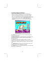
1
This publication, including photographs, illustrations and software, is under the protection of international copyright laws, with all rights reserved. Neither this manual, nor any of the material contained herein, may be reproduced without the express written consent of the manufacturer. The information in this document is subject to change without notice. The manufacturer makes no representations or warranties with respect to the contents hereof and specifically disclaims any implied warranties of merchantability or fitness for any particular purpose. Further, the manufacturer reserves the right to revise this publication and to make changes from time to time in the content hereof without obligation of the manufacturer to notify any person of such revision or changes. Trademarks IBM, VGA, and PS/2 are registered trademarks of International Business Machines. AMD, Athlon XP, Sempron, Athlon and Duron are registered trademarks of Advanced Micro Devices Inc. Microsoft, MS-DOS and Windows 98/ME/NT/2000/XP are registered trademarks of Microsoft Corporation. AMI is a registered trademark of American Megatrends Inc. Other names used in this publication may be trademarks and are acknowledged. Copyright © 2004 All Rights Reserved M863AG/G Series, V1.5D S741/November 2004 Table of Contents Trademark ..................................................................................... I Static Electricity Precautions.................................................III Pre-Installation Inspection.....................................................III Features & Checklist Translations .............................................V Chapter 1: Introduction................................................................1 Key Features............................................................................2 Package Contents ....................................................................5 Chapter 2: Motherboard Installation ..........................................6 Motherboard Components .......................................................7 I/O Ports ..................................................................................7 Installing the Processor............................................................8 Installing Memory Modules ....................................................9 Jumper Settings .....................................................................11 Install the Motherboard .........................................................11 Connecting Optional Devices................................................12 Install Other Devices .............................................................15 Expansion Slots ....................................................................16 Chapter 3: BIOS Setup Utility ...................................................18 Introduction ...........................................................................18 Running the Setup Utility........... …………………………...19 Standard CMOS Setup Page..................................................20 Advanced Setup Page ............................................................21 Features Setup Page...............................................................22 Power Management Setup Page ............................................23 PCI/Plug and Play Setup Page...............................................25 BIOS Security Features Setup Page ......................................25 CPU PnP Setup Page .............................................................26 Hardware Monitor Page ........................................................27 Load Optimal Defaults ..........................................................27 Save Changes and Exit ..........................................................27 Discard Changes and Exit .....................................................28 Chapter 4: Software & Applications .........................................29 Introduction ...........................................................................29 Installing Support Software...................................................30 Bundled Software Installation ...............................................32 II Static Electricity Precautions Static electricity could damage components on this motherboard. Take the following precautions while unpacking this motherboard and installing it in a system. 1. Don’t take this motherboard and components out of their original static-proof package until you are ready to install them. 2. While installing, please wear a grounded wrist strap if possible. If you don’t have a wrist strap, discharge static electricity by touching the bare metal of the system chassis. 3. Carefully hold this motherboard by its edges. Do not touch those components unless it is absolutely necessary. Put this motherboard on the top of static-protection package with component side facing up while installing. Pre-Installation Inspection 1. Inspect this motherboard whether there are any damages to components and connectors on the board. 2. If you suspect this motherboard has been damaged, do not connect power to the system. Contact your motherboard vendor about those damages. III Notice: 1. Owing to Microsoft’s certifying schedule is various to every supplier, we might have some drivers not certified yet by Microsoft. Therefore, it might happen under Windows XP that a dialogue box (shown as below) pop out warning you this software has not passed Windows Logo testing to verify its compatibility with Windows XP. Please rest assured that our RD department has already tested and verified these drivers. Just click the “Continue Anyway” button and go ahead the installation. 2. USB 2.0 Driver Limitations: 2-1 The USB 2.0 driver only supports Windows XP and Windows 2000. 2-2 If you connect a USB 2.0 hub to the root hub, plugging USB devices into this hub, the system might not successfully execute certain USB devices’ connection because it could not recognize these devices. Currently, we are working on such limitations’ solution. As soon as the solution is done, the updated USB drive will be released to our website: www.pcchips.com.tw for your downloading. IV Features and Checklist Translations Liste de contrôle Le coffret de votre carte mère contient les éléments suivants : La carte mère Le Manuel utilisateur Un câble plat pour lecteur de disquette (optionnel) Une câble plat pour lecteur IDE CD de support de logiciels Caractéristiques Processeur Chipset Support de Mémoire AC’97 Audio Codec Prise en charge du Processeur Socket-462 • Supporte le CPU AMD Athlon XP/Sempron/Athlon/Duron • Supporte un Bus Avant allant jusqu’à 400 MHz (M863AG)/ 333 MHz (M863G) Ce chipset comporte SiS741/SiS 741GX Northbridge et SiS963L Southbridge conformément à une architecture novatrice et dimensionnable avec une fiabilité et des performances prouvées. Cette série de carte mères a deux modèles M863AG et M863G : Model Northbridge Southbridge Function M863AG SiS 741 CPU FSB: 400MHz 963L DDR400 M863G SiS 741 GX 963L CPU FSB: 333MHz DDR333/266 • Supporte les CPU AMD Athlon XP, Sempron, Athlon et Duron CPU avec FSB jusqu’à 400(SiS741 NB seulement) /333MHz, et Temporisation Hôte vers DRAM Synchrone/ Quasi-synchrone • Supporte le 400(SiS741 NB seulement)/333/266 SDRAM DDR et contrôleur de mémoire unifiée de haute performance optimisant l’utilisation du bus DRAM • Supporte l’Interface AGP 8X/4X avec Fast Write Transaction • Moteur 3D 256 bits de haute performance et Moteur d'installation en triangle VLIW au format de virgule flottante en 32 bits intégré • Le lien Multiprocessus E/S intégré assure l’accès simultané de transfert de données en amont/aval avec une bande passante de 1.2Go/s. • Conforme aux spécifications PCI 2.2 • Maîtrise de lien Multiprocessus E/S intégré • Maîtrise de Liaison d’E/S Multiprocessus avec transaction Simultanée de Lecture/Ecriture • La carte mère peut recevoir deux sockets DIMM DDR 2.5V de 184 broches d’une capacité totale de mémoire système de 2 Go. • Supporte le bus mémoire DDR 400 (SiS741 NB seulement)/333/266 • Conforme aux spécifications AC’97 2.2 • Conformité de Protocole de Liaison AC • Codec Full-duplex avec vitesse d’échantillonnage indépendante et variable • Tampon d’écouteur intégré • SNR 90db • Sortie Stéréo et Sortie Mono • 4Ch DAC • Coffret 48 LQFP et Coffret TSSOP 24 Brins V Logements d’Extension IDE Interne Ports E/S Internes Fast Ethernet LAN (optional) USB 2.0 • • • • • • • Conforme aux exigences PC99 de Microsoft Support de gestion d’alimentation avancée Deux slots PCI 32 bits Un logement 8X AGP Un logement CNR (Communications and Networking Riser) Deux Connecteurs IDE Prend en Charge les modes PIO (Entrée/Sortie Programmable) et DMA (Accès Direct à la Mémoire) • Supporte maîtrise de bus Ultra DMA IDE avec vitesse de transfert de 133/100/66 Mo/sec La carte mère possède un jeu complet de ports d’E/S et de connecteurs: • Deux ports PS/2 pour souris et clavier • Un port série • Un port parallèle • Un port VGA • ports USB2.0 (quatre ports fond de panier, prises USB internes offrant deux ports supplémentaires • Six ports USB 2.0 (quatre ports fond de panier, connecteurs USB internes offrant deux ports supplémentaires) • Prises audio pour microphone, ligne d’entrée et ligne de sortie • Supporte le fonctionnement en 10/100Mbps et le fonctionnement en half/full duplex • Conforme IEEE 802.3/802.3u • Supporte l’auto négociation IEEE 802.3u clause 28 • Supporte le fonctionnement en mode d’Economie d’Energie d’Interruption de Liaison • Supporte la compensation de Déviation de Ligne de Base (BLW) • Egalisation spéculative • Conforme aux Spécifications de Bus Série Universel Révision 2.0 • Conforme aux Spécifications d’interface de Contrôleur d’Hôte Amélioré de Intel Révision 0.95 • Conforme aux Spécifications d’Interface de Contrôleur d’Hôte Universel Révision 1.1 • Le périphérique multifonction PCI consiste en deux noyaux de Contrôleur d’Hôtes UHCI pour signalisation pleine/faible vitesse et un noyau de Contrôleur d’Hôtes EHCI pour signalisation haute vitesse • Le hub racine consiste en 4 ports de face en aval avec émetteurs-récepteurs de couche physique intégrés partagés par le Contrôleur d’Hôte UHCI et EHCI • Support des Spécifications d’Interface de Gestion d’Alimentation de Bus PCI version 1.1 • Support hérité pour tous les ports face à l’aval. Certaines spécifications matérielles et éléments de logiciels peuvent être modifiés sans avertissement. VI Checkliste Die Verpackung Ihres Motherboards enthält folgende Teile: Motherboard Handbuch Bandkabel für Floppylaufwerke (optional) Bandkabel für IDE-Laufwerke Software-CD Ausstattung Prozessor Chipsatz Speicherunte rstützung AC’97 Audio Codec Unterstütz Socket-462-Prozessoren •Unterstützung für AMD Athlon XP/Sempron/Athlon/Duron prozessors •Unterstützung von bis zu 400 MHz Front-Side Bus (M863AG)/ 333 MHz (M863G) Dieser Chipsatz besteht aus einer SiS741/SiS 741GX Northbridge und einer SiS963L Southbridge. Die Chipsatzarchitektur ist in einem innovativen und skalierbaren Design gehalten und verspricht sowohl Zuverlässigkeit als auch Leistungsstärke. Diese Motherboardserie besteht aus zwei Modellen, M863AG und M863G: Model Northbridge Southbridge Function M863AG SiS 741 CPU FSB: 400MHz 963L DDR400 M863G SiS 741 GX 963L CPU FSB: 333MHz DDR333/266 • Unterstützt AMD Athlon XP, Sempron, Athlon und Duron CPU mit FSB bis zu 400(nur für SiS741 NB)/333MHz, und synchrones/quasisynchrones Host-to-DRAM Timing • Unterstützt 400(nur für SiS741 NB)/333/266 SDRAM DDR und High Performance Unified Memory Controller zur Optimierung der DRAM BusNutzung. • Unterstützt AGP 8X/4X-Interface mit Fast Write-Abwicklung • Eingebauter 256-Bit 3D Hochleistungsmotor und VLIW Dreieck-Startmotor mit 32-BitFlußpunktformat • Integriertes mehrfasiges I/O Bindeglied, welches den Zulauf der Datenübertragung stromaufwärts und stromabwärts mit einer 1.2GB/SekBandbreite sicherstellt • Entspricht PCI 2.2 Spezifikation • Eingebautes Multithreaded I/O-Link-Mastering • Multithread I/O Link Mastering mit parallelem Read/Write-Betrieb • Das Motherboard umfaßt zwei 184-polige, 2.5V-DDR-Steckplätze für insgesamt 2 GB Speicher. • Unterstützung für DDR bis zu 400(nur für SiS741 NB)/333/266 Speicherbus • Entspricht AC’97 2.2 • Entspricht AC-Link Protokoll • Vollduplex Codec mit unabhängiger und variabler Abtastrate • Eingebauter Kopfhörerpuffer • SNR 90db • Stereo- und Monoausgang • 4Ch DAC • 48 LQFP Package und 24-Lead TSSOP Package VII Erweiterungs steckplätze Onboard IDE Onboard I/O Ports Fast Ethernet LAN (optional) USB 2.0 • • • • • • • Entspricht Microsofts PC99-Spezifikationen Unterstützung für Advanced Power Management Zwei 32-Bit PCI-Steckplätze Ein 8X AGP-Steckplatz Ein CNR-Steckplatz (Communications & Networking Riser) Zwei IDE-Header Unterstützt die Modi PIO (Programmable Input/Output) und DMA (Direct Memory Access) • Unterstützung für IDE Ultra DMA-Busmastering mit Transferraten von 133 100/66 MB/Sek Das Motherboard verfügt über einen kompletten Satz von I/O-Schnittstellen und Anschlüssen: • Zwei PS/2-Steckplätze für Maus und Tastatur yboard • Ein serieller Steckplatz • Ein paralleler Steckplatz • Ein VGA Steckplatz • Sechs USB2.0-Ports (vier Ports auf der Rückseite; die Onboard-USBHeader für zwei zusätzliche Ports). • Audioanschlüsse für Mikrofon, line-in und line-out • Unterstützt 10/100Mbps-Betrieb und halben/vollen Duplex-Betrieb • Übereinstimmend mit IEEE 802.3/802.3u • Unterstützt IEEE 802.3u Klausel 28 Selbstentscheidung • Unterstützt den Betrieb unter dem Modus “Link Down Power Saving” (Verbundener Sparbetrieb) • Unterstützt Base Line Winder (BLW) - Ausgleich • Anpassungsfähige Ausgleichung • Entspricht Universal Serial Bus-Spezifikation, Revision 2.0 • Entspricht Intels Enhanced Host Controller Interface-Spezifikation, Revision 0.95 • Entspricht Universal Host Controller Interface -Spezifikation Revision 1.1 • PCI-Multifunktionsgerät besteht aus zwei UHCI Host Controller-Kernen für Signalübertragung bei voller und niedriger Geschwindigkeit sowie einem EHCI Host Controller-Kern für Hochgeschwindigkeits- Signalübertragung • Root Hub besteht aus 4 Downstream-Ports mit integrierten Physical LayerÜberträgern für gemeinsame Nutzung durch UHCI und EHCI Host Controller • Unterstützt PCI-Bus Power Management Interface , Spezifikation Release 1.1 • Legacy-Unterstützung für alle Downstream-Ports Bestimmte Hardwarespezifikationen und Teile der Softwareausstattung können ohne weitere Ankündigung abgeändert werden. VIII Lista L’imballo della scheda madre é composto da: La scheda madre Il manuale Una piattina per il collegamento dei drive (opzionale) Una piattina IDE Il CD con il Software di supporto Caratteristiche Processor Chipset Memory Support AC’97 Audio Codec Slot di espansione Dotata di Socket 462 per Processori • Supporta CPU AMD Athlon XP/Sempron/ Athlon/Duron • Supporta fino a 400 MHz (M863AG)/ 333 MHz (M863G) Front Side Bus In accordo ad una archittettura scabile e innovative sono presenti nel chipset il Northbridge SiS741/SiS 741GX e Southbridge SiS963L. Di questa scheda madre sono stati sviluppati due modelli: M863AG e M863G: Model Northbridge Southbridge Function M863AG SiS 741 CPU FSB: 400MHz 963L DDR400 M863G SiS 741 GX 963L CPU FSB: 333MHz DDR333/266 • Vengono supportate le CPU AMD Athlon XP, Sempron, Athlon e Duron con FSB fino a 400 (solo SiS741 NB)/333MHz e Timing Sincrono/ Quasisincrono Host-to-DRAM. • Supporto 400(solo SiS741 NB)/333/266 SDRAM DDR ed é presente un controller ad alte prestazioni in grado di ottimizzare l’utilizzazione del bus DRAM • Supporto dell’interfaccia AGP 8X/4X con Fast Write Transaction • Motore 3D a 256 bit con floating point VLIW triangle a 32 bit • Link I/O Multi-threaded integrato assicura la concorrenza dei trasferimenti upstream/downstream con una larghezza di banda pari a 1.2GB/s • Compatibile con le specifiche PCI 2.2 • Link mastering I/O multi-threaded integrato • I/O con Link Mastering Multithread con possibilità di transazione concorrente Read/Write • La scheda madre è dotata di 2 socket DIMM DDR 184 pin, 2.5V per una capacità totale di memoria di sistema pari a 2 GB. • Supporta bus di memoria DDR 400 (solo SiS741 NB)/333/266 • Conforme con le specifiche AC`97 2.2 • Conforme al Protocollo AC-Link • Codec Full-duplex con campionamento indipendente e variabile • Buffer Cuffie Interno • SNR 90db • Output Stereo e Mono Out • 4Ch DAC • Package 48 LQFP e TSSOP 24 Lead • Supporto degli standard Microsoft PC99 • Supporto per gestione energetica avanzata • Due slot a 32-bit PCI • Una slot AGP 8X • Uno slot CNR (Communications and Networking Riser) IX Onboard IDE Onboard I/O Ports Fast Ethernet LAN (opzionale) USB 2.0 • Due connettori IDE • Supporto della modalità PIO (Programmable Input/Output) e DMA (Direct Memory Access) • Supporto per le modalità Bus Mastering e Ultra DMA ATA 133/100/66 MB/sec La scheda madre è dotata da una serie completa di porte e connettori I/O: • Due porte PS/2 per tastiera e mouse • Una porta seriale • Una porta parallela • Una porta VGA • Sei porte USB2.0 (Quattro presenti nella parte posteriore, connettori USB integrati nella scheda madre per l’aggiunta di altre 2 porte • Jack audio per microfono, ingresso linea e uscita linea • Operazioni 10/100Mbps e half/full duplex • Conforme allo standard IEEE 802.3/802.3u • Negoziazione automatica 28 clause IEEE 802.3u • Operazioni nella modalitá “Link Down Power Saving mode” • Supporto compensazione Base Line Winder (BLW) • Adaptive Equalization • Conforme alle specifiche Universal Serial Bus 2.0 • Conforme alle specifiche Intel Enhanced Host Controller revisione 0.95 • Conforme alle specifiche Universal Host Controller Interface revisione 1.1 • Il dispositivo PCI multifunzione consiste di due schede di controllo UHCI per la trasmissione segnali pieno/basso e una scheda di controllo EHCI per la trasmissione segnali ad alta velocità. • Il porto hub di base consiste di 4 porte downstream con ricetrasmittenti integrati nel layer fisico condivisi dalla scheda di controllo interfaccia UHCI e EHCI • Supporto per interfaccia risparmio energia bus PCI specifiche release 1.1 • Supporto per tutte le porte downstream precedenti Alcune specifiche hardware ed elementi software sono soggetti a variazioni senza preavviso. X LiSTA DE VERIFICACIÓN El paquete de su placa principal contiene los sigtes. ítems: La placa principal El Manual del Usuario Un cable cinta para el lector de disquete (optativo) Un cable cinta para el lector IDE CD de Software de soporte Características Processor Chipset Soporte de Memoria AC’97 Audio Codec Soporte de Procesador Socket-462 • Soporta CPU de AMD Athlon XP/ Sempron/ Athlon/Duron • Soporta hasta Bus de Lado Frontal de 400 MHz (M863AG)/ 333 MHz (M863G) Hay SiS741/SiS 741GX Northbridge y SiS963L Southbridge en este chipset en confomidad con una arquitectura innovadora y escalable con fiabilidad y rendimiento comprobados. La serie de esta placa principal tiene dos modelos, M863AG y M863G: Model Northbridge Southbridge Function M863AG SiS 741 CPU FSB: 400MHz 963L DDR400 M863G SiS 741 GX 963L CPU FSB: 333MHz DDR333/266 • Soporta las CPUs AMD Athlon XP, Sempron, Athlon y Duron con FSB hasta 400(SiS741 NB solamente)/333 MHz, y Cronometraje de Anfitrión a DRMA Sincrónico/ Casi-sincrónico • Soporta 400(SiS741 NB solamente)/333/266 SDRAM DDR y controlador de memoria unificado de alto rendimiento que optimiza la utilización de bus DRAM • Soporta Interfaz AGP 8X/4X con Transacción de Escritura Rápida • Motor 3D de 156-bit de alto rendimiento incorporado y motor de setup de triángulo VLIW de formato de punto flotante de 32-bit • Vínculo I/O multihilado integrado asegura la concurrencia de la transferencia de datos hacia arriba y abajo con un ancho de banda de 1.2GB/s • Especificación de conformidad PCI 2.2 • Entrada/Salida multi-ensartada integrada y enlace maestro • Mastering de vínculo I/O multihilado con transacción Concurrente de Lectura/Escritura • La placa principal acomoda dos 2.5V DDR de 184 pines, enchufes DIMM con una capacidad total de 2GB de memoria de sistema. • Soporta DDR hasta bus de memoria de 400 (solamente SiS741 NB)/333/266 • Conforme con la especificación AC’97 2.2 • Conformidad de Protocolo AC-Link • Codec de Full-duplex con índice de muestreo independiente y variable • Buffer de Audífono Incorporado • SNR 90db • Salidas de Estéreo y Modo • 4Ch DAC • Paquetes 48 LQFP y 24-Lead TSSOP • Satisface los requisitos PC99 de Microsoft XI Ranuras de Expansión IDE Abordos Puertos I/O Abordos Ethernet LAN Rápido (optional) USB 2.0 • • • • • • Soporte de administración de energía avanzada Dos ranuras 32-bit PCI Una ranura 8X AGP Una ranura CNR (Communications and Networking Riser)t Dos conectores IDE Soporta modos PIO (Entrada/Salida Programable/Programmable Input/Output) y modos DMA (Acceso de Memoria Directo/Direct Memory Access). • Soporta mastering de bus IDE Ultra DMA con índices de transferencia de 133/100/66 /MB/sec La placa principal tiene un juego completo de puertos I/O y conectores: • Dos puertos PS/2 para ratón y teclado • Un puerto serial • Un puerto paralelo • Un puerto VGA • Seis puertos USB 2.0 (cuatro puertos de panel trasero, cabezales USB abordos que proveen dos puertos extras) • Clavijas de sonido para micrófono, entrada y salida de línea • Soporta operación 10/100Mbps y operación de duplex medio/completo. • Conformidad IEEE 802.3/802.3u • Soporta auto-negociación IEEE 802.3u cláusula 28 • Soporta operación bajo el modo Link Down Power Saving (Vincular Ahorro de Suministro) • Soporta compensación Base Line Winder (BLW) • Ecualización Adaptiva. • Conforme con la Especificación de Bus Serial Universal Revisión 2.0 • Conforme con Controlador Anfitrión Reforzado de Intel Interface Specification Revision 0.95 • Conforme con la Especificación de Interfaz de Controlador Anfitrión Universal Revisión 1.1 • Dispositivo PCI multi-función se consiste de dos centros de Controlador Anfitrión UHCI para señalización de velocidad completa/baja y un centro de Controlador Anfitrión EHCI para señalización de alta velocidaa • Root hub consiste de 4 puertos que miran hacia abajo con transceptores de capa física integrado compartido por Controlador Anfitrión UHCI y EHCI • Soporta Especificación de Interfaz de Administración de Energía de BUS PCI versión 1.1 • Soporte de legado para todos los puetos que miran hacia abajo Algunas especificaciones de hardware e ítems de software son sujetos a cambio sin aviso previo . XII Lista de verificação A embalagem da sua placa principal contém os seguintes itens: A placa principal O Manual do Utilizador Um cabo para a unidade de disquetes (opcional) Um cabo para a unidade IDE CD de suporte para o software Características Processador Chipset Suporte de memória AC’97 Audio Codec Slots de expansão Suporte do Processador Socket-462 • Suporta AMD Athlon XP/Sempron/Athlon/Duron processadors • Suporta até 400 MHz ( M863AG)/ 333 MHz ( M863G) Front-Side Conta com SiS741/SiS 741GX Northbridge e SiS963L Southbridge neste chipset, de acordo com uma arquitectura inovadora e escalável com um nível de confiança e desempenho comprovado. Esta série de placa mãe possui dois modelos, M863AG e M863G: Model Northbridge Southbridge Function M863AG SiS 741 CPU FSB: 400MHz 963L DDR400 M863G SiS 741 GX 963L CPU FSB: 333MHz DDR333/266 • Suporta AMD Athlon XP, Sempron, Athlon, Duron CPU com FSB até 400(apenas para SiS741 NB)/333 MHz, e Síncrono / Quasi-síncrono Hostpara-DRAM Timing • Suporta 400(apenas para SiS741 NB)/333/266 SDRAM DDR e controlador de memória unificada de alta perfomrance optimizando o uso do DRAM bus • Suporta Interface c/ Transação de Escrita Rápida AGP 8X/4X • Engenho de alta performance embutido de 256-bit 3D e formato de ponto flutuante de 32-bit engenho de configuração triangular VLIW • Linque I/O Multi-entrelaçado assegurando a concurrência de correntes de transferência de dados para cima/para baixo com banda de 1.2GB/s • Especificação PCI 2.2 Compatível • Linque mestre multi-entrelaçado I/O • I/O link Mastering Interlaceado com transação Concurrente Read/Write • A placa mãe acomoda dois pinos DDR 184, soquetes 2.5V DIMM com uma capacidade total de 2 GB de sistema de memória. • Suporta bus de memória DDR 400(apenas para SiS741 NB)/333/266 memory bus • Compatível com a especificação AC’97 2.2 • AC-Link Protocolo compatível • Full-duplex Codec com taxa de amostra variável e independente • Registrador de Fone de Ouvido Embutido • SNR 90db • Stereo Output e Mono Out • 4Ch DAC • Pacote 48 LQFP e 24-Lead TSSOP • De acordo com os requerimentos da Microsoft PC99 • Suporte de gerenciamento de força avançado • Dois encaixes 32-bit PCI slots • Um slot AGP 8X XIII IDE na placa Portas I/O na placa Fast Ethernet LAN (optional) USB 2.0 • Um encaixe para CNR (Communications and Networking Riser) • Dois conectores IDE • Suporta modos PIO (Input/Output Programável) e DMA (Direct Memory Access) • Suporta IDE Ultra DMA bus mastering com razão de transferência de 133/100/66 MB/sec A placa principal possui um conjunto completo de portas e conectores I/O: • Duas portas PS/2 para o rato e teclado • Uma porta série • Uma porta paralela • Uma porta VGA • Seis portes USB2.0 (quatro portes traseiros, um conector USB na placa com dois portes extras) • Jacks audio para microfone, line-in e line-out • Suporta operação 10/100Mbps e operação parcial/completa duplex • IEEE 802.3/802.3u complacente • Suporta IEEE 802.3u cláusula 28 auto negociação • Suporta operação sob o modo Link Down Power Saving • Suporta compensação Base Line Winder (BLW) • Equalização Adaptativa • Compatível com Universal Serial Bus Revisão 2.0 da especificação • Compatível com controlador Enhanced Host da Intel Revisão 0.95 da especificação da interface • Compatível com controlador Universal Host Revisão 1.1 da especificação da Interface • O dispositivo PCI muli-funções consiste em dois núcleos de Controlador UHCI Host Controller para sinalização de velocidade total/baixa em um núcleo de Controlador EHCI Host para sinalização de alta velocidade • O núcleo de raiz consiste em 4 portas de protecção a jusante com transreceptores de camadas físicas integrados partilhados pelos controladores Host UHCI e EHCI • Suporte de gestão de energia PCI-Bus Revisão 1.1 da especificação da interface • Suporte para todas as portas de protecção a jusante As especificações de alguns artigos de hardware e software encontram-se sujeitos a alterações sem aviso prévio. XIV 检查单 您的主板包装含有以下项目: 主板 用户手册 一根磁盘驱动器扁平电缆(可选) 一根 IDE 驱动器扁平电缆 软件支持CD 功能 处理器 支持 Socket-462 处理器 • 支持 AMD Athlon XP/Sempron/Athlon/Duron CPU • 支持400 MHz (M863AG)/ 333 MHz (M863G) 前端总线 芯片组 芯片组包含SiS741/SiS 741GX北桥 和SiS963L南桥,它基于一种新型的、可扩展的架构,能提供已经证明的可靠 性和高性能。此主板系列有两种型号,M863AG 和 M863G: Model Northbridge Southbridge Function M863AG SiS 741 CPU FSB: 400MHz 963L DDR400 M863G SiS 741 GX 963L CPU FSB: 333MHz DDR333/266 • 支持最高 FSB 为400 (只支持SiS741 NB) /333MHz 的 AMD Athlon XP, Sempron, Athlon 和 Duron CPU, 支持同步/准同步主机到 DRAM 定时 • 支持400 (只支持SiS741 NB)/333/266 DDR SDRAM和对 DRAM 总线利用率进行优化的高性能标准存储控制器 • 支持带有 Fast Write Transaction 的 AGP 8X/4X 接口 • 内建高性能 256 位 3D 引擎和 32 位浮点式 VLIW 三角设置引擎 • 集成多线程 I/O 连接,确保 1.2GB/s 带宽的并发上行/下行数据传输 • 符合 PCI 2.2 规格 • 集成多线程 I/O 连接 • 带读/写并发处理的多线程 I/O 连接主控 内存支持 • 此主板支持 2 条 DDR(184 pin, 2.5V)DIMM 内存,内存最大可支持到 2 GB。 • 支持 DDR 400 (只支持SiS741 NB)/333/266 存储总线 AC’97 • 兼容 AC’97 2,2 规格 编解码器Code • 符合 AC-Link 协议 c • 具有独立和可调采样速率的全双工编解码器 XV • 内建耳机缓冲 • SNR 90db • 立体声输出和单声道输出 • 4 通道 DAC • 48 LQFP Package 和 24-Lead TSSOP Package • 符合 Microsoft PC99 标准 • 支持高级电源管理 扩展槽 • 2个 32 位 PCI 扩展插槽 • 1 个 8X AGP 插槽 • 一个通信网络转接 (CNR) 插槽 Onboard IDE • 2 个 IDE 接口 • 支持 PIO (程控输入/输出) 和 DMA (直接存储器存取) 模式 • 支持 IDE Ultra DMA 总线控制,传输速率可达133/100/66 MB/sec 集成 I/O 此主板具有完整的 I/O 端口和插孔: 端口 • 2 个用于鼠标和键盘的 PS/2 端口 • 1 个串口 • 1 个并口 • 1 个 VGA 端口 • 6 个 USB2.0 端口(主板后面板带 4 个接口,板上 USB 接口提供其它 2 个端口) • 麦克风、线入和线出声音插孔 Fast Ethernet LAN (optional) • 支持10/100Mbps 工作和半/全双工工作 • 符合 IEEE 802.3/802.3u 标准 • 支持IEEE 802.3u 第 28 项的自协商 • 支持链路故障节电模式下操作 • 支持基线漂移 (BLW) 补偿 • 自适应均衡 USB 2.0 • 符合通用串行总线规格 2.0 版本 • 符合 Intel 0.95 版本的增强主控器接口规格 • 符合 1.1 版本的通用主控器接口规格 • PCI 多功能设备由 2 个用于全速/低速传输数据的 UHCI 主控器 和1个用于高速传输数据的EHCI主控器组成 • Root集线器包括4个下行端口,带有与UHCI和EHCI 主控制器共用的集成物理层收发器。 • 支持 1.1版本的 PCI 总线电源管理接口规格支持 XVI • 所有传统下行端口 部分硬件规格和软件项目若有更改恕不另行通知。 XVII Chapter 1 Introduction This motherboard has a Socket-A support for the AMD Athlon XP/Sempron/Athlon/Duron processors. The Socket-A processor’s front-side bus speed is 400 MHz (for M863AG)/ 333 MHz (for M863G). This motherboard has the SiS741/SiS 741GX Northbridge and SiS963L Southbridge that supports the AC’ 97 audio codec, the Ultra DMA 133/100/66 function, and the built-in USB 2.0 providing higher bandwidth. It implements Universal Serial Bus Specification Revision 2.0 and is compliant with UHCI 1.1 and EHCI 0.95. It has two 32-bit PCI slots, one 8X AGP slot, one CNR (Communications and Networking Riser) slot, and supports the onboard 10BaseT/100BaseTX Network interface (optional). In addition, this motherboard has a full set of I/O ports including two PS/2 ports for mouse and keyboard, one serial port, one VGA port, one parallel port and maximum six USB2.0 ports– four back-panel ports and one onboard USB connector USB2 providing two extra ports by connecting the Extended USB Module to the motherboard. This motherboard is a Micro ATX size motherboard and has power connectors for an ATX power supply. Note: M863AG with SiS741NB and SiS963L SB supports FSB 400MHz and DDR400; M863G with SiS741 GX NB and SiS963L SB, FSB333MHz and DDR333/266. Key Features This motherboard has these key features: Socket-A Processor Support ♦ Supports AMD Athlon XP/Sempron/Athlon/Duron processors ♦ Supports Front-Side Bus 400 MHz (for M863AG)/ 333 MHz (for M863G) Chipset There are SiS741/SiS 741GX Northbridge and SiS963L Southbridge in this chipset in accordance with an innovative and scalable architecture with proven reliability and performance. This motherboard series has two models, M863AG and M863G: Model M863AG Northbridge SiS 741 Southbridge 963L M863G SiS 741 GX 963L Function CPU FSB: 400MHz DDR400 CPU FSB: 333MHz DDR333/266 ♦ Supports AMD Athlon XP/Sempron/Athlon/Duron CPU with FSB up to 400(only for SiS741 NB)/333 MHz, and Synchronous/ Quasi-synchronous Host-to-DRAM Timing ♦ Supports 400(only for SiS741 NB)/333/266 DDR SDRAM and high performance unified memory controller optimizing the DRAM bus utilization ♦ Supports AGP 8X/4X Interface w/ Fast Write Transaction ♦ Built-in a high performance 256-bit 3D engine and 32-bit floating point format VLIW triangle setup engine ♦ Integrated Multi-threaded I/O link ensures concurrency of upstream/down stream data transfer with 1.2GB/s bandwidth ♦ PCI 2.2 Specification Compliance ♦ Integrated Multithreaded IO Link Mastering ♦ Multithread I/O link Mastering with Read/Write Concurrent transaction 2 Memory Support ♦ The motherboard accommodates 2 DDR 184 pin, 2.5V DIMM sockets with a total capacity of 2 GB system memory. ♦ Supports DDR 400(only for SiS741 NB)/333/266 memory bus AC’97 Audio Codec ♦ Compliant with AC’97 2.2 specification ♦ AC-Link Protocol compliance ♦ Full-duplex Codec with independent and variable sampling rate ♦ Earphone Buffer Built-In ♦ SNR 90db ♦ Stereo Output and Mono Out ♦ 4Ch DAC ♦ 48 LQFP Package and 24-Lead TSSOP Package ♦ Meet Microsoft’s PC99 requirements ♦ Advanced power management support Expansion Options The motherboard comes with the following expansion options: ♦ Two 32-bit PCI slots ♦ One 8X AGP slot ♦ One CNR (Communications and Networking Riser) slot Onboard IDE ♦ Two IDE Connectors ♦ Supports PIO (Programmable Input/Output) and DMA (Direct Memory Access) modes ♦ Supports IDE Ultra DMA bus mastering with transfer rates of 133/100/66 MB/sec Onboard I/O Ports The motherboard has a full set of I/O ports and connectors: ♦ Two PS/2 ports for mouse and keyboard ♦ One serial port 3 ♦ One parallel port ♦ One VGA port ♦ Six USB2.0 ports (four back-panel ports, one onboard USB connector USB2 providing two extra ports) ♦ Audio jacks for microphone, line-in and line-out BIOS Firmware This motherboard uses AMI BIOS that enables users to configure many system features including the following: ♦ Power management ♦ Wake-up alarms ♦ CPU parameters and memory timing ♦ CPU and memory timing The firmware can also be used to set parameters for different processor clock speeds. Built-in Ethernet LAN (optional) ♦ Supports 10/100Mbps operation and half/full duplex operation ♦ IEEE 802.3/802.3u compliant ♦ Supports IEEE 802.3u clause 28 auto negotiation ♦ Supports operation under Link Down Power Saving mode ♦ Supports Base Line Winder (BLW) compensation ♦ Adaptive Equalization USB 2.0 ♦ Compliant with Universal Serial Bus Specification Revision 2.0 ♦ Compliant with Intel’s Enhanced Host Controller Interface Specification Revision 0.95 ♦ Compliant with Universal Host Controller Interface Specification Revision 1.1 ♦ PCI multi-function device consists of two UHCI Host Controller cores for full-/low-speed signaling and one EHCI Host Controller core for high-speed signaling ♦ Root hub consists 4 downstream facing ports with integrated physical layer transceivers shared by UHCI and EHCI Host Controller 4 ♦ Support PCI-Bus Power Management Interface Specification release 1.1 ♦ Legacy support for all downstream facing ports Dimensions ♦ Micro ATX form factor of 244 x 200 mm Note: Hardware specifications and software items are subject to change without notification. Package Contents Your motherboard package contains the following items: The motherboard The User’s Manual One diskette drive ribbon cable (optional) One IDE drive ribbon cable The Software support CD Optional Accessories You can purchase the following optional accessories for this motherboard. Extended USB module CNR v.90 56K Fax/Modem card Card Reader Note: You can purchase your own optional accessories from the third party, but please contact your local vendor on any issues of the specification and compatibility. 5 Chapter 2 Motherboard Installation To install this motherboard in a system, please follow these instructions in this chapter: Identify the motherboard components Install a CPU Install one or more system memory modules Make sure all jumpers and switches are set correctly Install this motherboard in a system chassis (case) Connect any extension brackets or cables to connectors on the motherboard Install peripheral devices and make the appropriate connections to connectors on the motherboard Note: 1. Before installing this motherboard, make sure jumper JP2 is under Normal setting. See this chapter for information about locating JP2 and the setting options. 2. Never connect power to the system during installation; otherwise, it may damage the motherboard. Motherboard Components Identify major components on the motherboard via this diagram underneath. I/O Ports The illustration below shows a side view of the built-in I/O ports on the motherboard. (shared with JP1) 7 (optional) PS/2 Mouse PS/2 Keyboard Parallel Port (PRN) COM1 LAN Port (optional) USB Ports Use the upper PS/2 port to connect a PS/2 pointing device. Use the lower PS/2 port to connect a PS/2 keyboard. Use the Parallel port to connect printers or other parallel communications devices. Use the COM port to connect serial devices such as mice or fax/modems. COM1 is identified by the system as COM1. Connect an RJ-45 jack to the LAN port to connect your computer to the Network. Use the USB ports to connect USB devices. Note: The lower USB port located beside the VGA port is shared with the JP1 connector. Audio Ports Use the three audio ports to connect audio devices. The first jack is for stereo Line-In signal. The second jack is for stereo LineOut signal. The third jack is for Microphone. Installing the Processor This motherboard has a Socket 462 processor socket. When choosing a processor, consider the performance requirements of the system. Performance is based on the processor design, the clock speed and system bus frequency of the processor, and the quantity of internal cache memory and external cache memory. CPU Installation Procedure Follow these instructions to install the CPU: 1 CPUFAN1 Pin1 Socket-462 8 1. Unhook the locking lever of the CPU socket. Pull the locking lever away from the socket and raising it to the upright position. 2. Match the pin1 corner marked as the beveled edge on the CPU with the pin1 corner on the socket. Insert the CPU into the socket. Do not use force. 3. Push the locking lever down and hook it under the latch on the edge of socket. 4. Apply thermal grease to the top of the CPU. 5. Install the cooling fan/heatsink unit onto the CPU, and secure them all onto the socket base. 6. Plug the CPU fan power cable into the CPU fan connector (CPUFAN1) on the motherboard. Installing Memory Modules This motherboard accommodates two 184-pin 2.5V unbuffered Double Data Rate SDRAM (DDR SDRAM) Dual Inline Memory Module (DIMM) sockets, and supports up to 2.0 GB of 400/333/266 MHz DDR SDRAM. DDR SDRAM is a type of SDRAM that supports data transfers on both edges of each clock cycle (the rising and falling edges), effectively doubling the memory chip’s data throughput. DDR DIMMs can synchronously work with 166 MHz or 200 MHz memory bus. DDR SDRAM provides 2.1 GB/s, 2.7 GB/s or 3.2GB/s data transfer rate when the bus is 133 MHz, 166 MHz or 200 MHz, respectively. DDR SDRAM uses additional power and ground lines and requires 184-pin 2.5V unbuffered DIMM module. 9 DDR1 DDR2 Memory Module Installation Procedure These modules can be installed with up to 2 GB system memory. Following these steps to install the memory module. 1. Push down the latches on both sides of the DIMM socket. 2. Align the memory module with the socket. There is a notch on the DIMM socket that you can install the DIMM module in the correct direction. Match the cutout on the DIMM module with the notch on the DIMM socket. 3. Install the DIMM module into the socket and press it firmly down until it is seated correctly. The socket latches are levered upwards and latch on to the edges of the DIMM. 4. Install any remaining DIMM modules. 10 Jumper Settings Using a jumper cap to connect two pins is SHORT, removing it from these pins, OPEN. 1 JP2 JP2: Clear CMOS Jumper This jumper is to clear the contents of CMOS memory. You may need to clear the CMOS memory if the settings in the Setup Utility are incorrect that prevents your motherboard from operating. To clear the CMOS memory, disconnect all the power cables from the motherboard and then move the jumper cap into the CLEAR setting for a few seconds. Function Clear CMOS Normal Jumper Setting Short Pins 1-2 Short Pins 2-3 Install the Motherboard Install the motherboard in a system chassis (case). The board is a Micro ATX size motherboard. You can install this motherboard in an ATX case. Make sure your case has an I/O cover plate matching the ports on this motherboard. Install the motherboard in a case. Follow the case manufacturer’s instructions to use the hardware and internal mounting points on the chassis. 11 J1 1 SYSFAN1 U5 1 SW1 Connect the power connector from the power supply to the U5 connector on the motherboard. J1 is the CPU Vcore power connector. If there is a cooling fan installed in the system chassis, connect the cable from the cooling fan to the SYSFAN1 fan power connector on the motherboard. Connect the case switches and indicator LEDs to the SW1 connector. Here is a list of the PANEL1 pin assignments. Pin 1 3 5 7 9 Signal HD_LED_P HD_LED_N RESET_SW_N RESET_SW_P RSVD_DNU Pin 2 4 6 8 10 Signal FP PWR/SLP FP PWR/SLP POWER_SW_P POWER_SW_N KEY Connecting Optional Devices Refer to the following for information on connecting the motherboard’s optional devices: 1 1 JP1 AUDIO1 1 IR1 1 1 USB2 SPK1 12 SPK1: Speaker Connector Connect the cable from the PC speaker to the SPK1 connector on the motherboard. Pin 1 3 Signal SPKR GND Pin 2 4 Signal NC +5V AUDIO1: Front Panel Audio Connector This connector allows the user to install auxiliary front-oriented microphone and line-out ports for easier access. Pin 1 3 5 7 9 Signal AUD_MIC AUD_MIC_BIAS AUD_FPOUT_R HP_ON AUD_FPOUT_L Pin 2 4 6 8 10 Signal AUD_GND AUD_VCC AUD_RET_R KEY AUD_RET_L USB2: Front panel USB Connector The motherboard has USB ports installed on the rear edge I/O port array. Additionally, some computer cases have USB ports at the front of the case. If you have this kind of case, use auxiliary USB connectors USB2/USB3 to connect the front-mounted ports to the motherboard. Pin 1 3 5 7 9 Signal VERG_FP_USBPWR0 USB_FP_P0USB_FP_P0+ GROUND KEY Pin 2 4 6 8 10 Signal VERG_FP_USBPWR0 USB_FP_P1USB_FP_P1+ GROUND USB_FP_OC0 1. Locate the USB2 connector on the motherboard. 2. Plug the bracket cable onto the USB2 connector. 3. Remove a slot cover from one of the expansion slots on the system chassis. Install an extension bracket in the opening. Secure the extension bracket to the chassis with a screw. JP1: USB Card Reader Connector (optional) This connector is for connecting internal USB card reader. You can use a card reader to read or transfer files and digital images to your computer. 13 Pin 1 3 5 Signal Vcc5V USB+ KEY Pin 2 4 Signal USBGND The JP1 is shared with the lower USB port located beside the VGA port of the I/O back panel. Please see “I/O Ports” for more information. Please check the pin assignment of the cable and the USB header on the motherboard. Make sure the pin assignment will match before plugging in. Any incorrect usage may cause unexpected damage to the system. The vendor won’t be responsible for any incidental or consequential damage arising from the usage or misusage of the purchased product. IR1: Infrared Port The infrared port allows the wireless exchange of information between your computer and similarly equipped devices such as printers, laptops, Personal Digital Assistants (PDAs), and other computers. Pin 1 3 5 Signal NC +5V IRTX Pin 2 4 6 Signal KEY GND IRRX 1. Locate the infrared port IR1 connector on the motherboard. 2. If you are adding an infrared port, connect the ribbon cable from the port to the IR1 connector and then secure the port to an appropriate place in your system chassis. 14 Install Other Devices Install and connect any other devices in the system following the steps below. 1 FDC1 IDE1 IDE2 1 1 Floppy Disk Drive The motherboard ships with a floppy disk drive cable that can support one or two drives. Drives can be 3.5” or 5.25” wide, with capacities of 360K, 720K, 1.2MB, 1.44MB, or 2.88MB. Install your drives and connect power from the system power supply. Use the cable provided to connect the drives to the floppy disk drive connector FDC1. IDE Devices IDE devices include hard disk drives, high-density diskette drives, and CD-ROM or DVD-ROM drives, among others. The motherboard ships with an IDE cable that can support one or two IDE devices. If you connect two devices to a single cable, you must configure one of the drives as Master and one of the drives as Slave. The documentation of the IDE device will tell you how to configure the device as a Master or Slave device. The Master device connects to the end of the cable. Install the device(s) and connect power from the system power supply. Use the cable provided to connect the device(s) to the Primary IDE channel connector IDE1 on the motherboard. If you want to install more IDE devices, you can purchase a second IDE cable and connect one or two devices to the Secondary IDE 15 channel connector IDE2 on the motherboard. If you have two devices on the cable, one must be Master and one must be Slave. Internal Sound Connections If you have installed a CD-ROM drive or DVD-ROM drive, you can connect the drive audio cable to the onboard sound system. CD1 1 When you first start up your system, the BIOS should automatically detect your CD-ROM/DVD drive. If it doesn’t, enter the Setup Utility and configure the CD-ROM/DVD drive that you have installed. On the motherboard, locate the 4-pin connector CD1. CD1 Pin 1 2 3 4 Signal CD IN L GND GND CD IN R Expansion Slots This motherboard has one AGP, one CNR and two 32-bit PCI slots. 16 AGP1 CNR1 PCI2 PCI1 Follow the steps below to install an AGP/CNR/PCI expansion card. 1. Locate the AGP, CNR or PCI slots on the motherboard. 2. Remove the blanking plate of the slot from the system chassis. 3. Install the edge connector of the expansion card into the slot. Ensure the edge connector is correctly seated in the slot. 4. Secure the metal bracket of the card to the system chassis with a screw. 8X AGP Slot You can install a graphics adapter that supports the 8X AGP specification and has an 8X AGP edge connector in the AGP slot. CNR Slot You can install the CNR (Communications and Networking Riser) cards in this slot, including LAN, Modem, and Audio functions. PCI Slots You can install the 32-bit PCI interface expansion cards in the slots. 17 Chapter 3 BIOS Setup Utility Introduction The BIOS Setup Utility records settings and information of your computer, such as date and time, the type of hardware installed, and various configuration settings. Your computer applies those information to initialize all the components when booting up and basic functions of coordination between system components. If the Setup Utility configuration is incorrect, it may cause the system to malfunction. It can even stop your computer booting properly. If it happens, you can use the clear CMOS jumper to clear the CMOS memory which has stored the configuration information; or you can hold down the Page Up key while rebooting your computer. Holding down the Page Up key also clears the setup information. You can run the setup utility and manually change the configuration. You might need to do this to configure some hardware installed in or connected to the motherboard, such as the CPU, system memory, disk drives, etc. Running the Setup Utility Every time you start your computer, a message appears on the screen before the operating system loading that prompts you to “Hit <DEL>if you want to run SETUP”. Whenever you see this message, press the Delete key, and the Main menu page of the Setup Utility appears on your monitor. CMOS SETUP UTILITY – Copyright (C) 1985-2003, American Megatrends, Inc. Standard CMOS Setup Advanced Setup Features Setup Power Management Setup PCI / Plug and Play Setup BIOS Security Features CPU PnP Setup Hardware Monitor Load Optimal Defaults Save Changes and Exit Discard Changes and Exit ↑ ↓ ← →: Move Enter: Select +/-/: Value F10: Save Esc: Exit F1: General Help F9: Optimized Defaults Standards COMOS setup for changing time, date, hard disk type, etc. V02.54 (C) 1985-2003, American Megatrends, Inc. You can use cursor arrow keys to highlight anyone of options on the main menu page. Press Enter to select the highlighted option. Press the Escape key to leave the setup utility. Press +/-/ to modify the selected field’s values. Some options on the main menu page lead to tables of items with installed values that you can use cursor arrow keys to highlight one item, and press PgUp and PgDn keys to cycle through alternative values of that item. The other options on the main menu page lead to dialog boxes requiring your answer Yes or No by hitting the Y or N keys. If you have already changed the setup utility, press F10 to save those changes and exit the utility. Press F1 to display a screen describing all key functions. Press F9 to install the setup utility with a set of default values. 19 Standard CMOS Setup Page This page helps you set up basic information such as the date and time, the IDE devices, and the diskette drives. CMOS SETUP UTILITY – Copyright (C) 1985-2003, American Megatrends, Inc. Standard CMOS Setup System Time: System Date: Primary IDE Master : Primary IDE Slave : Secondary IDE Master : Secondary IDE Slave : 00:00:24 Mon 12/15/2003 Not Detected Not Detected Not Detected CD/DVD ROM Help Item User [Enter], [TAB] or [SHIFT-TAB] to select a field. Use [+] or [-] to configure system time. Floppy Drive A : 1.44 MB 3 1/2 Floppy Drive B : Disabled Date & Time IDE Primary Master/Slave Secondary Master/Slave Floppy Drive A Floppy Drive B Use these items to set up system date and time These items configure devices connected to the Primary and Secondary IDE channels. To configure an IDE hard disk drive, choose Auto. If the Auto setting fails to find a hard disk drive, set it to User, and then fill in the hard disk characteristics (Size, Cyls, etc.) manually. If you have a CD-ROM drive, select the setting CDROM. If you have an ATAPI device with removable media (e.g. a ZIP drive or an LS-120), select Floptical. Use these items to set up size and capacity of the floppy diskette drive(s) installed in the system. 20 Advanced Setup Page This page sets up more advanced information about your system. Be more careful to this page. Any changes can affect the operation of your computer. CMOS SETUP UTILITY – Copyright (C) 1985-2003, American Megatrends, Inc. Advanced Setup Share Memory Size Quick Boot 1st Boot Device 2nd Boot Device 3rd Boot Device Try Other Boot Device Bootup Num-Lock Boot To OS/2 > 64MB Graphic Win Size DRAM CAS Latency Auto Detect DIMM/PCI Clk Spread Spectrum Share Memory Size Quick Boot 1st Boot Device 2nd Boot Device 3rd Boot Device Try Other Boot Device BootUp NumLock Boot to OS/2 > 64MB 32MB Enabled IDE:PM-ST320410A SS-Pioneer DVD-RO 1st Floppy Drive Yes On No 64MB Auto Enabled Disabled Help Item Allows BIOS to skip certain tests while booting. This will decrease the time needed to boot the system. This item lets you allocate a portion of the main memory for the onboard VGA display application with five options of 4/8/16/32/64 MB. If you enable this item, the system starts up more quickly be elimination some of the power on test routines. Use these items to determine the device order the computer uses to look for an operating system to load at start-up time. If you enable this item, the system will also search for other boot devices if it fails to find an operating system from the first two locations. This item determines if the Num Lock key is active or inactive at system startup time. Enable this item if you are booting the OS/2 operating system and you have more than 64MB of system memory installed. 21 Graphic Win Size SDRAM CAS# Latency Auto detect DIMM/PCI Clock Spread Spectrum This item defines the size of aperture if you use a graphic adapter. This item determines the operation of SDRAM memory CAS (column address strobe). It is recommended that you leave this item at the default value. The 2T setting requires faster memory that specifically supports this mode. When this item is enabled, BIOS will disable the clock signal of free DIMM/PCI slots. If you enable spread spectrum, it can significantly reduce the EMI(ElectroMagnetic Interference) generated by the system. Features Setup Page This page sets up some parameters for peripheral devices connected to the system. CMOS SETUP UTILITY – Copyright (C) 1985-2003, American Megatrends, Inc. Features Setup OnBoard Floppy Controller Serial Port Address OnBoard IR Port Parallel Port Address OnBoard PCI IDE Controller Audio Device Modem Device Ethernet Device OnBoard USB Function USB Function for DOS OnBoard Floppy Controller Serial Port Address Enabled 3F8/IRQ4 Disabled Disabled Both Enabled Auto Enabled Enabled Disabled Help Item Allows BIOS to Enable or Disable Floppy Controller. Use this item to enable or disable the onboard floppy disk drive interface. Use this item to enable or disable the onboard COM1/2 serial port, and to assign a port address. 22 OnBoard IR Port Parallel Port Address OnBoard PCI IDE Controller Audio Device Modem Device Ethernet Device OnBoard USB Function USB Function For DOS Use this item to enable or disable the onboard infrared port, and to assign a port address. Use this item to enable or disable the onboard Parallel port, and to assign a port address. Use this item to enable or disable either or both of the onboard Primary and Secondary IDE channels. This item enables or disables the AC’97 audio chip. This item enables or disables the AC’97 modem chip. This item enables or disables the onboard Ethernet LAN. Enable this item if you plan to use the USB ports on this motherboard. Enable this item if you plan to use the USB ports on this motherboard in a DOS environment. Power Management Setup Page This page sets up some parameters of system power management operation. CMOS SETUP UTILITY – Copyright (C) 1985-2003, American Megatrends, Inc. Power Management Setup ACPI Aware O/S Power Management/APM Suspend Mode Suspend Time Out Resume On RTC Alarm Keyboard Power On LAN/Ring Power On Yes Enabled S1 Disabled Disabled Disabled Disabled Help Item Yes / No ACPI support for Operating System. Yes: If OS supports ACPI. No: If OS does not support ACPI. 23 ACPI Aware O/S Power Management Suspend Mode Suspend Time Out Resume On RTC Alarm / Date / Hour / Minute / Second LAN/Ring Power On Keyboard Power On Wake-Up Key Wake-Up Password This item supports ACPI (Advanced Configuration and Power management Interface). Use this item to enable or disable the ACPI feature. Use this item to enable or disable a power management scheme. If you enable power management, you can use the items below to set the power management operation. Both APM and ACPI are supported. This item selects the status S1(Stop Clock) or S3(Suspend to RAM) when the system enters the power-saving Suspend mode. This sets the timeout for Suspend mode in minutes. If the time selected passes without any system activity, the computer will enter power-saving Suspend mode. The system can be turned off with a software command. If you enable this item, the system can automatically resume at a fixed time based on the system’s RTC (realtime clock). Use the items below this one to set the date and time of the wake-up alarm. You must use an ATX power supply in order to use this feature. The system can be turned off with a software command. If you enable this item, the system can automatically resume if there is an incoming call on the Modem. You must use an ATX power supply in order to use this feature. If you enable this item, system can automatically resume by pressing hot keys on the keyboard or typing in the password. You must enable the Keyboard Power On jumper and use an ATX power supply in order to use this feature. 24 PCI / Plug and Play Setup Page This page sets up some parameters for devices installed on the PCI bus and those utilizing the system plug and play capability. CMOS SETUP UTILITY – Copyright (C) 1985-2003, American Megatrends, Inc. PCI / Plug and Play Setup Primary Graphics Adapter Allocate IRQ to PCI VGA PCI IDE BusMaster Primary Graphics Adapter Allocate IRQ to PCI VGA PCI IDE BusMaster PCI Yes Disabled Help Item Select which graphics controller to use as the primary boot device. This item indicates if the primary graphics adapter uses the PCI or the AGP bus. The default AGP setting still lets the onboard display work and allows the use of a second display card installed in an AGP slot. If this item is enabled, an IRQ will be assigned to the PCI VGA graphics system. You set this value to No to free up an IRQ. This item enables or disables the DMA under DOS mode. We recommend you to leave this item at the default value. BIOS Security Features Setup Page This page helps you install or change a password. CMOS SETUP UTILITY – Copyright (C) 1985-2003, American Megatrends, Inc. BIOS Security Features Setup Security Settings Help Item Supervisor Password : Not Installed Change Supervisor Password Press Enter 25 Install or Change the password. Supervisor Password Change Supervisor Password This item indicates whether a supervisor password has been set. If the password has been installed, Installed displays. If not, Not Installed displays. You can select this option and press <Enter> to access the sub menu. You can use the sub menu to change the supervisor password. CPU PnP Setup Page This page helps you manually configure the CPU of this motherboard. The system will automatically detect the type of installed CPU and make the appropriate adjustments to these items on this page. CMOS SETUP UTILITY – Copyright (C) 1985-2003, American Megatrends, Inc. CPU PnP Setup Processor Type : AMD Athlon (tm) CPU Frequency Auto Detect DRAM Clock DRAM Frequency Processor Type CPU Frequency Auto Detect DRAM Clock DRAM Frequency Enabled 100 Enabled 200 MHz Help Item Options 100 133 166 This item shows the type of the CPU installed in your system. This item shows frequency of the CPU installed in your system. When this item is enabled, it automatically detects and shows clock and frequency of the DRAM memory installed in your system; when disabled, it can adjust clock and frequency of the DRAM memory. 26 Hardware Monitor Page This page sets up some parameters for the hardware monitoring function of this motherboard. CMOS SETUP UTILITY – Copyright (C) 1985-2003, American Megatrends, Inc. Hardware Monitor Setup *** System Hardware Monitor*** Vcore Vcc2.5V Vddq Vcc5V SB3V CPU Fan Speed SYSTEM Fan Speed CPU Temperature SYSTEM Temperature CPU/NB/System Temperature FAN & Voltage Measurements 1.824V 2.496V 1.504V 5.134V 3.488V 5273 RPM 0 RPM 53°C/127°F 34°C/93°F Help Item These items display CPU, NB and system temperature measurement. These items indicate cooling fan speeds in RPM and the various system voltage measurements. Load Optimal Defaults This option opens a dialog box to ask if you are sure to install optimized defaults or not. You press <Y>, and then <Enter>, the Setup Utility loads all default values; or press <N>, and then <Enter>, the Setup Utility does not load default values. Note: It is highly recommend that users enter this option to load optimal default values for accessing the best performance. Save Changes and Exit Highlight this item and press <Enter> to save the changes that you have made in the Setup Utility configuration. When the Save Changes and Exit dialog box appears, press Y to save and exit, or press N to return to the main menu. 27 Discard Changes and Exit Highlight this item and press <Enter> to discard any changes that you have made in the Setup Utility and exit the Setup Utility. When the Discard Changes and Exit dialog box appears, press <Y> to discard changes and exit, or press <N> to return to the main menu. Note: If you have made settings that you do not want to save, use the "Discard Changes and Exit" item and press <Y> to discard any changes you have made. 28 Chapter 4 Software & Applications Introduction This chapter describes the contents of the support CD-ROM that comes with the motherboard package. The support CD-ROM contains all useful software, necessary drivers and utility programs to properly run our products. More program information is available in a README file, located in the same directory as the software. To run the support CD, simply insert the CD into your CD-ROM drive. An Auto Setup screen automatically pops out, and then you can go on the auto-installing or manual installation depending on your operating system. If your operating system is Windows 2000/XP, it will automatically install all the drivers and utilities for your motherboard; if Windows NT or manual installation, please follow the instructions described as the Installing under Windows NT or Manual Installation section. Installing Support Software 1.Insert the support CD-ROM disc in the CD-ROM drive. 2.When you insert the CD-ROM disc in the system CD-ROM drive, the CD automatically displays an Auto Setup screen. 3.The screen displays three buttons of Setup, Browse CD and Exit on the right side, and three others Setup, Application and ReadMe at the bottom. Please see the following illustration. The Setup button runs the software auto-installing program as explained in next section. The Browse CD button is a standard Windows command that you can check the contents of the disc with the Windows 98 file browsing interface. The Exit button closes the Auto Setup window. To run the program again, reinsert the CD-ROM disc in the drive; or click the CD-ROM driver from the Windows Explorer, and click the Setup icon. The Application button brings up a software menu. It shows the bundled software that this motherboard supports. The ReadMe brings you to the Install Path where you can find out path names of software driver. 30 Auto-Installing under Windows 2000/XP If you are under Windows 2000/XP, please click the Setup button to run the software auto-installing program while the Auto Setup screen pops out after inserting the support CD-ROM: 1. The installation program loads and displays the following screen. Click the Next button. 2. Select the items that you want to setup by clicking on it (the default options are recommended). Click the Next button to proceed. 3. The support software will automatically install. Once any of the installation procedures start, software is automatically installed in sequence. You need to follow the onscreen instructions, confirm commands and allow the computer to restart as few times as needed to complete installing whatever software you selected. When the process is finished, all the support software will be installed and start working. 31 Installing under Windows NT or Manual Installation If you are under Windows NT, the auto-installing program doesn’t work out; or you have to do the manual installation, please follow this procedure while the Auto Setup screen pops out after inserting the support CD-ROM: 1. Click the ReadMe to bring up a screen, and then click the Install Path at the bottom of the screen. 2. Find out your motherboard model name and click on it to obtain its correct driver directory. 3. Install each software in accordance with the corresponding driver path. Bundled Software Installation All bundled software available on the CD-ROM is for users’ convenience. You can install bundled software as follows: 1. Click the Application button while the Auto Setup screen pops out after inserting the support CD-ROM. 2. A software menu appears. Click the software you want to install. 3. Follow onscreen instructions to install the software program step by step until finished. 32