1
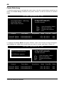
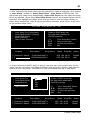
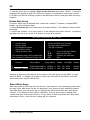
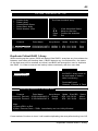
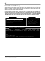
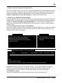
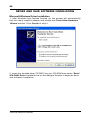
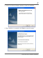
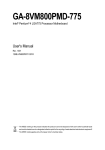
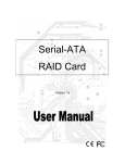
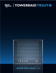
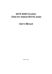
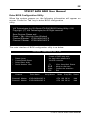
39
VT8237 SATA RAID User Manual
Enter BIOS Configuration Utility
When the system powers on, the following information will appear on
screen. Press the ‘Tab’ key to enter BIOS configuration
utility.
VIA Technologies,Inc.VIA Serial ATA RAID BIOS Setting Utility v1.00
Copyright (C) VIA Technologies,Inc.All Right reserved.
Scan Devices,Please wait . . .
Press < Tab > Key into User Window!
Channel 0 Master: IC35L040AVVA07-0
Channel 1 Master: IC35L040AVVA07-0
The main interface of BIOS configuration utility is as below:
VIA Tech. RAID BIOS Ver 1.00
8
8
8
8
8
Create Array
Delete Array
Create/Delete Spare
Select Boot Array
Serial Number View
Channel
Channel0 Master
Channel1 Master
Drive Name
Create a RAID array with
the hard disks attached to
VIA IDE controller
F1
éê
Enter
ESC
:
:
:
:
Array Name
IC35L040AVVA07-0
IC35L040AVVA07-0
View Array/disk Status
Move to next item
Confirm the selection
Exit
Mode
Size(GB)
ATA 100 38.34
ATA 100 38.34
Status
Hdd
Hdd
VT8237 SATA RAID User Manual
40
Create Disk Array
1. Use the arrow keys to navigate the main menu. Use the up and down arrow keys to
select the Create Array command and press <Enter> to call out the list of creation
steps.
VIA Tech. RAID BIOS Ver 1.00
8
8
8
8
Auto Setup For Data Security
Array Mode RAID 1 (Mirroring)
Select Disk Drives
Start Create Process
Create a RAID array with
the hard disks attached to
VIA IDE controller
F1
éê
Enter
ESC
Channel
Channel0 Master
Channel1 Master
Drive Name
Array Name
IC35L040AVVA07-0
IC35L040AVVA07-0
:
:
:
:
View Array/disk Status
Move to next item
Confirm the selection
Exit
Mode
Size(GB)
ATA 100 38.34
ATA 100 38.34
Status
Hdd
Hdd
2. Highlight the Array Mode and press <Enter>, then a list of array modes will appear.
Just highlight the target array mode that you want to create, and press <Enter> to
confirm the selection.
VIA Tech. RAID BIOS Ver 1.00
8 RAID 0 for performance
8 RAID 1 for data protection
Create a RAID array with
the hard disks attached to
VIA IDE controller
8 RAID SPAN for capacity
Channel
Channel0 Master
Channel1 Master
Drive Name
F1
éê
Enter
ESC
Array Name
IC35L040AVVA07-0
IC35L040AVVA07-0
Technical Reference Booklet
:
:
:
:
View Array/disk Status
Move to next item
Confirm the selection
Exit
Mode
Size(GB)
ATA 100 38.34
ATA 100 38.34
Status
Hdd
Hdd
41
3. After selected array mode, there are two methods to create a disk array. One method
is “Auto Setup” another is “Select Disk Drives”. Auto Setup let BIOS select the
disk drives and create array automatically. Select Disk Drives let user select the array
drives by required. When using Select Disk Drives method, the channel column will be
activated. Just highlight the target drives that you want to use and press <Enter> to
select them respectively. After all drives have been selected, press <Esc> to go back
to the creation steps menu.
VIA Tech. RAID BIOS Ver 1.00
8
8
8
8
8
Auto Setup For Performance
Array Mode RAID 0 (Striping)
Select Disk Drives
Block Size 64K
Start Create Process
Channel
[ * ]Channel0 Master
[ ]Channel1 Master
Drive Name
Create a RAID array with
the hard disks attached to
VIA IDE controller
F1
éê
Enter
ESC
:
:
:
:
View Array/disk Status
Move to next item
Confirm the selection
Exit
Array Name
Mode
IC35L040AVVA07-0
IC35L040AVVA07-0
Size(GB)
ATA 100 38.34
ATA 100 38.34
Status
Stripe0
Hdd
4. If user selected a RAID 0 array in step 2, user also can select a block size for the
array. Use the arrow key to highlight the Block Size and press <Enter>, then select a
block size from will popup. The block size can be selected from 4K to 64K Bytes.
VIA Tech. RAID BIOS Ver 1.00
8
8
8
8
8
Auto Setup For
Array Mode RAID
Select Disk Dri
Block Size 64K
Start Create Pr
Channel
[ * ]Channel0 Master
[ * ]Channel1 Master
4K
8K
16K
32K
64K
Drive Name
Create a RAID array with
the hard disks attached to
VIA IDE controller
F1
éê
Enter
ESC
Array Name
IC35L040AVVA07-0
IC35L040AVVA07-0
:
:
:
:
View Array/disk Status
Move to next item
Confirm the selection
Exit
Mode
Size(GB)
ATA 100 38.34
ATA 100 38.34
Status
Stripe0
Stripe1
Create Disk Array
42
5. Use the arrow key to highlight Start Create Process and press <Enter>. A warning
message will appear, press Y to finish the creation, or press N to cancel the creation.
6. Please note that all existing content in the hard drive will be destroyed after the array
creation.
Delete Disk Array
A specific RAID can be deleted after it has been created. To delete a created RAID,
please use the following steps:
1. Select Delete Array in the main menu and press <Enter>. The channel column will be
activated.
2. Select the member of an array that is to be deleted and press <Enter>. A warning
message will show up, press Y to delete or press N to cancel.
VIA Tech. RAID BIOS Ver 1.00
8
8
8
8
8
Create Array
Delete Array
Create/Delete Spare
Select Boot Array
Serial Number View
The selected array will be destoried
Are you sure? Conlinue? Press Y/N
Channel
Drive Name
Delete a RAID array contain
the hard disks attached to
VIA IDE controller
F1
éê
Enter
ESC
:
:
:
:
Array Name
View Array/disk Status
Move to next item
Confirm the selection
Exit
Mode
Size(GB)
[*] Channel0 Master IC35L040AVVA07-0 ARRAY 0 ATA 100 38.34
[*] Channel1 Master IC35L040AVVA07-0 ARRAY 0 ATA 100 38.34
Status
Stripe0
Stripe1
Deleting a disk array will destroy all the data on the disk array except RAID 1 arrays.
When a RAID 1 is deleted, the data on these two hard disk drives will be reserved
and become two normal disk drives.
Select Boot Array
User can select a disk array as boot device if user wants to boot operating system from
an array. Boot disk array can be not selected if user does not boot operating system
from disk array. Use the arrow key to highlight the Select Boot Disk item then press
<Enter>. The channel column will be activated. Just use arrow key to highlight the
target disk array then press <Enter>. If user select a disk array that has a boot mark
and press <Enter>, then its boot setting will be canceled.
[ * ]Channel0 Master IC35L040AVVA07-0
ATA 100 38.34
Stripe0
[ ]Channel1 Master IC35L040AVVA07-0
ATA 100 38.34
Stripe1
Technical Reference Booklet
43
VIA Tech. RAID BIOS Ver 1.00
8
8
8
8
8
Create Array
Delete Array
Create/Delete Spare
Select Boot Array
Serial Number View
Channel
Drive Name
Sct/Clear bootable array
F1
éê
Enter
ESC
:
:
:
:
Array Name
View Array/disk Status
Move to next item
Confirm the selection
Exit
Mode
Size(GB)
[*] Channel0 Master IC35L040AVVA07-0 ARRAY 0 ATA 100 38.34
[*] Channel1 Master IC35L040AVVA07-0 ARRAY 0 ATA 100 38.34
Status
Boot
Boot
Duplicate Critical RAID 1 Array
When booting up the system, BIOS will detect if the RAID 1 array has any inconsistencies
between user data and backup data. If BIOS detects any inconsistencies, the status
of the disk array will be marked as critical, and BIOS will prompt the user to duplicate
the RAID 1 in order to ensure the backup data consistency with the user data.
Critical RAID 1
Critical Status
Duplicate now
Continue to boot
the RAID 1 array needs to
be duplicated to ensure
data consistancy.
Fault Hdd Found:
Channel 1 Device 0 Fault
Remaining members of the failed array
Channel
Channel1 Device0
Channel0 Device0
Drive Name
Array Name
IC35L040AVVA07-0
Array0
IC35L040AVVA07-0
Array0
Mode Size(GB) Status
ATA 100 38.34
Mirror
ATA 100 38.34
Source
Note:
1)Press <ESC> to Exit.
2)After Execute,Press <TAB> immediately can into Utility Window!
If user selects Continue to boot, it will enable duplicating the array after booting into OS.
Duplicate Critical RAID 1 Array
44
Rebuild Broken RAID 1 Array
When booting up the system, BIOS will detect if any member disk drives of RAID has
failed or is absent. If BIOS detects any disk drive failures or missing disk drives, the
status of the array will be marked as broken.
If BIOS detects a broken RAID 1 array but there is a spare hard drive available for
rebuilding the broken array, the spare hard drive will automatically become the mirroring
drive. BIOS will show a main interface just like a duplicated RAID 1. Selecting Continue
to boot enables the user to duplicate the array after booting into operating system.
Broken RAID 1
Power off and check the failed drive
Destroy the Mirroring Relationship
Choose replacement drive and rebuild
Continue to boot
Critical Status
A disk member of a mirroring
array has failed or is not
responding.The array is
stilling functional,but fault
tolerance is disabled.
Remaining members of the failed array
Channel
Channel0 Device0
Drive Name
Array Name Mode Size(GB) Status
IC35L040AVVA07-0
Array0
ATA 100 38.34
Broken
Note:
1)Press <ESC> to Exit.
2)After Execute,Press <TAB> immediately can into Utility Window!
Technical Reference Booklet
45
1. Power off and Check the Failed Drive:
This item enables users to turn off the computer and replace the failed hard drive with a
good one. If users’ computer does not support APM, the computer would need to be
turned off manually. After the replacement, users can boot into BIOS and select 3
Choose replacement drive and rebuild to rebuild the broken array.
2. Destroy the Mirroring Relationship:
This item enables users to cancel the data mirroring relationship of the broken array. For
broken RAID 1 array, the data on the surviving disk will remain after the destroy operation.
However, Destroy the Mirroring Relationship is not recommend because the
data on the remaining disk will be lost when the hard drive is used to create another
RAID 1 array.
3. Choose Replacement Drive and Rebuild:
This item enables users to select an already-connected hard drive to rebuild the broken
array and replace the data to that particular hard drive. After choosing the item, the
channel column will be activated.
Broken RAID 1
I
Power off and check the failed drive
Destroy the Mirroring Relationship
Choose replacement drive and rebuild
Continue to boot
Critical Status
The contents on the disk
you have selected will be
deleted.
Remaining members of the failed array
Channel
Drive Name
Array Name Mode Size(GB)
( ) Channel1 Device0 IC35L040AVVA07-0
ATA 100 38.34
Status
Hdd
Note:
1)Press <ESC> to Exit.
2)After Execute,Press <TAB> immediately can into Utility Window!
Highlight the target hard drive and press <Enter>, a warning message will appear.
Press Y to use that hard drive to rebuild, or press N to cancel. Please note by
selecting option Y, all the data on the selected hard drive will be destroyed.
4. Continue to boot:
This item enables BIOS to skip the problem and continue booting into OS.
Rebuild Broken RAID 1 Array
46
DRIVER AND RAID SOFTWARE INSTALLATION
Microsoft Windows Driver Installation
1. After Windows has finished booting up, the system will automatically
find the newly installed adapter and prompt the Found New Hardware
Wizard window. Click Cancel to skip it.
2. Insert the bundled driver CD DISC into your CD-ROM drive,select “Serial
ATA RAID Driver”installation bar on the dialogue Window to begin the driver
and software installation.
Technical Reference Booklet
47
3. Confirm the follow-up dialogue windows to finish the installation.
4. When installation is completed, click Finish to restart the system.
Driver and RAID Software Installation
48
Install Operating System into SATA HDD of VT8237
Install Windows 98SE or Me
1.Make sure the HDD wanted for installing the OS is in the first hard
disk drive(C:\).
2.Install OS.
3.Install driver after OS is installed.
Install Windows NT 4.0,2000,XP
1.Insert the bundled driver CD DISC into CD-ROM(G:).Copy all files
and directories of G:\VIA chipset\SATA_Raid\DriverDisk\SATA folder to
a floppy disk.Make sure following directoties and files are copied into
floppy disk.
A:\
\Win2000
VIAsraid.inf
VIAsraid.sys
VIAsraid.cat
\Winnt40
VIAsraid.inf
VIAsraid.sys
\WinXP
VIAsraid.inf
VIAsraid.sys
VIAsraid.cat
Txtsetup.oem
VT8237
2.Install OS from CD-ROM.
3.Press “F6” when display “Press F6 if you need to install a third party
SCSI or RAID driver...”
4.Insert floppy disk.
5.Choose the OS device driver wanted for loading.
6.Install OS.
7.Install driver after OS is installed.
APPENDIX
Note to User:
1.The bundled driver CD attached an Auto-Run feature for all the drivers
that the motherboard need. Please select the drivers that you want to
install and click the button on the installation panel.
2.This motherboard support USB2.0 feature only on Windows® 2000/
XP OS.
Technical Reference Booklet
0053A8