1
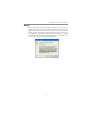
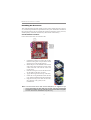
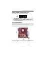
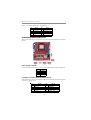
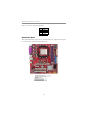
Motherboard User’s Guide This publication, including photographs, illustrations and software, is under the protection of international copyright laws, with all rights reserved. Neither this guide, nor any of the material contained herein, may be reproduced without the express written consent of the manufacturer. The information in this document is subject to change without notice. The manufacturer makes no representations or warranties with respect to the contents hereof and specifically disclaims any implied warranties of merchantability or fitness for any particular purpose. Further, the manufacturer reserves the right to revise this publication and to make changes from time to time in the content hereof without obligation of the manufacturer to notify any person of such revision or changes. Trademarks IBM, VGA, and PS/2 are registered trademarks of International Business Machines. AMD, Athlon 64 Sempron are registered trademarks of Advanced Micro Devices Inc. Microsoft, MS-DOS and Windows 2000/XP/Vista are registered trademarks of Microsoft Corporation. Award is a registered trademark of Phonex Award. Other names used in this publication may be trademarks and are acknowledged. Static Electricity Precautions 1. Don’t take this motherboard and components out of their original staticproof package until you are ready to install them. 2. While installing, please wear a grounded wrist strap if possible. If you don’t have a wrist strap, discharge static electricity by touching the bare metal of the system chassis. 3. Carefully hold this motherboard by its edges. Do not touch those components unless it is absolutely necessary. Put this motherboard on the top of static-protection package with component side facing up while installing. Pre-Installation Inspection 1. Inspect this motherboard whether there are any damages to components and connectors on the board. 2. If you suspect this motherboard has been damaged, do not connect power to the system. Contact your motherboard vendor about those damages. Copyright © 2007 All Rights Reserved A15G Series, V1.0 November 2007 i Motherboard User’s Guide Table of Contents Trademark ............................................................................................................ i Chapter 1: Introduction ..................................................................................... 1 Key Features .................................................................................................................... 1 Package Contents ........................................................................................................... 4 Chapter 2: Motherboard Installation .............................................................. 5 Motherboard Components ............................................................................................ 6 I/O Ports .......................................................................................................................... 7 Installing the Processor ................................................................................................. 7 Installing Memory Modules .......................................................................................... 8 Jumper Settings ............................................................................................................ 1 0 Install the Motherboard ............................................................................................... 11 Connecting Optional Devices ..................................................................................... 1 2 Install Other Devices .................................................................................................... 1 4 Expansion Slots ............................................................................................................ 1 6 Chapter 3: BIOS Setup Utility ....................................................................... 18 Introduction .................................................................................................................. 1 8 Running the Setup Utility ......................................................................................... ..18 Standard CMOS Setup Page ....................................................................................... 1 9 Advanced BIOS Features Page .................................................................................. 2 1 Advanced Chipset Features Page ............................................................................... 2 5 Integrated Peripherals Page..............................................................................28 Power Management Setup Page ................................................................................. 3 2 PnP/PCI Configurations Page .................................................................................... 3 4 PC Health Status Page ................................................................................................ 3 4 Load Fail-Safe Defaults .............................................................................................. 3 6 Load Optimized Defaults ............................................................................................. 3 6 Set Supervisor/User Password ..................................................................................... 3 6 Save & Exit setup ......................................................................................................... 3 7 Exit without saving ....................................................................................................... 3 7 Chapter 4: Software & Applications .............................................................. 38 Introduction .................................................................................................................. 3 8 Installing Support Software ........................................................................................ 3 8 Bundled Software Installation .................................................................................... 4 2 Chapter 5: Setting Up NVIDIA RAID Configuration ................................... 43 Setting Up a Non-Bootable RAID Array ................................................................... 4 3 Setting Up a Bootable RAID Array .................................................................. 46 ii Motherboard User’s Guide Notice: 1. Owing to Microsoft’s certifying schedule is various to every supplier, we might have some drivers not certified yet by Microsoft. Therefore, it might happen under Windows XP that a dialogue box (shown as below) pops out warning you this software has not passed Windows Logo testing to verify its compatibility with Windows XP. Please rest assured that our RD department has already tested and verified these drivers. Just click the “Continue Anyway” button and go ahead the installation. iii Motherboard User’s Guide Chapter 1 Introduction This motherboard has a socket AM2+/AM2 supporting the newest and advanced TM TM TM TM AMD Phenom /Athlon 64 X2 Dual-Core/Athlon 64/Sempron CPUs TM with 2000 MT/s HyperTransport (HT) interface Speeds. This motherboard is based on NVIDIA® MCP61P/MCP61S that supports the Serial ATA interface for high-performance and mainstream desktop PCs, and the built-in USB 2.0 providing higher bandwidth, implementing USB 2.0 EHCI and USB 1.1 OHCI. It supports High Definition Audio Codec and provides one IDE Ultra DMA 133/100/66/33 channel. It has one PCI Express x16 slot (MCP61S only supports PCI Express x8), one PCI Express x1 slot and two 32-bit PCI slots. There is a full set of I/O ports including two PS/2 ports for mouse and keyboard, one parallel port, one serial port, VGA1, one LAN port, four back-panel USB2.0 ports, and audio jacks for microphone, line-in and 6/8-channel (optional) line-out. Onboard USB header(s) can provide extra ports by connecting the Extended USB Module to the motherboard. This motherboard is a Micro ATX size motherboard and has power connectors for an ATX power supply. Key Features The key features of this motherboard include: Socket-AM2+/AM2 Processor Support TM TM • Supports socket AM2+/AM2 for AMD Phenom /Athlon 64 X2 DualTM TM Core/Athlon 64/Sempron processors • Supports up to 2000 MT/s HyperTransportTM interface Speeds Note: HyperTransport Technology is a point-to-point link between two devices, it enables integrated circuits to exchange information at much higher speeds than currently available interconnect technologies. Chipset The NVIDIA® MCP61P/MCP61S is a single-chip with proven reliability and performance. • 1 GHz HyperTransport x16 up and down links to the AM2+/AM2 CPUs • PCI Express 16 lane link interface for external graphics processors (MCP61S only supports PCI Express 8 lane link interface for other peripherals) • PCI 2.3 interface at 33 MHz • Integrated SATA 3.0 Gb/s Host Controller • USB 2.0 ports supported • Fast ATA-133 IDE controller 1 Motherboard User’s Guide Memory Support • Two 240-pin DIMM slots for DDR2 SDRAM memory modules • Supports Dual Channel DDR2 800/667/533/400 memory bus • Maximum installed memory is 16* GB (* Duo to the DRAM maximum size is 2 GB at present, the memory maximum size we have tested is 4 GB.) Expansion Slots • One PCI Express x16 slot (MCP61S only supports PCI Express x8) • One PCI Express x1 slot • Two 32-bit PCI slots Onboard IDE channels • One IDE Connector • Supports PIO (Programmable Input/Output) and DMA (Direct Memory Access) modes • Supports IDE Ultra DMA bus mastering with transfer rates of 133/100/66/ 33 MB/sec Serial ATA • Four Serial ATA Connectors • Compliant with the SATA2 with 3.0 Gb/s per direction per channel Audio Codec (optional) • • • • • • • • • • • • • • • • • • • 7.1+2 Channel High Definition Audio Codec All DACs support 192K/96K/48K/44.1KHz DAC sample rate Software selectable 2.5V/3.75V VREPOUT Meets Microsoft WHQL/WLP 2.x audio requirements TM Direct Sound 3D compatible 7.1 Channel High Definition Audio Codec ADC support 148K/96K sample rate High quality differential CD input Power Support: Digital: 3.3V; Analog: 5.0V Meets Microsoft WHQL/WLP 2.0 audio requirements TM Direct Sound 3D compatible 5.1 Channel Hifh Definition Audio Codec ADCs support 44.1/48k/96k sample rate Meets Microsoft WHQL/WLP 3.0x audio requirements TM Direct Sound 3D compatible 5.1 Channel Hifh Definition Audio Codec ADCs support 44.1/48k/96k sample rate Meets Microsoft WLP 3.08 Vista premium and mobile PCs audio requirements TM Direct Sound 3D compatible 2 Chapter 1: Introduction Onboard I/O Ports • Two PS/2 ports for mouse and keyboard • One parallel port • One serial port • One VGA port • Four back-panel USB2.0 ports • One LAN port • Audio jacks for microphone, line-in and 6/8-channel (optional) line-out Fast Ethernet LAN • 10Base-T/100BASE-TX IEEE 802.3u fast Ethernet transceiver • Low-power mode • MII and 7-wire serial interface USB 2.0 • Compliant with Universal Serial Bus Specification Revision 2.0 • Compliant with Open Host Controller Interface Specification Revision 1.1 BIOS Firmware This motherboard uses Award BIOS that enables users to configure many system features including the following: • Power management • Wake-up alarms • CPU parameters and memory timing • CPU and memory timing The firmware can also be used to set parameters for different processor clock speeds. Dimensions • Micro-ATX form factor of 244 x 214 mm Note: Hardware specifications and software items are subject to change without notification. 3 Motherboard User’s Guide Package Contents Your motherboard package ships with the following items: The motherboard The User’s Guide One diskette drive ribbon cable (optional) One IDE drive ribbon cable The Software support CD Optional Accessories You can purchase the following optional accessories for this motherboard. The Extended USB module The Serial ATA cable The Serial ATA power cable Note: You can purchase your own optional accessories from the third party, but please contact your local vendor on any issues of the specification and compatibility. 4 Chapter 2: Motherboard Installation Chapter 2 Motherboard Installation To install this motherboard in a system, please follow these instructions in this chapter: Identify the motherboard components Install a CPU Install one or more system memory modules Make sure all jumpers and switches are set correctly Install this motherboard in a system chassis (case) Connect any extension brackets or cables to headers/connectors on the motherboard Install peripheral devices and make the appropriate connections to headers/ connectors on the motherboard Note: 1 2 Before installing this motherboard, make sure jumper CLR_CMOS is under Normal setting. See this chapter for information about locating CLR_CMOS and the setting options. Never connect power to the system during installation; otherwise, it may damage the motherboard. 5 Motherboard User’s Guide Motherboard Components ITEM LABEL COMPONENTS Socket AM 2+/AM 2 for AM D PhenomTM/AthlonTM 64 1 CPU Socket 2 3 4 5 6 7 8 9 DIM M 1~2 FDD PWR1 IDE1 SPK1 SATA1~4 CLR_CM OS PANEL1 X2 Dual-Core/AthlonTM 64/SempronTM processors 240-pin DDR2 SDRAM slots Floppy disk drive connector Standard 24-pin ATX power connector Primary IDE connector Speaker header Serial ATA connectors Clear CM OS jumper Front panel switch/LED header 10 11 12 13 14 15 16 17 18 19 20 21 USBPWR_F F_USB1~3 SYS_FAN SPDIFO1 CD_IN F_AUDIO PCI1~2 PCIEX1 PCIEX16 USBPWR_R PWR2 CPU_FAN Front Panel USB Power Select Jumper Front Panel USB headers System cooling fan connector SPDIF out header Analog audio input header Front panel audio header 32-bit add-on card slots PCI Express x1 slot PCI Express x16 slot for graphics interface Rear Panel USB PS/2 Power Select Jumper 4-pin +12V power connector CPU cooling fan connector 6 Chapter 2: Motherboard Installation I/O Ports (optional) The illustration below shows a side view of the built-in I/O ports on the motherboard. PS/2 Mouse Use the upper PS/2 port to connect a PS/2 pointing device. PS/2 Keyboard Use the low er PS/2 port to connect a PS/2 keyboard. Parallel Port (LPT) Use the Parallel port to connect printers or other parallel communications devices. Serial Port (COM1) Use the COM port to connect serial devices such as mice or fax/modems. VGA1 Port Use the VGA1 port to connect the VGA devices. LAN Port Connect an RJ-45 jack to the LAN port to connect your computer to the Netw ork. USB Ports Use the USB ports to connect USB devices. Audio Ports (optional) Use these three audio jacks to connect audio devices. The first jack is for stereo Line-In signal, the second jack for stereo Line-Out signal, and the third jack for Microphone. Use these audio jacks to connect audio devices. The Aport is for stereo Line-In signal, w hlie the C port is for microphone in signal. The motherboard supports 8-channel audio devices that correspond to A, B, D and E port respectively. In addition, all of the three ports, A, B and D provide users w ith both right & left channels individually. 7 Motherboard User’s Guide Installing the Processor This motherboard has an AM2+/AM2 processor socket. When choosing a processor, consider the performance requirements of the system. Performance is based on the processor design, the clock speed and system bus frequency of the processor, and the quantity of internal cache memory and external cache memory. CPU Installation Procedure Follow these instructions to install the CPU: 1 2 3 4 5 6 Unhook the locking lever of the CPU socket. Pull the locking lever away from the socket and raising it to the upright position. Match the pin1 corner marked as the beveled edge on the CPU with the pin1 corner on the socket. Insert the CPU into the socket. Do not use force. Push the locking lever down and hook it under the latch on the edge of socket. Apply thermal grease to the top of the CPU. Install the cooling fan/heatsink unit onto the CPU, and secure them all onto the socket base. Plug the CPU fan power cable into the CPU fan connector (CPU_FAN) on the motherboard. Note: To achieve better airflow rates and heat dissipation, we suggest that you use a high quality fan with 4800 rpm at least. CPU fan and heatsink installation procedures may vary with the type of CPU fan/heatsink supplied. The form and size of fan/heatsink may also vary. 8 Chapter 2: Motherboard Installation Installing Memory Modules This motherboard accommodates two 240-pin DIMM sockets (Dual Channel Memory Module) for unbuffered DDR2 800/667/533/400 memory modules (Double Data Rate SDRAM), and maximum 16* GB installed memory. Over its predecessor, DDR2-SDRAM offers greater bandwidth and density in a smaller package along with a reduction in power consumption. In addition, DDR2SDRAM offers new features and functions that enable a higher clock rate and data rate operations of 800/667/533/400 MHz. DDR2 transfers 64 bits of data twice every clock cycle. Memory Module Installation Procedure These modules can be installed with up to 16* GB system memory. Refer to the following to install the memory module. 1. Push down the latches on both sides of the DIMM socket. 2. Align the memory module with the socket. There is a notch on the DIMM socket that you can install the DIMM module in the correct direction. Match the cutout on the DIMM module with the notch on the DIMM socket. 3. Install the DIMM module into the socket and press it firmly down until it is seated correctly. The socket latches are levered upwards and latch on to the edges of the DIMM. 4. Install any remaining DIMM modules. 9 Motherboard User’s Guide Note for dual-channel DDR2: 1. You CAN NOT use only one DIMM2 for it might cause the system shutdown. 2. You need to use DIMM1 and DIMM2 with the same size of memory modules. Jumper Settings Connecting two pins with a jumper cap is SHORT; removing a jumper cap from these pins, OPEN. CLR_CMOS: Clear CMOS Jumper Use this jumper to clear the contents of the CMOS memory. You may need to clear the CMOS memory if the settings in the Setup Utility are incorrect and prevent your motherboard from operating. To clear the CMOS memory, disconnect all the power cables from the motherboard and then move the jumper cap into the CLEAR setting for a few seconds. 1 CLR_CMOS Function Jum per NORMAL Short Pins 1-2 CLEAR CMOS Short Pins 2-3 Note: To avoid the system unstability after clearing CMOS, we recommend users to enter the main BIOS setting page to “Load Optimal De-faults” and then “Save Changes and Exit”. USBPWR_F: FRONT PANEL USB POWER SELECT Jumper Use this jumper to set the Front Panel USB Power function. 1 USBPWR_F Function VCC5 VCC5_DUAL Jum per Setting Short Pins 1-2 Short Pins 2-3 10 Chapter 2: Motherboard Installation USBPWR_R: REAR USB PS/2 POWER SELECT Jumper Use this jumper to set the Rear USB PS/2 Power function. 1 USBPWR_R Function VCC5 VCC5_DUAL Jum per Setting Short Pins 1-2 Short Pins 2-3 Note:1. Make sure the power supply provides enough VCC5_DUAL voltage before selecting the VCC5_DUAL function. 2. It is required that users place the USBPWR_F & USBPWR_R cap onto 2-3 pin rather than 1-2 pin as default if you want to wake up the computer by USB/PS2 KB/Mouse. Install The Motherboard Install the motherboard in a system chassis (case). The board is an micro-ATX size motherboard. You can install this motherboard in an ATX case. Make sure your case has an I/O cover plate matching the ports on this motherboard. Install the motherboard in a case. Follow the case manufacturer’s instructions to use the hardware and internal mounting points on the chassis. Connect the power connector from the power supply to the PWR1 connector on the motherboard. PWR2 is a +12V connecotr for CPU Vcore power. If there is a cooling fan installed in the system chassis, connect the system cooling fan cable to the SYS_FAN fan power connector on the motherboard. Connect the case switches and indicator LEDs to the PANEL1 header. 11 Motherboard User’s Guide Here is a list of the PANEL1 pin assignments. Pin 1 3 5 7 9 Signal HD_LED_P(+) HD_LED_N(-) RESET_SW_N(-) RESET_SW_P(+) RSVD Pin 2 4 6 8 10 Signal FP PWR/SLP(+) FP PWR/SLP(-) POWER_SW_P(+) POWER_SW_N(-) KEY Connecting Optional Devices Refer to the following for information on connecting the motherboard’s optional devices: SPK1: Speaker Header Connect the cable from the PC speaker to the SPK1 header on the motherboard. Pin 1 2 3 4 Sig n al V CC Key GND Signal F_AUDIO: Front Panel Audio Header (optional) This header allows the user to install auxiliary front-oriented microphone and lineout ports for easier access. Pin 1 3 5 7 9 Signal PORT 1L PORT 1R PORT 2R SENCE_SEND PORT 2L Pin 2 4 6 8 10 12 Signal GND PRESENCE# Sense1_return KEY Sense2_return Chapter 2: Motherboard Installation F_USB1~3: Front Panel USB Headers The motherboard has USB ports installed on the rear edge I/O port array. Additionally, some computer cases have USB ports at the front of the case. If you have this kind of case, use auxiliary USB headers F_USB1~3 to connect the front-mounted ports to the motherboard. Here is a list of USB pin assignments. Pin 1 3 5 7 9 Signal USBPWR0 USB_FP_P0(-) USB_FP_P0(+) GND KEY Pin 2 4 6 8 10 Signal USBPWR0 USB_FP_P1(-) USB_FP_P1(+) GND USB_FP_OC0 1. Locate the F_USB1~3 header on the motherboard. 2. Plug the bracket cable onto the F_USB1~3 header. 3. Remove a slot cover from one of the expansion slots on the system chassis. Install an extension bracket in the opening. Secure the extension bracket to the chassis with a screw. SPDIFO1: S/PIF Out Header S/PDIF (Sony/Plilips Digital Interface) is a standard audio transfer file format and allows the transfer of digatal audio signals from one device to another without having to be converted first to an analog format. Via a specific audio cable, you can connect the SPDIFO1 header (S/PDIF output) on the motherboard to the S/PDIF digital input on the external speakers or AC Decode devices. Pin 1 2 3 4 Signal SPDIFOUT 5VA Key GND 13 Motherboard User’s Guide Install Other Devices Install and connect any other devices in the system following the steps below. Floppy Disk Drive The motherboard ships with a floppy disk drive cable that can support one or two drives. Drives can be 3.5" or 5.25" wide, with capacities of 360K, 720K, 1.2MB, 1.44MB, or 2.88MB. Install your drives and connect power from the system power supply. Use the cable provided to connect the drives to the floppy disk drive connector FDD. IDE Devices IDE devices include hard disk drives, high-density diskette drives, and CD-ROM or DVD-ROM drives, among others. The mainboard ships with an IDE cable that can support one or two IDE devices. If you connect two devices to a single cable, you must configure one of the drives as Master and one of the drives as Slave. The documentation of the IDE device will tell you how to configure the device as a Master or Slave device. The Master device connects to the end of the cable. Install the device(s) and connect power from the system power supply. Use the cable provided to connect the device(s) to the Primary IDE channel connector IDE1 on the motherboard. 14 Chapter 2: Motherboard Installation Serial ATA Devices The Serial ATA (Advanced Technology Attachment) is the standard interface for the IDE hard drives, which is designed to overcome the design limitations while enabling the storage interface to scale with the growing media rate demands of PC platforms. It provides you a faster transfer rate of 3.0 Gb/s. If you have installed a Serial ATA hard drive, you can connect the Serial ATA cables to the Serial ATA hard drive or the connector on the motherboard. On the motherboard, locate the Serial ATA connectors SATA1-4, which support new Serial ATA devices for the highest data transfer rates, simpler disk drive cabling and easier PC assembly. It eliminates limitations of the current Parallel ATA interface, but maintains register compatibility and software compatibility with Parallel ATA. Analog Audio Input Header If you have installed a CD-ROM drive or DVD-ROM drive, you can connect the drive audio cable to the onboard sound system. When you first start up your system, the BIOS should automatically detect your CD-ROM/DVD drive. If it doesn’t, enter the Setup Utility and configure the CDROM/DVD drive that you have installed. On the motherboard, locate the 4-pin header CD_IN. 15 Motherboard User’s Guide Here is a list of CD_IN pin assignments. Pin 1 2 3 Signal CD_L GND GND 4 CD_R Expansion Slots This motherboard has one PCI Ex16 slot (MCP61S only supports PCI Express x8), one PCI Ex1 slot and two 32-bit PCI slots. 16 Chapter 2: Motherboard Installation Follow the steps below to install an PCI Express x16/PCI Express x1/PCI expansion card. 1. Locate the PCI Express x16, PCI Express x1 and PCI slots on the mainboard. 2. Remove the blanking plate of the slot from the system chassis. 3. Install the edge connector of the expansion card into the slot. Ensure the edge connector is correctly seated in the slot. 4. Secure the metal bracket of the card to the system chassis with a screw. PCI Express x16 slot The one PCI Express x16 slot is fully compliant to the PCI Express Base Specification revision 1.1 as well. PCI Express x1 Slot The one PCI Express x1 slot is fully compliant to the PCI Express Base Specification revision 1.1 as well. PCI Slots You can install the 32-bit PCI interface expansion cards in the slots. 17 Motherboard User’s Guide Chapter 3 BIOS Setup Utility Introduction The BIOS Setup Utility records settings and information of your computer, such as date and time, the type of hardware installed, and various configuration settings. Your computer applies the information to initialize all the components when booting up and basic functions of coordination between system components. If the Setup Utility configuration is incorrect, it may cause the system to malfunction. It can even stop your computer booting properly. If it happens, you can use the clear CMOS jumper to clear the CMOS memory which has stored the configuration information; or you can hold down the Page Up key while rebooting your computer. Holding down the Page Up key also clears the setup information. You can run the setup utility and manually change the configuration. You might need to do this to configure some hardware installed in or connected to the motherboard, such as the CPU, system memory, disk drives, etc. Running the Setup Utility Every time you start your computer, a message appears on the screen before the operating system loading that prompts you to “Hit <DEL> if you want to run SETUP”. Whenever you see this message, press the Delete key, and the Main menu page of the Setup Utility appears on your monitor. Phonex-AwardBIOS CMOS Setup Utility Standard CMOS Features Advanced BIOS Features Advanced Chipset Features Integrated Peripherals Power Management Setup PnP/PCI Configurations PC Health Status Load Fail-Safe Defaults Load Optimized Defaults Set Supervisor Password Set User Password Save & Exit Setup Exit without Saving : Select Item Esc: Quit F10: Save & Exit Setup Time, Date, Hard Disk Type... You can use cursor arrow keys to highlight anyone of options on the main menu page. Press Enter to select the highlighted option. Press the Escape key to leave the setup utility. Press +/-/ to modify the selected field’s values. 18 Chapter 3: BIOS Setup Utility Some options on the main menu page lead to tables of items with installed values that you can use cursor arrow keys to highlight one item, and press PgUp and PgDn keys to cycle through alternative values of that item. The other options on the main menu page lead to dialog boxes requiring your answer OK or Cancel by selecting the [OK] or [Cancel] key. If you have already changed the setup utility, press F10 to save those changes and exit the utility. Press F1 to display a screen describing all key functions. Press F9 to install the setup utility with a set of default values. Standard CMOS Features Page This page displays a table of items defining basic information about your system. Phonex-AwardBIOS CMOS Setup Utility Standard CMOS Features Date (mm:dd:yy) Time (hh:mm:ss) f f f f IDE IDE IDE IDE Channel Channel Channel Channel 0 0 2 3 Master Slave Master Master Mon, Jan. 8 2007 9 : 14 : 38 [None] [None] [None] [None] Item Help Menu Level f Change the day, month, year and century Drive A [1.44M, 3.5 in.] Video Halt On Setting [EGA/VGA] [All, But Keyboard] Base Memory Extended memory Total Memory 640K 1047552K 1048576K : Move Enter: Select +/-/: Value F10: Save Esc: Exit F1: General Help F5: Previous Values F6: Fial-Safe Defaults F7: Optimized Defaults Date & Time These items set up system date and time. 19 Motherboard User’s Guide f IDE Devices Your computer has one IDE channel which can be installed with one or two devices (Master and Slave). Use these items to configure each device on the IDE channel. Phonex-AwardBIOS CMOS Setup Utility IDE Channel 0 Master IDE HDD Auto-Detection [Press Enter] IDE Channel 0 Master Access Mode [Auto] [Auto] Capacity 80 GB Cylinder Head Precomp Landing Zone Sector 38309 16 0 38308 255 Item Help Menu Level ff To auto-detect the HDD’s size, head... on this channel : Move Enter: Select +/-/: Value F10: Save Esc: Exit F1: General Help F5: Previous Values F6: Fial-Safe Defaults F7: Optimized Defaults IDE HDD Auto-Detection Press <Enter> while this item is highlighted to prompt the Setup Utility to automatically detect and configure an IDE device on the IDE channel. Note: If you are setting up a new hard disk drive that supports LBA mode, more than one line will appear in the parameter box. Choose the line that lists LBA for an LBA drive. IDE Channel 0/2/3 Master & IDE Channel 0 Slave Leave this item at Auto to enable the system to automatically detect and configure IDE devices on the channel. If it fails to find a device, change the value to Manual and then manually configure the drive by entering the characteristics of the drive in the items described below. Note: Before attempting to configure a hard disk drive, ensure that you have the configuration information supplied by the manufacturer of your hard drive. Incorrect settings can result in your system not recognizing the installed hard disk. Access Mode (Auto) This item defines ways that can be used to access IDE hard disks such as LBA (Large Block Addressing). Leave this value at Auto and the system will automatically decide the fastest way to access the hard disk drive. Press <Esc> to return to the Standard CMOS Features page. 20 Chapter 3: BIOS Setup Utility Drive A This item define the characteristics of any diskette drive attached to the system. You can connect one or two diskette drives. Video This item defines the video mode of the system. The motherboard has a built-in VGA graphics system; you must leave this item at the default value. Halt On This item defines the operation of the system POST (Power On Self Test) routine. You can use this item to select which types of errors in the POST are sufficient to halt the system. Base Memory, Extended Memory, and Total Memory These items are automatically detected by the system at start up time. These are display-only fields. You cannot make changes to these fields. Press <Esc> to return to the main menu setting page. Advanced BIOS Features Page This page sets up more advanced information about your system. Handle this page with caution. Any changes can affect the operation of your computer. [Press Enter] [Press Enter] [Press Enter] [Press Enter] [Enabled] [Enabled] [Enabled] [Removable] [Hard Disk] [CDROM] [Enabled] [Disabled] [On] [Fast] [Disabled] 6 250 [Setup] [Enabled] Item Help Menu Level f 123 123 123 123 123 f f CPU Feature f Removable Device Priority f Hard Disk Boot Priority f Network Boot Priority CPU Internal Cache External Cache Quick Power On Self Test First Boot Device Second Boot Device Third Boot Device Boot Other Device Boot Up Floppy Seek Boot Up NumLock Status Gate A20 Option Typematic Rate Setting X Typematic Rate (Chars/Sec) X Typematic Delay (Msec) Security Option APIC Mode f Phonex-AwardBIOS CMOS Setup Utility Advanced BIOS Features : Move Enter: Select +/-/: Value F10: Save Esc: Exit F1: General Help F5: Previous Values F6: Fial-Safe Defaults F7: Optimized Defaults 21 Motherboard User’s Guide f CPU Feature (Press Enter) Scroll to this item and press <Enter> to view the following screen: Phonex-AwardBIOS CMOS Setup Utility CPU Feature Virtulization AMD K8 Cool&Quit control Item Help [Enabled] [Auto] Menu Level ff : Move Enter: Select +/-/: Value F10: Save Esc: Exit F1: General Help F5: Previous Values F6: Fial-Safe Defaults F7: Optimized Defaults Virtualization Hardware Virtualization Technology enables processor feature for running multiple simultaneous Virtual Machines allowing specialized software applications to run in full isolation of each other. AMD K8 Cool & Quiet Control This item helps the system to lower the frequency when CPU idles. When the frequency decreases, the temperature will drop automatically as well. Press <Esc> to return to Advanced BIOS Features page. f Removable Device Priority (Press Enter) Scroll to this item and press <Enter> to view the following screen: Phonex-AwardBIOS CMOS Setup Utility Removable Device Priority Item Help 1. Floppy Disks Menu Level ff Use < m > or < n > to select a device, then press <+> to move it up, or <-> to move it down the list. Press < ESC > to exit this menu. : Move Enter: Select +/-/: Value F10: Save Esc: Exit F1: General Help F5: Previous Values F6: Fial-Safe Defaults F7: Optimized Defaults Press <Esc> to return to Advanced BIOS Features page. 22 Chapter 3: BIOS Setup Utility f Hard Disk Boot Priority (Press Enter) Scroll to this item and press <Enter> to view the following screen: Phonex-AwardBIOS CMOS Setup Utility Hard Disk Boot Priority Item Help 1. Ch2 M : WDCWD1600JS-22MHB0 2. Bootable Add-in Cards Menu Level ff Use < m > or < n > to select a device, then press <+> to move it up, or <-> to move it down the list. Press < ESC > to exit this menu. : Move Enter: Select +/-/: Value F10: Save Esc: Exit F1: General Help F5: Previous Values F6: Fial-Safe Defaults F7: Optimized Defaults Press <Esc> to return to Advanced BIOS Features page. f CD-ROM Boot Priority (Press Enter) Scroll to this item and press <Enter> to view the following screen: Phonex-AwardBIOS CMOS Setup Utility Network Boot Priority Item Help 1. Network 0: NVIDIA Boot Agent 227.0524 Menu Level ff Use < m > or < n > to select a device, then press <+> to move it up, or <-> to move it down the list. Press < ESC > to exit this menu. : Move Enter: Select +/-/: Value F10: Save Esc: Exit F1: General Help F5: Previous Values F6: Fial-Safe Defaults F7: Optimized Defaults Press <Esc> to return to Advanced BIOS Features page. CPU Internal Cache All processors that can be installed in this motherboard use internal level 1 (L1) cache memory to improve performance. Leave this item at the default value for better performance. External Cache Most processors that can be installed in this system use external level 2 (L2) cache memory to improve performance. Leave this item at the default value for better performance. 23 Motherboard User’s Guide Quick Power On Self Test Enable this item to shorten the power on testing (POST) and have your system start up faster. You might like to enable this item after you are confident that your system hardware is operating smoothly. First/Second/Third Boot Device Use these three items to select the priority and order of the devices that your system searches for an operating system at start-up time. Boot Other Device When enabled, the system searches all other possible locations for an operating system if it fails to find one in the devices specified under the First, Second, and Third boot devices. Boot Up Floppy Seek If this item is enabled, it checks the size of the floppy disk drives at start-up time. You don’t need to enable this item unless you have a legacy diskette drive with Boot Up NumLock Status This item defines if the keyboard Num Lock key is active when your system is started. Gate A20 Option This item defines how the sytem handles legacy software that was written for an earlier generation of processors. Leave this item at the default value. Typematic Rate Setting If this item is enabled, you can use the following two items to set the typematic rate and the typematic delay settings for your keyboard. • • Typematic Rate (Chars/Sec): Use this item to define how many characters per second are generated by a held-down key. Typematic Delay (Msec): Use this item to define how many milliseconds must elapse before a held-down key begins generating repeat characters. Security Option If you have installed password protection, this item defines if the password is required at system start up, or if it is only required when a user tries to enter the Setup Utility. APIC Mode This item allows you to enable or disable the APIC (Advanced Programmable Interrupt Controller) mode. APIC provides symmetric multi-processing (SMP) for systems, allowing support for up to 60 processors. MPS Version Control For OS This item displays MPS version control for OS. 24 Chapter 3: BIOS Setup Utility Small Logo (EPA) Show Enables or disables the display of the EPA logo during boot. Summary Screen Show Enables or disables the display of the summary screen during boot. ATA 66/100 IDE Cable Msg. This item enables or disables the display of the ATA 66/100 Cable MSG. Press <Esc> to return to the main menu setting page. Advanced Chipset Features Page These items define critical timing parameters of the motherboard. You should leave the items on this page at their default values unless you are very familiar with the technical specifications of your system hardware. If you change the values incorrectly, you may introduce fatal errors or recurring instability into your system. Phonex-AwardBIOS CMOS Setup Utility Advanced Chipset Features Frame Buffer Size GPU Bank Flip PMU CPU Frequency K8<->NB HT Speed K8<->NB HT Width f DRAM Configuration PCIE Spread Spectrum SATA Spread Spectrum HT Spread Spectrum PCIE Clock SSE/SSE2 Instructions System BIOS Cacheable [Auto] [Disabled] [Disabled] [200.0] [Auto] [Auto] [Press Enter] [Disabled] [Disabled] [Disabled] [100Mhz] [Enabled] [Disabled] Item Help Menu Level f : Move Enter: Select +/-/: Value F10: Save Esc: Exit F1: General Help F5: Previous Values F6: Fial-Safe Defaults F7: Optimized Defaults Frame Buffer Size This item enables users to specify the Onboard VGA share memory size. GPU Bank Flip This item enables or disables GPU Bank flip. PMU This item enables or disables ACPI power management unit function. K8 <-> NB HT Speed This item enables users to set the speed of HyperTransport between the CPU and Northbridge. K8 <-> NB HT Width This item enables users to set the HyperTransport width between CPU and the Northbridge . 25 Motherboard User’s Guide f DRAM Configuration (Press Enter) Scroll to this item and press <Enter> to view the following screen: Phonex-AwardBIOS CMOS Setup Utility DRAM Configuration Timing Mode X Memory Clock value or Limit DDR2 400 DQS Training Control DCTs Mode CKE base power down mode CKE based powerdown Memclock tri-stating Auto Optimaze Bottom IO X Bootom of [31:24] IO space E0 Bottom of URAM [31:24] [FC] Item Help [Auto] [Skip DQS] [Ganged] [Disabled] [Per Channel] [Disabled] [Enabled] Menu Level ff Auto, no user limit MaxMemClk, limit by Memory Clock value : Move Enter: Select +/-/: Value F10: Save Esc: Exit F1: General Help F5: Previous Values F6: Fial-Safe Defaults F7: Optimized Defaults Timing Mode This item allows you to set up the DRAM timing nanually or automatically. • Memory Clock value or Limi (DDR2 400) When DDR2 Timing Setting by is set to Manual, use this item to set the DRAM frequency. DQS Training Control DQS training is used to place the DQS strobe in the center of the data eye. DCTs Mode This item is used to select the mode of Dram ConTrollers. CKE base power down mode When in power down mode, if all pages of the DRAMs associated with a CKE pin are closed, then these parts are placed in power down mode. Only pre-charge power down mode is supported, not active power down mode. CKE based powerdown The DRAM channel is placed in power down when all chip selects associated with the channel are idle. Memclock tri-stating This item enables or disables memclock tri-stating function. Auto Optimize Bottom IO This item is used to set the Auto Optimized Bottom IO. • Bottom of [31:24] IO space (E0) This item is used to select the memory that will be remapped higher than 00E0. 26 Chapter 3: BIOS Setup Utility Bottom of UMA DRAM [31:24] (FC) This item is used to set the bottom of UMA DRAM [31:24]. We strongly recommend that you leave this item at its default setting. Press <Esc> to return to Advanced Chipset Features page. PCIE Spread Spectrum This item, when enabled, can significantly reduce the EMI (Electromagnetic Interference) generated by the PCIE. SATA Spread Spectrum This item, when enabled, can significantly reduce the EMI (Electromagnetic Interference) generated by the SATA. HT Spread Spectrum This item, when enabled, can significantly reduce the EMI (Electromagnetic Interference) generated by the HT. PCIE Clock This item is used to set the frequency of PCIE clock. SSE/SSE2 Instructions This item enables or disables SSE/SSE2 instructions. System BIOS Cacheable This item enables users to enable or disable the system BIOS cache. Press <Esc> to return to the main menu setting page. 27 Motherboard User’s Guide Integrated Peripherals Page These options display items that define the operation of peripheral components on the system’s input/output ports. Phonex-AwardBIOS CMOS Setup Utility Integrated Peripherals f f f f IDE Function Setup RAID Config Onboard Device Setup Super IO Device [Press [Press [Press [Press Enter] Enter] Enter] Enter] Item Help Menu Level f : Move Enter: Select +/-/: Value F10: Save Esc: Exit F1: General Help F5: Previous Values F6: Fial-Safe Defaults F7: Optimized Defaults X IDE Function Setup (Press Enter) Scroll to this item and press <Enter> to view the following screen: Phonex-AwardBIOS CMOS Setup Utility IDE Function Setup OnChip IDE Channel 0 Primary Master PIO Primary Slave PIO Primary Maste UDMA Primary Slave UDMA Secondary Master UDMA Secondary Slave UDMA IDE DMA transfer access Serial-ATA Controller IDE Prefetch Mode IDE HDD Block Mode [Enabled] [Auto] [Auto] [Auto] [Auto] [Auto] [Auto] [Enabled] [Enabled] [Enabled] [Enabled] Item Help Menu Level ff : Move Enter: Select +/-/: Value F10: Save Esc: Exit F1: General Help F5: Previous Values F6: Fial-Safe Defaults F7: Optimized Defaults On-Chip IDE Channel 0 Use these items to enable or disable the PCI IDE channels that are integrated on the motherboard. Primary Master/Slave PIO Each IDE channel supports a master device and a slave device. These four items let you assign the kind of PIO (Programmed Input/Output) was used by the IDE devices. Choose Auto to let the system auto detect which PIO mode is best, or select a PIO mode from 0-4. 28 Chapter 3: BIOS Setup Utility Primary/Secondary Master/Slave UDMA Each IDE channel supports a master device and a slave device. This motherboard supports UltraDMA technology, which provides faster access to IDE devices. If you install a device that supports UltraDMA, change the appropriate item on this list to Auto. You may have to install the UltraDMA driver supplied with this motherboard in order to use an UltraDMA device. IDE DMA transfer access This item allows you to enable the transfer access of the IDE DMA then burst onto the PCI bus and nonburstable transactions do not. Serial-ATA Controller This item allows you to enable or disable the onboard SATA controller. IDE Prefetch Mode The onboard IDE drive interface supports IDE prefetching, for faster drive access. If you install a primary and secondary add-in IDE interface, set this field to Disabled if the interface does not support prefetching. IDE HDD Block Mode Block mode is also called block transfer, multiple commands, or multiple sector read/write. If your IDE hard drive supports block mode, select Enabled for automatic detection of the optimal number of block read/write per sector the drive can support. Press <Esc> to return to the Integrated Peripherals page. X RAID Configuration (Press Enter) Scroll to this item and press <Enter> to view the following screen: Phonex-AwardBIOS CMOS Setup Utility RAID Config RAID Enable x SATA 1 Primary RAID x SATA 1 Secondary RAID x SATA 2 Primary RAID x SATA 2 Secondary RAID [Disabled] Disabled Disabled Disabled Disabled Item Help Menu Level ff : Move Enter: Select +/-/: Value F10: Save Esc: Exit F1: General Help F5: Previous Values F6: Fial-Safe Defaults F7: Optimized Defaults RAID Enable This item allows you to enable or disable the onboard RAID function of RAID function of RAID supporting devices. • SATA 1/2 Primary/Secondary RAID (Disabled): These four items enable or disable the SATA 1/2 Primary/Secondary RAID. Press <Esc> to return to the Integrated Peripherals page. 29 Motherboard User’s Guide X Onboard Device Setup (Press Enter) Scroll to this item and press <Enter> to view the following screen: Phonex-AwardBIOS CMOS Setup Utility Onboard Device Setup USB 2.0 controller USB Memory Type USB Keyboard Support USB Mouse Support USB Storage Support HD Audio Onboard Lan Onboard Lan Boot ROM [Enabled] [SHADOW] [Enabled] [Enabled] [Enabled] [Auto] [Enabled] [Disabled] Item Help Menu Level ff : Move Enter: Select +/-/: Value F10: Save Esc: Exit F1: General Help F5: Previous Values F6: Fial-Safe Defaults F7: Optimized Defaults USB 2.0 controller Enables this item if you want to use USB 2.0. USB Memory Type This item indicates the USB memory type. USB Keyboard Support Enable this item if you plan to use a keyboard connected through the USB port in a legacy operating system (such as DOS) that does not support Plug and Play. USB Mouse Support Enable this item if you plan to use a mouse connected through the USB port in a legacy operating system (such as DOS) that does not support Plug and Play. USB Storage Support Use this item to enable or disable the USB Storage function. HD Audio Enables and disables the onboard audio chip. Disable this item if you are going to install a PCI audio add-in card. Onboard Lan Enables or disables the Onboard Lan. Onboard Lan Boot ROM This item enables or disables LAN Boot ROM. Press <Esc> to return to the Integrated Peripherals page. 30 f Chapter 3: BIOS Setup Utility X SuperIO Device (Press Enter) Scroll to this item and press <Enter> to view the following screen: Phonex-AwardBIOS CMOS Setup Utility SuperIO Device Onboard FDC Controller Onboard Serial Port 1 Onboard Parallel Port Parallel Port Mode X ECP Mode Use DMA [Enabled] [3F8/IRQ4] [378/IRQ7] [SPP] 3 Item Help Menu Level ff : Move Enter: Select +/-/: Value F10: Save Esc: Exit F1: General Help F5: Previous Values F6: Fial-Safe Defaults F7: Optimized Defaults Onboard FDC Controller This option enables the onboard floppy disk drive controller. Onboard Serial Port 1 This option is used to assign the I/O address and interrupt request (IRQ) for onboard serial port 1/2. Onboard Parallel Port This item enables or disables the onboard parallel port, and assigns a port address. The Auto setting will detect the available address. Parallel Port Mode Use this item to select the parallel port mode. You can select Normal (Standard Parallel Port), ECP (Extended Capabilities Port), EPP (Enhanced Parallel Port), or BPP (Bi-Directional Parallel Port). • ECP Mode Use DMA (3): When the onboard parallel port is set to ECP mode, the parallel port can use DMA3/1. Press <Esc> to return to the main menu setting page. 31 Motherboard User’s Guide Power Management Setup Page This option lets you control system power management. The system has various power-saving modes including powering down the hard disk, turning off the video, suspending to RAM, and software power down that allows the system to be automatically resumed by certain events. Phonex-AwardBIOS CMOS Setup Utility Power Management Setup ACPI Suspend Type Soft-Off by PBTN HPET Support Resume By PCI PME Resume By WOM/RING Resume By USB (S3) Resume By PS2 MS(S3) Resume By PS2 KB(S3) Power-On by Alarm X Day of Month Alarm X Time (hh:mm:ss) Alarm Power on After Power Fial [S3] [Instant-Off] [Disabled] [Disabled] [Disabled] [Disabled] [Disabled] [Disabled] [Disabled] 0 0 : 0 : 0 [Off] Item Help Menu Level f : Move Enter: Select +/-/: Value F10: Save Esc: Exit F1: General Help F5: Previous Values F6: Fial-Safe Defaults F7: Optimized Defaults ACPI Suspend Type Use this item to define how your system suspends. In the default, S3 (STR), the suspend mode is a suspend to RAM, i.e., the system shuts down with the exception of a refresh current to the system memory. Soft-Off by PBTN Under ACPI (Advanced Configuration and Power management Interface) you can create a software power down. In a software power down, the system can be resumed by Wake Up Alarms. This item lets you install a software power down that is controlled by the power button on your system. If the item is set to InstantOff, then the power button causes a software power down. If the item is set to Delay 4 Sec. then you have to hold the power button down for four seconds to cause a software power down HPET Support This item enables or disables HPET support. Resume by PCI PME This system can be turned off with a software command. If you enable this item, the system can automatically resume if there is an incoming call on the PCI Modem card or PCI LAN card. You must use an ATX power supply inorder to use this feature. Use this item to do wake-up action if inserting the PCI card. 32 Chapter 3: BIOS Setup Utility Resume by WOM/RING An input signal on the serial Ring indicator (RI) line (in other words, and incoming call on the modem)/LAN awakens the system from a soft off state. Resume By USB (S3) This item allows users to enable or disable the USB device Walk-up from S3 mode. Resume By PS2 MS/KB (S3) These items enable or disable you to allow mouse or keyboard activity to awaken the system from power saving mode. Power-On by Alarm This item allows users to enable or disable the alarm to wake up the system. If set to Enabled, users can specify the specific day of month and the exact time to power up the system. • Date of Month Alarm: Use this item to define the date of month when using the RTC alarm to resume the system. • Time (hh:mm:ss) Alarm: Use this item to define the time when using the RTC alarm to resume the system. Power On After Power Fail This item enables your computer to automatically restart or return to its last operating status. Press <Esc> to return to the main menu setting page. 33 Motherboard User’s Guide PnP/PCI Configurations Page These options configure how PnP (Plug and Play) and PCI expansion cards operate in your system. Both the the ISA and PCI buses on the motherboard use system IRQs (Interrup ReQuests) and DMAs (Direct Memory Access). You must set up the IRQ and DMA assignments correctly through the PnP/PCI Configurations Setup utility for the motherboard to work properly. Selecting PnP/PCI Configurations on the main program screen displays this menu: Phonex-AwardBIOS CMOS Setup Utility PnP/PCI Configurations Init Display First Item Help [PCI Slot] Menu Level f : Move Enter: Select +/-/: Value F10: Save Esc: Exit F1: General Help F5: Previous Values F6: Fial-Safe Defaults F7: Optimized Defaults Init Display First This item allows you to choose the primary display card. Press <Esc> to return to the main menu setting page. PC Health Status Page On motherboards that support hardware monitoring, this item lets you monitor the parameters for critical voltages, temperatures and fan speeds. Phonex-AwardBIOS CMOS Setup Utility PC Health Status f Smart Fan Function Shutdown Temperature CPU Tcontrol System Temperature CPU Fan Speed CPU Vcore VDIMM +5V Item Help [Press Enter] [Disabled] 40° C 29°C 5532 RPM 1.31V 1.87V 5.08V Menu Level f : Move Enter: Select +/-/: Value F10: Save Esc: Exit F1: General Help F5: Previous Values F6: Fial-Safe Defaults F7: Optimized Defaults 34 Chapter 3: BIOS Setup Utility f Smart Fan Function (Press Enter) Scroll to this item and press <Enter> to view the following screen: Phonex-AwardBIOS CMOS Setup Utility Smart Fan Function X X X X CPU Smart Fan Function CPU FAN Low PWM CPU FAN Temp of Low PWM CPU FAN Slope(PWM/oC) CPU SMART FAN Delta T [Disabled] 0 0 0 0 Item Help Menu Level ff : Move Enter: Select +/-/: Value F10: Save Esc: Exit F1: General Help F5: Previous Values F6: Fial-Safe Defaults F7: Optimized Defaults CPU Smart Fan Function These items enable you to define the CPU temperatur by smartly adjusting the CPU fan. When it is set at certain temperature, the CPU Fan PWM value will change accordingly. Press <Esc> to return to thePC Health Status page. Shutdown Temperature Enables you to set the maximum temperature the system can reach before powering down. System Component Characteristics These fields provide you with information about the systems current operating status. You cannot make changes to these fields. • CPU Tcontrol • System Temperature • CPU Fan Speed • CPU Vcore • Vdimm • +5V Press <Esc> to return to the main menu setting page. 35 Motherboard User’s Guide Load Fail-Safe Defaults This option opens a dialog box that lets you install fail-safe defaults for all appropriate items in the Setup Utility: Press <Y> and then <Enter> to install the defaults. Press <N> and then <Enter> to not install the defaults. The fail-safe defaults place no great demands on the system and are generally stable. If your system is not functioning correctly, try installing the fail-safe defaults as a first step in getting your system working properly again. If you only want to install fail-safe defaults for a specific option, select and display that option, and then press <F6>. Load Optimized Defaults This option opens a dialog box that lets you install optimized defaults for all appropriate items in the Setup Utility. Press <Y> and then <Enter> to install the defaults. Press <N> and then <Enter> to not install the defaults. The optimized defaults place demands on the system that may be greater than the performance level of the components, such as the CPU and the memory. You can cause fatal errors or instability if you install the optimized defaults when your hardware does not support them. If you only want to install setup defaults for a specific option, select and display that option, and then press <F7>. Set Supervisor/User Password When this function is selected, the following message appears at the center of the screen to assist you in creating a password. ENTER PASSWORD Type the password, up to eight characters, and press <Enter>. The password typed now will clear any previously entered password from CMOS memory. You will be asked to confirm the password. Type the password again and press <Enter>. You may also press <Esc> to abort the selection. To disable password, just press <Enter> when you are prompted to enter password. A message will confirm the password being disabled. Once the password is disabled, the system will boot and you can enter BIOS Setup freely. PASSWORD DISABLED If you have selected “System” in “Security Option” of “BIOS Features Setup” menu, you will be prompted for the password every time the system reboots or any time you try to enter BIOS Setup. If you have selected “Setup” at “Security Option” from “BIOS Features Setup” menu, you will be prompted for the password only when you enter BIOS Setup. Supervisor Password has higher priority than User Password. You can use Supervisor Password when booting the system or entering BIOS Setup to modify all settings. Also you can use User Password when booting the system or entering BIOS Setup but can not modify any setting if Supervisor Password is enabled. 36 Chapter 3: BIOS Setup Utility Save & Exit Setup Highlight this item and press <Enter> to save the changes that you have made in the Setup Utility and exit the Setup Utility. When the Save and Exit dialog box appears, press <Y> to save and exit, or press <N> to return to the main menu. Exit Without Saving Highlight this item and press <Enter> to discard any changes that you have made in the Setup Utility and exit the Setup Utility. When the Exit Without Saving dialog box appears, press <Y> to discard changes and exit, or press <N> to return to the main menu. Note: If you have made settings that you do not want to save, use the “Exit Without Saving” item and press <Y> to discard any changes you have made. This concludes Chapter 3. Refer to the next chapter for information on the software supplied with the motherboard. 37 Motherboard User’s Guide Chapter 4 Software & Applications Introduction This chapter describes the contents of the support CD-ROM that comes with the motherboard package. The support CD-ROM contains all useful software, necessary drivers and utility programs to properly run our products. More program information is available in a README file, located in the same directory as the software. To run the support CD, simply insert the CD into your CD-ROM drive. An Auto Setup screen automatically pops out, and then you can go on the auto-installing or manual installation depending on your operating system. If your operating system is Windows 2000/XP/Vista, it will automatically install all the drivers and utilities for your motherboard. Installing Support Software 1 2 3 Insert the support CD-ROM disc in the CD-ROM drive. When you insert the CD-ROM disc in the system CD-ROM drive, the CD automatically displays an Auto Setup screen. The screen displays three buttons of Setup, Browse CD and Exit on the right side, and three others Setup, Application and ReadMe at the bottom. Please see the following illustration. The Setup button runs the software auto-installing program as explained in next section. The Browse CD button is a standard Windows command that you can check the contents of the disc with the Windows file browsing interface. 38 Chapter 4: Software & Applications The Exit button closes the Auto Setup window. To run the program again, reinsert the CD-ROM disc in the drive; or click the CD-ROM driver from the Windows Explorer, and click the Setup icon. The Application button brings up a software menu. It shows the bundled software that this mainboard supports. The ReadMe brings you to the Install Path where you can find out path names of software driver. Auto-Installing under Windows 2000/XP/Vista If you are under Windows 2000/XP/Vista, please click the Setup button to run the software auto-installing program while the Auto Setup screen pops out after inserting the support CD-ROM: 1 The installation program loads and displays the following screen. Click the Next button. 2 Select the items that you want to setup by clicking on it (the default options are recommended). Click the Next button to proceed. 39 Motherboard User’s Guide 3 The support software will automatically install. Once any of the installation procedures start, software is automatically installed in sequence. You need to follow the onscreen instructions, confirm commands and allow the computer to restart as few times as needed to complete installing whatever software you selected. When the process is finished, all the support software will be installed and start working. During the Windows Vista Driver Auto Setup Procedure, users should use one of the following two methods to install the driver after the system restart. Method 1. Run Reboot Setup Windows Vista will block startup programs by default when installing drivers after the system restart. You must select taskbar icon Run Blocked Program and run Reboot Setup to install the next driver, until you finish all drivers installation. Method 2. Disable UAC (User Account Control) * For administrator account only. Standard user account can only use Method 1. Disable Vista UAC function before installing drivers, then use CD driver to install drivers, it will continue to install drivers after system restart without running blocked programs. 40 Chapter 4: Software & Applications Follow these instructions to Disable Vista UAC function: 1. Go to Control Panel. 2. Select Classic View. 3. Set User Account. 41 Motherboard User’s Guide 4. Select Turn User Account Control on or off and press Continue. 5. Disable User Account Control (UAC) to help protect your computer item and press OK, then press Restart Now. Then you can restart your computer and continue to install drivers without running blocked programs. Bundled Software Installation All bundled software available on the CD-ROM is for users’ convenience. You can install bundled software as follows: 1 Click the Application button while the Auto Setup screen pops out after inserting the support CD-ROM. 2 A software menu appears. Click the software you want to install. 3 Follow onscreen instructions to install the software program step by step until finished. Note: Please go to PCCHIPS Website to download AMD Cool’n’Quiet TM Technology. 42 Chapter 5: Setting Up NVIDIA RAID Configuration Chapter 5 Setting Up NVIDIA RAID Configuration Setting Up a Non-Boota b le RAID Ar Non-Bootab Arrr a y RAID arrays can be created/deleted using both MediaShield RAID BIOS and the MediaShield RAID Manager from Windows. This section only covers basic BIOS setup required for non-bootable array. See the section "Setting Up a Bootable RAID Array” for instructions on configuring the RAID array in BIOS. See sections on using the MediaShield RAID Manager for details on configuring non-bootable RAID from Windows. Setting Up the BIOS 1 Start your computer, then press Delete to enter the BIOS setup. The BIOS CMOS Setup Uyility window appears. Figure 2.1 2 BIOS CMOS Setup Utility Main Window Use the arrow keys to select Integrated Peripherals (see Figure 2.1), then press Enter. The Integrated Peripherals window appears. Figure 2.2 Integrated Peripherals Window 43 Motherboard User’s Guide 3 Use the arrow keys to select the RAID Config (see Figure 2.2), then press Enter. The RAID Config window appears. Figure 2.3 4 RAID Config Window From the RAID Config window, globally enable RAID, then enable the SATA ports with disks that you want to use for RAID. If RAID is enabled globally but not enabled on the individual SATA port, disks on that port can only be used for non-RAID applications. In the example in Figure 2.3, three SATA ports are enabled, so the non-bootable RAID array can include up to 3 SATA disks. If there is a disk Connected to "SATA 2 Secondary", it can not be used for RAID. 5 Press F10 to save the configuration and exit. The PC reboots. Installing the NVIDIA RAID Software Under Windows This section describes how to run the setup application and install the RAID software. 1 Start the nForce Setup program to open the NVIDIA Windows nForce Drivers page. Figure 2.4 nForce Driver Installation Window 44 Chapter 5: Setting Up NVIDIA RAID Configuration 2 Select the modules that you want to install. Make sure that the “NVIDIA IDE Driver” is selected. You must install the NVIDIA IDE driver in order to enable NVIDIA RAID. If you do not install the NVIDIA IDE driver, NVIDIA RAID will not be enabled. 3 Click Next and then follow the instructions. 4 After the installation is completed, be sure to reboot the PC. 5 After the reboot, initialize the newly created array. 45 Motherboard User’s Guide Setting Up a Boota b le RAID Ar Bootab Arrr a y This section explains how to configure a bootable NVIDIA RAID array. Setting Up the BIOS 1 Start your computer, then press Delete to enter the BIOS setup. The BIOS CMOS Setup Uyility screen appears. Figure 2.5 2 BIOS CMOS Setup Utility Main Screen Use the arrow keys to select Integrated Peripherals (see Figure 2.5), then press Enter. The Integrated Peripherals screen (or a screen similar to it) appears. Figure 2.6 Integrated Peripherals Screen 3 Use the arrow keys to select the RAID Config (see Figure 2.6). 4 Press Enter. 46 Chapter 5: Setting Up NVIDIA RAID Configuration The RAID Config window appears. Figure 2.7 5 RAID Config Screen From the RAID Config window, globally enable RAID, then enable the SATA ports with disks that you want to use for RAID. If RAID is enabled globally but not enabled on the individual SATA port, disks on that port can only be used for non-RAID applications. In the example in Figure 2.7, three SATA ports are enabled, so the non-bootable RAID array can include up to 3 SATA disks. If there is a disk Connected to "SATA 2 Secondary", it can not be used for RAID. 6 Press F10 to save the configuration and exit. The PC reboots. 7 Enter the RAID BIOS Setup by pressing F10 when prompted, and proceed to up the NVIDIA RAID BIOS as described in the next section. set Configuring the NVIDIA RAID BIOS The NVIDIA RAID BIOS set up lets you choose the RAID type and which hard drives you want to make part of the array. Entering the RAID BIOS Setup: 1 Wait until you see the RAID software prompting you to press F10. The RAID prompt appears as part of the system POST and boot process prior to loading of the OS. You have a few seconds to press F10 before the screen disappears. 2 Press F10. 47 Motherboard User’s Guide The NVIDIA RAID Utility—Define a New Array screen appears (Figure 2.8). Figure 2.8 NVIDIA RAID Utility By default, RAID Mode is set to Mirroring and Striping Block is set to Optimal. Using the Define a New Array Screen If necessary, press the tab key to move from field to field until the appropriate field is highlighted. • Selecting the RAID Mode By default, this is set to Mirroring. To change to a different RAID mode, press the down arrow key until the mode that you want appears in the RAID Mode box— either Mirroring, Striping, Spanning, Stripe Mirroring or RAID 5. Note: Not all RAID levels are supported on all platforms. • Selecting the Strping Block Size Striping block size is given in kilobytes, and affects how data is arranged on the disk. It is recommended to leave this value at the default Optimal, which is 64KB, but the values can be between 4 KB and 128 KB (4, 8, 16, 32, 64, and 128 KB) Assigning the Disks The disks that you enabled from the RAID Config BIOS setup page appear in the Free Disks block. These are the drives that are available for use as RAID array disks. To designate a free disk to be used as a RAID array disk, 1 2 3 Tab to the Free Disks section. The first disk in the list is selected Move it from the Free Disks block to the Array Disks block by pressing the rightarrow key (—>). The first disk in the list is moved, and the next disk in the list is selected and ready to be moved. Continue pressing the right-arrow key (—>) until all the disks that you want to use as RAID array disks appear in the Array Disks block. 48 Chapter 5: Setting Up NVIDIA RAID Configuration Figure 2.9 illustrates the Define a New Array screen after two disks have been assigned as RAID1 array disks. Figure 2.9 MediaShield Utility—Array Disks Assigned Completing the RAID BIOS Setup 1 After assigning your RAID array disks, press F7. The Clear disk array prompt appears. Figure 2.10 Clear Disk Data Prompt 49 Motherboard User’s Guide 2 Press Y to clear the disk data. The Array List screen appears, where you can review the RAID arrays that you have set up. Figure 2.11 Array List Window 3 Use the arrow keys to select the array that you want to set up, then press B to specify the array as bootable. 4 Press Enter to view and verify details. The Array Detail screen appears. Figure 2.12 Array Detail Screen The Array Detail screen shows various information about the array that you selected, such as Striping Block used, RAID Mode, Striping Width, Disk Model Name, and disk capacity. 5 If you want to mark this disk as empty and wipe out all its contents, press C. 6 At the prompt, press Y to wipe out all the data, otherwise press N. 7 Press Enter again to go back to the previous screen and then press F10 to exit the RAID setup. 50 Chapter 5: Setting Up NVIDIA RAID Configuration Installing the RAID Drivers Your system may come with a Windows install CD that already includes NVIDIA RAID drivers. If so, then this section is not relevant. If that is not the case (or you are trying to install a new version of Windows), then you will need an NVIDIA RAID driver F6 install floppy. Check to see if one came with your system. If not, you can create one by downloading the appropriate driver package and following the steps in this section. 1 Create an F6 install floppy by using the "-x" option, then copy all files in "…\IDE\WinXP\sataraid" to a floppy disk. (For Windows 2000, substitute "Win2K" in the path.) 2 After you complete the RAID BIOS setup, boot from the Windows CD. 3 Press F6 and wait a few moments for the Windows Setup screen to appear. The Windows Setup program starts. Figure 2.13 4 Windows Setup—Specify Devices Specify the NVIDIA drivers. a Insert the floppy that has the RAID driver, press S, then press Enter. The following Windows Setup screen appears: Figure 2.14 Windows Setup—Selected SCSI Adapter 51 Motherboard User’s Guide b Select “NVIDIA RAID CLASS DRIVER (required)” and then press Enter. c Press S again at the Specify Devices screen, then press Enter. d Select “NVIDIA NForce Storage Controller (required)” and then press Enter. The following Windows Setup screen appears listing both drivers:. Figure 2.15 5 Windows Setup—NVIDIA drives listed Press Enter to continue with Windows XP Installation. Be sure to leave the floppy disk inserted in the floppy drive until the blue screen portion of Windows XP installation is completed, then take out the floppy. 6 Follow the instructions on how to install Windows XP. After Windows XP is completely installed, it is recommended that you install the ForceWare software in order to access the MediaShield RAID Management tool. Note: Each time you add a new hard drive to a RAID array, the RAID driver will have to be installed under Windows once for that hard drive. After that, the driver will not have to be installed. 52