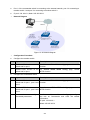
1
TL-SL5428E
24-Port 10/100Mbps + 4-Port Gigabit
L2 Managed Switch
Rev: 1.0.2
1910010340
COPYRIGHT & TRADEMARKS
Specifications are subject to change without notice.
is a registered trademark of
TP-LINK TECHNOLOGIES CO., LTD. Other brands and product names are trademarks or
registered trademarks of their respective holders.
No part of the specifications may be reproduced in any form or by any means or used to make any
derivative such as translation, transformation, or adaptation without permission from TP-LINK
TECHNOLOGIES CO., LTD. Copyright © 2010 TP-LINK TECHNOLOGIES CO., LTD. All rights
reserved.
http://www.tp-link.com
FCC STATEMENT
This equipment has been tested and found to comply with the limits for a Class A digital device,
pursuant to part 15 of the FCC Rules. These limits are designed to provide reasonable protection
against harmful interference when the equipment is operated in a commercial environment. This
equipment generates, uses, and can radiate radio frequency energy and, if not installed and used
in accordance with the instruction manual, may cause harmful interference to radio
communications. Operation of this equipment in a residential area is likely to cause harmful
interference in which case the user will be required to correct the interference at his own expense.
This device complies with part 15 of the FCC Rules. Operation is subject to the following two
conditions:
1)
This device may not cause harmful interference.
2)
This device must accept any interference received, including interference that may cause
undesired operation.
Any changes or modifications not expressly approved by the party responsible for compliance
could void the user’s authority to operate the equipment.
CE Mark Warning
This is a class A product. In a domestic environment, this product may cause radio interference, in
which case the user may be required to take adequate measures.
SAFETY NOTICES
Caution:
Do not use this product near water, for example, in a wet basement or near a swimming pool.
Avoid using this product during an electrical storm. There may be a remote risk of electric shock
from lightning.
III
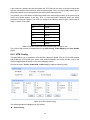
CONTENTS
Package Contents ..........................................................................................................................1
Chapter 1 About this Guide...........................................................................................................2
1.1
Intended Readers .........................................................................................................2
1.2
Conventions..................................................................................................................2
1.3
Overview of This Guide ................................................................................................2
Chapter 2 Introduction ..................................................................................................................6
2.1
Overview of the Switch .................................................................................................6
2.2
Main Features...............................................................................................................6
2.3
Appearance Description ...............................................................................................7
2.3.1 Front Panel ........................................................................................................7
2.3.2 Rear Panel .........................................................................................................8
Chapter 3 Installation ....................................................................................................................9
3.1
Precautions...................................................................................................................9
3.2
Installation.....................................................................................................................9
3.2.1 Desktop Installation..........................................................................................10
3.2.2 Rack Installation...............................................................................................10
3.3
Connect to Ground ..................................................................................................... 11
Chapter 4 Connection .................................................................................................................14
4.1
Ethernet Ports.............................................................................................................14
4.2
SFP Ports ...................................................................................................................14
4.3
Console Port ...............................................................................................................15
4.4
Power On....................................................................................................................16
Chapter 5 Login to the Switch.....................................................................................................17
5.1
Login...........................................................................................................................17
5.2
Configuration ..............................................................................................................17
Chapter 6 System .......................................................................................................................19
6.1
System Info.................................................................................................................19
6.1.1 System Summary.............................................................................................19
6.1.2 Device Description ...........................................................................................21
6.1.3 System Time ....................................................................................................22
6.1.4 System IP.........................................................................................................23
6.2
User Manage ..............................................................................................................24
6.2.1 User Table........................................................................................................24
6.2.2 User Config ......................................................................................................24
6.3
System Tools ..............................................................................................................26
6.3.1 Config Restore .................................................................................................26
IV
6.3.2 Config Backup..................................................................................................26
6.3.3 Firmware Upgrade ...........................................................................................27
6.3.4 System Reboot ................................................................................................28
6.3.5 System Reset...................................................................................................28
6.4
Access Security ..........................................................................................................28
6.4.1 Access Control.................................................................................................28
6.4.2 SSL Config .......................................................................................................30
6.4.3 SSH Config ......................................................................................................31
Chapter 7 Switching....................................................................................................................37
7.1
Port .............................................................................................................................37
7.1.1 Port Config .......................................................................................................37
7.1.2 Port Mirror ........................................................................................................38
7.1.3 Port Security ....................................................................................................40
7.2
LAG ............................................................................................................................41
7.2.1 LAG Table ........................................................................................................42
7.2.2 Static LAG ........................................................................................................43
7.2.3 LACP Config ....................................................................................................44
7.3
Traffic Monitor .............................................................................................................46
7.3.1 Traffic Summary...............................................................................................46
7.3.2 Traffic Statistics ................................................................................................47
7.4
MAC Address..............................................................................................................48
7.4.1 Address Table ..................................................................................................49
7.4.2 Static Address ..................................................................................................51
7.4.3 Dynamic Address .............................................................................................52
7.4.4 Filtering Address ..............................................................................................54
Chapter 8 VLAN..........................................................................................................................56
8.1
802.1Q VLAN..............................................................................................................57
8.1.1 VLAN Config ....................................................................................................59
8.1.2 Port Config .......................................................................................................61
8.2
MAC VLAN .................................................................................................................63
8.2.1 MAC VLAN.......................................................................................................63
8.2.2 Port Enable ......................................................................................................64
8.3
Protocol VLAN ............................................................................................................65
8.3.1 Protocol VLAN .................................................................................................66
8.3.2 Protocol Template ............................................................................................66
8.3.3 Port Enable ......................................................................................................67
8.4
VLAN VPN..................................................................................................................68
V
8.4.1 VPN Config ......................................................................................................69
8.4.2 VLAN Mapping.................................................................................................70
8.4.3 Port Enable ......................................................................................................71
8.5
GVRP .........................................................................................................................72
Chapter 9 Spanning Tree ............................................................................................................76
9.1
STP Config .................................................................................................................81
9.1.1 STP Config.......................................................................................................81
9.1.2 STP Summary..................................................................................................83
9.2
Port Config..................................................................................................................84
9.3
MSTP Instance ...........................................................................................................86
9.3.1 Region Config ..................................................................................................86
9.3.2 Instance Config ................................................................................................87
9.3.3 Instance Port Config.........................................................................................88
9.4
STP Security...............................................................................................................90
9.4.1 Port Protect ......................................................................................................90
9.4.2 TC Protect........................................................................................................93
9.5
Application Example for STP Function .......................................................................94
Chapter 10 Multicast.....................................................................................................................98
10.1
IGMP Snooping ........................................................................................................100
10.1.1 Snooping Config ..........................................................................................101
10.1.2 Port Config ...................................................................................................102
10.1.3 VLAN Config ................................................................................................103
10.1.4 Multicast VLAN ............................................................................................105
10.2
Multicast IP ...............................................................................................................108
10.2.1 Multicast IP Table .........................................................................................109
10.2.2 Static Multicast IP.........................................................................................109
10.3
Multicast Filter........................................................................................................... 110
10.3.1 IP-Range...................................................................................................... 111
10.3.2 Port Filter ..................................................................................................... 112
10.4
Packet Statistics........................................................................................................ 113
Chapter 11 QoS.......................................................................................................................... 115
11.1
DiffServ ..................................................................................................................... 118
11.1.1 Port Priority .................................................................................................. 118
11.1.2 Schedule Mode ............................................................................................ 119
11.1.3 802.1P Priority .............................................................................................120
11.1.4 DSCP Priority...............................................................................................121
11.2
Bandwidth Control ....................................................................................................123
VI
11.2.1 Rate Limit.....................................................................................................123
11.2.2 Storm Control ...............................................................................................124
11.3
Voice VLAN ..............................................................................................................125
11.3.1 Global Config ...............................................................................................127
11.3.2 Port Config ...................................................................................................128
11.3.3 OUI Config ...................................................................................................129
Chapter 12 ACL ..........................................................................................................................131
12.1
Time-Range ..............................................................................................................131
12.1.1 Time-Range Summary .................................................................................131
12.1.2 Time-Range Create......................................................................................132
12.1.3 Holiday Config..............................................................................................133
12.2
ACL Config ...............................................................................................................133
12.2.1 ACL Summary..............................................................................................134
12.2.2 ACL Create ..................................................................................................134
12.2.3 MAC ACL .....................................................................................................135
12.2.4 Standard-IP ACL ..........................................................................................136
12.2.5 Extend-IP ACL .............................................................................................137
12.3
Policy Config.............................................................................................................138
12.3.1 Policy Summary ...........................................................................................138
12.3.2 Policy Create................................................................................................139
12.3.3 Action Create ...............................................................................................139
12.4
Policy Binding ...........................................................................................................141
12.4.1 Binding Table ...............................................................................................141
12.4.2 Port Binding .................................................................................................141
12.4.3 VLAN Binding...............................................................................................142
Chapter 13 Network Security ......................................................................................................146
13.1
IP-MAC Binding ........................................................................................................146
13.1.1 Binding Table ...............................................................................................146
13.1.2 Manual Binding ............................................................................................147
13.1.3 ARP Scanning..............................................................................................149
13.1.4 DHCP Snooping...........................................................................................150
13.2
ARP Inspection .........................................................................................................156
13.2.1 ARP Detect ..................................................................................................160
13.2.2 ARP Defend .................................................................................................161
13.2.3 ARP Statistics ..............................................................................................162
13.3
IP Source Guard .......................................................................................................163
13.4
DoS Defend ..............................................................................................................164
VII
13.4.1 DoS Defend .................................................................................................165
13.4.2 DoS Detect...................................................................................................166
13.5
802.1X ......................................................................................................................167
13.5.1 Global Config ...............................................................................................171
13.5.2 Port Config ...................................................................................................173
13.5.3 Radius Server ..............................................................................................174
Chapter 14 SNMP.......................................................................................................................176
14.1
SNMP Config ............................................................................................................178
14.1.1 Global Config ...............................................................................................178
14.1.2 SNMP View..................................................................................................179
14.1.3 SNMP Group................................................................................................180
14.1.4 SNMP User ..................................................................................................181
14.1.5 SNMP Community .......................................................................................183
14.2
Notification................................................................................................................185
14.3
RMON.......................................................................................................................187
14.3.1 History Control .............................................................................................188
14.3.2 Event Config ................................................................................................188
14.3.3 Alarm Config ................................................................................................189
Chapter 15 Cluster......................................................................................................................192
15.1
NDP ..........................................................................................................................193
15.1.1 Neighbor Info ...............................................................................................193
15.1.2 NDP Summary .............................................................................................194
15.1.3 NDP Config ..................................................................................................196
15.2
NTDP........................................................................................................................197
15.2.1 Device Table ................................................................................................197
15.2.2 NTDP Summary...........................................................................................198
15.2.3 NTDP Config................................................................................................200
15.3
Cluster ......................................................................................................................201
15.3.1 Cluster Summary .........................................................................................201
15.3.2 Cluster Config ..............................................................................................204
15.3.3 Member Config ............................................................................................206
15.3.4 Cluster Topology ..........................................................................................207
15.4
Application Example for Cluster Function .................................................................209
Chapter 16 Maintenance ............................................................................................................212
16.1
System Monitor.........................................................................................................212
16.1.1 CPU Monitor ................................................................................................212
16.1.2 Memory Monitor ...........................................................................................213
VIII
16.2
Log............................................................................................................................214
16.2.1 Log Table .....................................................................................................215
16.2.2 Local Log .....................................................................................................215
16.2.3 Remote Log .................................................................................................216
16.2.4 Backup Log ..................................................................................................217
16.3
Device Diagnose.......................................................................................................218
16.3.1 Cable Test ....................................................................................................218
16.3.2 Loopback .....................................................................................................219
16.4
Network Diagnose ....................................................................................................219
16.4.1 Ping..............................................................................................................219
16.4.2 Tracert..........................................................................................................220
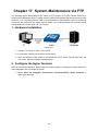
Chapter 17 System Maintenance via FTP ..................................................................................222
Appendix A: Specifications .........................................................................................................227
Appendix B: Configuring the PCs ...............................................................................................228
Appendix C: 802.1X Client Software ..........................................................................................231
Appendix D: Glossary.................................................................................................................239
IX
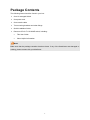
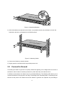
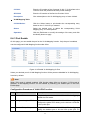
Package Contents
The following items should be found in your box:
¾
One L2 managed Switch
¾
One power cord
¾
One console cable
¾
Two mounting brackets and other fittings
¾
Quick Installation Guide
¾
Resource CD for TL-SL5428E switch, including:
•
This User Guide
•
Other Helpful Information
Note:
Make sure that the package contains the above items. If any of the listed items are damaged or
missing, please contact with your distributor.
1
Chapter 1 About this Guide
This User Guide contains information for setup and management of TL-SL5428E switch. Please
read this guide carefully before operation.
1.1 Intended Readers
This Guide is intended for network managers familiar with IT concepts and network terminologies.
1.2 Conventions
In this Guide the following conventions are used:
¾
The switch or TL-SL5428E mentioned in this Guide stands for TL-SL5428E 24-Port
10/100Mbps + 4-Port Gigabit L2 Managed Switch without any explanation.
¾
Menu Name→Submenu Name→Tab page indicates the menu structure. System→System
Info→System Summary means the System Summary page under the System Info menu
option that is located under the System menu.
¾
Bold font indicates a button, a toolbar icon, menu or menu item.
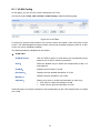
Symbols in this Guide:
Symbol
Description
Note:
Ignoring this type of note might result in a malfunction or damage to the
device.
Tips:
This format indicates important information that helps you make better use
of your device.
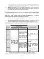
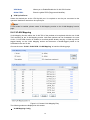
1.3 Overview of This Guide
Chapter
Introduction
Chapter 1 About This Guide
Introduces the guide structure and conventions.
Chapter 2 Introduction
Introduces the features,
TL-SL5428E switch.
Chapter 3 Installation
Introduces how to install the switch.
Chapter 4 Connection
Introduces how to connect the switch..
Chapter 5 Login to the Switch
Introduces how to log on to TL-SL5428E Web management page.
2
application
and
appearance
of
Chapter
Introduction
Chapter 6 System
This module is used to configure system properties of the switch.
Here mainly introduces:
z System Info: Configure the description, system time and network
parameters of the switch.
z User Manage: Configure the user name and password for users
to log on to the Web management page with a certain access
level.
z System Tools: Manage the configuration file of the switch.
z Access Security: Provide different security measures for the
login to enhance the configuration management security.
Chapter 7 Switching
This module is used to configure basic functions of the switch. Here
mainly introduces:
z Port: Configure the basic features for the port.
z LAG: Configure Link Aggregation Group. LAG is to combine a
number of ports together to make a single high-bandwidth data
path.
z Traffic Monitor: Monitor the traffic of each port
z MAC Address: Configure the address table of the switch.
Chapter 8 VLAN
This module is used to configure VLANs to control broadcast in
LANs. Here mainly introduces:
z 802.1Q VLAN: Configure port-based VLAN.
z MAC VLAN: Configure MAC-based VLAN without changing the
802.1Q VLAN configuration.
z Protocol VLAN: Create VLANs in application layer to make some
special data transmitted in the specified VLAN.
z VLAN VPN: VLAN VPN allows the packets with VLAN tags of
private networks to be encapsulated with VLAN tags of public
networks at the network access terminal of the Internet Service
Provider.
z GVRP: GVRP allows the switch to automatically add or remove
the VLANs via the dynamic VLAN registration information and
propagate the local VLAN registration information to other
switches, without having to individually configure each VLAN.
Chapter 9 Spanning Tree
This module is used to configure spanning tree function of the
switch. Here mainly introduces:
z STP Config: Configure and view the global settings of spanning
tree function.
z Port Config: Configure CIST parameters of ports.
z MSTP Instance: Configure MSTP instances.
z STP Security: Configure protection function to prevent devices
from any malicious attack against STP features.
3
Chapter
Introduction
Chapter 10 Multicast
This module is used to configure multicast function of the switch.
Here mainly introduces:
z IGMP Snooping: Configure global parameters of IGMP Snooping
function, port properties, VLAN and multicast VLAN.
z Multicast IP: Configure multicast IP table.
z Multicast Filter: Configure multicast filter feature to restrict users
ordering multicast programs.
z Packet Statistics: View the multicast data traffic on each port of
the switch, which facilitates you to monitor the IGMP messages
in the network.
Chapter 11 QoS
This module is used to configure QoS function to provide different
quality of service for various network applications and
requirements. Here mainly introduces:
z DiffServ: Configure priorities, port priority, 802.1P priority and
DSCP priority.
z Bandwidth Control: Configure rate limit feature to control the
traffic rate on each port; configure storm control feature to filter
broadcast, multicast and UL frame in the network.
z Voice VLAN: Configure voice VLAN to transmit voice data
stream within the specified VLAN so as to ensure the
transmission priority of voice data stream and voice quality.
Chapter 12 ACL
This module is used to configure match rules and process policies
of packets to filter packets in order to control the access of the
illegal users to the network. Here mainly introduces:
z Time-Range: Configure the effective time for ACL rules.
z ACL Config: ACL rules.
z Policy Config: Configure operation policies.
z Policy Binding: Bind the policy to a port/VLAN to take its effect on
a specific port/VLAN.
Chapter 13 Network Security
This module is used to configure the multiple protection measures
for the network security. Here mainly introduces:
z IP-MAC Binding: Bind the IP address, MAC address, VLAN ID
and the connected Port number of the Host together.
z ARP Inspection: Configure ARP inspection feature to prevent the
network from ARP attacks.
z IP Source Guard: Configure IP source guard feature to filter IP
packets in the LAN.
z DoS Defend: Configure DoS defend feature to prevent DoS
attack.
z 802.1X: Configure common access control mechanism for LAN
ports to solve mainly authentication and security problems.
4
Chapter
Introduction
Chapter 14 SNMP
This module is used to configure SNMP function to provide a
management frame to monitor and maintain the network devices.
Here mainly introduces:
z SNMP Config: Configure global settings of SNMP function.
z Notification: Configure notification function for the management
station to monitor and process the events.
z RMON: Configure RMON function to monitor network more
efficiently.
Chapter 15 Cluster
This module is used to configure cluster function to central manage
the scattered devices in the network. Here mainly introduces:
z NDP: Configure NDP function to get the information of the directly
connected neighbor devices.
z NTDP: Configure NTDP function for the commander switch to
collect NDP information.
z Cluster: Configure cluster function to establish and maintain
cluster.
Chapter 16 Maintenance
This module is used to assemble the commonly used system tools
to manage the switch. Here mainly introduces:
z System Monitor: Monitor the memory and CPU of the switch.
z Log: View configuration parameters on the switch.
z Cable Test: Test the connection status of the cable connected to
the switch.
z Loopback: Test if the port of the switch and the connected device
are available.
z Network Diagnose: Test if the destination is reachable and the
account of router hops from the switch to the destination.
Chapter 17 System
Maintenance via FTP
Introduces how to download firmware of the switch via FTP
function.
Appendix A Specifications
Lists the glossary used in this manual.
Appendix B Configure the PCs
Introduces how to configure the PCs.
Appendix C 802.1X Client
Software
Introduces how to use 802.1X Client Software provided for
authentication.
Appendix D Glossary
Lists the glossary used in this manual.
Return to CONTENTS
5
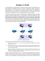
Chapter 2 Introduction
Thanks for choosing the TL-SL5428E 24-Port 10/100Mbps + 4-Port Gigabit L2 Managed Switch!
2.1 Overview of the Switch
Designed for workgroups and departments, TL-SL5428E from TP-Link provides wire-speed
performance and full set of layer 2 management features. It provides a variety of service features
and multiple powerful functions with high security.
The EIA-standardized framework and smart configuration capacity can provide flexible solutions
for a variable scale of networks. ACL, 802.1x, IP Source Guard and Dynamic ARP Inspection
provide robust security strategy. QoS and IGMP snooping/filtering optimize voice and video
application. Link aggregation (LACP) increases aggregated bandwidth, optimizing the transport of
business critical data. SNMP, RMON, WEB/CLI/Telnet Log-in bring abundant management
policies. TL-SL5428E Switch integrates multiple functions with excellent performance, and is
friendly to manage, which can fully meet the need of the users demanding higher networking
performance.
2.2 Main Features
•
Resiliency and Availability
+ Link aggregation (LACP) increases aggregated bandwidth, optimizing the transport of
business critical data.
+ IEEE 802.1s Multiple Spanning Tree provides high link availability in multiple VLAN
environments.
+ Multicast snooping automatically prevents flooding of IP multicast traffic.
+ Root Guard protects root bridge from malicious attack or configuration mistakes
•
Layer 2 Switching
+ GVRP (GARP VLAN Registration Protocol) allows automatic learning and dynamic
assignment of VLANs.
+ Supports 255 active VLAN groups and 4K VLAN IDs.
•
Quality of Service
+ Supports L2/L3 granular CoS with 4 priority queues per port.
+ Rate limiting confines the traffic flow accurately according to the preset value.
•
Security
+ Supports multiple industry standard user authentication methods such as 802.1x, RADIUS.
+ IP Source Guard prevents IP spoofing attacks.
+ Dynamic ARP Inspection blocks ARP packets from unauthorized hosts, preventing
man-in-the-middle attacks.
+ L2/L3/L4 Access Control Lists restrict untrusted access to the protected resource.
+ Provides SSHv1/v2, SSL 2.0/3.0 and TLS v1 for access encryption.
•
Manageability
+ IP Clustering provides high scalability and easy Single-IP-Management.
6
+ Supports Telnet, CLI, SNMP v1/v2c/v3, RMON and web access.
+ Port Mirroring enables monitoring selected ingress/egress traffic.
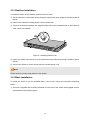
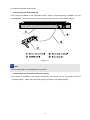
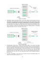
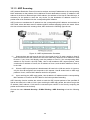
2.3 Appearance Description
2.3.1 Front Panel
Figure 2-1 Front Panel
The following parts are located on the front panel of the Switch:
¾ 10/100Mbps Ports: Designed to connect to the device with a bandwidth of 10Mbps or
100Mbps. Each has a corresponding 10/100Mbps LED.
¾ 10/100/1000Mbps Ports: Designed to connect to the device with a bandwidth of 10Mbps,
100Mbps or 1000Mbps. Each has a corresponding 1000Mbps LED.
¾ SFP Ports: Designed to install the SFP module. SFP1 shares the same LED with Port 27 and
SFP shares the same LED with Port 28.
¾ Console Port: Designed to connect with the serial port of a computer or terminal for monitoring
and configuring the Switch.
¾ LEDs
Name
Status
On
PWR
SYS
Flashing
Indication
Power is on.
Power supply is abnormal.
Off
Power is off or power supply is abnormal.
On
The Switch is working abnormally.
Flashing
The Switch is working normally.
Off
The Switch is working abnormally.
On
A device is linked to the corresponding port.
10/100Mb
Flashing
ps
Green
The linked device is running at 100Mbps.
Yellow
The linked device is running at 10Mbps.
On
Data is being transmitted or received.
A device is linked to the corresponding port.
1000Mbp
Flashing
Data is being transmitted or received.
s
Green
The linked device is running at 1000Mbps.
Yellow
The linked device is running at 10/100Mbps.
7
2.3.2 Rear Panel
The rear panel of TL-SL5428E features a power socket and a Grounding Terminal (marked
with ).
Figure 2-2 Rear Panel
¾ Grounding Terminal: TL-SL5428E already comes with Lightning Protection Mechanism. You
can also ground the Switch through the PE (Protecting Earth) cable of AC cord or with Ground
Cable. For detail information, please refer to section 2.3 Connect to Ground.
¾ AC Power Socket: Connect the female connector of the power cord here, and the male
connector to the AC power outlet. Please make sure the voltage of the power supply meets the
requirement of the input voltage (100-240V~ 50/60Hz 0.6A).
Return to CONTENTS
8
Chapter 3 Installation
3.1 Precautions
To ensure a long-term and stable performance of the Switch, please pay attention to the following
before the installation.
1) Safety Requirements
• Before cleaning the Switch, cut off the power supply. Do not clean it by the waterish cloth,
and never use any other liquid cleaning method.
• Take waterproof measures during storage, transportation and operation of the equipment.
• Use only the power cord provided with the Switch.
• Make sure the voltage of the power supply meets the requirement of the input voltage of the
Switch.
• Do not push any objects into the openings of the Switch.
• Ensure the vent hole is well ventilated and unblocked.
• Do not open or remove the cover of the Switch.
2) Location Requirements
When you choose a location for the Switch, please follow these guidelines:
• Install the Switch on a flat and stable surface that can support the entire weight of the
Switch with all fittings.
• Locate the Switch far from strong electromagnetic field generators (such as motors),
vibration, dust, and direct exposure to sunlight.
• To ensure adequate air flow around the Switch. At least 10 cm (4 inches) of space at the
front and rear of the Switch is needed for ventilation.
• Make sure that the Switch will be accessible and that the cables can be easily connected.
• Position the Switch away from water and moisture sources, be sure to provide an
acceptable temperature and humidity operating environment.
3.2 Installation
This Switch can be either installed on the standard 19-inch mountable rack or located on the
desktop.
Note:
Please unplug the power cord before installing or removing the Switch.
9
3.2.1 Desktop Installation
To install the Switch on the desktop, please follow the steps:
1) Set the Switch on a flat surface strong enough to support the entire weight of the Switch with all
fittings.
2) Remove the adhesive backing papers from the rubber feet.
3) Turnover the Switch and attach the supplied rubber feet to the recessed areas on the bottom at
each corner of the Switch.
Figure 3-1 Attaching Rubber Feet
4) Upturn the Switch and connect it to the network devices while keep enough ventilation space
around.
5) Connect the Switch to power source with the provided power cord.
Note:
Please avoid any heavy thing placed on the Switch.
3.2.2 Rack Installation
To install the Switch in an EIA standard-sized, 19-inch rack, follow the instructions described
below:
1) Secure the supplied rack-mounting brackets to each side of the Switch with supplied screws,
as illustrated in the following figure.
10
Figure 3-2 Attaching Brackets
2) After the brackets are attached to the Switch, use suitable screws (not provided) to secure the
brackets to the rack, as illustrated in the following figure.
Figure 3-3 Mounting Switch
3) Connect the Switch to network devices.
4) Supply power to the Switch with the provided power cord.
3.3 Connect to Ground
Connecting the Switch to ground is to quickly release the lightning over-voltage and over-current of
the Switch, which is also a necessary measure to protect the body from electric shock.
In different environments, the Switch may be grounded differently. The following will instruct you to
connect the Switch to the ground in two ways, connecting to the Grounding Bar or connecting to the
Ground via the power cord. Please connect the Switch to ground in the optimum way according to
11
your specific operation environment.
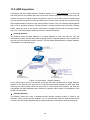
•
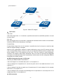
Connecting to the Grounding Bar
If the Switch is installed in the Equipment Room, where a Grounding Bar is available, you are
recommended to connect the Switch to the Grounding Bar as shown in the following figure.
Figure 3-4
Tips:
The Grounding Bar is not provided with our product.
•
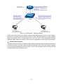
Connecting to the Ground via the power supply
If the Switch is installed in the normal environment, the Switch can be grounded via the PE
(Protecting Earth)cable of the AC power supply as shown in the following figure.
12
Figure 3-5
* The figure is to illustrate the application and principle. The power plug you get from the package
and the socket in your situation will comply with the regulation in your country, so they may differ
from the figure above.
Tips:
If you intend to connect the Switch to the ground via the PE (Protecting Earth) cable of AC power
cord, please make sure the PE (Protecting Earth) cable in the electrical outlet is well grounded in
advance.
Return to CONTENTS
13
Chapter 4 Connection
4.1 Ethernet Ports
The Switch has 24 10/100Mbps and 4 10/100/1000Mbps auto-negotiating, auto-crossover
Ethernet ports, which can be directly connected to the network devices by RJ45 cable as the
following figure shown.
Figure 4-1 Connecting the RJ45 Port
4.2 SFP Ports
The Switch features two SFP (Small Form-Factor Pluggable) transceiver slots that are shared with
two associated 1000Base-T RJ45 ports. If an SFP transceiver (purchased separately) is installed
in a slot and has a valid link on the port, the associated RJ45 port will be disabled and cannot be
used.
Tips:
TL-SL5428E supports 100/1000Base-FX SFP module at full-duplex mode.
14
Figure 4-2 Inserting SFP Module
4.3 Console Port
The Switch features a console interface for configuring the Switch using CLI (Command Line
Interface).
Note:
The serial port of the computer doesn’t support plug-and-play feature, please make sure the
Switch is powered off before connecting the console cable to the computer.
Connect the console port of the Switch and your computer with a console cable as shown in
Figure 4-3.
Figure 4-3 Connecting the Console Port
15
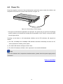
4.4 Power On
Plug in the negative connector of the provided power cord into the power socket of the Switch, and
the positive connector into a power outlet as shown in Figure 4-4.
Figure 4-4 Connecting to Power Supply
* The figure is to illustrate the application and principle. The power plug you get from the package
and the socket in your situation will comply with the regulation in your country, so they may differ
from the figure above.
Powering on the Switch, it will automatically initialize and its LED indicators will respond as
follows:
1) All of the 10/100Mbps and 1000Mbps LED indicators will flash momentarily and then turn off,
which represents a resetting of the system.
2) The PWR LED indicator will light on all the time.
3) The SYS LED indicator will flash, which represents a successful initialization.
Tips:
If the LED indicators don’t respond as described above, please check the power supply and its
connection.
Return to CONTENTS
16
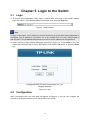
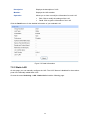
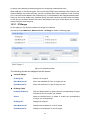
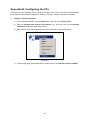
Chapter 5 Login to the Switch
5.1 Login
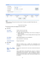
1) To access the configuration utility, open a web-browser and type in the default address
http://192.168.0.1 in the address field of the browser, then press the Enter key.
Figure 5-1 Web-browser
Tips:
To log in to the Switch, the IP address of your PC should be set in the same subnet addresses of
the Switch. The IP address is 192.168.0.x ("x" is any number from 2 to 254), Subnet Mask is
255.255.255.0. For the detailed instructions as to how to do this, please refer to Appendix B.
2) After a moment, a login window will appear, as shown in Figure 5-2. Enter admin for the User
Name and Password, both in lower case letters. Then click the OK button or press the Enter
key.
Figure 5-2 Login
5.2 Configuration
After a successful login, the main page will appear as Figure 5-3, and you can configure the
function by clicking the setup menu on the left side of the screen.
17
Figure 5-3 Main Setup-Menu
Note:
Clicking Apply can only make the new configurations effective before the switch is rebooted. If
you want to keep the configurations effective even the switch is rebooted, please click Saving
Config. You are suggested to click Saving Config before cutting off the power or rebooting the
switch to avoid losing the new configurations.
Return to CONTENTS
18
Chapter 6 System
The System module is mainly for system configuration of the switch, including four submenus:
System Info, User Manage, System Tools and Access Security.
6.1 System Info
The System Info, mainly for basic properties configuration, can be implemented on System
Summary, Device Description, System Time and System IP pages.
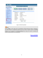
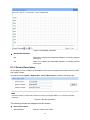
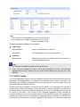
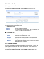
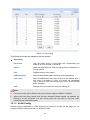
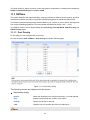
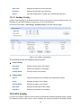
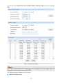
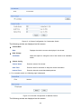
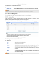
6.1.1 System Summary
On this page you can view the port connection status and the system information.
The port status diagram shows the working status of 24 10/100Mbps RJ45 ports, 4
10/100/1000Mbps RJ45 ports and 2 SFP ports of the switch. The ports labeled as numbers are
10/100Mbps ports; the ports labeled as G are 10/100/1000Mbps ports; the ports labeled as SFP
are SFP ports.
Choose the menu System→System Info→System Summary to load the following page.
1.0.1 Build 20100226 Rel.38288
Figure 6-1 System Summary
¾
Port Status
Indicates the 100Mbps port is not connected to a device.
Indicates the 100Mbps port is at the speed of 100Mbps.
Indicates the 100Mbps port is at the speed of 10Mbps.
19
Indicates the 1000Mbps port is not connected to a device.
Indicates the 1000Mbps port is at the speed of 1000Mbps.
Indicates the 1000Mbps port is at the speed of 10Mbps or 100Mbps.
Indicates the SFP port is not connected to a device.
Indicates the SFP port is at the speed of 1000Mbps.
Indicates the SFP port is at the speed of 100Mbps.
When the cursor moves on the port, the detailed information of the port will be displayed.
Figure 6-2 Port Information
¾
Port Info
Port:
Displays the port number of the switch.
Type:
Displays the type of the port.
Rate:
Displays the maximum transmission rate of the port.
Status:
Displays the connection status of the port.
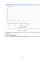
Click a port to display the bandwidth utilization on this port. The actual rate divided by theoretical
maximum rate is the bandwidth utilization. Figure 1-3 displays the bandwidth utilization monitored
every four seconds. Monitoring the bandwidth utilization on each port facilitates you to monitor the
network traffic and analyze the network abnormities.
20
Figure 6-3 Bandwidth Utilization
¾
Bandwidth Utilization
Rx:
Select Rx to display the bandwidth utilization of receiving packets
on this port.
Tx:
Select Tx to display the bandwidth utilization of sending packets
on this port.
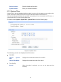
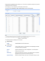
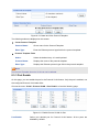
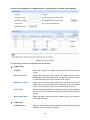
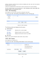
6.1.2 Device Description
On this page you can configure the description of the switch, including device name, device location
and system contact.
Choose the menu System→System Info→Device Description to load the following page.
Figure 6-4 Device Description
The following entries are displayed on this screen:
¾
Device Description
Device Name:
Enter the name of the switch.
21
Device Location:
Enter the location of the switch.
System Contact:
Enter your contact information.
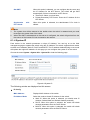
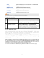
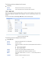
6.1.3 System Time
System Time is the time displayed while the switch is running. On this page you can configure the
system time and the settings here will be used for other time-based functions like ACL.
You can manually set the system time, get GMT automatically if it has connected to a NTP server or
synchronize with PC’s clock as the system time.
Choose the menu System→System Info→System Time to load the following page.
Figure 6-5 System Time
The following entries are displayed on this screen:
¾
Time Info
Current
Date:
System
Current Time Mode:
¾
Displays the current date and time of the switch.
Displays the current time mode of the switch.
Time Config
Manual:
When this option is selected, you can set the date and time
manually.
22
Get GMT:
When this option is selected, you can configure the time zone and
the IP Address for the NTP Server. The switch will get GMT
automatically if it has connected to a NTP Server.
z
z
Synchronize
PC’S Clock:
with
Time Zone: Select your local time.
Primary/Secondary NTP Server: Enter the IP Address for the
NTP Server.
When this option is selected, the administrator PC’s clock is
utilized.
Note:
1.
The system time will be restored to the default when the switch is restarted and you need
reconfigure the system time of the switch.
2.
When Get GMT is selected and no time server is configured, the switch will get time from the
time server of the Internet if it has connected to the Internet.
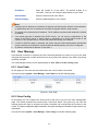
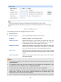
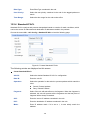
6.1.4 System IP
Each device in the network possesses a unique IP Address. You can log on to the Web
management page to operate the switch using this IP Address. The switch supports three modes
to obtain an IP address: Static IP, DHCP and BOOTP. The IP address obtained using a new mode
will replace the original IP address. On this page you can configure the system IP of the switch.
Choose the menu System→System Info→System IP to load the following page.
Figure 6-6 System IP
The following entries are displayed on this screen:
¾
IP Config
MAC Address:
Displays MAC Address of the switch.
IP Address Mode:
Select the mode to obtain IP Address for the switch.
z
z
z
Static IP: When this option is selected, you should enter IP
Address, Subnet Mask and Default Gateway manually.
DHCP: When this option is selected, the switch will obtain
network parameters from the DHCP Server.
BOOTP: When this option is selected, the switch will obtain
network parameters from the BOOTP Server.
23
IP Address:
Enter the system IP of the switch. The default system IP is
192.168.0.1 and you can change it appropriate to your needs.
Subnet Mask:
Enter the subnet mask of the switch.
Default Gateway:
Enter the default gateway of the switch.
Note:
1.
Changing the IP address to a different IP segment will interrupt the network communication,
so please keep the new IP address in the same IP segment with the local network.
2.
The switch only possesses an IP address. The IP address configured will replace the original
IP address.
3.
If the switch gets the IP address from DHCP server, you can see the configuration of the
switch in the DHCP server; if DHCP option is selected but no DHCP server exists in the
network, a few minutes later, the switch will restore the setting to the default.
4.
If DHCP or BOOTP option is selected, the switch will gets network parameters dynamically
from the Internet, so IP address, subnet mask and default gateway can not be configured.
5.
By default, the default IP address is 192.168.0.1.
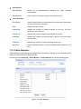
6.2 User Manage
User Manage functions to configure the user name and password for users to log on to the Web
management page with a certain access level so as to protect the settings of the switch from being
randomly changed.
The User Manage function can be implemented on User Table and User Config pages.
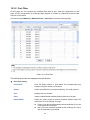
6.2.1 User Table
On this page you can view the information about the current users of the switch.
Choose the menu System→User Manage→User Table to load the following page.
Figure 6-7 User Table
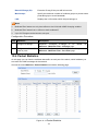
6.2.2 User Config
On this page you can configure the access level of the user to log on to the Web management
page. The switch provides two access levels: Guest and Admin. The guest only can view the
settings without the right to configure the switch; the admin can configure all the functions of the
switch. The Web management pages contained in this guide are subject to the admin’s login without any
explanation.
Choose the menu System→User Manage→User Config to load the following page.
24
Figure 6-8 User Config
The following entries are displayed on this screen:
¾
User Info
User Name:
Create a name for users’ login.
Access Level:
Select the access level to login.
z
z
¾
Admin: Admin can edit, modify and view all the settings of
different functions.
Guest: Guest only can view the settings without the right to edit
and modify.
User Status:
Select Enable/Disable the user configuration.
Password:
Type a password for users’ login.
Confirm Password:
Retype the password.
User Table
Select:
Select the desired entry to delete the corresponding user
information. It is multi-optional The current user information can’t
be deleted.
User
ID,
Name,
Access Level and
status:
Displays the current user ID, user name, access level and user
status.
Operation:
Click the Edit button of the desired entry, and you can edit the
corresponding user information. After modifying the settings,
please click the Modify button to make the modification effective.
Access level and user status of the current user information can’t
be modified.
25
6.3 System Tools
The System Tools function, allowing you to manage the configuration file of the switch, can be
implemented on Config Restore, Config Backup, Firmware Upgrade, System Reboot and
System Reset pages.
6.3.1 Config Restore
On this page you can upload a backup configuration file to restore your switch to this previous
configuration.
Choose the menu System→System Tools→Config Restore to load the following page.
Figure 6-9 Config Restore
The following entries are displayed on this screen:
¾
Config Restore
Restore Config:
Click the Restore Config button to restore the backup
configuration file. It will take effect after the switch automatically
reboots.
Note:
1.
It will take a few minutes to restore the configuration. Please wait without any operation.
2.
To avoid any damage, please don’t power down the switch while being restored.
3.
After being restored, the current settings of the switch will be lost. Wrong uploaded
configuration file may cause the switch unmanaged.
6.3.2 Config Backup
On this page you can download the current configuration and save it as a file to your computer for
your future configuration restore.
Choose the menu System→System Tools→Config Backup to load the following page.
26
Figure 6-10 Config Backup
The following entries are displayed on this screen:
¾
Config Backup
Backup Config:
Click the Backup Config button to save the current configuration
as a file to your computer. You are suggested to take this measure
before upgrading.
Note:
It will take a few minutes to backup the configuration. Please wait without any operation.
6.3.3 Firmware Upgrade
The switch system can be upgraded via the Web management page. To upgrade the system is to
get more functions and better performance. Go to http://www.tp-link.com to download the updated
firmware.
Choose the menu System→System Tools→Firmware Upgrade to load the following page.
Figure 6-11 Firmware Upgrade
Note:
1.
Don’t interrupt the upgrade.
2.
Please select the proper software version matching with your hardware to upgrade.
27
3.
To avoid damage, please don't turn off the device while upgrading.
4.
After upgrading, the device will reboot automatically.
5.
You are suggested to backup the configuration before upgrading.
6.3.4 System Reboot
On this page you can reboot the switch and return to the login page. Please save the current
configuration before rebooting to avoid loosing the configuration unsaved
Choose the menu System→System Tools→System Reboot to load the following page.
Figure 6-12 System Reboot
Note:
To avoid damage, please don't turn off the device while rebooting.
6.3.5 System Reset
On this page you can reset the switch to the default. All the settings will be cleared after the switch
is reset.
Choose the menu System→System Tools→System Reset to load the following page.
Figure 6-13 System Reset
Note:
After the system is reset, the switch will be reset to the default and all the settings will be cleared.
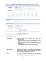
6.4 Access Security
Access Security provides different security measures for the remote login so as to enhance the
configuration management security. It can be implemented on Access Control, SSL Config and
SSH Config pages.
6.4.1 Access Control
On this page you can control the users logging on to the Web management page to enhance the
configuration management security. The definitions of Admin and Guest refer to 1.2 User Manage
28
Choose the menu System→Access Security→Access Control to load the following page.
Figure 6-14 Access Control
The following entries are displayed on this screen:
¾
Access Control Config
Control Mode:
Select the control mode for users to log on to the Web
management page.
z
z
z
IP-based: Select this option to limit the IP-range of the users for
login.
MAC-based: Select this option to limit the MAC Address of the
users for login.
Port-based: Select this option to limit the ports for login.
IP Address&Mask
These fields can be available for configuration only when IP-based
mode is selected. Only the current host and the users within the
IP-range you set here are allowed for login.
MAC Address:
The field can be available for configuration only when MAC-based
mode is selected. Only the current host and the user with this
MAC Address you set here are allowed for login.
Port:
The field can be available for configuration only when Port-based
mode is selected. Only the current host and the users connected
to these ports you set here are allowed for login.
29
¾
Session Config
Session Timeout:
¾
If you do nothing with the Web management page within the
timeout time, the system will log out automatically. If you want to
reconfigure, please login again.
Access User Number
Number Control;
Select Enable/Disable the Number Control function.
Admin Number:
Enter the maximum number of the users logging on to the Web
management page as Admin.
Guest Number:
Enter the maximum number of the users logging on to the Web
management page as Guest.
6.4.2 SSL Config
SSL (Secure Sockets Layer), a security protocol, is to provide a secure connection for the
application layer protocol (e.g. HTTP) communication based on TCP. SSL is widely used to secure
the data transmission between the Web browser and servers. It is mainly applied through
ecommerce and online banking.
SSL mainly provides the following services:
1.
Authenticate the users and the servers based on the certificates to ensure the data are
transmitted to the correct users and servers;
2.
Encrypt the data transmission to prevent the data being intercepted;
3.
Maintain the integrality of the data to prevent the data being altered in the transmission.
Adopting asymmetrical encryption technology, SSL uses key pair to encrypt/decrypt information. A
key pair refers to a public key (contained in the certificate) and its corresponding private key. By
default the switch has a certificate (self-signed certificate) and a corresponding private key. The
Certificate/Key Download function enables the user to replace the default key pair.
After SSL is effective, you can log on to the Web management page via https://192.168.0.1. For
the first time you use HTTPS connection to log into the switch with the default certificate, you will
be prompted that “The security certificate presented by this website was not issued by a trusted
certificate authority” or “Certificate Errors”. Please add this certificate to trusted certificates or
continue to this website.
On this page you can configure the SSL function.
Choose the menu System→Access Security→SSL Config to load the following page.
30
Figure 6-15 SSL Config
The following entries are displayed on this screen:
¾
Global Config
SSL:
¾
Certificate Download
Certificate File:
¾
Select Enable/Disable the SSL function on the switch.
Select the desired certificate to download to the switch. The
certificate must be BASE64 encoded.
Key Download
Key File:
Select the desired SSL Key to download to the switch. The key
must be BASE64 encoded.
Note:
1.
The SSL certificate and key downloaded must match each other; otherwise the HTTPS
connection will not work.
2.
The SSL certificate and key downloaded will not take effect until the switch is rebooted.
3.
To establish a secured connection using https, please enter https:// into the URL field of the
browser.
4.
It may take more time for https connection than that for http connection, because https
connection involves authentication, encryption and decryption etc.
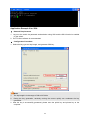
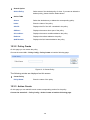
6.4.3 SSH Config
As stipulated by IFTF (Internet Engineering Task Force), SSH (Secure Shell) is a security protocol
established on application and transport layers. SSH-encrypted-connection is similar to a telnet
connection, but essentially the old telnet remote management method is not safe, because the
password and data transmitted with plain-text can be easily intercepted. SSH can provide
information security and powerful authentication when you log on to the switch remotely through
an insecure network environment. It can encrypt all the transmission data and prevent the
31
information in a remote management being leaked.
Comprising server and client, SSH has two versions, V1 and V2 which are not compatible with
each other. In the communication, SSH server and client can auto-negotiate the SSH version and
the encryption algorithm. After getting a successful negotiation, the client sends authentication
request to the server for login, and then the two can communicate with each other after successful
authentication. This switch supports SSH server and you can log on to the switch via SSH
connection using SSH client software.
SSH key can be downloaded into the switch. If the key is successfully downloaded, the certificate
authentication will be preferred for SSH access to the switch.
Choose the menu System→Access Seurity→SSH Config to load the following page.
Figure 6-16 SSH Config
The following entries are displayed on this screen:
¾
¾
Global Config
SSH:
Select Enable/Disable SSH function.
Protocol V1:
Select Enable/Disable SSH V1 to be the supported protocol.
Protocol V2:
Select Enable/Disable SSH V2 to be the supported protocol.
Idle Timeout:
Specify the idle timeout time. The system will automatically
release the connection when the time is up. The default time is
500 seconds.
Max Connect:
Specify the maximum number of the connections to the SSH
server. No new connection will be established when the number of
the connections reaches the maximum number you set. The
default value is 5.
Key Download
32
Key Type:
Select the type of SSH Key to download. The switch supports
three types: SSH-1 RSA, SSH-2 RSA and SSH-2 DSA.
Key File:
Select the desired key file to download.
Download:
Click the Download button to down the desired key file to the
switch.
Note:
1.
Please ensure the key length of the downloaded file is in the range of 256 to 3072 bits.
2.
After the Key File is downloaded, the user’s original key of the same type will be replaced.
The wrong uploaded file will result in the SSH access to the switch via Password
authentication.
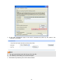
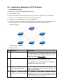
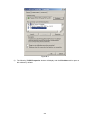
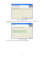
Application Example 1 for SSH:
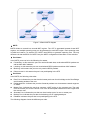
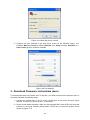
¾
Network Requirements
1. Log on to the switch via password authentication using SSH and the SSH function is enabled
on the switch.
2. PuTTY client software is recommended.
¾
Configuration Procedure
1. Open the software to log on to the interface of PuTTY. Enter the IP address of the switch into
Host Name field; keep the default value 22 in the Port field; select SSH as the Connection
type.
2. Click the Open button in the above figure to log on to the switch. Enter the login user name and
password, and then you can continue to configure the switch.
33
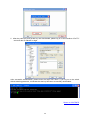
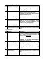
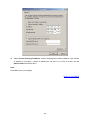
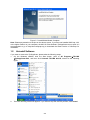
Application Example 2 for SSH:
¾
Network Requirements
1. Log on to the switch via password authentication using SSH and the SSH function is enabled
on the switch.
2. PuTTY client software is recommended.
¾
Configuration Procedure
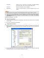
1. Select the key type and key length, and generate SSH key.
Note:
1.
The key length is in the range of 256 to 3072 bits.
2.
During the key generation, randomly moving the mouse quickly can accelerate the key
generation.
2. After the key is successfully generated, please save the public key and private key to the
computer.
34
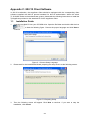
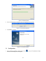
3. On the Web management page of the switch, download the public key file saved in the
computer to the switch.
Note:
1.
The key type should accord with the type of the key file.
2.
The SSH key downloading can not be interrupted.
4. Download the private key file to SSH client software.
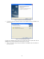
35
5. After the public key and private key are downloaded, please log on to the interface of PuTTY
and enter the IP address for login.
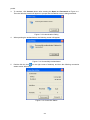
After successful authentication, please enter the login user name. If you log on to the switch
without entering password, it indicates that the key has been successfully downloaded.
Return to CONTENTS
36
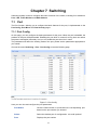
Chapter 7 Switching
Switching module is used to configure the basic functions of the switch, including four submenus:
Port, LAG, Traffic Monitor and MAC Address.
7.1 Port
The Port function, allowing you to configure the basic features for the port, is implemented on the
Port Config, Port Mirror and Port Security pages.
7.1.1 Port Config
On this page, you can configure the basic parameters for the ports. When the port is disabled, the
packets on the port will be discarded. Disabling the port which is vacant for a long time can reduce
the power consumption effectively. And you can enable the port when it is in need.
The parameters will affect the working mode of the port, please set the parameters appropriate to
your needs.
Choose the menu Switching→Port→Port Config to load the following page.
Figure 7-1 Port Config
Here you can view and configure the port parameters.
Port Select:
Click the Select button to quick-select the corresponding port
based on the port number you entered.
Select:
Select the desired port for configuration. It is multi-optional.
Port:
Displays the port number.
37
Description:
Give a description to the port for identification.
Status:
Allows you to Enable/Disable the port. When Enable is
selected, the port can forward the packets normally.
Speed and Duplex:
Select the Speed and Duplex mode for the port. The device
connected to the switch should be in the same Speed and
Duplex mode with the switch. When “Auto” is selected, the
Speed and Duplex mode will be determined by
auto-negotiation.
Flow Control:
Allows you to Enable/Disable the Flow Control feature. When
Flow Control is enabled, the switch can synchronize the speed
with its peer to avoid the packet loss caused by congestion.
LAG:
Displays the LAG number which the port belongs to.
Note:
1.
The switch can not be managed through the disabled port. Please enable the port which is
used to manage the switch.
2.
The parameters of the port members in a LAG should be set as the same.
7.1.2 Port Mirror
Port Mirror, the packets obtaining technology, functions to forward copies of packets from
one/multiple ports (mirrored port) to a specific port (mirroring port). Usually, the mirroring port is
connected to a data diagnose device, which is used to analyze the mirrored packets for monitoring
and troubleshooting the network.
Choose the menu Switching→Port→Port Mirror to load the following page.
38
Figure 7-2 Mirroring Port
The following entries are displayed on this screen.
¾
Mirroring Port
Mirroring Port:
¾
Select a port from the pull-down list as the mirroring port. When
disable is selected, the Port Mirror feature will be disabled.
Mirrored Port
Port Select:
Click the Select button to quick-select the corresponding port
based on the port number you entered.
Select:
Select the desired port as a mirrored port. It is multi-optional.
Port:
Displays the port number.
Ingress:
Select Enable/Disable the Ingress feature. When the Ingress is
enabled, the incoming packets received by the mirrored port will be
copied to the mirroring port.
Egress:
Select Enable/Disable the Egress feature. When the Egress is
enabled, the outgoing packets sent by the mirrored port will be
copied to the mirroring port.
LAG:
Displays the LAG number which the port belongs to. The LAG
member can not be selected as the mirrored port or mirroring port.
39
Note:
1.
The LAG member can not be selected as the mirrored port or mirroring port.
2.
A port can not be set as the mirrored port and the mirroring port simultaneously.
3.
The Port Mirror function can take effect span the multiple VLANs.
7.1.3 Port Security
MAC Address Table maintains the mapping relationship between the port and the MAC address of
the connected device, which is the base of the packet forwarding. The capacity of MAC Address
Table is fixed. MAC Address Attack is the attack method that the attacker takes to obtain the
network information illegally. The attacker uses tools to generate the cheating MAC address and
quickly occupy the MAC Address Table. When the MAC Address Table is full, the switch will
broadcast the packets to all the ports. At this moment, the attacker can obtain the network
information via various sniffers and attacks. When the MAC Address Table is full, the packets
traffic will flood to all the ports, which results in overload, lower speed, packets drop and even
breakdown of the system.
Port Security is to protect the switch from the malicious MAC Address Attack by limiting the
maximum number of MAC addresses that can be learned on the port. The port with Port Security
feature enabled will learn the MAC address dynamically. When the learned MAC address number
reaches the maximum, the port will stop learning. Thereafter, the other devices with the MAC
address unlearned can not access to the network via this port.
Choose the menu Switching→Port→Port Security to load the following page.
Figure 7-3 Port Security
The following entries are displayed on this screen:
¾
Port Security
40
Select:
Select the desired port for Port Security configuration. It is
multi-optional.
Port:
Displays the port number.
Max Learned MAC:
Specify the maximum number of MAC addresses that can be
learned on the port.
Learned Num:
Displays the number of MAC addresses that have been learned
on the port.
Learn Mode:
Select the Learn Mode for the port.
Status:
•
Dynamic: When Dynamic mode is selected, the learned
MAC address will be deleted automatically after the aging
time.
•
Static: When Static mode is selected, the learned MAC
address will be out of the influence of the aging time and
can only be deleted manually. The learned entries will be
cleared after the switch is rebooted.
•
Permanent: When Permanent mode is selected, the
learned MAC address will be out of the influence of the
aging time and can only be deleted manually. The learned
entries will be saved even the switch is rebooted.
Select Enable/Disable the Port Security feature for the port.
Note:
1.
The Port Security function is disabled for the LAG port member. Only the port is removed from
the LAG, will the Port Security function be available for the port.
2.
The Port Security function is disabled when the 802.1X function is enabled.
7.2 LAG
LAG (Link Aggregation Group) is to combine a number of ports together to make a single
high-bandwidth data path, so as to implement the traffic load sharing among the member ports in
the group and to enhance the connection reliability.
For the member ports in an aggregation group, their basic configuration must be the same. The
basic configuration includes STP, QoS, GVRP, VLAN, port attributes, MAC Address Learning
mode and other associated settings. The further explains are following:
z
If the ports, which are enabled for the GVRP, 802.1Q VLAN, Voice VLAN, STP, QoS, DHCP
Snooping and Port Configuration (Speed and Duplex, Flow Control), are in a LAG, their
configurations should be the same.
z
The ports, which are enabled for the Port Security, Port Mirror, MAC Address Filtering,
Static MAC Address Binding, 802.1X Authentication and IP Source Guard, can not be
added to the LAG.
z
It’s not suggested to add the ports with ARP Inspection and DoS Defend enabled to the
LAG.
41
If the LAG is needed, you are suggested to configure the LAG function here before configuring the
other functions for the member ports.
Tips:
1.
Calculate the bandwidth for a LAG: If a LAG consists of the four ports in the speed of
1000Mbps Full Duplex, the whole bandwidth of the LAG is up to 8000Mbps (2000Mbps * 4)
because the bandwidth of each member port is 2000Mbps counting the up-linked speed of
1000Mbps and the down-linked speed of 1000Mbps.
2.
The traffic load of the LAG will be balanced among the ports according to the Aggregate
Arithmetic. If the connections of one or several ports are broken, the traffic of these ports will
be transmitted on the normal ports, so as to guarantee the connection reliability.
Depending on different aggregation modes, aggregation groups fall into two types: Static LAG
and LACP Config. The LAG function is implemented on the LAG Table, Static LAG and LACP
Config configuration pages.
7.2.1 LAG Table
On this page, you can view the information of the current LAG of the switch.
Choose the menu Switching→LAG→LAG Table to load the following page.
Figure 7-4 LAG Table
The following entries are displayed on this screen:
¾
Global Config
Aggregate Arithmetic:
Select the applied scope of Aggregate Arithmetic, which
results in choosing a port to transfer the packets.
• SRC MAC + DST MAC: When this option is selected,
the Aggregate Arithmetic will apply to the source and
destination MAC addresses of the packets.
• SRC IP + DST IP: When this option is selected, the
Aggregate Arithmetic will apply to the source and
destination IP addresses of the packets.
¾
LAG Table
Select:
Select the desired LAG. It is multi-optional.
Group Number:
Displays the LAG number here.
42
Description:
Displays the description of LAG.
Member:
Displays the LAG member.
Operation:
Allows you to view or modify the information for each LAG.
•
Edit: Click to modify the settings of the LAG.
•
Detail: Click to get the information of the LAG.
Click the Detail button for the detailed information of your selected LAG.
Figure 7-5 Detail Information
7.2.2 Static LAG
On this page, you can manually configure the LAG. The LACP feature is disabled for the member
ports of the manually added Static LAG.
Choose the menu Switching→LAG→Static LAG to load the following page.
43
Figure 7-6 Manually Config
The following entries are displayed on this screen:
¾
¾
LAG Config
Group Number:
Select a Group Number for the LAG.
Description:
Give a description to the LAG for identification.
LAG Table
Member Port:
Select the port as the LAG member. Clearing all the ports of
the LAG will delete this LAG.
Tips:
1.
The LAG can be deleted by clearing its all member ports.
2.
A port can only be added to a LAG. If a port is the member of a LAG or is dynamically
aggregated as the LACP member, the port number will be displayed in gray and can not be
selected.
7.2.3 LACP Config
LACP (Link Aggregation Control Protocol) is defined in IEEE802.3ad and enables the dynamic link
aggregation and disaggregation by exchanging LACP packets with its partner. The switch can
dynamically group similarly configured ports into a single logical link, which will highly extend the
bandwidth and flexibly balance the load.
With the LACP feature enabled, the port will notify its partner of the aggregation ID (consist of
System Priority, system MAC address and the Admin Key). A dynamic aggregation group will only
be formed between ports having the same aggregation ID. Up to fourteen aggregation groups can
be formed by the switch. If the amount of the configured aggregation groups exceeds the
maximum number, the group with smaller System Priority takes the priority to be aggregated.
Similarly, up to eight ports can be selected in an aggregation group. Therefore, the port also has
the priority to be selected as the dynamic aggregation group member. The port with smaller Port
44
Priority will be considered as the preferred one. If the two port priorities are equal; the port with
smaller port number is preferred.
On this page, you can configure the LACP feature of the switch.
Choose the menu Switching→LAG→LACP Config to load the following page.
Figure 7-7 LACP Config
The following entries are displayed on this screen:
¾
Global Config
LACP:
¾
Enable/Disable the LACP feature here.
LACP Config
Port Select:
Click the Select button to quick-select the corresponding port based
on the port number you entered.
Select:
Select the desired port for LACP configuration. It is multi-optional.
Port:
Displays the port number.
Admin Key:
Specify an Admin Key for the port. The member ports in a dynamic
aggregation group must have the same Admin Key.
System Priority:
Specify a System Priority for the port. The System Priority and the
45
Admin Key constitute the aggregation ID. A dynamic aggregation
group will only be formed between ports having the same
aggregation ID.
Port Priority:
Specify a Port Priority for the port. This value determines the priority
of the port to be selected as the dynamic aggregation group
member. The port with smaller Port Priority will be considered as the
preferred one. If the two port priorities are equal; the port with
smaller port number is preferred.
Status:
Enable/Disable the LACP feature for your selected port.
LAG:
Displays the LAG number which the port belongs to.
7.3 Traffic Monitor
The Traffic Monitor function, monitoring the traffic of each port, is implemented on the Traffic
Summary and Traffic Statistics pages.
7.3.1 Traffic Summary
Traffic Summary screen displays the traffic information of each port, which facilitates you to
monitor the traffic and analyze the network abnormity.
Choose the menu Switching→Traffic Monitor→Traffic Summary to load the following page.
Figure 7-8 Traffic Summary
The following entries are displayed on this screen:
46
¾
¾
Auto Refresh
Auto Refresh:
Allows you to Enable/Disable refreshing the Traffic Summary
automatically.
Refresh Rate:
Enter a value in seconds to specify the refresh interval.
Traffic Summary
Port Select:
Click the Select button to quick-select the corresponding port based
on the port number you entered.
Port:
Displays the port number.
Packets Rx:
Displays the number of packets received on the port. The error
packets are not counted in.
Packets Tx:
Displays the number of packets transmitted on the port.
Octets Rx:
Displays the number of octets received on the port. The error octets
are counted in.
Octets Tx:
Displays the number of octets transmitted on the port.
Statistics:
Click the Statistics button to view the detailed traffic statistics of the
port.
7.3.2 Traffic Statistics
Traffic Statistics screen displays the detailed traffic information of each port, which facilitates you to
monitor the traffic and locate faults promptly.
Choose the menu Switching→Traffic Monitor→Traffic Statistics to load the following page.
Figure 7-9 Traffic Statistics
47
The following entries are displayed on this screen:
¾
¾
Auto Refresh
Auto Refresh:
Allows you to Enable/Disable refreshing the Traffic Summary
automatically.
Refresh Rate:
Enter a value in seconds to specify the refresh interval.
Statistics
Port:
Enter a port number and click the Select button to view the traffic
statistics of the corresponding port.
Received:
Displays the details of the packets received on the port.
Sent:
Displays the details of the packets transmitted on the port.
Broadcast:
Displays the number of good broadcast packets received or
transmitted on the port. The error frames are not counted in.
Multicast:
Displays the number of good multicast packets received or
transmitted on the port. The error frames are not counted in.
Unicast:
Displays the number of good unicast packets received or
transmitted on the port. The error frames are not counted in.
Alignment Errors:
Displays the number of the received packets that have a bad
Frame Check Sequence (FCS) with a non-integral octet
(Alignment Error). The length of the packet is between 64 bytes
and 1518 bytes.
UndersizePkts:
Displays the number of the received packets (excluding error
packets) that are less than 64 bytes long.
Pkts64Octets:
Displays the number of the received packets (including error
packets) that are 64 bytes long.
Pkts65to127Octets:
Displays the number of the received packets (including error
packets) that are between 65 and 127 bytes long.
Pkts128to255Octets:
Displays the number of the received packets (including error
packets) that are between 128 and 255 bytes long.
Pkts256to511Octets:
Displays the number of the received packets (including error
packets) that are between 256 and 511 bytes long.
Pkts512to1023Octets:
Displays the number of the received packets (including error
packets) that are between 512 and 1023 bytes long.
Pkts1024to2044Octets:
Displays the number of the received packets (including error
packets) that are between 1024 and 2044 bytes.
Collisions:
Displays the number of collisions experienced by a port during
packet transmissions.
7.4 MAC Address
The main function of the switch is forwarding the packets to the correct ports based on the
48
destination MAC address of the packets. Address Table contains the port-based MAC address
information, which is the base for the switch to forward packets quickly. The entries in the Address
Table can be updated by auto-learning or configured manually. Most the entries are generated and
updated by auto-learning. In the stable networks, the static MAC address entries can facilitate the
switch to reduce broadcast packets and enhance the efficiency of packets forwarding remarkably.
The address filtering feature allows the switch to filter the undesired packets and forbid its
forwarding so as to improve the network security.
The types and the features of the MAC Address Table are listed as the following:
Type
Configuration Way
Being kept after reboot Relationship between
bound
MAC
Aging out (if the configuration is the
address and the port
saved)
Static
Manually configuring
Address Table
No
Yes
The
bound
MAC
address can not be
learned by the other
ports in the same
VLAN.
Dynamic
Automatically
Address Table learning
Yes
No
The
bound
MAC
address can be learned
by the other ports in the
same VLAN.
Filtering
Manually configuring
Address Table
No
Yes
-
Table 7-1 Types and features of Address Table
This function includes four submenus: Address Table, Static Address, Dynamic Address and
Filtering Address.
7.4.1 Address Table
On this page, you can view all the information of the Address Table.
Choose the menu Switching→MAC Address→Address Table to load the following page.
49
Figure 7-10 Address Table
The following entries are displayed on this screen:
¾
Search Option
MAC Address:
Enter the MAC address of your desired entry.
VLAN ID:
Enter the VLAN ID of your desired entry.
Port:
Select the corresponding port number of your desired entry.
Type:
Select the type of your desired entry.
z
z
z
z
¾
All: This option allows the address table to display all the
address entries.
Static: This option allows the address table to display the static
address entries only.
Dynamic: This option allows the address table to display the
dynamic address entries only.
Filtering: This option allows the address table to display the
filtering address entries only.
Address Table
50
MAC Address:
Displays the MAC address learned by the switch.
VLAN ID:
Displays the corresponding VLAN ID of the MAC address.
Port:
Displays the corresponding Port number of the MAC address.
Type:
Displays the Type of the MAC address.
Aging Status:
Displays the Aging status of the MAC address.
7.4.2 Static Address
The static address table maintains the static address entries which can be added or removed
manually, independent of the aging time. In the stable networks, the static MAC address entries
can facilitate the switch to reduce broadcast packets and remarkably enhance the efficiency of
packets forwarding without learning the address. The static MAC address learned by the port with
Port Security enabled in the static learning mode will be displayed in the Static Address Table.
Choose the menu Switching→MAC Address→Static Address to load the following page.
Figure 7-11 Static Address
The following entries are displayed on this screen:
¾
¾
Create Static Address
MAC Address:
Enter the static MAC Address to be bound.
VLAN ID:
Enter the corresponding VLAN ID of the MAC address.
Port:
Select a port from the pull-down list to be bound.
Search Option
51
Search Option:
¾
Select a Search Option from the pull-down list and click the Search
button to find your desired entry in the Static Address Table.
•
MAC: Enter the MAC address of your desired entry.
•
VLAN ID: Enter the VLAN ID number of your desired entry.
•
Port: Enter the Port number of your desired entry.
Static Address Table
Select:
Select the entry to delete or modify the corresponding port number. It
is multi-optional.
MAC Address:
Displays the static MAC Address.
VLAN ID:
Displays the corresponding VLAN ID of the MAC address.
Port:
Displays the corresponding Port number of the MAC address. Here
you can modify the port number to which the MAC address is bound.
The new port should be in the same VLAN.
Type:
Displays the Type of the MAC address.
Aging Status:
Displays the Aging Status of the MAC address.
Note:
1.
If the corresponding port number of the MAC address is not correct, or the connected port (or
the device) has been changed, the switch can not be forward the packets correctly. Please
reset the static address entry appropriately.
2.
If the MAC address of a device has been added to the Static Address Table, connecting the
device to another port will cause its address not to be recognized dynamically by the switch.
Therefore, please ensure the entries in the Static Address Table are correct and valid.
3.
The MAC address in the Static Address Table can not be added to the Filtering Address Table
or bound to a port dynamically.
4.
This static MAC address bound function is not available if the 802.1X feature is enabled.
7.4.3 Dynamic Address
The dynamic address can be generated by the auto-learning mechanism of the switch. The
Dynamic Address Table can update automatically by auto-learning or aging out the MAC address.
To fully utilize the MAC address table, which has a limited capacity, the switch adopts an aging
mechanism for updating the table. That is, the switch removes the MAC address entries related to
a network device if no packet is received from the device within the aging time.
On this page, you can configure the dynamic MAC address entry.
Choose the menu Switching→MAC Address→Dynamic Address to load the following page.
52
Figure 7-12 Dynamic Address
The following entries are displayed on this screen:
¾
¾
Aging Config
Auto Aging:
Allows you to Enable/Disable the Auto Aging feature.
Aging Time:
Enter the Aging Time for the dynamic address.
Search Option
Search Option:
¾
Select a Search Option from the pull-down list and click the Search
button to find your desired entry in the Dynamic Address Table.
•
MAC: Enter the MAC address of your desired entry.
•
VLAN ID: Enter the VLAN ID number of your desired entry.
•
Port: Enter the Port number of your desired entry.
Dynamic Address Table
53
Select:
Select the entry to delete the dynamic address or to bind the MAC
address to the corresponding port statically. It is multi-optional.
MAC Address:
Displays the dynamic MAC Address.
VLAN ID:
Displays the corresponding VLAN ID of the MAC address.
Port:
Displays the corresponding port number of the MAC address.
Type:
Displays the Type of the MAC address.
Aging Status:
Displays the Aging Status of the MAC address.
Bind:
Click the Bind button to bind the MAC address of your selected entry
to the corresponding port statically.
Tips:
Setting aging time properly helps implement effective MAC address aging. The aging time that is
too long or too short results decreases the performance of the switch. If the aging time is too long,
excessive invalid MAC address entries maintained by the switch may fill up the MAC address table.
This prevents the MAC address table from updating with network changes in time. If the aging time
is too short, the switch may remove valid MAC address entries. This decreases the forwarding
performance of the switch. It is recommended to keep the default value.
7.4.4 Filtering Address
The filtering address is to forbid the undesired packets to be forwarded. The filtering address can
be added or removed manually, independent of the aging time. The filtering MAC address allows
the witch to filter the packets which includes this MAC address as the source address or
destination address, so as to guarantee the network security. The filtering MAC address entries
act on all the ports in the corresponding VLAN.
Choose the menu Switching→MAC Address→Filtering Address to load the following page.
Figure 7-13 Filtering Address
54
The following entries are displayed on this screen:
¾
¾
Create Filtering Address
MAC Address:
Enter the MAC Address to be filtered.
VLAN ID:
Enter the corresponding VLAN ID of the MAC address.
Search Option
Search Option:
¾
Select a Search Option from the pull-down list and click the Search
button to find your desired entry in the Filtering Address Table.
•
MAC: Enter the MAC address of your desired entry.
•
VLAN ID: Enter the VLAN ID number of your desired entry.
Filtering Address Table
Select:
Select the entry to delete the corresponding filtering address. It is
multi-optional.
MAC Address:
Displays the filtering MAC Address.
VLAN ID:
Displays the corresponding VLAN ID.
Port:
Here the symbol “__” indicates no specified port.
Type:
Displays the Type of the MAC address.
Aging Status:
Displays the Aging Status of the MAC address.
Note:
1.
The MAC address in the Filtering Address Table can not be added to the Static Address Table
or bound to a port dynamically.
2.
This MAC address filtering function is not available if the 802.1X feature is enabled.
Return to CONTENTS
55
Chapter 8 VLAN
The traditional Ethernet is a data network communication technology basing on CSMA/CD (Carrier
Sense Multiple Access/Collision Detect) via shared communication medium. Through the
traditional Ethernet, the overfull hosts in LAN will result in serious collision, flooding broadcasts,
poor performance or even breakdown of the Internet. Though connecting the LANs through
switches can avoid the serious collision, the flooding broadcasts can not be prevented, which will
occupy plenty of bandwidth resources, causing potential serious security problems.
A Virtual Local Area Network (VLAN) is a network topology configured according to a logical
scheme rather than the physical layout. The VLAN technology is developed for switches to control
broadcast in LANs. By creating VLANs in a physical LAN, you can divide the LAN into multiple
logical LANs, each of which has a broadcast domain of its own. Hosts in the same VLAN
communicate with one another as if they are in a LAN. However, hosts in different VLANs cannot
communicate with one another directly. Therefore, broadcast packets are limited in a VLAN. Hosts
in the same VLAN communicate with one another via Ethernet whereas hosts in different VLANs
communicate with one another through the Internet devices such as Router, the Lay3 Switch and
etc. The following figure illustrates a VLAN implementation.
Figure 8-1 VLAN implementation
Compared with the traditional Ethernet, VLAN enjoys the following advantages.
(1) Broadcasts are confined to VLANs. This decreases bandwidth utilization and improves
network performance.
(2) Network security is improved. VLANs cannot communicate with one another directly. That
is, a host in a VLAN cannot access resources in another VLAN directly, unless routers or
Layer 3 switches are used.
(3) Network configuration workload for the host is reduced. VLAN can be used to group
specific hosts. When the physical position of a host changes within the range of the VLAN,
you need not change its network configuration.
A VLAN can span across multiple switches, or even routers. This enables hosts in a VLAN to be
dispersed in a looser way. That is, hosts in a VLAN can belong to different physical network
segment. This switch supports three ways, namely, 802.1Q VLAN, MAC VLAN and Protocol VLAN,
to classify VLANs. VLAN tags in the packets are necessary for the switch to identify packets of
56
different VLANs. The switch can analyze the received untagged packets on the port and match the
packets with the MAC VLAN, Protocol VLAN and 802.1Q VLAN in turn. If a packet is matched, the
switch will add a corresponding VLAN tag to it and forward it in the corresponding VLAN.
8.1 802.1Q VLAN
VLAN tags in the packets are necessary for the switch to identify packets of different VLANs. The
switch works at the data link layer in OSI model and it can identify the data link layer encapsulation
of the packet only, so you can add the VLAN tag field into the data link layer encapsulation for
identification.
In 1999, IEEE issues the IEEE 802.1Q protocol to standardize VLAN implementation, defining the
structure of VLAN-tagged packets. IEEE 802.1Q protocol defines that a 4-byte VLAN tag is
encapsulated after the destination MAC address and source MAC address to show the information
about VLAN.
As shown in the following figure, a VLAN tag contains four fields, including TPID (Tag Protocol
Identifier), Priority, CFI (Canonical Format Indicator), and VLAN ID.
Figure 8-2 Format of VLAN Tag
(1) TPID: TPID is a 16-bit field, indicating that this data frame is VLAN-tagged. By default, it is
0x8100 in H3C series Ethernet switches.
(2) Priority: Priority is a 3-bit field, referring to 802.1p priority. Refer to section “QoS & QoS
profile” for details.
(3) CFI: CFI is a 1-bit field, indicating whether the MAC address is encapsulated in the
standard format in different transmission media. This field is not described in detail in this
chapter.
(4) VLAN ID: VLAN ID is a 12-bit field, indicating the ID of the VLAN to which this packet
belongs. It is in the range of 0 to 4,095. Generally, 0 and 4,095 is not used, so the field is in
the range of 1 to 4,094.
VLAN ID identifies the VLAN to which a packet belongs. When the switch receives an
un-VLAN-tagged packet, it will encapsulate a VLAN tag with the default VLAN ID of the inbound
port for the packet, and the packet will be assigned to the default VLAN of the inbound port for
transmission.
In this User Guide, the tagged packet refers to the packet with VLAN tag whereas the untagged
packet refers to the packet without VLAN tag, and the priority-tagged packet refers to the packet
with VLAN tag whose VLAN ID is 0.
¾
Link Types of ports
When creating the 802.1Q VLAN, you should set the link type for the port according to its
connected device. The link types of port including the following three types:
(1) ACCESS: The ACCESS port can be added in a single VLAN, and the egress rule of the
port is UNTAG. The PVID is same as the current VLAN ID. If the ACCESS port is added to
another VLAN, it will be removed from the current VLAN automatically.
(2) TRUNK: The TRUNK port can be added in multiple VLANs, and the egress rule of the port
57
is TAG. The TRUNK port is generally used to connect the cascaded network devices for it
can receive and forward the packets of multiple VLANs. When the packets are forwarded
by the TRUNK port, its VLAN tag will not be changed.
(3) GENERAL: The GENERAL port can be added in multiple VLANs and set various egress
rules according to the different VLANs. The default egress rule is UNTAG. The PVID can
be set as the VID number of any VLAN the port belongs to.
¾
PVID
PVID (Port Vlan ID) is the default VID of the port. When the switch receives an un-VLAN-tagged
packet, it will add a VLAN tag to the packet according to the PVID of its received port and forward
the packets.
When creating VLANs, the PVID of each port, indicating the default VLAN to which the port
belongs, is an important parameter with the following two purposes:
(1) When the switch receives an un-VLAN-tagged packet, it will add a VLAN tag to the packet
according to the PVID of its received port
(2) PVID determines the default broadcast domain of the port, i.e. when the port receives UL
packets or broadcast packets, the port will broadcast the packets in its default VLAN.
Different packets, tagged or untagged, will be processed in different ways, after being received by
ports of different link types, which is illustrated in the following table.
Receiving Packets
Port Type
Forwarding Packets
Untagged Packets
If the VID of packet is
the same as the PVID
of the port, the packet
will be received.
Access
Trunk
General
Tagged Packets
When
untagged
packets
are
received, the port
will add the default
VLAN tag, i.e. the
PVID of the ingress
port, to the packets.
If the VID of packet is
not the same as the
PVID of the port, the
packet will be dropped.
The
packet
will
be
forwarded after removing its
VLAN tag.
The
packet
will
be
forwarded with its current
VLAN tag.
If the VID of packet is
allowed by the port, the
packet will be received.
If the VID of packet is
forbidden by the port,
the packet will be
dropped.
If the egress rule of port is
TAG, the packet will be
forwarded with its current
VLAN tag.
If the egress rule of port is
UNTAG, the packet will be
forwarded after removing its
VLAN tag.
Table 8-1 Relationship between Port Types and VLAN Packets Processing
IEEE 802.1Q VLAN function is implemented on the VLAN Config and Port Config pages.
58
8.1.1 VLAN Config
On this page, you can view the current created 802.1Q VLAN.
Choose the menu VLAN→802.1Q VLAN→VLAN Config to load the following page.
Figure 8-3 VLAN Table
To ensure the normal communication of the factory switch, the default VLAN of all ports is set to
VLAN1. The Web Management Page of switch can only be accessed through the ports in VLAN1.
VLAN1 can not be modified or deleted.
The following entries are displayed on this screen:
¾
VLAN Table
VLAN ID Select:
Click the Select button to quick-select the corresponding entry
based on the VLAN ID number you entered.
Select:
Select the desired entry to delete the corresponding VLAN. It is
multi-optional.
VLAN ID:
Displays the ID number of VLAN.
Description:
Displays the user-defined description of VLAN.
Members:
Displays the port members in the VLAN.
Operation:
Allows you to view or modify the information for each entry.
•
Edit: Click to modify the settings of VLAN.
•
Detail: Click to get the information of VLAN.
Click Edit button to modify the settings of the corresponding VLAN. Click Create button to create a
new VLAN.
59
Figure 8-4 Create or Modify 802.1Q VLAN
The following entries are displayed on this screen:
¾
¾
VLAN Config
VLAN ID:
Enter the ID number of VLAN.
Description:
Give a description to the VLAN for identification.
Check:
Click the Check button to check whether the VLAN ID you entered
is valid or not.
VLAN Members
Port Select:
Click the Select button to quick-select the corresponding entry
based on the port number you entered.
Select:
Select the desired port to be a member of VLAN or leave it blank.
It's multi-optional.
Port:
Displays the port number.
Link Type:
Displays the Link Type of the port. It can be reset on Port Config
screen.
60
Egress Rule:
LAG:
Select the Egress Rule for the VLAN port member. The default
egress rule is UNTAG.
•
TAG: All packets forwarded by the port are tagged. The
packets contain VLAN information.
•
UNTAG: Packets forwarded by the port
Displays the LAG to which the port belongs.
8.1.2 Port Config
Before creating the 802.1Q VLAN, please acquaint yourself with all the devices connected to the
switch in order to configure the ports properly.
Choose the menu VLAN→802.1Q VLAN→Port Config to load the following page.
Figure 8-5 802.1Q VLAN – Port Config
The following entries are displayed on this screen:
¾
VLAN Port Config
Port Select:
Click the Select button to quick-select the corresponding entry
based on the port number you entered.
Select:
Select the desired port for configuration. It is multi-optional.
Port:
Displays the port number.
61
Select the Link Type from the pull-down list for the port.
Link Type:
•
ACCESS: The ACCESS port can be added in a single VLAN,
and the egress rule of the port is UNTAG. The PVID is same
as the current VLAN ID. If the current VLAN is deleted, the
PVID will be set to 1 by default.
•
TRUNK: The TRUNK port can be added in multiple VLANs,
and the egress rule of the port is TAG. The PVID can be set as
the VID number of any VLAN the port belongs to.
•
GENERAL: The GENERAL port can be added in multiple
VLANs and set various egress rules according to the different
VLANs. The default egress rule is UNTAG. The PVID can be
set as the VID number of any VLAN the port belongs to.
PVID:
Enter the PVID number of the port.
LAG:
Displays the LAG to which the port belongs.
VLAN:
Click the Detail button to view the information of the VLAN to
which the port belongs.
Click the Detail button to view the information of the corresponding VLAN
Figure 8-6 View the Current VLAN of Port
The following entries are displayed on this screen:
VLAN of Port
¾
VLAN ID Select:
Click the Select button to quick-select the corresponding entry
based on the VLAN ID number you entered.
VLAN ID:
Displays the ID number of VLAN.
VLAN Description:
Displays the user-defined description of VLAN.
Operation:
Allows you to remove the port from the current VLAN.
Configuration Procedure:
Step
Operation
Description
1
Set the link type for
port.
Required. On the VLAN→802.1Q VLAN→Port Config page, set
the link type for the port basing on its connected device.
2
Create VLAN.
Required. On the VLAN→802.1Q VLAN→VLAN Config page,
click the Create button to create a VLAN. Enter the VLAN ID and
62
the description for the VLAN. Meanwhile, specify its member
ports.
3
Modify/View VLAN.
Optional. On the VLAN→802.1Q VLAN→VLAN Config page,
click the Edit/Detail button to modify/view the information of the
corresponding VLAN.
4
Delete VLAN
Optional. On the VLAN→802.1Q VLAN→VLAN Config page,
select the desired entry to delete the corresponding VLAN by
clicking the Delete button.
8.2 MAC VLAN
MAC VLAN technology is the way to classify VLANs according to the MAC addresses of Hosts. A
MAC address corresponds to a single VLAN ID. For the device in a MAC VLAN, if its MAC address
is bound to VLAN, the device can be connected to another member port in this VLAN and still
takes its member role effect without changing the configuration of VLAN members.
The packet in MAC VLAN is processed in the following way:
1.
When receiving an untagged packet, the switch matches the packet with the current MAC
VLAN. If the packet is matched, the switch will add a corresponding MAC VLAN tag to it. If no
MAC VLAN is matched, the switch will add a tag to the packet according to the PVID of the
received port. Thus, the packet is assigned automatically to the corresponding VLAN for
transmission.
2.
When receiving tagged packet, the switch will process it basing on the 802.1Q VLAN. If the
received port is the member of the VLAN to which the tagged packet belongs, the packet will
be forwarded normally. Otherwise, the packet will be discarded.
3.
If the MAC address of a Host is classified into 802.1Q VLAN, please set its connected port of
switch to be a member of this 802.1Q VLAN so as to ensure the packets forwarded normally.
8.2.1 MAC VLAN
On this page, you can create MAC VLAN and view the current MAC VLANs in the table.
Choose the menu VLAN→MAC VLAN to load the following page.
Figure 8-7 Create and View MAC VLAN
63
The following entries are displayed on this screen:
VLAN Table
¾
MAC Address:
Enter the MAC address.
Description:
Give a description to the MAC address for identification.
VLAN ID:
Enter the ID number of the MAC VLAN. This VLAN should be one of the
802.1Q VLANs the ingress port belongs to.
MAC VLAN Table
¾
MAC Select:
Click the Select button to quick-select the corresponding entry based on
the MAC address you entered.
Select:
Select the desired entry. It is multi-optional.
MAC Address:
Displays the MAC address.
Description:
Displays the user-defined description of the MAC address.
VLAN ID:
Displays the corresponding VLAN ID of the MAC address.
Operation:
Click the Edit button to modify the settings of the entry. And click the
Modify button to apply your settings.
8.2.2 Port Enable
On this page, you can enable the port for the MAC VLAN feature. Only the port is enabled, can the
configured MAC VLAN take effect.
Choose the menu “VLAN→MAC VLAN→Port Enable” to load the following page.
Figure 8-8 Enable MAC VLAN for Port
Port Enable:
Select your desired port for Protocol VLAN feature. All the ports are
disabled by default.
Configuration Procedure:
Step
Operation
Description
1
Set the link type for
port.
Required. On the VLAN→802.1Q VLAN→Port Config page, set
the link type for the port basing on its connected device.
2
Create VLAN.
Required. On the VLAN→802.1Q VLAN→VLAN Config page,
64
click the Create button to create a VLAN. Enter the VLAN ID and
the description for the VLAN. Meanwhile, specify its member
ports.
3
Create MAC VLAN.
Required. On the VLAN→MAC VLAN page, create the MAC
VLAN. For the device in a MAC VLAN, it’s required to set its
connected port of switch to be a member of this VLAN so as to
ensure the normal communication.
4
Select your desired
ports for MAC VLAN
feature.
Required. On the VLAN→MAC VLAN→Port Enable page,
select and enable the desired ports for MAC VLAN feature.
8.3 Protocol VLAN
Protocol VLAN is another way to classify VLANs basing on network protocol. Protocol VLANs can
be sorted by IP, IPX, DECnet, AppleTalk, Banyan and so on. Through the Protocol VLANs, the
broadcast domain can span over multiple switches and the Host can change its physical position
in the network with its VLAN member role always effective. By creating Protocol VLANs, the
network administrator can manage the network clients basing on their actual applications and
services effectively.
This switch can classify VLANs basing on the common protocol types listed in the following table.
Please create the Protocol VLAN to your actual need.
Protocol Type
Type value
ARP
0x0806
IP
0x0800
MPLS
0x8847/0x8848
IPX
0x8137
IS-IS
0x8000
LACP
0x8809
802.1X
0x888E
Table 8-2 Protocol types in common use
The packet in Protocol VLAN is processed in the following way:
1.
When receiving an untagged packet, the switch matches the packet with the current Protocol
VLAN. If the packet is matched, the switch will add a corresponding Protocol VLAN tag to it. If
no Protocol VLAN is matched, the switch will add a tag to the packet according to the PVID of
the received port. Thus, the packet is assigned automatically to the corresponding VLAN for
transmission.
2.
When receiving tagged packet, the switch will process it basing on the 802.1Q VLAN. If the
received port is the member of the VLAN to which the tagged packet belongs, the packet will
be forwarded normally. Otherwise, the packet will be discarded.
3.
If the Protocol VLAN is created, please set its enabled port to be the member of
corresponding 802.1Q VLAN so as to ensure the packets forwarded normally.
65
8.3.1 Protocol VLAN
On this page, you can create Protocol VLAN and view the information of the current defined
Protocol VLANs.
Choose the menu VLAN→Protocol VLAN→Protocol VLAN to load the following page.
Figure 8-9 Create Protocol VLAN
The following entries are displayed on this screen:
¾
¾
Create Protocol VLAN
Protocol:
Select the defined protocol template.
VLAN ID:
Enter the ID number of the Protocol VLAN. This VLAN should be one
of the 802.1Q VLANs the ingress port belongs to.
Protocol VLAN Table
Select:
Select the desired entry. It is multi-optional.
Protocol:
Displays the protocol template of the VLAN.
Ether Type:
Displays the Ethernet protocol type field in the protocol template.
VLAN ID:
Displays the corresponding VLAN ID of the protocol.
Operation:
Click the Edit button to modify the settings of the entry. And click the
Modify button to apply your settings.
8.3.2 Protocol Template
The Protocol Template should be created before configuring the Protocol VLAN. By default, the
switch has defined the IP Template, ARP Template, RARP Template, etc. You can add more
Protocol Template on this page.
Choose the menu VLAN→Protocol VLAN→Protocol Template to load the following page.
66
Figure 8-10 Create and View Protocol Template
The following entries are displayed on this screen:
¾
¾
Create Protocol Template
Protocol Name:
Give a name for the Protocol Template.
Ether Type:
Enter the Ethernet protocol type field in the protocol template.
Protocol Template Table
Select:
Select the desired entry. It is multi-optional.
Protocol Name:
Displays the name of the protocol template.
Ether Type:
Displays the Ethernet protocol type field in the protocol template.
Note:
The Protocol Template bound to VLAN can not be deleted.
8.3.3 Port Enable
On this page, you can enable the port for the Protocol VLAN feature. Only the port is enabled, can
the configured Protocol VLAN take effect.
Choose the menu “VLAN→Protocol VLAN→Port Enable” to load the following page.
Figure 8-11 Enable Protocol VLAN for Port
Port Enable:
Select your desired port for Protocol VLAN feature. All the ports are
disabled by default.
67
Configuration Procedure:
Step
Operation
Description
1
Set the link type for port.
Required. On the VLAN→802.1Q VLAN→Port Config
page, set the link type for the port basing on its connected
device.
2
Create VLAN.
Required. On the VLAN→802.1Q VLAN→VLAN Config
page, click the Create button to create a VLAN. Enter the
VLAN ID and the description for the VLAN. Meanwhile,
specify its member ports.
3
Create Protocol Template.
Required. On the VLAN→Protocol VLAN→Protocol
Template page, create the Protocol Template before
configuring Protocol VLAN.
4
Select your desired ports for
Protocol VLAN feature.
Required. On the VLAN→Protocol VLAN→Port Enable
page, select and enable the desired ports for Protocol
VLAN feature.
5
Create Protocol VLAN.
Required. On the VLAN→Protocol VLAN→Protocol
VLAN page, select the protocol type and enter the VLAN ID
to create a Protocol VLAN.
6
Modify/View VLAN.
Optional. On the VLAN→Protocol VLAN→Protocol VLAN
page, click the Edit button to modify/view the information of
the corresponding VLAN.
7
Delete VLAN.
Optional. On the VLAN→Protocol VLAN→Protocol VLAN
page, select the desired entry to delete the corresponding
VLAN by clicking the Delete button.
8.4 VLAN VPN
With the increasing application of the Internet, the VPN (Virtual Private Network) technology is
developed and used to establish the private network through the operators’ backbone networks.
VLAN-VPN (Virtual Private Network) function, the implement of a simple and flexible Layer 2 VPN
technology, allows the packets with VLAN tags of private networks to be encapsulated with VLAN
tags of public networks at the network access terminal of the Internet Service Provider. And these
packets will be transmitted with double-tag across the public networks.
The VLAN-VPN function provides you with the following benefits:
(1) Provides simple Layer 2 VPN solutions for small-sized MANs or intranets.
(2) Saves public network VLAN ID resource.
(3) You can have VLAN IDs of your own, which is independent of public network VLAN IDs.
(4) When the network of the Internet Service Provider is upgraded, the user’s network with a
relative independence can still work normally without changing the current configurations.
In addition, the switch supports the feature to adjust the TPID Values of VLAN VPN Packets. TPID
(Tag Protocol Identifier) is a filed of the VLAN tag. IEEE 802.1Q specifies the value of TPID to be
0x8100. This switch adopts the default value of TPID (0x8100) defined by the protocol. Other
manufacturers use other TPID values (such as 0x9100 or 0x9200) in the outer tags of VLAN-VPN
packets. To be compatible with devices coming from other manufacturers, this switch can adjust
the TPID values of VLAN-VPN packets globally. You can configure TPID values by yourself. When
68
a port receives a packet, this port will replace the TPID value in the outer VLAN tag of this packet
with the user-defined value and then send the packet again. Thus, the VLAN-VPN packets sent to
the public network can be recognized by devices of other manufacturers.
The position of the TPID field in an Ethernet packet is the same as the position of the protocol type
field in the packet without VLAN Tag. Thus, to avoid confusion happening when the switch
forwards or receives a packet, you must not configure the following protocol type values listed in
Table 1-1as the TPID value.
Protocol type
Value
ARP
0x0806
IP
0x0800
MPLS
0x8847/0x8848
IPX
0x8137
IS-IS
0x8000
LACP
0x8809
802.1X
0x888E
Table 8-3 Values of Ethernet frame protocol type in common use
This VLAN VPN function is implemented on the VPN Config, VLAN Mapping and Port Enable
pages.
8.4.1 VPN Config
This page allows you to enable the VPN function, adjust the global TPID for VLAN-VPN packets
and enable the VPN up-link port. When VPN mode is enabled, the switch will add a tag to the
received tagged packet basing on the VLAN mapping entries.
Choose the menu “VLAN→VLAN VPN→VPN Config” to load the following page.
Figure 8-12 VPN Global Config
The following entries are displayed on this screen:
¾
Global Config
69
¾
VPN Mode:
Allows you to Enable/Disable the VLAN-VPN function.
Global TPID:
Enter the global TPID (Tag protocol identifier).
VPN Up-link Ports
Select the desired port as the VPN Up-link port. It’s required to set the port connected to the
operators’ backbone networks to be up-link port.
Note:
If VPN mode is enabled, please create VLAN Mapping entries on the VLAN Mapping function
page.
8.4.2 VLAN Mapping
VLAN Mapping function allows the VLAN TAG of the packets to be replaced with the new VLAN
TAG according to the VLAN Mapping entries. And these packets can be forwarded in the new
VLAN. If VLAN VPN function is enabled, a received packet already carrying a VLAN tag will be
tagged basing on the VLAN Mapping entries and becomes a double-tagged packet to be
forwarded in the new VLAN.
Choose the menu “VLAN→VLAN VPN→VLAN Mapping” to load the following page.
Figure 8-13 Create VLAN Mapping Entry
The following entries are displayed on this screen:
¾
VLAN Mapping Config
70
C VLAN:
Enter the ID number of the Customer VLAN. C VLAN refers to the
VLAN to which the packet received by switch belongs.
SP VLAN:
Enter the ID number of the Service Provider VLAN.
Description:
Give a description to the VLAN Mapping entry or leave it blank.
VLAN Mapping Table
¾
C VLAN Select:
Click the Select button to quick-select the corresponding entry
based on the C VLAN ID you entered.
Select:
Select the desired entry to delete the corresponding VLAN
Mapping entry. It is multi-optional.
Operation:
Click the Edit button to modify the settings of the entry and click
the Modify button to apply.
8.4.3 Port Enable
On this page, you can enable the port for the VLAN Mapping function. Only the port is enabled,
can the configured VLAN Mapping function take effect.
Figure 8-14 Enable VLAN Mapping for Port
Select your desired port for VLAN Mapping function. All the ports are disabled for VLAN Mapping
function by default.
Note:
When VPN mode is globally enabled, VPN function takes effect on all ports. If VPN mode is
disabled, VLAN Mapping function can be enabled by selecting your desired port on this Port
Enable page.
Configuration Procedure of VLAN VPN Function:
Step
Operation
Description
1
Enable VPN mode.
Required. On the VLAN→VLAN VPN→VPN Config page,
enable the VPN mode.
2
Configure the global TPID.
Optional. On the VLAN→VLAN VPN→VPN Config page,
configure the global TPID basing on the devices connected
to the up-link port.
3
Set the VPN up-link port.
Required. On the VLAN→VLAN VPN→VPN Config page,
specify the desired port to be the VPN up-link port. It’s
71
required to set the port connected to the backbone
networks to be up-link port.
4
Create
entries.
VLAN
Mapping
Required. On the VLAN→VLAN VPN→VLAN Mapping
page, configure the VLAN Mapping entries basing on the
actual application.
5
Create
SP
Provider) VLAN
(Service
Optional. On the VLAN→802.1Q VLAN page, create the
SP VLAN. For the steps of creating VLAN, please refer to
802.1Q VLAN.
Configuration Procedure of VLAN Mapping Function:
Step
Operation
Description
1
Create
entries.
VLAN
Mapping
Required. On the VLAN→VLAN VPN→VLAN Mapping
page, configure the VLAN Mapping entries basing on the
actual application.
2
Enable
VLAN
function for port.
Mapping
Required. On the VLAN→VLAN VPN→Port Enable page,
enable VLAN Mapping function for the ports.
3
Create
SP
Provider) VLAN
(Service
Optional. On the VLAN→802.1Q VLAN page, create the
SP VLAN. For the steps of creating VLAN, please refer to
802.1Q VLAN.
8.5 GVRP
GVRP (GARP VLAN Registration Protocol) is an implementation of GARP (generic attribute
registration protocol). GVRP allows the switch to automatically add or remove the VLANs via the
dynamic VLAN registration information and propagate the local VLAN registration information to
other switches, without having to individually configure each VLAN.
¾
GARP
GARP provides the mechanism to assist the switch members in LAN to deliver, propagate and
register the information among the members. GARP itself does not work as the entity among the
devices. The application complied with GARP is called GARP implementation, and GVRP is the
implementation of GARP. When GARP is implemented on a port of device, the port is called
GARP entity.
The information exchange between GARP entities is completed by messages. GARP defines the
messages into three types: Join, Leave and LeaveAll.
•
Join Message: When a GARP entity expects other switches to register certain attribute
information of its own, it sends out a Join message. And when receiving the Join message
from the other entity or configuring some attributes statically, the device also sends out a Join
message in order to be registered by the other GARP entities.
•
Leave Message: When a GARP entity expects other switches to deregister certain attribute
information of its own, it sends out a Leave message. And when receiving the Leave message
from the other entity or deregistering some attributes statically, the device also sends out a
Leave message.
•
LeaveAll Message: Once a GARP entity starts up, it starts the LeaveAll timer. After the timer
times out, the GARP entity sends out a LeaveAll message. LeaveAll message is to deregister
72
all the attribute information so as to enable the other GARP entities to re-register attribute
information of their own.
Through message exchange, all the attribute information to be registered can be propagated to all
the switches in the same switched network.
The interval of GARP messages is controlled by timers. GARP defines the following timers:
•
Hold Timer: When a GARP entity receives a piece of registration information, it does not
send out a Join message immediately. Instead, to save the bandwidth resources, it starts the
Hold timer, puts all registration information it receives before the timer times out into one Join
message and sends out the message after the timer times out.
•
Join Timer: To transmit the Join messages reliably to other entities, a GARP entity sends
each Join message two times. The Join timer is used to define the interval between the two
sending operations of each Join message.
•
Leave Timer: When a GARP entity expects to deregister a piece of attribute information, it
sends out a Leave message. Any GARP entity receiving this message starts its Leave timer,
and deregisters the attribute information if it does not receives a Join message again before
the timer times out.
•
LeaveAll Timer: Once a GARP entity starts up, it starts the LeaveAll timer, and sends out a
LeaveALL message after the timer times out, so that other GARP entities can re-register all
the attribute information on this entity. After that, the entity restarts the LeaveAll timer to begin
a new cycle.
¾
GVRP
GVRP, as an implementation of GARP, maintains dynamic VLAN registration information and
propagates the information to other switches by adopting the same mechanism of GARP.
After the GVRP feature is enabled on a switch, the switch receives the VLAN registration
information from other switches to dynamically update the local VLAN registration information,
including VLAN members, ports through which the VLAN members can be reached, and so on.
The switch also propagates the local VLAN registration information to other switches so that all the
switching devices in the same switched network can have the same VLAN information. The VLAN
registration information includes not only the static registration information configured locally, but
also the dynamic registration information, which is received from other switches.
In this switch, only the port with TRUNK link type can be set as the GVRP application entity to
maintain the VLAN registration information. GVRP has the following three port registration modes:
Normal, Fixed, and Forbidden.
•
Normal: In this mode, a port can dynamically register/deregister a VLAN and propagate the
dynamic/static VLAN information.
•
Fixed: In this mode, a port cannot register/deregister a VLAN dynamically. It only propagates
static VLAN information. That is, the port in Fixed mode only permits the packets of its static
VLAN to pass.
•
Forbidden: In this mode, a port cannot register/deregister VLANs. It only propagates VLAN 1
information. That is, the port in Forbidden mode only permits the packets of the default VLAN
(namely VLAN 1) to pass.
Choose the menu VLAN→GVRP to load the following page.
73
Figure 8-15 GVRP Config
Note:
If the GVRP feature is enabled for a member port of LAG, please ensure all the member ports of
this LAG are set to be in the same status and registration mode.
The following entries are displayed on this screen:
¾
Global Config
GVRP:
¾
Allows you to Enable/Disable the GVRP function.
Port Config
Port Select:
Click the Select button to quick-select the corresponding entry based
on the port number you entered.
Select:
Select the desired port for configuration. It is multi-optional.
Port:
Displays the port number.
Status:
Enable/Disable the GVRP feature for the port. The port type should be
set to TRUNK before enabling the GVRP feature.
Registration
Mode:
Select the Registration Mode for the port.
•
Normal: In this mode, a port can dynamically register/deregister
a VLAN and propagate the dynamic/static VLAN information.
74
•
Fixed: In this mode, a port cannot register/deregister a VLAN
dynamically. It only propagates static VLAN information.
•
Forbidden: In this mode, a port cannot register/deregister
VLANs. It only propagates VLAN 1 information.
LeaveAll Timer:
Once the LeaveAll Timer is set, the port with GVRP enabled can send
a LeaveAll message after the timer times out, so that other GARP
ports can re-register all the attribute information. After that, the
LeaveAll timer will start to begin a new cycle. The LeaveAll Timer
ranges from 1000 to 30000 centiseconds.
Join Timer:
To guarantee the transmission of the Join messages, a GARP port
sends each Join message two times. The Join Timer is used to define
the interval between the two sending operations of each Join
message. The Join Timer ranges from 20 to 1000 centiseconds.
Leave Timer:
Once the Leave Timer is set, the GARP port receiving a Leave
message will start its Leave timer, and deregister the attribute
information if it does not receive a Join message again before the
timer times out. The Leave Timer ranges from 60 to 3000
centiseconds.
LAG:
Displays the LAG to which the port belongs.
Note:
LeaveAll Timer >= 10* Leave Timer, Leave Timer >= 2*Join Timer
Configuration Procedure:
Step
Operation
Description
1
Set the link type for port.
Required. On the VLAN→802.1Q VLAN→Port Config
page, set the link type of the port to be TRUNK.
2
Enable GVRP function.
Required. On the VLAN→GVRP page, enable GVRP
function.
3
Configure the registration
mode and the timers for the
port.
Required. On the VLAN→GVRP page, configure the
parameters of ports basing on actual applications.
Return to CONTENTS
75
Chapter 9 Spanning Tree
STP (Spanning Tree Protocol), subject to IEEE 802.1D standard, is to disbranch a ring network in
the Data Link layer in a local network. Devices running STP discover loops in the network and block
ports by exchanging information, in that way, a ring network can be disbranched to form a
tree-topological ring-free network to prevent packets from being duplicated and forwarded endlessly
in the network.
BPDU (Bridge Protocol Data Unit) is the protocol data that STP and RSTP use. Enough
information is carried in BPDU to ensure the spanning tree generation. STP is to determine the
topology of the network via transferring BPDUs between devices.
To implement spanning tree function, the switches in the network transfer BPDUs between each
other to exchange information and all the switches supporting STP receive and process the
received BPDUs. BPDUs carry the information that is needed for switches to figure out the
spanning tree.
¾
STP Elements
Bridge ID(Bridge Identifier): Indicates the value of the priority and MAC address of the bridge.
Bridge ID can be configured and the switch with the lower bridge ID has the higher priority.
Root Bridge: Indicates the switch has the lowest bridge ID. Configure the best PC in the ring
network as the root bridge to ensure best network performance and reliability.
Designated Bridge: Indicates the switch has the lowest path cost from the switch to the root
bridge in each network segment. BPDUs are forwarded to the network segment through the
designated bridge. The switch with the lowest bridge ID will be chosen as the designated bridge.
Root Path Cost: Indicates the sum of the path cost of the root port and the path cost of all the
switches that packets pass through. The root path cost of the root bridge is 0.
Bridge Priority: The bridge priority can be set to a value in the range of 0~32768. The lower value
priority has the higher priority. The switch with the higher priority has more chance to be chosen as
the root bridge.
Root Port: Indicates the port that has the lowest path cost from this bridge to the Root Bridge and
forwards packets to the root.
Designated Port: Indicates the port that forwards packets to a downstream network segment or
switch.
Port Priority: The port priority can be set to a value in the range of 0~255. The lower value priority
has the higher priority. The port with the higher priority has more chance to be chosen as the root
port.
Path Cost: Indicates the parameter for choosing the link path by STP. By calculating the path cost,
STP chooses the better links and blocks the redundant links so as to disbranch the ring-network to
form a tree-topological ring-free network.
The following network diagram shows the sketch map of spanning tree. Switch A, B and C are
connected together in order. After STP generation, switch A is chosen as root bridge, the path from
port 2 to port 6 is blocked.
z
Bridge: Switch A is the root bridge in the whole network; switch B is the designated bridge of
switch C.
z
Port: Port 3 is the root port of switch B and port 5 is the root port of switch C; port 1 is the
designated port of switch A and port 4 is the designated port of switch B; port 6 is the blocked
76
port of switch C.
Figure 9-1 Basic STP diagram
¾
STP Timers
Hello Time:
Hello Time ranges from 1 to 10 seconds. It specifies the interval to send BPDU packets. It is used
to test the links.
Max. Age:
Max. Age ranges from 6 to 40 seconds. It specifies the maximum time the switch can wait without
receiving a BPDU before attempting to reconfigure.
Forward Delay:
Forward Delay ranges from 4 to 30 seconds. It specifies the time for the port to transit its state
after the network topology is changed.
When the STP regeneration caused by network malfunction occurs, the STP structure will get
some corresponding change. However, as the new configuration BPDUs cannot be spread in the
whole network at once, the temporal loop will occur if the port transits its state immediately.
Therefore, STP adopts a state transit mechanism, that is, the new root port and the designated
port begins to forward data after twice forward delay, which ensures the new configuration BPDUs
are spread in the whole network.
¾
BPDU Comparing Principle in STP mode
Assuming two BPDUs: BPDU X and BPDU Y
If the root bridge ID of X is smaller than that of Y, X is superior to Y.
If the root bridge ID of X equals that of Y, but the root path cost of X is smaller than that of Y, X is
superior to Y.
If the root bridge ID and the root path cost of X equal those of Y, but the bridge ID of X is smaller
than that of Y, X is superior to Y.
If the root bridge ID, the root path cost and bridge ID of X equal those of Y, but the port ID of X is
smaller than that of Y, X is superior to Y.
¾
STP Generation
77
z
In the beginning
In the beginning, each switch regards itself as the root, and generates a configuration BPDU for
each port on it as a root, with the root path cost being 0, the ID of the designated bridge being that
of the switch, and the designated port being itself.
z
Comparing BPDUs
Each switch sends out configuration BPDUs and receives a configuration BPDU on one of its ports
from another switch. The following table shows the comparing operations.
Step
Operation
1
If the priority of the BPDU received on the port is lower than that of the BPDU if of
the port itself, the switch discards the BPDU and does not change the BPDU of
the port.
2
If the priority of the BPDU is higher than that of the BPDU of the port itself, the
switch replaces the BPDU of the port with the received one and compares it with
those of other ports on the switch to obtain the one with the highest priority.
Table 9-1 Comparing BPDUs
z
Selecting the root bridge
The root bridge is selected by BPDU comparing. The switch with the smallest root ID is chosen as
the root bridge.
z
Selecting the root port and designate port
The operation is taken in the following way:
Step
Operation
1
For each switch (except the one chosen as the root bridge) in a network, the port
that receives the BPDU with the highest priority is chosen as the root port of the
switch.
2
Using the root port BPDU and the root path cost, the switch generates a
designated port BPDU for each of its ports.
z
z
3
Root ID is replaced with that of the root port;
Root path is replaced with the sum of the root path cost of the root port and
the path cost between this port and the root port;
z
The ID of the designated bridge is replaced with that of the switch;
z
The ID of the designated port is replaced with that of the port.
The switch compares the resulting BPDU with the BPDU of the desired port
whose role you want to determine.
z
z
If the resulting BPDU takes the precedence over the BPDU of the port, the
port is chosen as the designated port and the BPDU of this port is replaced
with the resulting BPDU. The port regularly sends out the resulting BPDU;
If the BPDU of this port takes the precedence over the resulting BPDU, the
BPDU of this port is not replaced and the port is blocked. The port only can
receive BPDUs.
Table 9-2 Selecting root port and designated port
Tips:
In a STP with stable topology, only the root port and designated port can forward data, and the
other ports are blocked. The blocked ports only can receive BPDUs.
78
RSTP (Rapid Spanning Tree Protocol), evolved from the 802.1D STP standard, enable Ethernet
ports to transit their states rapidly. The premises for the port in the RSTP to transit its state rapidly
are as follows.
¾
z
The condition for the root port to transit its port state rapidly: The old root port of the switch
stops forwarding data and the designated port of the upstream switch begins to forward
data.
z
The condition for the designated port to transit its port state rapidly: The designated port is
an edge port or connecting to a point-to-point link. If the designated port is an edge port, it
can directly transit to forwarding state; if the designated port is connecting to a
point-to-point link, it can transit to forwarding state after getting response from the
downstream switch through handshake.
RSTP Elements
Edge Port: Indicates the port connected directly to terminals.
P2P Link: Indicates the link between two switches directly connected.
MSTP (Multiple Spanning Tree Protocol), compatible with both STP and RSTP and subject to IEEE
802.1s standard, not only enables spanning trees to converge rapidly, but also enables packets of
different VLANs to be forwarded along their respective paths so as to provide redundant links
with a better load-balancing mechanism.
Features of MSTP:
¾
z
MSTP combines VLANs and spanning tree together via VLAN-to-instance mapping table. It
binds several VLANs to an instance to save communication cost and network resources.
z
MSTP divides a spanning tree network into several regions. Each region has several
internal spanning trees, which are independent of each other.
z
MSTP provides a load-balancing mechanism for the packets transmission in the VLAN.
z
MSTP is compatible with both STP and RSTP.
MSTP Elements
MST Region (Multiple Spanning Tree Region): An MST Region comprises switches with the same
region configuration and VLAN-to-Instances mapping relationship.
IST (Internal Spanning Tree): An IST is a spanning tree in an MST.
CST (Common Spanning Tree): A CST is the spanning tree in a switched network that connects all
MST regions in the network.
CIST (Common and Internal Spanning Tree): A CIST, comprising IST and CST, is the spanning
tree in a switched network that connects all switches in the network.
The following figure shows the network diagram in MSTP.
79
Figure 7-2 Basic MSTP diagram
¾
MSTP
MSTP divides a network into several MST regions. The CST is generated between these MST
regions, and multiple spanning trees can be generated in each MST region. Each spanning tress
is called an instance. As well as STP, MSTP uses BPDUs to generate spanning tree. The only
difference is that the BPDU for MSTP carry the MSTP configuration information on the switches.
¾
Port States
In an MSTP, ports can be in the following four states:
z
z
z
z
¾
Forwarding: In this status the port can receive/forward data, receive/send BPDU packets as
well as learn MAC address.
Learning: In this status the port can receive/send BPDU packets and learn MAC address.
Blocking: In this status the port can only receive BPDU packets.
Disconnected: In this status the port is not participating in the STP.
Port Roles
In an MSTP, the following roles exist:
z
z
z
z
z
z
Root Port: Indicates the port that has the lowest path cost from this bridge to the Root Bridge
and forwards packets to the root.
Designated Port: Indicates the port that forwards packets to a downstream network segment
or switch.
Master Port: Indicates the port that connects a MST region to the common root. The path
from the master port to the common root is the shortest path between this MST region and
the common root.
Alternate Port: Indicates the port that can be a backup port of a root or master port.
Backup Port: Indicates the port that is the backup port of a designated port.
Disabled: Indicates the port that is not participating in the STP.
The following diagram shows the different port roles.
80
Figure 7-3 Port roles
The Spanning Tree module is mainly for spanning tree configuration of the switch, including four
submenus: STP Config, Port Config, MSTP Instance and STP Security.
9.1 STP Config
The STP Config function, for global configuration of spanning trees on the switch, can be
implemented on STP Config and STP Summary pages.
9.1.1 STP Config
Before configuring spanning trees, you should make clear the roles each switch plays in each
spanning tree instance. Only one switch can be the root bridge in each spanning tree instance. On
this page you can globally configure the spanning tree function and related parameters.
Choose the menu Spanning Tree→STP Config→STP Config to load the following page.
81
Figure 9-4 STP Config
The following entries are displayed on this screen:
¾
Global Config
STP:
Select Enable/Disable STP function globally on the switch.
Version:
Select the desired STP version on the switch.
z STP: Spanning Tree Protocol.
z RSTP: Rapid Spanning Tree Protocol.
z MSTP: Multiple Spanning Tree Protocol.
¾
Parameters Config
CIST Priority:
Enter a value from 0 to 61440 to specify the priority of the switch
for comparison in the CIST. CIST priority is an important criterion
on determining the root bridge. In the same condition, the switch
with the highest priority will be chosen as the root bridge. The
lower value has the higher priority. The default value is 32768 and
should be exact divisor of 4096.
Hello Time
Enter a value from 1 to 10 in seconds to specify the interval to
send BPDU packets. It is used to test the links. 2*(Hello Time + 1)
≤ Max Age. The default value is 2 seconds.
Max Age:
Enter a value from 6 to 40 in seconds to specify the maximum
time the switch can wait without receiving a BPDU before
attempting to reconfigure. The default value is 20 seconds.
Forward Delay:
Enter a value from 4 to 30 in seconds to specify the time for the
port to transit its state after the network topology is changed.
2*(Forward Delay-1) ≥ Max Age. The default value is 15 seconds.
TxHold Count:
Enter a value from 1 to 20 to set the maximum number of BPDU
packets transmitted per Hello Time interval. The default value is
5pps.
Max Hops:
Enter a value from 1 to 40 to set the maximum number of hops
82
that occur in a specific region before the BPDU is discarded. The
default value is 20 hops.
Note:
1.
The forward delay parameter and the network diameter are correlated. A too small forward
delay parameter may result in temporary loops. A too large forward delay may cause a
network unable to resume the normal state in time. The default value is recommended.
2.
An adequate hello time parameter can enable the switch to discover the link failures occurred
in the network without occupying too much network resources. A too large hello time
parameter may result in normal links being regarded as invalid when packets drop occurred in
the links, which in turn result in spanning tree being regenerated. A too small hello time
parameter may result in duplicated configuration being sent frequently, which increases the
network load of the switches and wastes network resources. The default value is
recommended.
3.
A too small max age parameter may result in the switches regenerating spanning trees
frequently and cause network congestions to be falsely regarded as link problems. A too large
max age parameter result in the switches unable to find the link problems in time, which in
turn handicaps spanning trees being regenerated in time and makes the network less
adaptive. The default value is recommended.
4.
If the TxHold Count parameter is too large, the number of MSTP packets being sent in each
hello time may be increased with occupying too much network resources. The default value is
recommended.
9.1.2 STP Summary
On this page you can view the related parameters for Spanning Tree function.
Choose the menu Spanning Tree→STP Config→STP Summary to load the following page.
83
Figure 9-5 STP Summary
9.2 Port Config
On this page you can configure the parameters of the ports for CIST
Choose the menu Spanning Tree→Port Config to load the following page.
84
Figure 9-6 Port Config
The following entries are displayed on this screen:
¾
Port Config
Port Select:
Click the Select button to quick-select the corresponding port based on
the port number you entered.
Select:
Select the desired port for STP configuration. It is multi-optional.
Port:
Displays the port number of the switch.
Status:
Select Enable /Disable STP function for the desired port.
Priority:
Enter a value from 0 to 240 divisible by 16. Port priority is an important
criterion on determining if the port connected to this port will be chosen
as the root port. The lower value has the higher priority.
ExtPath:
ExtPath Cost is used to choose the path and calculate the path costs
of ports in different MST regions. It is an important criterion on
determining the root port. The lower value has the higher priority.
IntPath:
IntPath Cost is used to choose the path and calculate the path costs of
ports in an MST region. It is an important criterion on determining the
root port. The lower value has the higher priority.
Edge Port:
Select Enable/Disable Edge Port. The edge port can transit its state
from blocking to forwarding rapidly without waiting for forward delay.
P2P Link:
Select the P2P link status. If the two ports in the P2P link are root port
or designated port, they can transit their states to forwarding rapidly to
reduce the unnecessary forward delay.
MCheck:
Select Enable to perform MCheck operation on the port. Unchange
means no MCheck operation.
STP Version:
Displays the STP version of the port.
Port Role:
Displays the role of the port played in the STP Instance.
z
Root Port: Indicates the port that has the lowest path cost from
85
z
z
z
z
z
Port Status:
this bridge to the Root Bridge and forwards packets to the root.
Designated Port: Indicates the port that forwards packets to a
downstream network segment or switch.
Master Port: Indicates the port that connects a MST region to the
common root. The path from the master port to the common root
is the shortest path between this MST region and the common
root.
Alternate Port: Indicates the port that can be a backup port of a
root or master port.
Backup Port: Indicates the port that is the backup port of a
designated port.
Disabled: Indicates the port that is not participating in the STP.
Displays the working status of the port.
z
z
z
z
LAG:
Forwarding: In this status the port can receive/forward data,
receive/send BPDU packets as well as learn MAC address.
Learning: In this status the port can receive/send BPDU packets
and learn MAC address.
Blocking: In this status the port can only receive BPDU packets.
Disconnected: In this status the port is not participating in the STP.
Displays the LAG number which the port belongs to.
Note:
1.
Configure the ports connected directly to terminals as edge ports and enable the BPDU
protection function as well. This not only enables these ports to transit to forwarding state
rapidly but also secures your network.
2.
All the links of ports in a LAG can be configured as point-to-point links.
3.
When the link of a port is configured as a point-to-point link, the spanning tree instances
owning this port are configured as point-to-point links. If the physical link of a port is not a
point-to-point link and you forcibly configure the link as a point-to-point link, temporary loops
may be incurred.
9.3 MSTP Instance
MSTP combines VLANs and spanning tree together via VLAN-to-instance mapping table
(VLAN-to-spanning-tree mapping). By adding MSTP instances, it binds several VLANs to an
instance to realize the load balance based on instances.
Only when the switches have the same MST region name, MST region revision and
VLAN-to-Instance mapping table, the switches can be regarded as in the same MST region.
The MSTP Instance function can be implemented on Region Config, Instance Config and
Instance Port Config pages.
9.3.1 Region Config
On this page you can configure the name and revision of the MST region
Choose the menu Spanning Tree→MSTP Instance→Region Config to load the following page.
86
Figure 9-7 Region Config
The following entries are displayed on this screen:
¾
Region Config
Region Name:
Create a name for MST region identification using up to 32 characters.
Revision:
Enter the revision from 0 to 65535 for MST region identification.
9.3.2 Instance Config
Instance Configuration, a property of MST region, is used to describe the VLAN to Instance
mapping configuration. You can assign VLAN to different instances appropriate to your needs.
Every instance is a VLAN group independent of other instances and CIST.
Choose the menu Spanning Tree→MSTP Instance→Instance Config to load the following page.
Figure 9-8 Instance Config
87
The following entries are displayed on this screen:
¾
¾
Instance Table
Instance ID Select:
Click the Select button to quick-select the corresponding Instance ID
based on the ID number you entered.
Select:
Select the desired Instance ID for configuration. It is multi-optional.
Instance:
Displays Instance ID of the switch.
Status:
Select Enable/Disable the instance.
Priority:
Enter the priority of the switch in the instance. It is an important
criterion on determining if the switch will be chosen as the root bridge
in the specific instance.
VLAN ID:
Enter the VLAN ID which belongs to the corresponding instance ID.
After modification here, the previous VLAN ID will be cleared and
mapped to the CIST.
Clear:
Click the Clear button to clear up all VLAN IDs from the instance ID.
The cleared VLAN ID will be automatically mapped to the CIST.
VLAN-Instance Mapping
VLAN ID:
Enter the desired VLAN ID. After modification here, the new VLAN ID
will be added to the corresponding instance ID and the previous VLAN
ID won’t be replaced.
Instance ID:
Enter the corresponding instance ID.
Note:
In a network with both GVRP and MSTP enabled, GVRP packets are forwarded along the CIST. If
you want to broadcast packets of a specific VLAN through GVRP, please be sure to map the VLAN
to the CIST when configuring the MSTP VLAN-instance mapping table. For detailed introduction of
GVRP, please refer to GVRP function page.
9.3.3 Instance Port Config
A port can play different roles in different spanning tree instance. On this page you can configure
the parameters of the ports in different instance IDs as well as view status of the ports in the
specified instance.
Choose the menu Spanning Tree→MSTP Instance→Instance Port Config to load the following
page.
88
Figure 9-9 Instance Port Config
The following entries are displayed on this screen:
¾
Port Config
Instance ID:
Select the desired instance ID for its port configuration.
Port Select:
Click the Select button to quick-select the corresponding port based on
the port number you entered.
Select:
Select the desired port to specify its priority and path cost. It is
multi-optional.
Port:
Displays the port number of the switch.
Priority:
Enter the priority of the port in the instance. It is an important criterion
on determining if the port connected to this port will be chosen as the
root port.
Path Cost:
Path Cost is used to choose the path and calculate the path costs of
ports in an MST region. It is an important criterion on determining the
root port. The lower value has the higher priority.
Port Role:
Displays the role of the port played in the MSTP Instance.
Port Status:
Displays the working status of the port.
LAG:
Displays the LAG number which the port belongs to.
89
Note:
The port status of one port in different spanning tree instances can be different.
Global configuration Procedure for Spanning Tree function:
Step
Operation
Description
1
Make clear roles the switches
play
in
spanning
tree
instances: root bridge or
designated bridge
Preparation.
2
Globally
configure
parameters
MSTP
Required. Enable Spanning Tree function on the switch
and configure MSTP parameters on Spanning
Tree→STP Config→STP Config page.
3
Configure MSTP parameters
for ports
Required. Configure MSTP parameters for ports on
Spanning Tree→Port Config→Port Config page.
4
Configure the MST region
Required. Create MST region and configure the role the
switch plays in the MST region on Spanning
Tree→MSTP Instance→Region Config and Instance
Config page.
5
Configure MSTP parameters
for instance ports
Optional. Configure different instances in the MST region
and configure MSTP parameters for instance ports on
Spanning Tree→MSTP Instance→Instance Port
Config page.
9.4 STP Security
Configuring protection function for devices can prevent devices from any malicious attack against
STP features. The STP Security function can be implemented on Port Protect and TC Protect
pages.
Port Protect function is to prevent the devices from any malicious attack against STP features.
9.4.1 Port Protect
On this page you can configure loop protect feature, root protect feature, TC protect feature,
BPDU protect feature and BPDU filter feature for ports. You are suggested to enable
corresponding protection feature for the qualified ports.
¾
Loop Protect
In a stable network, a switch maintains the states of ports by receiving and processing BPDU
packets from the upstream switch. However, when link congestions or link failures occurred to the
network, a down stream switch does not receive BPDU packets for certain period, which results in
spanning trees being regenerated and roles of ports being reselected, and causes the blocked
ports to transit to forwarding state. Therefore, loops may be incurred in the network.
The loop protect function can suppresses loops. With this function enabled, a port, regardless of
the role it plays in instances, is always set to blocking state, when the port does not receive BPDU
packets from the upstream switch and spanning trees are regenerated, and thereby loops can be
prevented.
¾
Root Protect
90
A CIST and its secondary root bridges are usually located in the high-bandwidth core region.
Wrong configuration or malicious attacks may result in configuration BPDU packets with higher
priorities being received by the legal root bridge, which causes the current legal root bridge to lose
its position and network topology jitter to occur. In this case, flows that should travel along
high-speed links may lead to low-speed links, and network congestion may occur.
To avoid this, MSTP provides root protect function. Ports with this function enabled can only be set
as designated ports in all spanning tree instances. When a port of this type receives BDPU
packets with higher priority, it transits its state to blocking state and stops forwarding packets (as if
it is disconnected from the link). The port resumes the normal state if it does not receive any
configuration BPDU packets with higher priorities for a period of two times of forward delay.
¾
TC Protect
A switch removes MAC address entries upon receiving TC-BPDU packets. If a user maliciously
sends a large amount of TC-BPDU packets to a switch in a short period, the switch will be busy
with removing MAC address entries, which may decrease the performance and stability of the
network.
To prevent the switch from frequently removing MAC address entries, you can enable the TC
protect function on the switch. With TC protect function enabled, if the account number of the
received TC-BPDUs exceeds the maximum number you set in the TC threshold field, the switch
will not performs the removing operation in the TC protect cycle. Such a mechanism prevents the
switch from frequently removing MAC address entries.
¾
BPDU Protect
Ports of the switch directly connected to PCs or servers are configured as edge ports to rapidly
transit their states. When these ports receive BPDUs, the system automatically configures these
ports as non-edge ports and regenerates spanning trees, which may cause network topology jitter.
Normally these ports do not receive BPDUs, but if a user maliciously attact the switch by sending
BPDUs, network topology jitter occurs.
To prevent this attack, MSTP provides BPDU protect function. With this function enabled on the
switch, the switch shuts down the edge ports that receive BPDUs and reports these cases to the
administrator. If a port is shut down, only the administrator can restore it.
¾
BPDU Filter
BPDU filter function is to prevent BPDUs flood in the STP network. If a switch receives malicious
BPDUs, it forwards these BPDUs to the other switched in the network, which may result in
spanning trees being continuously regenerated. In this case, the switch occupying too much CPU
or the protocol status of BPDUs is wrong.
With BPDU filter function enabled, a port does not receive or forward BPDUs, but it sends out its
own BPDUs. Such a mechanism prevents the switch from being attacked by BPDUs so as to
guarantee generation the spanning trees correct.
Choose the menu Spanning Tree→STP Security→Port Protect to load the following page.
91
Figure 9-10 Port Protect
The following entries are displayed on this screen:
¾
Port Protect
Port Select:
Click the Select button to quick-select the corresponding port based on
the port number you entered.
Select:
Select the desired port for port protect configuration. It is
multi-optional.
Port:
Displays the port number of the switch.
Loop Protect:
Loop Protect is to prevent the loops in the network brought by
recalculating STP because of link failures and network congestions.
Root Protect:
Root Protect is to prevent wrong network topology change caused by
the role change of the current legal root bridge.
TC Protect:
TC Protect is to prevent the decrease of the performance and stability
of the switch brought by continuously removing MAC address entries
upon receiving TC-BPDUs in the STP network.
BPDU Protect:
BPDU Protect is to prevent the edge port from being attacked by
maliciously created BPDUs
BPDU Filter:
BPDU Filter is to prevent BPDUs flood in the STP network.
LAG:
Displays the LAG number which the port belongs to.
92
9.4.2 TC Protect
When TC Protect is enabled for the port on Port Protect page, the TC threshold and TC protect
cycle need to be configured on this page.
Choose the menu Spanning Tree→STP Security→TC Protect to load the following page.
Figure 9-11 TC Protect
The following entries are displayed on this screen:
¾
TC Protect
TC Threshold:
Enter a number from 1 to 100. It is the maximum number of the
TC-BPDUs received by the switch in a TC Protect Cycle. The
default value is 20.
TC Protect Cycle:
Enter a value from 1 to 10 to specify the TC Protect Cycle. The
default value is 5.
93
9.5 Application Example for STP Function
Network Requirements
¾
z
Switch A, B, C, D and E all support MSTP function.
z
A is the central switch.
z
B and C are switches in the convergence layer. D, E and F are switches in the access layer.
z
There are 6 VLANs labeled as VLAN101-VLAN106 in the network.
z
All switches run MSTP and belong to the same MST region.
z
The data in VLAN01, 103 and 105 are transmitted in the STP with B as the root bridge. The
data in VLAN02, 104 and 106 are transmitted in the STP with C as the root bridge.
¾
Network Diagram
¾
Configuration Procedure
z
Configure Switch A:
Step
Operation
Description
1
Configure ports
On VLAN→802.1Q VLAN page, configure the link type
of the related ports as Trunk, and add the ports to VLAN
101 and VLAN 106. The detailed instructions can be
found in the section 802.1Q VLAN.
2
Enable STP function
On Spanning Tree→STP Config→STP Config page,
enable STP function and select MSTP version.
On Spanning Tree→STP Config→Port Config page,
enable MSTP function for the port.
3
Configure the region name and
the revision of MST region
On Spanning Tree→MSTP Instance→Region Config
page, configure the region as TP-LINK and keep the
default revision setting.
4
Configure
VLAN-to-Instance
mapping table of the MST region
On Spanning Tree→MSTP Instance→Instance
Config page, configure VLAN-to-Instance mapping
table. Map VLAN 101, 103 and 105 to Instance 1; map
VLAN 102, 104 and 106 to Instance 2.
94
z
Configure Switch B:
Step
Operation
Description
1
Configure ports
On VLAN→802.1Q VLAN page, configure the link type
of the related ports as Trunk, and add the ports to VLAN
101 and VLAN 106. The detailed instructions can be
found in the section 802.1Q VLAN.
2
Enable STP function
On Spanning Tree→STP Config→STP Config page,
enable STP function and select MSTP version.
On Spanning Tree→STP Config→Port Config page,
enable MSTP function for the port.
z
3
Configure the region name and
the revision of MST region
On Spanning Tree→MSTP Instance→Region Config
page, configure the region as TP-LINK and keep the
default revision setting.
4
Configure
VLAN-to-Instance
mapping table of the MST region
On Spanning Tree→MSTP Instance→Instance
Config page, configure VLAN-to-Instance mapping
table. Map VLAN 101, 103 and 105 to Instance 1; map
VLAN 102, 104 and 106 to Instance 2.
5
Configure switch B as the root
bridge of Instance 1
On Spanning Tree→MSTP Instance→Instance
Config page, configure the priority of Instance 1 to be 0.
6
Configure switch B as the
designated bridge of Instance 2
On Spanning Tree→MSTP Instance→Instance
Config page, configure the priority of Instance 2 to be
4096.
Configure Switch C:
Step
Operation
Description
1
Configure ports
On VLAN→802.1Q VLAN page, configure the link type
of the related ports as Trunk, and add the ports to VLAN
101 and VLAN 106. The detailed instructions can be
found in the section 802.1Q VLAN.
2
Enable STP function
On Spanning Tree→STP Config→STP Config page,
enable STP function and select MSTP version.
On Spanning Tree→STP Config→Port Config page,
enable MSTP function for the port.
3
Configure the region name and
the revision of MST region
On Spanning Tree→MSTP Instance→Region Config
page, configure the region as TP-LINK and keep the
default revision setting.
4
Configure
VLAN-to-Instance
mapping table of the MST region
On Spanning Tree→MSTP Instance→Instance
Config page, configure VLAN-to-Instance mapping
table. Map VLAN 101, 103 and 105 to Instance 1; map
VLAN 102, 104 and 106 to Instance 2.
5
Configure switch C as the root
bridge of Instance 1
On Spanning Tree→MSTP Instance→Instance
Config page, configure the priority of Instance 1 to be
4096.
6
Configure switch C as the root
bridge of Instance 2
On Spanning Tree→MSTP Instance→Instance
Config page, configure the priority of Instance 2 to be 0.
95
z
Configure Switch D:
Step
Operation
Description
1
Configure ports
On VLAN→802.1Q VLAN page, configure the link type
of the related ports as Trunk, and add the ports to VLAN
101 and VLAN 106. The detailed instructions can be
found in the section 802.1Q VLAN.
2
Enable STP function
On Spanning Tree→STP Config→STP Config page,
enable STP function and select MSTP version.
On Spanning Tree→STP Config→Port Config page,
enable MSTP function for the port.
z
¾
3
Configure the region name and
the revision of MST region
On Spanning Tree→MSTP Instance→Region Config
page, configure the region as TP-LINK and keep the
default revision setting.
4
Configure
VLAN-to-Instance
mapping table of the MST region
On Spanning Tree→MSTP Instance→Instance
Config page, configure VLAN-to-Instance mapping
table. Map VLAN 101, 103 and 105 to Instance 1; map
VLAN 102, 104 and 106 to Instance 2.
The configuration procedure for switch E and F is the same with that for switch D.
The topology diagram of the two instances after the topology is stable
z
For Instance 1 (VLAN 101, 103 and 105), the red paths in the following figure are connected
links; the gray paths are the blocked links.
z
For Instance 2 (VLAN 102, 104 and 106), the blue paths in the following figure are connected
links; the gray paths are the blocked links.
96
¾
Suggestion for Configuration
z
Enable TC Protect function for all the ports of switches.
z
Enable Root Protect function for all the ports of root bridges.
z
Enable Loop Protect function for the non-edge ports.
Enable BPDU Protect function or BPDU Filter function for the edge ports which are connected to
the PC and server.
Return to CONTENTS
97
Chapter 10 Multicast
¾
Multicast Overview
In the network, packets are sent in three modes: unicast, broadcast and multicast. In unicast, the
source server sends separate copy information to each receiver. When a large number of users
require this information, the server must send many pieces of information with the same content to
the users. Therefore, large bandwidth will be occupied. In broadcast, the system transmits
information to all users in a network. Any user in the network can receive the information, no
matter the information is needed or not.
Point-to-multipoint multimedia business, such as video conferences and VoD (video-on-demand),
plays an important part in the information transmission field. Suppose a point to multi-point service
is required, unicast is suitable for networks with sparsely users, whereas broadcast is suitable for
networks with densely distributed users. When the number of users requiring this information is
not certain, unicast and broadcast deliver a low efficiency. Multicast solves this problem. It can
deliver a high efficiency to send data in the point to multi-point service, which can save large
bandwidth and reduce the network load. In multicast, the packets are transmitted in the following
way as shown in Figure 1-1.
Figure 10-1 Information transmission in the multicast mode
Features of multicast:
1. The number of receivers is not certain. Usually point-to-multipoint transmission is needed;
2. Multiple users receiving the same information form a multicast group. The multicast
information sender just need sends the information to the network device once;
3. Each user can join and leave the multicast group at any time;
4. Real time is highly demanded and certain packets drop is allowed.
¾
Multicast Address
98
1. Multicast IP Address:
As specified by IANA (Internet Assigned Numbers Authority), Class D IP addresses are used as
destination addresses of multicast packets. The multicast IP addresses range from
224.0.0.0~239.255.255.255. The following table displays the range and description of several
special multicast IP addresses.
Multicast IP address range
Description
224.0.0.0~224.0.0.255
Reserved multicast addresses for routing protocols
and other network protocols
224.0.1.0~224.0.1.255
Addresses for video conferencing
239.0.0.0~239.255.255.255
Local management multicast addresses, which are
used in the local network only
Table 10-1 Range of the special multicast IP
2. Multicast MAC Address:
When a unicast packet is transmitted in an Ethernet network, the destination MAC address is the
MAC address of the receiver. When a multicast packet is transmitted in an Ethernet network, the
destination is not a receiver but a group with uncertain number of members, so a multicast MAC
address, a logical MAC address, is needed to be used as the destination address.
As stipulated by IANA, the high-order 24 bits of a multicast MAC address begins with 01-00-5E
while the low-order 23 bits of a multicast MAC address are the low-order 23 bits of the multicast IP
address. The mapping relationship is described as Figure 1-2.
Figure 10-2 Mapping relationship between multicast IP address and multicast MAC address
The high-order 4 bits of the IP multicast address are 1110, identifying the multicast group. Only 23
bits of the remaining low-order 28 bits are mapped to a multicast MAC address. In that way, 5 bits
of the IP multicast address is not utilized. As a result, 32 IP multicast addresses are mapped to the
same MAC address.
¾
Multicast Address Table
The switch is forwarding multicast packets based on the multicast address table. As the
transmission of multicast packets can not span the VLAN, the first part of the multicast address
table is VLAN ID, based on which the received multicast packets are forwarded in the VLAN
owning the receiving port. The multicast address table is not mapped to an egress port but a group
port list. When forwarding a multicast packet, the switch looks up the multicast address table
based on the destination multicast address of the multicast packet. If the corresponding entry can
not be found in the table, the switch will broadcast the packet in the VLAN owning the receiving
port. If the corresponding entry can be found in the table, it indicates that the destination address
should be a group port list, so the switch will duplicate this multicast data and deliver each port one
copy. The general format of the multicast address table is described as Figure 1-3 below.
VLAN ID
Multicast IP
Port
Figure 10-3 Multicast Address Table
99
¾
IGMP Snooping
In the network, the hosts apply to the near Router for joining (leaving) a multicast group by sending
IGMP (Internet Group Management Protocol) messages. When the up-stream device forwards
down the multicast data, the switch is responsible for sending them to the hosts. IGMP Snooping is
a multicast control mechanism, which can be used on the switch for dynamic registration of the
multicast group. The switch, running IGMP Snooping, manages and controls the multicast group via
listening to and processing the IGMP messages transmitted between the hosts and the multicast
router, thereby effectively prevent multicast groups being broadcasted in the network.
The Multicast module is mainly for multicast management configuration of the switch, including
four submenus: IGMP Snooping, Multicast IP, Multicast Filter and Packet Statistics.
10.1 IGMP Snooping
¾
IGMP Snooping Process
The switch, running IGMP Snooping, listens to the IGMP messages transmitted between the host
and the router, and tracks the IGMP messages and the registered port. When receiving IGMP
report message, the switch adds the port to the multicast address table; when the switch listens to
IGMP leave message from the host, the router sends the Group-Specific Query message of the
port to check if other hosts need this multicast, if yes, the router will receive IGMP report message;
if no, the router will receive no response from the hosts and the switch will remove the port from
the multicast address table. The router regularly sends IGMP query messages. After receiving the
IGMP query messages, the switch will remove the port from the multicast address table if the
switch receives no IGMP report message from the host within a period of time.
¾
IGMP Messages
The switch, running IGMP Snooping, processes the IGMP messages of different types as follows.
1. IGMP Query Message
IGMP query message, sent by the router, falls into two types, IGMP general query message and
IGMP group-specific-query message. The router regularly sends IGMP general message to query
if the multicast groups contain any member. When receiving IGMP leave message, the receiving
port of the router will send IGMP group-specific-query message to the multicast group and the
switch will forward IGMP group-specific-query message to check if other members in the multicast
group of the port need this multicast.
When receiving IGMP general query message, the switch will forward them to all other ports in the
VLAN owning the receiving port. The receiving port will be processed: if the receiving port is not a
router port yet, it will be added to the router port list with its router port time specified; if the
receiving port is already a router port, its router port time will be directly reset.
When receiving IGMP group-specific-query message, the switch will send the group-specific query
message to the members of the multicast group being queried.
2. IGMP Report Message
IGMP report message is sent by the host when it applies for joining a multicast group or responses
to the IGMP query message from the router.
When receiving IGMP report message, the switch will send the report message via the router port
in the VLAN as well as analyze the message to get the address of the multicast group the host
applies for joining. The receiving port will be processed: if the receiving port is a new member port,
it will be added to the multicast address table with its member port time specified; if the receiving
port is already a member port, its member port time will be directly reset.
3. IGMP Leave Message
100
The host, running IGMPv1, does not send IGMP leave message when leaving a multicast group,
as a result, the switch can not get the leave information of the host momentarily. However, after
leaving the multicast group, the host does not send IGMP report message any more, so the switch
will remove the port from the corresponding multicast address table when its member port time
times out. The host, running IGMPv2 or IGMPv3, sends IGMP leave message when leaving a
multicast group to inform the multicast router of its leaving.
When receiving IGMP leave message, the switch will forward IGMP group-specific-query message
to check if other members in the multicast group of the port need this multicast and reset the
member port time to the leave time. When the leave time times out, the switch will remove the port
from the corresponding multicast group. If no other member is in the group after the port is
removed, the switch will remove the whole multicast group and send IGMP leave message to the
router.
¾
IGMP Snooping Fundamentals
1. Ports
Router Port: Indicates the switch port directly connected to the multicast router.
Member Port: Indicates a switch port connected to a multicast group member.
2. Timers
Router Port Time: Within the time, if the switch does not receive IGMP query message from the
router port, it will consider this port is not a router port any more. The default value is 300 seconds.
Member Port Time: Within the time, if the switch does not receive IGMP report message from the
member port, it will consider this port is not a member port any more. The default value is 260
seconds.
Leave Time: Indicates the interval between the switch receiving a leave message from a host and
the switch removing the host from the multicast groups. The default value is 1 second.
The IGMP Snooping function can be implemented on Snooping Config, Port Config, VLAN
Config and Multicast VLAN pages.
10.1.1 Snooping Config
To configure the IGMP Snooping on the switch, please firstly configure IGMP global configuration
and related parameters on this page.
If the multicast address of the received multicast data is not in the multicast address table, the
switch will broadcast the data in the VLAN. When Unknown Multicast Discard feature is enabled,
the switch drops the received unknown multicast so as to save the bandwidth and enhance the
process efficiency of the system. Please configure this feature appropriate to your needs.
Choose the menu Multicast→IGMP Snooping→Snooping Config to load the following page.
101
Figure 10-4 Basic Config
The following entries are displayed on this screen:
¾
¾
Global Config
IGMP Snooping:
Select Enable/Disable IGMP Snooping function globally on the
Switch.
Unknown Multicast:
Select the operation for the switch to process unknown multicast,
Forward or Discard.
IGMP Snooping Status
Description:
Displays IGMP Snooping status.
Member:
Displays the member of the corresponding status.
10.1.2 Port Config
On this page you can configure the IGMP feature for ports of the switch.
Choose the menu Multicast→IGMP Snooping→Port Config to load the following page.
102
Figure 10-5 Port Config
The following entries are displayed on this screen:
¾
Port Config
Port Select:
Click the Select button to quick-select the corresponding port
based on the port number you entered.
Select:
Select the desired port for IGMP Snooping feature configuration. It
is multi-optional.
Port:
Displays the port of the Switch.
IGMP Snooping:
Select Enable/Disable IGMP Snooping for the desired port.
Fast Leave:
Select Enable/Disable Fast Leave feature for the desired port. If
Fast Leave is enabled for a port, the Switch will immediately
remove this port from the multicast group upon receiving IGMP
leave messages.
LAG:
Displays the LAG number which the port belongs to.
Note:
1.
Fast Leave on the port is effective only when the host supports IGMPv2 or IGMPv3.
2.
When both Fast Leave feature and Unknown Multicast Discard feature are enabled, the
leaving of a user connected to a port owning multi-user will result in the other users
intermitting the multicast business.
10.1.3 VLAN Config
Multicast groups established by IGMP Snooping are based on VLANs. On this page you can
configure different IGMP parameters for different VLANs.
103
Choose the menu Multicast→IGMP Snooping→VLAN Config to load the following page.
Figure 10-6 VLAN Config
The following entries are displayed on this screen:
¾
¾
VLAN Config
VLAN ID:
Enter the VLAN ID to enable IGMP Snooping for the desired
VLAN.
Router Port Time:
Specify the aging time of the router port. Within this time, if the
switch doesn’t receive IGMP query message from the router port,
it will consider this port is not a router port any more.
Member Port Time:
Specify the aging time of the member port. Within this time, if the
switch doesn’t receive IGMP report message from the member
port, it will consider this port is not a member port any more.
Leave Time:
Specify the interval between the switch receiving a leave message
from a host and the switch removing the host from the multicast
groups.
Static Router Port:
Select the static router port which is mainly used in the network
with stable topology.
VLAN Table
VLAN ID Select:
Click the Select button to quick-select the corresponding VLAN ID
based on the ID number you entered.
104
Select:
Select the desired VLAN ID for configuration. It is multi-optional.
VLAN ID:
Displays the VLAN ID.
Router Port Time:
Displays the router port time of the VLAN.
Member Port Time:
Displays the member port time of the VLAN.
Leave Time:
Displays the leave time of the VLAN.
Router Port:
Displays the router port of the VLAN.
Note:
The settings here will be invalid when multicast VLAN is enabled
Configuration procedure:
Step
Operation
1
Enable
function
Snooping
Required. Enable IGMP Snooping globally on the switch
and
for
the
port
on
Multicast→IGMP
Snooping→Snooping Config and Port Config page.
2
Configure the multicast
parameters for VLANs
Optional. Configure the multicast parameters for VLANs on
Multicast→IGMP Snooping→VLAN Config page.
IGMP
Description
If a VLAN has no multicast parameters configuration, it
indicates the IGMP Snooping is not enabled in the VLAN,
thus the multicast data in the VLAN will be broadcasted.
10.1.4 Multicast VLAN
In old multicast transmission mode, when users in different VLANs apply for join the same
multicast group, the multicast router will duplicate this multicast information and deliver each
VLAN owning a receiver one copy. This mode wastes a lot of bandwidth.
The problem above can be solved by configuring a multicast VLAN. By adding switch ports to the
multicast VLAN and enabling IGMP Snooping, you can make users in different VLANs share the
same multicast VLAN. This saves the bandwidth since multicast streams are transmitted only
within the multicast VLAN and also guarantees security because the multicast VLAN is isolated
from user VLANS.
Before configuring a multicast VLAN, you should firstly configure a VLAN as multicast VLAN and
add the corresponding ports to the VLAN on the 802.1Q VLAN page. If the multicast VLAN is
enabled, the multicast configuration for other VLANs on the VLAN Config page will be invalid, that
is, the multicast streams will be transmitted only within the multicast VLAN.
Choose the menu Multicast→IGMP Snooping→Multicast VLAN to load the following page.
105
Figure 10-7 Multicast VLAN
The following entries are displayed on this screen:
¾
Multicast VLAN
Multicast VLAN:
Select Enable/Disable Multicast VLAN feature.
VLAN ID:
Enter the VLAN ID of the multicast VLAN.
Router Port Time:
Specify the aging time of the router port. Within this time, if the
switch doesn’t receive IGMP query message from the router port,
it will consider this port is not a router port any more.
Member Port Time:
Specify the aging time of the member port. Within this time, if the
switch doesn’t receive IGMP report message from the member
port, it will consider this port is not a member port any more.
Leave Time:
Specify the interval between the switch receiving a leave message
from a host, and the switch removing the host from the multicast
groups.
Static Router Port:
Select the static router port which is mainly used in the network
with stable topology.
Note:
1.
The router port should be in the multicast VLAN, otherwise the member ports can not receive
multicast streams.
2.
The Multicast VLAN won't take effect unless you first complete the configuration for the
corresponding VLAN owning the port on the 802.1Q VLAN page.
3.
The link type of the member ports in the multicast VLAN can only be GENERAL.
4.
Configure the link type of the router port in the multicast VLAN as TRUNK or configure the
egress rule as TAG and the link type as GENERAL otherwise all the member ports in the
multicast VLAN can not receive multicast streams.
5.
After a multicast VLAN is created, all the IGMP packets will be processed only within the
106
multicast VLAN.
Configuration procedure:
Step
Operation
1
Enable IGMP
function
2
Create a multicast VLAN
3
Description
Snooping
Configure parameters
multicast VLAN
Required. Enable IGMP Snooping globally on the switch
and
for
the
port
on
Multicast→IGMP
Snooping→Snooping Config and Port Config page.
Required. Create a multicast VLAN and add all the member
ports and router ports to the VLAN on the VLAN→802.1Q
VLAN page.
for
z
Configure the link type of the member ports as
GENERAL.
z
Configure the link type of the router ports as TRUNK or
configure the egress rule as tagged GENERAL.
Optional. Enable and configure a multicast VLAN on the
Multicast→IGMP Snooping→Multicast VLAN page.
It is recommended to keep the default time parameters.
4
Look over the configuration
If it is successfully configured, the VLAN ID of the multicast
VLAN will be displayed in the IGMP Snooping Status table
on the Multicast→IGMP Snooping→Snooping Config
page.
Application Example for Multicast VLAN:
¾
Network Requirements
Multicast source sends multicast streams via the router, and the streams are transmitted to user A
and user B through the switch.
Router: Its WAN port is connected to the multicast source; its LAN port is connected to the switch.
The multicast packets are transmitted in VLAN3.
Switch: Port 3 is connected to the router and the packets are transmitted in VLAN3; port 4 is
connected to user A and the packets are transmitted in VLAN4; port 5 is connected to user B and
the packets are transmitted in VLAN5.
User A: Connected to Port 4 of the switch.
User B: Connected to port 5 of the switch.
Configure a multicast VLAN, and user A and B receive multicast streams through the multicast
VLAN.
¾
Network Diagram
107
¾
Configuration Procedure
Step
Operation
Description
1
Create VLANs
Create three VLANs with the VLAN ID 3, 4 and 5 respectively,
and specify the description of VLAN3 as Multicast VLAN on
VLAN→802.1Q VLAN page.
2
Configure ports
On VLAN→802.1Q VLAN function pages.
For port 3, configure its link type as GENERAL and its egress rule
as TAG, and add it to VLAN3, VLAN4 and VLAN5.
For port 4, configure its link type as GENERAL and its egress rule
as UNTAG, and add it to VLAN3 and VLAN 4.
For port 5, configure its link type as GENERAL and its egress rule
as UNTAG, and add it to VLAN3 and VLAN 5.
3
Enable
IGMP
Snooping function
Enable IGMP Snooping function globally on Multicast→IGMP
Snooping→Snooping Config page. Enable IGMP Snooping
function for port 3, port4 and port 5 on Multicast→IGMP
Snooping→Port Config page.
4
Enable
VLAN
Multicast
Enable Multicast VLAN, configure the VLAN ID of a multicast
VLAN as 3 and keep the other parameters as default on
Multicast→IGMP Snooping→Multicast VLAN page.
5
Check Multicast VLAN
3-5 and Multicast VLAN 3 will be displayed in the IGMP
Snooping
Status
table
on
the
Multicast→IGMP
Snooping→Snooping Config page.
10.2 Multicast IP
In a network, receivers can join different multicast groups appropriate to their needs. The switch
forwards multicast streams based on multicast address table. The Multicast IP can be
implemented on Multicast IP Table, Static Multicast IP page.
108
10.2.1 Multicast IP Table
On this page you can view the multicast IP table on the switch.
Choose the menu Multicast→Multicast IP→Multicast IP Table to load the following page.
Figure 10-8 Multicast IP Table
The following entries are displayed on this screen:
¾
Search Option
Multicast IP:
Enter the multicast IP address the desired entry must carry.
VLAN ID:
Enter the VLAN ID the desired entry must carry.
Port:
Select the port number the desired entry must carry.
Type:
Select the type the desired entry must carry.
z
z
z
¾
All: Displays all multicast IP entries.
Static: Displays all static multicast IP entries.
Dynamic: Displays all dynamic multicast IP entries.
Multicast IP Table
Multicast IP
Displays multicast IP address.
VLAN ID:
Displays the VLAN ID of the multicast group.
Forward Port
Displays the forward port of the multicast group.
Type:
Displays the type of the multicast IP.
Note:
If the configuration on VLAN Config page and multicast VLAN page is changed, the switch will
clear up the dynamic multicast addresses in multicast address table and learn new addresses.
10.2.2 Static Multicast IP
Static Multicast IP table, isolated from dynamic multicast group and multicast filter, is not learned
by IGMP Snooping. It can enhance the quality and security for information transmission in some
fixed multicast groups.
109
Choose the menu Multicast→Multicast IP→Static Multicast IP to load the following page.
Figure 10-9 Static Multicast IP Table
The following entries are displayed on this screen:
¾
¾
Create Static Multicast
Multicast IP:
Enter static multicast IP address.
VLAN ID:
Enter the VLAN ID of the multicast IP.
Forward Port:
Enter the forward port of the multicast group.
Search Option
Search Option:
¾
Select the rules for displaying multicast IP table to find the desired
entries quickly.
z All: Displays all static multicast IP entries.
z Multicast IP: Enter the multicast IP address the desired entry
must carry.
z VLAN ID: Enter the VLAN ID the desired entry must carry.
z Port: Enter the port number the desired entry must carry.
Static Multicast IP Table
Select:
Select the desired entry to delete the corresponding static
multicast IP. It is multi-optional.
Multicast IP:
Displays the multicast IP.
VLAN ID:
Displays the VLAN ID of the multicast group.
Forward Port:
Displays the forward port of the multicast group.
10.3 Multicast Filter
When IGMP Snooping is enabled, you can specified the multicast IP-range the ports can join so as
110
to restrict users ordering multicast programs via configuring multicast filter rules.
When applying for a multicast group, the host will send IGMP report message. After receiving the
report message, the switch will firstly check the multicast filter rules configured for the receiving
port. If the port can be added to the multicast group, it will be added to the multicast address table;
if the port can not be added to the multicast group, the switch will drop the IGMP report message.
In that way, the multicast streams will not be transmitted to this port, which allows you to control
hosts joining the multicast group.
10.3.1 IP-Range
On this page you can figure the desired IP-ranges to be filtered.
Choose the menu Multicast→Multicast Filter→IP-Range to load the following page.
Figure 10-10 Multicast Filter
The following entries are displayed on this screen:
¾
¾
Create IP-Range
IP Range ID:
Enter the IP-range ID.
Start Multicast IP:
Enter start multicast IP of the IP-range you set.
End Multicast IP:
Enter end multicast IP of the IP-range you set.
IP-Range Table
IP-Range ID Select:
Click the Select button to quick-select the corresponding IP-range
ID based on the ID number you entered.
Select:
Select the desired entry to delete or modify the corresponding
IP-range. It is multi-optional.
IP-Range ID:
Displays IP-range ID.
Start Multicast IP:
Displays start multicast IP of the IP-range.
End Multicast IP:
Displays end multicast IP of the IP-range.
111
10.3.2 Port Filter
On this page you can configure the multicast filter rules for port. Take the configuration on this
page and the configuration on IP-Range page together to function to implement multicast filter
function on the switch.
Choose the menu Multicast→Multicast Filter→Port Filter to load the following page.
Figure 10-11 Port Filter
The following entries are displayed on this screen:
¾
Port Filter Config
Port Select:
Click the Select button to quick-select the corresponding port
based on the port number you entered.
Select:
Select the desired port for multicast filtering. It is multi-optional.
Port:
Displays the port number.
Filter:
Select Enable/Disable multicast filtering feature on the port.
Action Mode:
Select the action mode to process multicast packets when the
multicast IP is in the filtering IP-range.
z
z
Permit: Only the multicast packets whose multicast IP is in the
IP-range will be processed.
Deny: Only the multicast packets whose multicast IP is not in
the IP-range will be processed.
112
Bound IP-Range (ID):
Enter the IP-rang ID the port will be bound to.
Max Groups:
Specify the maximum number of multicast groups to prevent some
ports taking up too much bandwidth.
LAG:
Displays the LAG number which the port belongs to.
Note:
1.
Multicast Filter feature can only have effect on the VLAN with IGMP Snooping enabled.
2.
Multicast Filter feature has no effect on static multicast IP.
3.
Up to 5 IP-Ranges can be bound to one port.
Configuration Procedure:
Step
Operation
Description
1
Configure IP-Range
Required. Configure IP-Range to be
Multicast→Multicast Filter→IP-Range page.
2
Configure multicast filter
rules for ports
Optional. Configure multicast filter rules for ports on
Multicast→Multicast Filter→Port Filter page.
filtered
on
10.4 Packet Statistics
On this page you can view the multicast data traffic on each port of the switch, which facilitates you
to monitor the IGMP messages in the network.
Choose the menu Multicast→Packet Statistics to load the following page.
Figure 10-12 Packet Statistics
113
The following entries are displayed on this screen:
¾
¾
Auto Refresh
Auto Refresh:
Select Enable/Disable auto refresh feature.
Refresh Period:
Enter the time from 3 to 300 in seconds to specify the auto refresh
period.
IGMP Statistics
Port Select:
Click the Select button to quick-select the corresponding port
based on the port number you entered.
Port:
Displays the port number of the switch.
Query Packet:
Displays the number of query packets the port received.
Report Packet (V1):
Displays the number of IGMPv1 report packets the port received.
Report Packet (V2):
Displays the number of IGMPv2 report packets the port received.
Report Packet (V3):
Displays the number of IGMPv3 report packets the port received.
Leave Packet:
Displays the number of leave packets the port received.
Error Packet:
Displays the number of error packets the port received.
Return to CONTENTS
114
Chapter 11 QoS
QoS (Quality of Service) functions to provide different quality of service for various network
applications and requirements and optimize the bandwidth resource distribution so as to provide a
network service experience of a better quality.
¾
QoS
This switch classifies the ingress packets, maps the packets to different priority queues and then
forwards the packets according to specified scheduling algorithms to implement QoS function.
Figure 9-1 QoS function
z
Traffic classification: Identifies packets conforming to certain characters according to certain
rules.
z
Map: The user can map the ingress packets to different priority queues based on the priority
modes. This switch implements three priority modes based on port, on 802.1P and on DSCP.
z
Queue scheduling algorithm: When the network is congested, the problem that many packets
complete for resources must be solved, usually in the way of queue scheduling. The switch
supports four schedule modes: SP, WRR, SP+WRR and Equ.
¾
Priority Mode
This switch implements three priority modes based on port, on 802.1P and on DSCP. By default, the
priority mode based on port is enabled and the other two modes are optional.
1. Port Priority
Port priority is just a property of the port. After port priority is configured, the data stream will be
mapped to the egress queues according to the CoS of the port and the mapping relationship
between CoS and queues.
2. 802.1P Priority
115
Figure 9-2 802.1Q frame
As shown in the figure above, each 802.1Q Tag has a Pri field, comprising 3 bits. The 3-bit priority
field is 802.1p priority in the range of 0 to 7. 802.1P priority determines the priority of the packets
based on the Pri value. On the Web management page of the switch, you can configure different
priority tags mapping to the corresponding priority levels, and then the switch determine which
packet is sent preferentially when forwarding packets. The switch processes untagged packets
based on the default priority mode.
3. DSCP Priority
Figure 9-3 IP datagram
As shown in the figure above, the ToS (Type of Service) in an IP header contains 8 bits. The first
three bits indicate IP precedence in the range of 0 to 7. RFC2474 re-defines the ToS field in the IP
packet header, which is called the DS field. The first six bits (bit 0-bit 5) of the DS field indicate
DSCP precedence in the range of 0 to 63. The last 2 bits (bit 6 and bit 7) are reserved. On the Web
management page, you can configure different DS field mapping to the corresponding priority
levels. Non-IP datagram with 802.1Q tag are mapped to different priority levels based on 802.1P
priority mode if 8021.1P Priority mode is enabled; the untagged non-IP datagram are mapped
based on port priority mode.
¾
Schedule Mode
When the network is congested, the problem that many packets complete for resources must be
solved, usually in the way of queue scheduling. The switch implements four scheduling queues,
TC0, TC1, TC2 and TC3. TC0 has the lowest priority while TC3 has the highest priority. The switch
provides four schedule modes: SP, WRR, SP+WRR and Equ.
1.
SP-Mode: Strict-Priority Mode. In this mode, the queue with higher priority will occupy the
whole bandwidth. Packets in the queue with lower priority are sent only when the queue with
higher priority is empty. The switch has four egress queues labeled as TC0, TC1, TC2 and
TC3. In SP mode, their priorities increase in order. TC3 has the highest priority. The
disadvantage of SP queue is that: if there are packets in the queues with higher priority for a
long time in congestion, the packets in the queues with lower priority will be “starved to death”
because they are not served.
116
Figure 9-4 SP-Mode
2.
WRR-Mode: Weight Round Robin Mode. In this mode, packets in all the queues are sent in
order based on the weight value for each queue and every queue can be assured of a certain
service time. The weight value indicates the occupied proportion of the resource. WRR queue
overcomes the disadvantage of SP queue that the packets in the queues with lower priority
can not get service for a long time. In WRR mode, though the queues are scheduled in order,
the service time for each queue is not fixed, that is to say, if a queue is empty, the next queue
will be scheduled. In this way, the bandwidth resources are made full use of. The default
weight value ratio of TC0, TC1, TC2 and TC3 is 1:2:4:8.
Figure 9-5 WRR-Mode
3.
SP+WRR-Mode: Strict-Priority + Weight Round Robin Mode. In this mode, this switch
provides two scheduling groups, SP group and WRR group. Queues in SP group and WRR
group are scheduled strictly based on strict-priority mode while the queues inside WRR group
follow the WRR mode. In SP+WRR mode, TC3 is in the SP group; TC0, TC1 and TC2 belong
to the WRR group and the weight value ratio of TC0, TC1 and TC2 is 1:2:4. In this way, when
scheduling queues, the switch allows TC3 to occupy the whole bandwidth following the SP
mode and the TC0, TC1 and TC2 in the WRR group will take up the bandwidth according to
their ratio 1:2:4.
4.
Equ-Mode: Equal-Mode. In this mode, all the queues occupy the bandwidth equally. The
weight value ratio of all the queues is 1:1:1:1.
117
The QoS module is mainly for traffic control and priority configuration, including three submenus:
DiffServ, Bandwidth Control and Voice VLAN.
11.1 DiffServ
This switch classifies the ingress packets, maps the packets to different priority queues and then
forwards the packets according to specified scheduling algorithms to implement QoS function.
This switch implements three priority modes based on port, on 802.1P and on DSCP, and supports
four queue scheduling algorithms. The port priorities are labeled as CoS0, CoS1… CoS7.
The DiffServ function can be implemented on Port Priority, Schedule Mode, 802.1P Priority and
DSCP Priority pages.
11.1.1 Port Priority
On this page you can configure the port priority.
Choose the menu QoS→DiffServ→Port Priority to load the following page.
Figrue 11-1 Port Priority Config
The following entries are displayed on this screen:
¾
Port Priority Config
Select:
Select the desired port to configure its priority. It is multi-optional.
Port:
Displays the physical port number of the switch.
Priority:
Specify the priority for the port.
LAG:
Displays the LAG number which the port belongs to.
Note:
118
To complete QoS function configuration, you have to go to the Schedule Mode page to select a
schedule mode after the configuration is finished on this page.
Configuration Procedure:
Step
Operation
Description
1
Log on to the Port Priority
page
2
Select the desired ports for
configuration
Select the desired ports. It is multi-optional.
3
Select the port priority
Required. Select a priority from CoS0 to CoS7.
4
Select a schedule mode
Required. Log on to the Schedule Mode page to
select a schedule mode.
11.1.2 Schedule Mode
On this page you can select a schedule mode for the switch. When the network is congested, the
problem that many packets complete for resources must be solved, usually in the way of queue
scheduling. The switch will control the forwarding sequence of the packets according to the priority
queues and scheduling algorithms you set. On this switch, the priority levels are labeled as TC0,
TC1… TC3.
Choose the menu QoS→DiffServ→Schedule Mode to load the following page.
Figure 11-2 Schedule Mode
The following entries are displayed on this screen:
¾
Schedule Mode Config
SP-Mode:
Strict-Priority Mode. In this mode, the queue with higher priority
will occupy the whole bandwidth. Packets in the queue with lower
priority are sent only when the queue with higher priority is empty.
WRR-Mode:
Weight Round Robin Mode. In this mode, packets in all the queues
are sent in order based on the weight value for each queue. The
weight value ratio of TC0, TC1, TC2 and TC3 is 1:2:4:8.
119
SP+WRR-Mode:
Strict-Priority + Weight Round Robin Mode. In this mode, this
switch provides two scheduling groups, SP group and WRR
group. Queues in SP group and WRR group are scheduled strictly
based on strict-priority mode while the queues inside WRR group
follow the WRR mode. In SP+WRR mode, TC3 is in the SP group;
TC0, TC1 and TC2 belong to the WRR group and the weight value
ratio of TC0, TC1 and TC2 is 1:2:4. In this way, when scheduling
queues, the switch allows TC3 to occupy the whole bandwidth
following the SP mode and the TC0, TC1 and TC2 in the WRR
group will take up the bandwidth according to their ratio 1:2:4.
Equ-Mode:
Equal-Mode. In this mode, all the queues occupy the bandwidth
equally. The weight value ratio of all the queues is 1:1:1:1.
11.1.3 802.1P Priority
On this page you can configure 802.1P priority. 802.1P gives the Pri field in 802.1Q tag a
recommended definition. This field is used to divide packets into 8 priorities. When 802.1P Priority is
enabled, the packets with 802.1Q tag are mapped to different priority levels based on 802.1P priority
mode. The untagged packets are mapped based on port priority mode.
Choose the menu QoS→DiffServ→802.1P Priority to load the following page.
Figure 11-3 802.1P Priority
The following entries are displayed on this screen:
¾
802.1P Priority Config
802.1P Priority:
¾
Select Enable/Disable 802.1P Priority.
Priority Level
Priority Tag:
Indicates the precedence level defined by IEEE802.1P.
Priority Level:
Indicates the priority level the packets with tag are mapped to. The
priority levels are labeled as TC 0, TC1, TC2 and TC3.
120
Note:
To complete QoS function configuration, you have to go to the Schedule Mode page to select a
schedule mode after the configuration is finished on this page.
Configuration Procedure:
Step
Operation
Description
1
Log on to the 802.1P Priority
page
2
Enable
function
3
Map the 802.1P priority tag to
the priority level
Required. Select 802.1P
corresponding priority level.
4
Select a schedule mode
Required. Log on to the Schedule Mode page to
select a schedule mode.
802.1P
priority
Required. By default, the 802.1P priority function is
disabled.
priority
tag
and
the
11.1.4 DSCP Priority
On this page you can configure DSCP priority. DSCP (DiffServ Code Point) is a new definition to IP
ToS field given by IEEE. This field is used to divide IP datagram into 64 priorities. When DSCP
Priority is enabled, IP datagram are mapped to different priority levels based on DSCP priority
mode; non-IP datagram with 802.1Q tag are mapped to different priority levels based on 802.1P
priority mode if 8021.1P Priority mode is enabled; the untagged non-IP datagram are mapped based
on port priority mode.
Choose the menu QoS→DiffServ→DSCP Priority to load the following page.
121
Figure 11-6 DSCP Priority
The following entries are displayed on this screen:
DSCP Priority Config
¾
DSCP Priority:
Select Enable or Disable DSCP Priority.
Priority Level
¾
DSCP:
Indicates the priority determined by the DS region of IP datagram.
It ranges from 0 to 63.
Priority Level:
Indicates the priority level the packets with tag are mapped to. The
priority levels are labeled as TC 0, TC1, TC2 and TC3.
Note:
To complete QoS function configuration, you have to go to the Schedule Mode page to select a
schedule mode after the configuration is finished on this page.
Configuration Procedure:
Step
Operation
1
Log on to the DSCP Priority
page
2
Enable DP priority function
Description
Required. By default, the DSCP priority function is
122
disabled.
3
Map the DSCP priority to the
priority level
Required. Select DSCP priority and the corresponding
priority level.
4
Select a schedule mode
Required. Log on to the Schedule Mode page to
select a schedule mode.
11.2 Bandwidth Control
Bandwidth function, allowing you to control the traffic rate and broadcast flow on each port to
ensure network in working order, can be implemented on Rate Limit and Storm Control pages.
11.2.1 Rate Limit
Rate limit functions to control the ingress/egress traffic rate on each port via configuring the
available bandwidth of each port. In this way, the network bandwidth can be reasonably distributed
and utilized.
Choose the menu QoS→Bandwitdth Control→Rate Limit to load the following page.
Figure 11-7 Rate Limit
The following entries are displayed on this screen:
¾
Rate Limit Config
Port Select:
Click the Select button to quick-select the corresponding port
based on the port number you entered.
Select:
Select the desired port for Rate configuration. It is multi-optional.
123
Port:
Displays the port number of the Switch.
Ingress Rate (bps):
Select the bandwidth for receiving packets on the port.
Egress Rate(bps):
Select the bandwidth for sending packets on the port.
LAG:
Displays the LAG number which the port belongs to.
Note:
1.
If you enable ingress rate limit feature for the storm control-enabled port, storm control feature
will be disabled for this port.
2.
When egress rate limit feature is enabled for one or more ports, you are suggested to disable
the flow control on each port to ensure the switch works normally.
11.2.2 Storm Control
Storm Control function allows the switch to filter broadcast, multicast and UL frame in the network.
If the transmission rate of the three kind packets exceeds the set bandwidth, the packets will be
automatically discarded to avoid network broadcast storm.
Choose the menu QoS→Bandwitdth Control→Storm Control to load the following page.
Figure 11-8 Storm Control
The following entries are displayed on this screen:
¾
Storm Control Config
124
Port Select:
Click the Select button to quick-select the corresponding port
based on the port number you entered.
Select:
Select the desired port for Storm Control configuration. It is
multi-optional.
Port:
Displays the port number of the Switch.
Broadcast
(bps):
Rate
Select the bandwidth for receiving broadcast packets on the port.
The packet traffic exceeding the bandwidth will be discarded.
Select Disable to disable the storm control function for the port.
Mulitcast
(bps):
Rate
Select the bandwidth for receiving multicast packets on the port.
The packet traffic exceeding the bandwidth will be discarded.
Select Disable to disable the storm control function for the port.
UL-Framce
(bps):
Rate
Select the bandwidth for receiving UL-Frame on the port. The
packet traffic exceeding the bandwidth will be discarded. Select
Disable to disable the storm control function for the port.
LAG:
Displays the LAG number which the port belongs to.
Note:
If you enable storm control feature for the ingress rate limit-enabled port, ingress rate limit feature
will be disabled for this port.
11.3 Voice VLAN
Voice VLANs are configured specially for voice data stream. By configuring Voice VLANs and
adding the ports with voice devices attached to voice VLANs, you can perform QoS-related
configuration for voice data, ensuring the transmission priority of voice data stream and voice
quality.
¾
OUI Address (Organizationally unique identifier address)
The switch can determine whether a received packet is a voice packet by checking its source MAC
address. If the source MAC address of packets comply with the OUR addresses configured by the
system, the packets are determined as voice packets and transmitted in voice VLAN.
An OUI address is a unique identifier assigned by IEEE (Institute of Electrical and Electronics
Engineers) to a device vendor. It comprises the first 24 bits of a MAC address. You can recognize
which vendor a device belongs to according to the OUI address. The following table shows the
OUI addresses of several manufacturers. The following OUI addresses are preset o the switch by
default.
Number OUI Address
Vendor
1
00-01-E3-00-00-00
Siemens phone
2
00-03-6B-00-00-00
Cisco phone
3
00-04-0D-00-00-00
Avaya phone
4
00-60-B9-00-00-00
Philips/NEC phone
125
5
00-D0-1E-00-00-00
Pingtel phone
6
00-E0-75-00-00-00
Polycom phone
7
00-E0-BB-00-00-00
3com phone
Table 9-1 OUI addresses on the switch
¾
Port Voice VLAN Mode
A voice VLAN can operate in two modes: automatic mode and manual mode.
Automatic Mode: In this mode, the switch automatically add a port which receives voice packets to
voice VLAN and determine the priority of the packets through learning the source MAC of the
UNTAG packets sent from IP phone when it is powered on. The aging time of voice VLAN can be
configured on the switch. If the switch does not receive any voice packet on the ingress port within
the aging time, the switch will remove this port from voice VLAN. Voice ports are automatically
added into or removed from voice VLAN.
Manual Mode: You need to manually add the port of IP phone to voice VLAN, and then the switch
will assign ACL rules and configure the priority of the packets through learning the source MAC
address of packets and matching OUI address.
In practice, the port voice VLAN mode is configured according to the type of packets sent out from
voice device and the link type of the port. The following table shows the detailed information.
Port Voice VLAN Voice
Link type of the port and processing mode
Mode
Stream Type
Automatic Mode
TAG
voice ACCESS: Not supported.
stream
TRUNK: Supported. The default VLAN of the port can not be
voice VLAN.
GENERAL: Supported. The default VLAN of the port can not
be voice VLAN and the egress rule of the access port in the
default VLAN should be TAG.
UNTAG voice ACCESS、TRUNK、GENERAL: Not supported.
stream
Manual Mode
TAG
voice ACCESS: Not supported.
stream
TRUNK:Supported. The default VLAN of the port should be
voice VLAN.
GENERAL:Supported. The default VLAN of the port can noe
be voice VLAN and the egress rule of the access port in the
default VLAN should be TAG.
UNTAG voice ACCESS: Supported. The default VLAN of the port should be
stream
voice VLAN.
TRUNK: Supported. The default VLAN of the port should be
voice VLAN and the access port permits the packets of the
voice VLAN.
GENERAL: Supported. The default VLAN of the port can noe
be voice VLAN and the egress rule of the access port in the
default VLAN should be UNTAG.
126
Table 9-2 Port voice VLAN mode and voice stream processing mode
¾
Security Mode of Voice VLAN
When voice VLAN is enabled for a port, you can configure its security mode to filter data stream. If
security mode is enabled, the port just forwards voice packets, and discards other packets whose
source MAC addresses do not match OUI addresses. If security mode is not enabled, the port
forwards all the packets.
Security
Mode
Packet Type
Processing Mode
UNTAG packet
Enable
When the source MAC address of the packet is the
OUI address that can be identified, the packet can be
Packet with voice VLAN transmitted in the voice VLAN. Otherwise, the packet
TAG
will be discarded.
The processing mode for the device to deal with the
Packet with other VLAN packet is determined by whether the port permits
TAG
the VLAN or not, independent of voice VLAN security
mode.
UNTAG packet
Do not check the source MAC address of the packet
Packet with voice VLAN and all the packets can be transmitted in the voice
VLAN.
TAG
Disable
The processing mode for the device to deal with the
Packet with other VLAN packet is determined by whether the port permits
TAG
the VLAN or not, independent of voice VLAN security
mode.
Table 9-3 Security mode and packets processing mode
Note:
Don’t transmit voice stream together with other business packets in the voice VLAN except for
some special requirements.
The Voice VLAN function can be implemented on Global Config, Port Config and OUI Config
pages.
11.3.1 Global Config
On this page, you can configure the global parameters of the voice VLAN, including VLAN ID,
aging time, the transmission priority of the voice packets and so on.
Choose the menu QoS→Voice VLAN→Global Config to load the following page.
Figure11-9 Global Configuration
127
The following entries are displayed on this screen:
¾
Global Config
Voice VLAN:
Select Enable/Disable Voice VLAN function.
VLAN ID:
Enter the VLAN ID of the voice VLAN.
Aging Time:
Specifies the living time of the member port in auto mode after the
OUI address is aging out.
Priority:
Select the priority of the port when sending voice data.
11.3.2 Port Config
Before the voice VLAN function is enabled, the parameters of the ports in the voice VLAN.should
be configured on this page.
Choose the menu QoS→Voice VLAN→Port Config to load the following page.
Figure11-10 Port Config
Note:
To enable voice VLAN function for the LAG member port, please ensure its member state accords
with its port mode.
If a port is a member port of voice VLAN, changing its port mode to be “Auto” will make the port
leave the voice VLAN and will not join the voice VLAN automatically until it receives voice streams.
The following entries are displayed on this screen:
¾
Port Config
128
Port Select:
Click the Select button to quick-select the corresponding port
based on the port number you entered.
Select:
Select the desired port for voice VLAN configuration. It is
multi-optional.
Port:
Displays the port number of the Switch.
Port Mode:
Select the mode for the port to join the voice VLAN.
z
z
Security Mode:
Auto: In this mode, the switch automatically adds a port to the
voice VLAN or removes a port from the voice VLAN by
checking whether the port receives voice data or not
Manual: In this mode, you can manually add a port to the
voice VLAN or remove a port from the voice VLAN.
Configure the security mode for forwarding packets.
z
z
Enable: All packets are forwarded.
Disable: Only voice data are forwarded.
Member State:
Displays the state of the port in the current voice VLAN.
LAG:
Displays the LAG number which the port belongs to.
11.3.3 OUI Config
The switch supports OUI create and add the MAC address of the special voice device to the OUI
table of the switch. The switch determines whether a received packet is a voice packet by
checking its OUI address. The switch analyzes the received packets and the packets recognized
as voice packets are transmitted in voice VLAN.
Choose the menu QoS→Voice VLAN→OUI Config to load the following page.
Figure11-11 OUI Configuration
The following entries are displayed on this screen:
¾
Create OUI
OUI:
Enter the OUI address of the voice device.
Mask:
Enter the OUI address mask of the voice device.
129
Description:
¾
Give a description to the OUI for identification.
OUI Table
Select:
Select the desired entry to view the detailed information.
OUI:
Displays the OUI address of the voice device.
Mask:
Displays the OUI address mask of the voice device.
Description:
Displays the description of the OUI.
Configuration Procedure of Voice VLAN:
Step
Operation
Description
1
Configure
the
link type of the
port
Required. On VLAN→802.1Q VLAN→Port Config page, configure the
link type of ports of the voice device.
2
Create VLAN
Required. On VLAN→802.1Q VLAN→Port Config page,, click the
Create button to create a VLAN.
3
Add
address
OUI
Optional. On QoS→Voice VLAN→OUI Config page, you can check
whether the switch is supporting the OUI template or not. If not, please
add the OUI address.
4
Configure
the
parameters
of
the ports in voice
VLAN.
Required. On QoS→Voice VLAN→Port Config page, configure the
parameters of the ports in voice VLAN.
5
Enable
VLAN
Required. On QoS→Voice VLAN→Global Config page, configure the
global parameters of voice VLAN.
Voice
Return to CONTENTS
130
Chapter 12 ACL
ACL (Access Control List) is used to filter packets by configuring match rules and process policies
of packets in order to control the access of the illegal users to the network. Besides, ACL functions
to control traffic flows and save network resources. It provides a flexible and secured access
control policy and facilitates you to control the network security.
On this switch, ACLs classify packets based on a series of match conditions, which can be L2-L4
protocol key fields carried in the packets. A time-range based ACL enables you to implement ACL
control over packets by differentiating the time-ranges.
The ACL module is mainly for ACL configuration of the switch, including four submenus:
Time-Range, ACL Config, Policy Config and Policy Binding.
12.1 Time-Range
If a configured ACL is needed to be effective in a specified time-range, a time-range should be
firstly specified in the ACL. As the time-range based ACL takes effect only within the specified
time-range, data packets can be filtered by differentiating the time-ranges.
On this switch absolute time, week time and holiday can be configured. Configure an absolute time
section in the form of “the start date to the end date” to make ACLs effective; configure a week time
section to make ACLs effective on the fixed days of the week; configure a holiday section to make
ACLs effective on some special days. In each time-range, four time-slices can be configured.
The Time-Range configuration can be implemented on Time-Range Summary, Time-Range
Create and Holiday Config pages.
12.1.1 Time-Range Summary
On this page you can view the current time-ranges.
Choose the menu ACL→Time-Range→Time-Range Summary to load the following page.
Figure 12-1 Time-Range Table
The following entries are displayed on this screen:
¾
Time-Range Table
Select:
Select the desired entry to delete the corresponding time-range.
Index:
Displays the index of the time-range.
Time-Range Name:
Displays the name of the time-range.
Slice:
Displays the time-slice of the time-range.
Mode:
Displays the mode the time-range adopts.
Detail:
Click the Detail button to display the complete information of this
time–range.
131
12.1.2 Time-Range Create
On this page you can create time-ranges.
Choose the menu ACL→Time-Range→Time-Range Create to load the following page.
Figure 12-2 Time-Range Create
Note:
To successfully configure time-ranges, please firstly specify time-slices and then time-ranges.
The following entries are displayed on this screen:
¾
¾
¾
Create Time-Range
Name:
Enter the name of the time-range for time identification.
Holiday:
Select Holiday you set as a time-range. The ACL rule based on this
time-range takes effect only when the system time is within the holiday.
Absolute:
Select Absolute to configure absolute time-range. The ACL rule based
on this time-range takes effect only when the system time is within the
absolute time-range.
Week:
Select Week to configure week time-range. The ACL rule based on this
time-range takes effect only when the system time is within the week
time-range.
Create Time-Slice
Start Time:
Set the start time of the time-slice.
End Time:
Set the end time of the time-slice.
Time-Slice Table
Index:
Displays the index of the time-slice.
132
Start Time:
Displays the start time of the time-slice.
End Time:
Displays the end time of the time-slice.
Delete:
Click the Delete button to delete the corresponding time-slice.
12.1.3 Holiday Config
Holiday mode is applied as a different secured access control policy from the workdays mode. On
this page you can define holidays according to your work arrangement.
Choose the menu ACL→Time-Range→Holiday Config to load the following page.
Figure 12-3 Holiday Configuration
The following entries are displayed on this screen:
¾
¾
Create Holiday
Start Date:
Specify the start date of the holiday.
End Date:
Specify the end date of the holiday.
Holiday Name:
Enter the name of the holiday.
Holiday Table
Select:
Select the desired entry to delete the corresponding holiday.
Index:
Displays the index of the holiday.
Holiday Name:
Displays the name of the holiday.
Start Date:
Displays the start date of the holiday.
End Date:
Displays the end date of the holiday.
12.2 ACL Config
An ACL may contain a number of rules, and each rule specifies a different package range. Packets
are matched in match order. Once a rule is matched, the switch processes the matched packets
133
taking the operation specified in the rule without considering the other rules, which can enhance
the performance of the switch.
Packets are classified based on match rules in order of the rules. Once a rule is matched,
The ACL Config function can be implemented on ACL Summary, ACL Create, MAC ACL,
Standard-IP ACL and Extend-IP ACL pages.
12.2.1 ACL Summary
On this page, you can view the current ACLs configured in the switch.
Choose the menu ACL→ACL Config→ACL Summary to load the following page.
Figure 12-4 ACL Summary
The following entries are displayed on this screen:
¾
¾
Search Option
Select ACL:
Select the ACL you have created
ACL Type:
Displays the type of the ACL you select.
Rule Order:
Displays the rule order of the ACL you select.
Rule Table
Here you can view the information about the ACL rule you select.
12.2.2 ACL Create
On this page you can create ACLs.
Choose the menu ACL→ACL Config→ACL Create to load the following page.
Figure 12-5 ACL Create
134
The following entries are displayed on this screen:
¾
Create ACL
ACL ID:
Enter ACL ID of the ACL you want to create.
Rule Order:
User Config order is set to be match order in this ACL.
12.2.3 MAC ACL
MAC ACLs analyze and process packets based on a series of match conditions, which can be the
source MAC addresses, destination MAC addresses, VLAN ID, and EtherType carried in the
packets.
Choose the menu ACL→ACL Config→MAC ACL to load the following page.
Figure12-6 Create MAC Rule
The following entries are displayed on this screen:
¾
Create MAC ACL
ACL ID:
Select the desired MAC ACL for configuration.
Rule ID:
Enter the rule ID.
Operation:
Select the operation for the switch to process packets which match the 1
rules.
z
z
Permit: Forward packets.
Deny: Discard Packets.
S-MAC:
Enter the source MAC address contained in the rule.
D-MAC:
Enter the destination MAC address contained in the rule.
MASK:
Enter MAC address mask. If it is set to 1, it must strictly match the
address.
VLAN ID:
Enter the VLAN ID contained in the rule.
135
EtherType:
Enter EtherType contained in the rule.
User Priority:
Select the user priority contained in the rule for the tagged packets to
match.
Time-Range:
Select the time-range for the rule to take effect.
12.2.4 Standard-IP ACL
Standard-IP ACLs analyze and process data packets based on a series of match conditions, which
can be the source IP addresses and destination IP addresses carried in the packets.
Choose the menu ACL→ACL Config→Standard-IP ACL to load the following page.
Figure12-7 Create Standard-IP Rule
The following entries are displayed on this screen:
¾
Create Standard-IP ACL
ACL ID:
Select the desired Standard-IP ACL for configuration.
Rule ID:
Enter the rule ID.
Operation:
Select the operation for the switch to process packets which match the
rules.
z
z
Permit: Forward packets.
Deny: Discard Packets.
Fragment:
Select if the rule will take effect on the fragment. When the fragment is
selected, this rule will process all the fragments and the last piece of
fragment will be always forwarded.
S-IP:
Enter the source IP address contained in the rule.
D-IP:
Enter the destination IP address contained in the rule.
Mask:
Enter IP address mask. If it is set to 1, it must strictly match the
address.
136
Time-Range:
Select the time-range for the rule to take effect.
12.2.5 Extend-IP ACL
Extend-IP ACLs analyze and process data packets based on a series of match conditions, which
can be the source IP addresses, destination IP addresses, IP protocol and other information of this
sort carried in the packets.
Choose the menu ACL→ACL Config→Extend-IP ACL to load the following page.
Figure12-8 Create Extend-IP Rule
The following entries are displayed on this screen:
¾
Create Extend-IP ACL
ACL ID:
Select the desired Extend-IP ACL for configuration.
Rule ID:
Enter the rule ID.
Operation:
Select the operation for the switch to process packets which match the 1
rules.
z
z
Permit: Forward packets.
Deny: Discard Packets.
Fragment:
Select if the rule will take effect on the fragment packets. When the
fragment is selected, this rule will process all the fragments and the last
piece of fragment will be always forwarded.
S-IP:
Enter the source IP address contained in the rule.
137
D-IP:
Enter the destination IP address contained in the rule.
Mask:
Enter IP address mask. If it is set to 1, it must strictly match the
address.
IP Protocol:
Select IP protocol contained in the rule.
Select ICMP:
Configure the predefined ICMP type and code.
ICMP Type:
Configure the predefined ICMP type
ICMP Code:
Configure the predefined ICMP code.
TCP Flag:
Configure TCP flag when TCP is selected from the pull-down list of IP
Protocol.
S-Port:
Configure TCP/IP source port contained in the rule when TCP/UDP is
selected from the pull-down list of IP Protocol.
D-Port:
Configure TCP/IP destination port contained in the rule when
TCP/UDP is selected from the pull-down list of IP Protocol.
DSCP:
Enter the DSCP information contained in the rule.
IP ToS:
Enter the IP-ToS contained in the rule.
IP Pre:
Enter the IP Precedence contained in the rule.
Time-Range:
Select the time-range for the rule to take effect.
12.3 Policy Config
A Policy is used to control the data packets those match the corresponding ACL rules by
configuring ACLs and actions together for effect. The operations here include stream mirror,
stream condition, QoS remarking and redirect.
The Policy Config can be implemented on Policy Summary, Police Create and Action Create
pages.
12.3.1 Policy Summary
On this page, you can view the ACL and the corresponding operations in the policy.
Choose the menu ACL→Policy Config→Policy Summary to load the following page.
Figure 12-9 Policy Summary
The following entries are displayed on this screen:
138
¾
Search Option
Select Policy:
¾
Select name of the desired policy for view. If you want to delete the
desired policy, please click the Delete button.
Action Table
Select:
Select the desired entry to delete the corresponding policy.
Index:
Enter the index of the policy.
ACL ID:
Displays the ID of the ACL contained in the policy.
S-Mirror:
Displays the source mirror port of the policy.
S-Condition:
Displays the source condition added to the policy.
Redirect:
Displays the redirect added to the policy.
QoS Remark:
Displays the QoS remark added to the policy.
12.3.2 Policy Create
On this page you can create the policy.
Choose the menu ACL→Policy Config→Policy Create to load the following page.
Figure 12-10 Create Policy
The following entries are displayed on this screen:
¾
Create Policy
Policy Name:
Enter the name of the policy.
12.3.3 Action Create
On this page you can add ACLs and create corresponding actions for the policy.
Choose the menu ACL→Policy Config→Action Create to load the following page.
139
Figure 12-11 Action Create
The following entries are displayed on this screen:
¾
Create Action
Select Policy:
Select the name of the policy.
Select ACL:
Select the ACL for configuration in the policy.
S-Mirror:
Select S-Mirror to mirror the data packets in the policy to the specific
port.
S-Condition:
Select S-Condition to limit the transmission rate of the data packets in
the policy.
z
z
Redirect:
Rate: Specify the forwarding rate of the data packets those match
the corresponding ACL.
Out of Band: Specify the disposal way of the data packets those
are transmitted beyond the rate.
Select Redirect to change the forwarding direction of the data packets
in the policy.
z
z
Destination Port: Forward the data packets those match the
corresponding ACL to the specific port.
VLAN ID: Forward the data packets those match the
corresponding ACL in the corresponding VLAN.
140
QoS Remark:
Select QoS Remark to forward the data packets based on the QoS
settings.
z
z
DSCP: Specify the DSCP region for the data packets those match
the corresponding ACL.
Local Priority: Specify the local priority for the data packets those
match the corresponding ACL.
12.4 Policy Binding
Policy Binding function can have the policy take its effect on a specific port/VLAN. The policy will
take effect only when it is bound to a port/VLAN. In the same way, the port/VLAN will receive the
data packets and process them based on the policy only when the policy is bound to the
port/VLAN.
The Policy Binding can be implemented on Binding Table, Port Binding and VLAN Binding
pages.
12.4.1 Binding Table
On this page view the policy bound to port/VLAN.
Choose the menu ACL→Policy Binding→Binding Table to load the following page.
Figure 12-12 Binding Table
The following entries are displayed on this screen:
¾
Search Option
Show Mode:
¾
Select a show mode appropriate to your needs.
Policy Bind Table
Select:
Select the desired entry to delete the corresponding binding policy.
Index:
Displays the index of the binding policy.
Policy Name:
Displays the name of the binding policy.
Interface:
Displays the port number or VLAN ID bound to the policy.
Direction:
Displays the binding direction.
12.4.2 Port Binding
On this page you can bind a policy to a port.
141
Choose the menu ACL→Policy Binding→Port Binding to load the following page.
Figure 12-13 Bind the policy to the port
The following entries are displayed on this screen:
¾
¾
Port-Bind Config
Policy Name:
Select the name of the policy you want to bind.
Port:
Enter the number of the port you want to bind.
Port-Bind Table
Index:
Displays the index of the binding policy.
Policy Name:
Displays the name of the binding policy.
Port:
Displays the number of the port bound to the corresponding policy.
Direction:
Displays the binding direction.
12.4.3 VLAN Binding
On this page you can bind a policy to a VLAN.
Choose the menu ACL→Policy Binding→VLAN Binding to load the following page.
Figure12-14 Bind the policy to the VLAN
The following entries are displayed on this screen:
¾
VLAN-Bind Config
Policy Name:
Select the name of the policy you want to bind.
VLAN ID:
Enter the ID of the VLAN you want to bind.
142
VLAN-Bind Table
¾
Index:
Displays the index of the binding policy.
Policy Name:
Displays the name of the binding policy.
VLAN ID:
Displays the ID of the VLAN bound to the corresponding policy.
Direction:
Displays the binding direction.
Configuration Procedure:
Step
Operation
Description
8
Configure
time-range
9
Configure ACL rules
Required. On ACL→ACL Config configuration pages,
configure ACL rules to match packets.
10
Configure Policy
Required. On ACL→Policy Config configuration pages,
configure the policy to control the data packets those match
the corresponding ACL rules.
11
Bind the
port/VLAN
effective
policy
to
the
Required. On ACL→Time-Range configuration pages,
configure the effective time-ranges for ACLs.
Required. On ACL→Policy Binding configuration pages,
bind the policy to the port/VLAN to make the policy effective
on the corresponding port/VLAN.
Application Example for VLAN Binding:
¾
Network Requirements
1. The manager of the RD department can access to the forum of the company and the Internet
without any forbiddance. The MAC address of the manager is 00-46-A5-5D-12-C3.
2. The staff of the RD department can not access to the Internet during the working time but can
visit the forum all day.
3. The RD department and marketing department are in different VLANs and they can not
communicate with each other.
4. The staff of the marketing department can access to the Internet all day but can not visit the
forum during the working time.
¾
Network Diagram
143
¾
Configuration Procedure
Step
Operation
Description
1
Create VLANs
On VLAN→802.1Q VLAN page, create VLAN 6, specify its description
as RD, configure port 16 and port 2 as the members of VLAN 6.
Connect RD department to port 16 of TL-SL5428E, and configure the
link type of port 16 as GENERAL and its PVID as 6. The IP range of
VLAN 6 is 172.31.70.0.
On VLAN→802.1Q VLAN page, create VLAN 8, specify its description
as Marketing, configure port 18 and port 2 as the members of VLAN 8.
Connect RD department to port 18 of TL-SL5428E, and configure the
link type of port 18 as GENERAL and its PVID as 8. The IP range of
VLAN 8 is 172.31.50.0.
2
Configure
Time-range
On ACL→Time-Range page, create a time-range named work_time.
Select Week mode and configure the week time from Monday to Friday.
Add a time-slice 08:00~18:00.
3
Configure
for
requirement 1
On ACL→ACL Config→ACL Create page, create ACL 11.
On ACL→ACL Config→MAC ACL page, select ACL 11. create Rule 1,
configure the operation as Permit, configure the S-MAC as
00-45-A5-5D-12-C3 and mask as FF-FF-FF-FF-FF-FF, and configure
the time-range as No Limit.
On ACL→ACL Config→Policy Create page, create a policy named
manager..
On ACL→Policy Config→Policy Create page, add ACL 11 to Policy
manager.
On ACL→Policy Binding→Port Binding page, select Policy manager
to bind to port 16.
144
4
Configure
requirement
and 3
for
2
On ACL→ACL Config→ACL Create page, create ACL 100.
On ACL→ACL Config→Standard-IP ACL page, select ACL 100,
create Rule 1, configure operation as Deny, configure S-IP as
172.31.70.1 and mask as 255.255.255.0, configure D-IP as
172.31.50.1 and mask as 255.255.255.0, configure the time-range as
No Limit.
On ACL→ACL Config→Standard-IP ACL page, select ACL 100,
create Rule 2, configure operation as Deny, configure S-IP as
172.31.70.1 and mask as 255.255.255.0, configure D-IP as
172.31.88.5 and mask as 255.255.255.255, configure the time-range
as No Limit.
On ACL→ACL Config→Standard-IP ACL page, select ACL 100,
create Rule 3, configure operation as Permit, configure S-IP as
172.31.70.1 and mask as 255.255.255.0, configure D-IP as
172.31.88.5 and mask as 255.255.255.0, configure the time-range as
work_time.
On ACL→Policy Config→Action Create page, add ACL 100 to Policy
limit1.
On ACL→Policy Binding→Port Binding page, select Policy limit1 to
bind to port 16.
5
Configure
requirement
and 5
for
4
On ACL→ACL Config→ACL Create page, create ACL 101.
On ACL→ACL Config→Standard-IP ACL page, select ACL 101,
create Rule 1, configure operation as Deny, configure S-IP as
172.31.70.1 and mask as 255.255.255.0, configure D-IP as
172.31.50.1 and mask as 255.255.255.0, configure the time-range as
No Limit.
On ACL→ACL Config→Standard-IP ACL page, select ACL 101,
create Rule 2, configure operation as Deny, configure S-IP as
172.31.70.1 and mask as 255.255.255.0, configure D-IP as
172.31.88.5 and mask as 255.255.255.255, configure the time-range
as No Limit.
On ACL→Policy Config→Policy Create page, create a policy named
limit2.
On ACL→Policy Config→Action Create page, add ACL 101 to Policy
limit1.
On ACL→Policy Binding→Port Binding page, select Policy limit2 to
bind to port 18.
Return to CONTENTS
145
Chapter 13 Network Security
Network Security module is to provide the multiple protection measures for the network security,
including five submenus: IP-MAC Binding, ARP Inspection, IP Source Guard, DoS Defend and
802.1X. Please configure the functions appropriate to your need.
13.1 IP-MAC Binding
The IP-MAC Binding function allows you to bind the IP address, MAC address, VLAN ID and the
connected Port number of the Host together. Basing on the IP-MAC binding table, ARP Inspection
and IP Source Guard functions can control the network access and only allow the Hosts matching
the bound entries to access the network.
The following three IP-MAC Binding methods are supported by the switch.
(1) Manually: You can manually bind the IP address, MAC address, VLAN ID and the Port
number together in the condition that you have got the related information of the Hosts in the
LAN.
(2) Scanning: You can quickly get the information of the IP address, MAC address, VLAN ID
and the connected port number of the Hosts in the LAN via the ARP Scanning function,
and bind them conveniently. You are only requested to enter the IP address on the ARP
Scanning page for the scanning.
(3) DHCP Snooping: You can use DHCP Snooping functions to monitor the process of the
Host obtaining the IP address from DHCP server, and record the IP address, MAC address,
VLAN and the connected Port number of the Host for automatic binding.
These three methods are also considered as the sources of the IP-MAC Binding entries. The
entries from various sources should be different from one another to avoid collision. Among the
entries in collision, only the entry from the source with the highest priority will take effect. These
three sources (Manual, Scanning and Snooping) are in descending order of priority.
The IP-MAC Binding function is implemented on the Binding Table, Manual Binding, ARP
Scanning and DHCP Snooping pages.
13.1.1 Binding Table
On this page, you can view the information of the bound entries.
Choose the menu Network Security→IP-MAC Binding→Binding Table to load the following
page.
Figure 13-1 Binding Table
146
The following entries are displayed on this screen:
¾
Search Option
Source:
¾
Select a Source from the pull-down list and click the Search
button to view your desired entry in the Binding Table.
•
All: All the bound entries will be displayed.
•
Manual: Only the manually added entries will be
displayed.
•
Scanning: Only the entries formed via ARP Scanning will
be displayed.
•
Snooping: Only the entries formed via DHCP Snooping
will be displayed.
Binding Table
IP Select:
Click the Select button to quick-select the corresponding entry
based on the IP address you entered.
Select:
Select the desired entry to modify the Host Name and Protect
Type. It is multi-optional.
Host Name:
Displays the Host Name here.
IP Address:
Displays the IP Address of the Host.
MAC Address:
Displays the MAC Address of the Host.
VLAN ID:
Displays the VLAN ID here.
Port:
Displays the number of port connected to the Host.
Protect Type:
Allows you to view and modify the Protect Type of the entry.
Source:
Displays the Source of the entry.
Collision:
Displays the Collision status of the entry.
• Warning: Indicates that the collision may be caused by
the MSTP function.
• Critical: Indicates that the entry has a collision with the
other entries.
Note:
1 Among the entries with Critical collision level, the one with the highest Source priority will take
effect.
2 Among the conflicting entries with the same Source priority, only the last added or edited one
will take effect.
13.1.2 Manual Binding
You can manually bind the IP address, MAC address, VLAN ID and the Port number together in
the condition that you have got the related information of the Hosts in the LAN.
Choose the menu Network Security→IP-MAC Binding→Manual Binding to load the following
page.
147
Figure 13-2 Manual Binding
The following entries are displayed on this screen:
¾
¾
Manual Binding Option
Host Name:
Enter the Host Name.
IP Address:
Enter the IP Address of the Host.
MAC Address:
Enter the MAC Address of the Host.
VLAN ID:
Enter the VLAN ID.
Port:
Select the number of port connected to the Host.
Protect Type:
Select the Protect Type for the entry.
Manual Binding Table
Select:
Select the desired entry to be deleted. It is multi-optional.
Host Name:
Displays the Host Name here.
IP Address:
Displays the IP Address of the Host.
MAC Address:
Displays the MAC Address of the Host.
VLAN ID:
Displays the VLAN ID here.
Port:
Displays the number of port connected to the Host.
Protect Type:
Displays the Protect Type of the entry.
Collision:
Displays the Collision status of the entry.
•
Warning: Indicates that the collision may be
caused by the MSTP function.
•
Critical: Indicates that the entry has a collision
with the other entries.
148
13.1.3 ARP Scanning
ARP (Address Resolution Protocol) is used to analyze and map IP addresses to the corresponding
MAC addresses so that packets can be delivered to their destinations correctly. IP address is the
address of the Host on Network layer. MAC address, the address of the Host on Data link layer, is
necessary for the packet to reach the very device. So the destination IP address carried in a
packet need to be translated into the corresponding MAC address.
ARP functions to translate the IP address into the corresponding MAC address and maintain an
ARP Table, where the latest used IP address-to-MAC address mapping entries are stored. When
the Host communicates with a strange Host, ARP works as the following figure shown.
Figure 13-3 ARP Implementation Procedure
(1) Suppose there are two hosts in the LAN: Host A and Host B. To send a packet to Host B,
Host A checks its own ARP Table first to see if the ARP entry related to the IP address of Host
B exists. If yes, Host A will directly send the packets to Host B. If the corresponding MAC
address is not found in the ARP Table, Host A will broadcast ARP request packet, which
contains the IP address of Host B, the IP address of Host A, and the MAC address of Host A,
in the LAN.
(2) Since the ARP request packet is broadcasted, all hosts in the LAN can receive it. However,
only the Host B recognizes and responds to the request. Host B sends back an ARP reply
packet to Host A, with its MAC address carried in the packet.
(3) Upon receiving the ARP reply packet, Host A adds the IP address and the corresponding
MAC address of Host B to its ARP Table for the further packets forwarding.
ARP Scanning function enables the switch to send the ARP request packets of the specified IP
field to the Hosts in the LAN or VLAN. Upon receiving the ARP reply packet, the switch can get the
IP address, MAC address, VLAN and the connected port number of the Host by analyzing the
packet and bind them conveniently.
Choose the menu Network Security→IP-MAC Binding→ARP Scanning to load the following
page.
149
Figure 13-4 ARP Scanning
The following entries are displayed on this screen:
¾
¾
Scanning Option
Start IP Address:
Specify the Start IP Address.
End IP Address:
Specify the End IP Address.
VLAN ID:
Enter the VLAN ID. If blank, the switch will send the untagged
packets for scanning.
Scan:
Click the Scan button to scan the Hosts in the LAN.
Scanning Result
Select:
Select the desired entry to be bound or deleted.
Host Name:
Displays the Host Name here.
IP Address:
Displays the IP Address of the Host.
MAC Address:
Displays the MAC Address of the Host.
VLAN ID:
Displays the VLAN ID here.
Port:
Displays the number of port connected to the Host.
Protect Type:
Displays the Protect Type of the entry.
Collision:
Displays the Collision status of the entry.
•
Warning: Indicates that the collision may be caused by the
MSTP function.
•
Critical: Indicates that the entry has a collision with the
other entries.
13.1.4 DHCP Snooping
Nowadays, the network is getting larger and more complicated. The amount of the PCs always
exceeds that of the assigned IP addresses. The wireless network and the laptops are widely used
and the locations of the PCs are always changed. Therefore, the corresponding IP address of the
PC should be updated with a few configurations. DHCP(Dynamic Host Configuration Protocol, the
150
network configuration protocol optimized and developed basing on the BOOTP, functions to solve
the above mentioned problems.
¾
DHCP Working Principle
DHCP works via the “Client/Server” communication mode. The Client applies to the Server for
configuration. The Server assigns the configuration information, such as the IP address, to the
Client, so as to reach a dynamic employ of the network source. A Server can assign the IP
address for several Clients, which is illustrated in the following figure.
Figure 13-5 Network diagram for DHCP-snooping implementation
For different DHCP Clients, DHCP Server provides three IP address assigning methods:
(1) Manually assign the IP address: Allows the administrator to bind the static IP address to
the specific Client (e.g.: WWW Server) via the DHCP Server.
(2) Automatically assign the IP address: DHCP Server assigns the IP address without an
expiration time limitation to the Clients.
(3) Dynamically assign the IP address: DHCP Server assigns the IP address with an
expiration time. When the time for the IP address expired, the Client should apply for a
new one.
The most Clients obtain the IP addresses dynamically, which is illustrated in the following figure.
151
Figure 13-6 Interaction between a DHCP client and a DHCP server
(1) DHCP-DISCOVER Stage: The Client broadcasts the DHCP-DISCOVER packet to find the
DHCP Server.
(2) DHCP-OFFER Stage: Upon receiving the DHCP-DISCOVER packet, the DHCP Server
selects an IP address from the IP pool according to the assigning priority of the IP
addresses and replies to the Client with DHCP-OFFER packet carrying the IP address and
other information.
(3) DHCP-REQUEST Stage: In the situation that there are several DHCP Servers sending the
DHCP-DFFER packets, the Client will only respond to the first received DHCP-DFFER
packet and broadcast the DHCP-REQUEST packet which includes the assigned IP
address of the DHCP-OFFER packet.
(4) DHCP-ACK Stage: Since the DHCP-REQUEST packet is broadcasted, all DHCP Servers
on the network segment can receive it. However, only the requested Server processes the
request. If the DHCP Server acknowledges assigning this IP address to the Client, it will
send the DHCP-ACK packet back to the Client. Otherwise, the Server will send the
DHCP-NAK packet to refuse assigning this IP address to the Client.
¾
Option 82
The DHCP packets are classified into 8 types with the same format basing on the format of
BOOTP packet. The difference between DHCP packet and BOOTP packet is the Option field. The
Option field of the DHCP packet is used to expand the function, for example, the DHCP can
transmit the control information and network parameters via the Option field, so as to assign the IP
address to the Client dynamically. For the details of the DHCP Option, please refer to RFC 2132.
Option 82 records the location of the DHCP Client. Upon receiving the DHCP-REQUEST packet,
the switch adds the Option 82 to the packet and then transmits the packet to DHCP Server.
Administrator can be acquainted with the location of the DHCP Client via Option 82 so as to locate
the DHCP Client for fulfilling the security control and account management of Client. The Server
supported Option 82 also can set the distribution policy of IP addresses and the other parameters
according to the Option 82, providing more flexible address distribution way.
152
Option 82 can contain 255 sub-options at most. If Option 82 is defined, at least a sub-option
should be defined. This Switch supports two sub-options: Circuit ID and Remote ID. Since there is
no universal standard about the content of Option 82, different manufacturers define the
sub-options of Option 82 to their need. For this Switch, the sub-options are defined as the
following: The Circuit ID is defined to be the number of the port which receives the DHCP Request
packets and its VLAN number. The Remote ID is defined to be the MAC address of DHCP
Snooping device which receives the DHCP Request packets from DHCP Clients.
¾
DHCP Cheating Attack
During the working process of DHCP, generally there is no authentication mechanism between
Server and Client. If there are several DHCP servers in the network, network confusion and
security problem will happen. The common cases incurring the illegal DHCP servers are the
following two:
(1) It’s common that the illegal DHCP server is manually configured by the user by mistake.
(2) Hacker exhausted the IP addresses of the normal DHCP server and then pretended to be
a legal DHCP server to assign the IP addresses and the other parameters to Clients. For
example, hacker used the pretended DHCP server to assign a modified DNS server
address to users so as to induce the users to the evil financial website or electronic trading
website and cheat the users of their accounts and passwords. The following figure
illustrates the DHCP Cheating Attack implementation procedure.
Figure 13-7 DHCP Cheating Attack Implementation Procedure
DHCP Snooping feature only allows the port connected to the DHCP Server as the trusted port to
forward DHCP packets and thereby ensures that users get proper IP addresses. DHCP Snooping
is to monitor the process of the Host obtaining the IP address from DHCP server, and record the IP
address, MAC address, VLAN and the connected Port number of the Host for automatic binding.
The bound entry can cooperate with the ARP Inspection, IP Source Guard and the other security
protection features. DHCP Snooping feature prevents the network from the DHCP Server
Cheating Attack by discarding the DHCP packets on the distrusted port, so as to enhance the
network security.
153
Choose the menu Network Security→IP-MAC Binding→Binding Table to load the following
page.
Figure 13-8 DHCP Snooping
Note:
If you want to enable the DHCP Snooping feature for the member port of LAG, please ensure the
parameters of all the member ports are the same.
The following entries are displayed on this screen:
¾
DHCP Snooping Config
154
¾
¾
DHCP Snooping:
Enable/Disable the DHCP Snooping function globally.
Global Flow Control:
Select the value to specify the maximum amount of DHCP
messages that can be forwarded by the switch per second. The
excessive massages will be discarded.
Decline Threshold:
Select the value to specify the minimum transmission rate of the
Decline packets to trigger the Decline protection for the specific
port.
Decline Flow Control:
Select the value to specify the Decline Flow Control. The traffic
flow of the corresponding port will be limited to be this value if
the transmission rate of the Decline packets exceeds the
Decline Threshold.
Option 82 Config
Option 82 Support:
Enable/Disable the Option 82 feature.
Existed Option 82 field:
Select the operation for the Option 82 field of the DHCP request
packets from the Host.
•
Keep: Indicates to keep the Option 82 field of the packets.
•
Replace: Indicates to replace the Option 82 field of the
packets with the switch defined one.
•
Drop: Indicates to discard the packets including the Option
82 field.
Customization:
Enable/Disable the switch to define the Option 82.
Circuit ID:
Enter the sub-option Circuit ID for the customized Option 82.
Remote ID:
Enter the sub-option Remote ID for the customized Option 82.
Port Config
Port Select:
Click the Select button to quick-select the corresponding port
based on the port number you entered.
Select:
Select your desired port for configuration. It is multi-optional.
Port:
Displays the port number.
Trusted Port:
Select Enable/Disable the port to be a Trusted Port. Only the
Trusted Port can receive the DHCP packets from DHCP
servers.
MAC Verify:
Select Enable/Disable the MAC Verify feature. There are two
fields of the DHCP packet containing the MAC address of the
Host. The MAC Verify feature is to compare the two fields and
discard the packet if the two fields are different.
Flow Control:
Select Enable/Disable the Flow Control feature for the DHCP
packets. The excessive DHCP packets will be discarded.
Decline Protect:
Select Enable/Disable the Decline Protect feature.
LAG:
Displays the LAG to which the port belongs to.
155
13.2 ARP Inspection
According to the ARP Implementation Procedure stated in 13.1.3 ARP Scanning, it can be found
that ARP protocol can facilitate the Hosts in the same network segment to communicate with one
another or access to external network via Gateway. However, since ARP protocol is implemented
with the premise that all the Hosts and Gateways are trusted, there are high security risks during
ARP Implementation Procedure in the actual complex network. Thus, the cheating attacks against
ARP, such as imitating Gateway, cheating Gateway, cheating terminal Hosts and ARP Flooding
Attack, frequently occur to the network, especially to the large network such as campus network
and so on. The following part will simply introduce these ARP attacks.
¾
Imitating Gateway
The attacker sends the MAC address of a forged Gateway to Host, and then the Host will
automatically update the ARP table after receiving the ARP response packets, which causes that
the Host can not access the network normally. The ARP Attack implemented by imitating Gateway
is illustrated in the following figure.
Figure 13-9 ARP Attack - Imitating Gateway
As the above figure shown, the attacker sends the fake ARP packets with a forged Gateway
address to the normal Host, and then the Host will automatically update the ARP table after
receiving the ARP packets. When the Host tries to communicate with Gateway, the Host will
encapsulate this false destination MAC address for packets, which results in a breakdown of the
normal communication.
¾
Cheating Gateway
The attacker sends the wrong IP address-to-MAC address mapping entries of Hosts to the
Gateway, which causes that the Gateway can not communicate with the legal terminal Hosts
normally. The ARP Attack implemented by cheating Gateway is illustrated in the following figure.
156
Figure 13-10 ARP Attack – Cheating Gateway
As the above figure shown, the attacker sends the fake ARP packets of Host A to the Gateway,
and then the Gateway will automatically update its ARP table after receiving the ARP packets.
When the Gateway tries to communicate with Host A in LAN, it will encapsulate this false
destination MAC address for packets, which results in a breakdown of the normal communication.
¾
Cheating Terminal Hosts
The attacker sends the false IP address-to-MAC address mapping entries of terminal Host/Server
to another terminal Host, which causes that the two terminal Hosts in the same network segment
can not communicate with each other normally. The ARP Attack implemented by cheating terminal
Hosts is illustrated in the following figure.
157
Figure 13-11 ARP Attack – Cheating Terminal Hosts
As the above figure shown, the attacker sends the fake ARP packets of Host A to Host B, and then
Host B will automatically update its ARP table after receiving the ARP packets. When Host B tries
to communicate with Host A, it will encapsulate this false destination MAC address for packets,
which results in a breakdown of the normal communication.
¾
Man-In-The-Middle Attack
The attacker continuously sends the false ARP packets to the Hosts in LAN so as to make the
Hosts maintain the wrong ARP table. When the Hosts in LAN communicate with one another, they
will send the packets to the attacker according to the wrong ARP table. Thus, the attacker can get
and process the packets before forwarding them. During the procedure, the communication
packets information between the two Hosts are stolen in the case that the Hosts were unaware of
the attack. That is called Man-In-The-Middle Attack. The Man-In-The-Middle Attack is illustrated in
the following figure.
158
Figure 13-12 Man-In-The-Middle Attack
Suppose there are three Hosts in LAN connected with one another through a switch.
Host A: IP address is 192.168.0.101; MAC address is 00-00-00-11-11-11.
Host B: IP address is 192.168.0.102; MAC address is 00-00-00-22-22-22.
Attacker: IP address is 192.168.0.103; MAC address is 00-00-00-33-33-33.
1.
First, the attacker sends the false ARP response packets.
2.
Upon receiving the ARP response packets, Host A and Host B updates the ARP table of
their own.
3.
When Host A communicates with Host B, it will send the packets to the false destination
MAC address, i.e. to the attacker, according to the updated ARP table.
4.
After receiving the communication packets between Host A and Host B, the attacker
processes and forwards the packets to the correct destination MAC address, which
makes Host A and Host B keep a normal-appearing communication.
5.
The attacker continuously sends the false ARP packets to the Host A and Host B so as to
make the Hosts always maintain the wrong ARP table.
In the view of Host A and Host B, their packets are directly sent to each other. But in fact, there is a
Man-In-The-Middle stolen the packets information during the communication procedure. This kind
of ARP attack is called Man-In-The-Middle attack.
¾
ARP Flooding Attack
The attacker broadcasts a mass of various fake ARP packets in a network segment to occupy the
network bandwidth viciously, which results in a dramatic slowdown of network speed. Meantime,
the Gateway learns the false IP address-to-MAC address mapping entries from these ARP
packets and updates its ARP table. As a result, the ARP table is fully occupied by the false entries
and unable to learn the ARP entries of legal Hosts, which causes that the legal Hosts can not
access the external network.
The IP-MAC Binding function allows the switch to bind the IP address, MAC address, VLAN ID
159
and the connected Port number of the Host together when the Host connects to the switch. Basing
on the predefined IP-MAC Binding entries, the ARP Inspection functions to detect the ARP packets
and filter the illegal ARP packet so as to prevent the network from ARP attacks.
The ARP Inspection function is implemented on the ARP Detect, ARP Defend and ARP
Statistics pages.
13.2.1 ARP Detect
ARP Detect feature enables the switch to detect the ARP packets basing on the bound entries in
the IP-MAC Binding Table and filter the illegal ARP packets, so as to prevent the network from
ARP attacks, such as the Network Gateway Spoofing and Man-In-The-Middle Attack, etc.
Choose the menu Network Security→ARP Inspection→ARP Detect to load the following page.
Figure 13-13 ARP Detect
The following entries are displayed on this screen:
¾
ARP Detect
ARP Detect:
¾
Enable/Disable the ARP Detect function, and click the Apply
button to apply.
Trusted Port
Trusted Port:
Select the port for which the ARP Detect function is unnecessary
as the Trusted Port. The specific ports, such as up-linked port,
routing port and LAG port, should be set as Trusted Port. To
ensure the normal communication of the switch, please
configure the ARP Trusted Port before enabling the ARP Detect
function.
160
Configuration Procedure:
Step
Operation
Description
1
Bind the IP address, MAC
address, VLAN ID and the
connected Port number of
the Host together.
Required. On the IP-MAC Binding page, bind the IP
address, MAC address, VLAN ID and the connected Port
number of the Host together via Manual Binding, ARP
Scanning or DHCP Snooping.
2
Enable the protection for the
bound entry.
Required. On the Network Security→IP-MAC
Binding→Binding Table page, specify a protect type for
the corresponding bound entry.
3
Specify the trusted port.
Required.
On
the
Network
Security→ARP
Inspection→ARP Detect page, specify the trusted port.
The specific ports, such as up-linked port, routing port
and LAG port, should be set as Trusted Port.
4
Enable ARP Detect feature.
Required.
On
the
Network
Security→ARP
Inspection→ARP Detect page, enable the ARP Detect
feature.
13.2.2 ARP Defend
With the ARP Defend enabled, the switch can terminate receiving the ARP packets for 300
seconds when the transmission speed of the legal ARP packet on the port exceeds the defined
value so as to avoid ARP Attack flood.
Choose the menu Network Security→ARP Inspection→ARP Defend to load the following page.
Figure 13-14 ARP Defend
The following entries are displayed on this screen:
161
¾
ARP Defend
Port Select:
Click the Select button to quick-select the corresponding port
based on the port number you entered.
Select:
Select your desired port for configuration. It is multi-optional.
Port:
Displays the port number.
Defend:
Select Enable/Disable the ARP Defend feature for the port.
Speed:
Enter a value to specify the maximum amount of the received ARP
packets per second.
Current Speed:
Displays the current speed of the received ARP packets.
Status:
Displays the status of the ARP attack.
LAG:
Displays the LAG to which the port belongs to.
Operation:
Click the Recover button to restore the port to the normal status.
The ARP Defend for this port will be re-enabled.
Note:
It’s not recommended to enable the ARP Defend feature for the LAG member port.
13.2.3 ARP Statistics
ARP Statistics feature displays the number of the illegal ARP packets received on each port, which
facilitates you to locate the network malfunction and take the related protection measures.
Choose the menu Network Security→ARP Inspection→ARP Statistics to load the following
page.
162
Figure 13-15 ARP Statistics
The following entries are displayed on this screen:
¾
¾
Auto Refresh
Auto Refresh:
Enable/Disable the Auto Refresh feature.
Refresh Interval:
Specify the refresh interval to display the ARP Statistics.
Illegal ARP Packet
Port:
Displays the port number.
Trusted Port:
Indicates the port is an ARP Trusted Port or not.
Illegal ARP Packet:
Displays the number of the received illegal ARP packets.
13.3 IP Source Guard
IP Source Guard is to filter the IP packets based on the IP-MAC Binding entries. Only the packets
matched to the IP-MAC Binding rules can be processed, which can enhance the bandwidth utility.
Choose the menu Network Security→IP Source Guard to load the following page.
163
Figure 13-16 IP Source Guard
The following entries are displayed on this screen:
¾
IP Source Guard Config
Port Select:
Click the Select button to quick-select the corresponding port
based on the port number you entered.
Select:
Select your desired port for configuration. It is multi-optional.
Port:
Displays the port number.
Security Type:
Select Security Type for the port.
LAG:
•
Disable: Select this option to disable the IP Source Guard
feature for the port.
•
SIP: Only the packets with its source IP address and port
number matched to the IP-MAC binding rules can be
processed.
•
SIP+MAC: Only the packets with its source IP address, source
MAC address and port number matched to the IP-MAC
binding rules can be processed.
Displays the LAG to which the port belongs to.
13.4 DoS Defend
DoS (Denial of Service) Attack is to occupy the network bandwidth maliciously by the network
attackers or the evil programs sending a lot of service requests to the Host, which incurs an
abnormal service or even breakdown of the network.
With DoS Defend function enabled, the switch can analyze the specific fields of the IP packets and
164
distinguish the malicious DoS attack packets. Upon detecting the packets, the switch will discard
the illegal packets directly and limit the transmission rate of the legal packets if the over legal
packets may incur a breakdown of the network. The switch can defend a few types of DoS attack
listed in the following table.
DoS Attack Type
Description
Land Attack
The attacker sends a specific fake SYN packet to the destination Host.
Since both the source IP address and the destination IP address of the SYN
packet are set to be the IP address of the Host, the Host will be trapped in
an endless circle for building the initial connection. The performance of the
network will be reduced extremely.
Scan SYNFIN
The attacker sends the packet with its SYN field and the FIN field set to 1.
The SYN field is used to request initial connection whereas the FIN field is
used to request disconnection. Therefore, the packet of this type is illegal.
The switch can defend this type of illegal packet.
Xmascan
The attacker sends the illegal packet with its TCP index, FIN, URG and
PSH field set to 1.
NULL Scan Attack
The attacker sends the illegal packet with its TCP index and all the control
fields set to 0. During the TCP connection and data transmission, the
packets with all the control fields set to 0 are considered as the illegal
packets.
SYN packet with its source port
less than 1024
The attacker sends the illegal packet with its TCP SYN field set to 1 and
source port less than 1024.
Smurf Attack
By pretending to be a Host, the attacker broadcasts request packets for
ICMP response in the LAN. When receiving the request packet, all the
Hosts in the LAN will respond and send the reply packets to the actual Host,
which will causes this Host to be attacked.
Blat Attack
The attacker sends the illegal packet with its source port and destination
port on Layer 4 the same and its URG field set to 1. Similar to the Land
Attack, the system performance of the attacked Host is reduced since the
Host circularly attempts to build a connection with the attacker.
Ping Flooding
The attacker floods the destination system with Ping broadcast storm
packets to forbid the system to respond to the legal communication.
SYN/SYN-ACK Flooding
The attacker uses a fake IP address to send TCP request packets to the
Server. Upon receiving the request packets, the Server responds with
SYN-ACK packets. Since the IP address is fake, no response will be
returned. The Server will keep on sending SYN-ACK packets. If the attacker
sends overflowing fake request packets, the network resource will be
occupied maliciously and the requests of the legal clients will be denied.
winNuke Attack
Since the Operation System with bugs can not correctly process the URG
(Urgent Pointer) of TCP packets, the attacker sends this type of packets to
the TCP port139 (NetBIOS) of the Host with the Operation System bugs,
which will cause the Host with a blue screen.
Table 13-1 Defendable DoS Attack Types
13.4.1 DoS Defend
On this page, you can enable the DoS Defend type appropriate to your need.
165
Choose the menu Network Security→DoS Defend→DoS Defend to load the following page.
Figure 13-17 DoS Defend
The following entries are displayed on this screen:
¾
¾
Defend Config
DoS Defend:
Allows you to Enable/Disable DoS Defend function.
Ping Limiting:
Specify the transmission rate of the Ping packets when the Defend
Type Ping Flooding is enabled.
SYN Limiting:
Specify the transmission rate of the SYN/SYN-ACK packets when
the Defend Type SYN/SYN-ACK Flooding is enabled.
Defend Table
Select:
Select the entry to enable the corresponding Defend Type.
Defend Type:
Displays the Defend Type name.
Attack Count:
Displays the count of the corresponding attack.
13.4.2 DoS Detect
DoS Detect functions to detect the details of the DoS attack packets, based on which you can
quickly locate the attacker in the local network.
Choose the menu Network Security→DoS Defend→DoS Detect to load the following page.
166
Figure 13-18 DoS Detect
The following entries are displayed on this screen:
¾
¾
Detect Config
Detect Time:
Specify the detect time for each DoS attack type except the
flooding attack type.
Detect:
Click the Detect button to start the detection. The switch will
detect each type of the DoS attack in turn.
Detect Result
Port:
Display the port number.
Attack Type:
Displays the Attack Type name.
Attack Count:
Displays the count of the attack.
Tips:
You are suggested to take the following further steps to ensure the network security.
3.
It’s recommended to inspect and repair the system vulnerability regularly. It is also necessary
to install the system bulletins and backup the important information in time.
4.
The network administrator is suggested to inspect the physic environment of the network and
block the unnecessary network services.
5.
Enhance the network security via the protection devices, such as the hardware firewall.
13.5 802.1X
The 802.1X protocol was developed by IEEE802 LAN/WAN committee to deal with the security
issues of wireless LANs. It was then used in Ethernet as a common access control mechanism for
LAN ports to solve mainly authentication and security problems.
802.1X is a port-based network access control protocol. It authenticates and controls devices
requesting for access in terms of the ports of LAN access control devices. With the 802.1X
protocol enabled, a supplicant can access the LAN only when it passes the authentication,
whereas those failing to pass the authentication are denied when accessing the LAN.
¾
Architecture of 802.1X Authentication
802.1X adopts a client/server architecture with three entities: a supplicant system, an
authenticator system, and an authentication server system, as shown in the following figure.
167
Figure 13-19 Architecture of 802.1X authentication
(1) Supplicant System: The supplicant system is an entity in LAN and is authenticated by the
authenticator system. The supplicant system is usually a common user terminal computer.
An 802.1X authentication is initiated when a user launches client program on the
supplicant system. Note that the client program must support the 802.1X authentication
protocol.
(2) Authenticator System: The authenticator system is usually an 802.1X-supported network
device, such as this TP-LINK switch. It provides the physical or logical port for the
supplicant system to access the LAN and authenticates the supplicant system.
(3) Authentication Server System: The authentication server system is an entity that
provides authentication service to the authenticator system. Normally in the form of a
RADIUS server. Authentication Server can store user information and serve to perform
authentication and authorization. To ensure a stable authentication system, an alternate
authentication server can be specified. If the main authentication server is in trouble, the
alternate authentication server can substitute it to provide normal authentication service.
¾
The Mechanism of an 802.1X Authentication System
IEEE 802.1X authentication system uses EAP (Extensible Authentication Protocol) to exchange
information between the supplicant system and the authentication server.
(1) EAP protocol packets transmitted between the supplicant system and the authenticator
system are encapsulated as EAPOL packets.
(2) EAP protocol packets transmitted between the authenticator system and the RADIUS
server can either be encapsulated as EAPOR (EAP over RADIUS) packets or be
terminated at authenticator system and the authenticator system then communicate with
RADIUS servers through PAP (Password Authentication Protocol) or CHAP (Challenge
Handshake Authentication Protocol) protocol packets.
(3) When a supplicant system passes the authentication, the authentication server passes the
information about the supplicant system to the authenticator system. The authenticator
system in turn determines the state (authorized or unauthorized) of the controlled port
according to the instructions (accept or reject) received from the RADIUS server.
¾
802.1X Authentication Procedure
An 802.1X authentication can be initiated by supplicant system or authenticator system. When the
authenticator system detects an unauthenticated supplicant in LAN, it will initiate the 802.1X
168
authentication by sending EAP-Request/Identity packets to the supplicant. The supplicant system
can also launch an 802.1X client program to initiate an 802.1X authentication through the sending
of an EAPOL-Start packet to the switch,
This TP-LINK switch can authenticate supplicant systems in EAP relay mode or EAP terminating
mode. The following illustration of these two modes will take the 802.1X authentication procedure
initiated by the supplicant system for example.
(1) EAP Relay Mode
This mode is defined in 802.1X. In this mode, EAP-packets are encapsulated in higher level
protocol (such as EAPOR) packets to allow them successfully reach the authentication server.
This mode normally requires the RADIUS server to support the two fields of EAP: the
EAP-message field and the Message-authenticator field. This switch supports EAP-MD5
authentication way for the EAP relay mode. The following figure describes the basic EAP-MD5
authentication procedure.
Supplicant System
EAP
Switch
EAP
Authentication Server
EAPOL-Start
EAP-Request/Identity
EAP-Response/Identity
RADIUS-Access-Request
RADIUS-Access-Challenge
EAP-Request
EAP-Response
RADIUS-Access-Request
RADIUS-Access-Accept
EAP-Success
Figure 13-20 EAP-MD5 Authentication Procedure
1.
A supplicant system launches an 802.1X client program via its registered user name and
password to initiate an access request through the sending of an EAPOL-Start packet to the
switch. The 802.1X client program then forwards the packet to the switch to start the
authentication process.
2.
Upon receiving the authentication request packet, the switch sends an EAP-Request/Identity
packet to ask the 802.1X client program for the user name.
3.
The 802.1X client program responds by sending an EAP-Response/Identity packet to the
switch with the user name included. The switch then encapsulates the packet in a RADIUS
Access-Request packet and forwards it to the RADIUS server.
4.
Upon receiving the user name from the switch, the RADIUS server retrieves the user name,
finds the corresponding password by matching the user name in its database, encrypts the
password using a randomly-generated key, and sends the key to the switch through an
RADIUS Access-Challenge packet. The switch then sends the key to the 802.1X client
program.
5.
Upon receiving the key (encapsulated in an EAP-Request/MD5 Challenge packet) from the
switch, the client program encrypts the password of the supplicant system with the key and
sends the encrypted password (contained in an EAP-Response/MD5 Challenge packet) to
169
the RADIUS server through the switch. (The encryption is irreversible.)
6.
The RADIUS server compares the received encrypted password (contained in a RADIUS
Access-Request packet) with the locally-encrypted password. If the two match, it will then
send feedbacks (through a RADIUS Access-Accept packet and an EAP-Success packet) to
the switch to indicate that the supplicant system is authorized.
7.
The switch changes the state of the corresponding port to accepted state to allow the
supplicant system access the network. And then the switch will monitor the status of
supplicant by sending hand-shake packets periodically. By default, the switch will force the
supplicant to log off if it can not get the response from the supplicant for two times.
8.
The supplicant system can also terminate the authenticated state by sending EAPOL-Logoff
packets to the switch. The switch then changes the port state from accepted to rejected.
(2) EAP Terminating Mode
In this mode, packet transmission is terminated at authenticator systems and the EAP packets are
mapped into RADIUS packets. Authentication and accounting are accomplished through RADIUS
protocol.
In this mode, PAP or CHAP is employed between the switch and the RADIUS server. This switch
supports the PAP terminating mode. The authentication procedure of PAP is illustrated in the
following figure.
Supplicant System
EAP
Switch
RADIUS
Authentication Server
EAPOL-Start
EAP-Request/Identity
EAP-Response/Identity
EAP-Request
EAP-Response
RADIUS-Access-Request
RADIUS-Access-Accept
EAP-Success
Figure 13-21 PAP Authentication Procedure
In PAP mode, the switch encrypts the password and sends the user name, the
randomly-generated key, and the supplicant system-encrypted password to the RADIUS server for
further authentication. Whereas the randomly-generated key in EAP-MD5 relay mode is generated
by the authentication server, and the switch is responsible to encapsulate the authentication
packet and forward it to the RADIUS server.
¾
802.1X Timer
In 802.1 x authentication, the following timers are used to ensure that the supplicant system, the
switch, and the RADIUS server interact in an orderly way:
(1) Supplicant system timer (Supplicant Timeout): This timer is triggered by the switch
after the switch sends a request packet to a supplicant system. The switch will resend the
request packet to the supplicant system if the supplicant system fails to respond in the
specified timeout period.
170
(2) RADIUS server timer (Server Timeout): This timer is triggered by the switch after the
switch sends an authentication request packet to RADIUS server. The switch will resend
the authentication request packet if the RADIUS server fails to respond in the specified
timeout period.
(3) Quiet-period timer (Quiet Period): This timer sets the quiet-period. When a supplicant
system fails to pass the authentication, the switch quiets for the specified period before it
processes another authentication request re-initiated by the supplicant system.
¾
Guest VLAN
Guest VLAN function enables the supplicants that do not pass the authentication to access the
specific network resource.
By default, all the ports connected to the supplicants belong to a VLAN, i.e. Guest VLAN. Users
belonging to the Guest VLAN can access the resources of the Guest VLAN without being
authenticated. But they need to be authenticated before accessing external resources. After
passing the authentication, the ports will be removed from the Guest VLAN and be allowed to
access the other resources.
With the Guest VLAN function enabled, users can access the Guest VLAN to install 802.1X client
program or upgrade their 802.1x clients without being authenticated. If there is no supplicant past
the authentication on the port in a certain time, the switch will add the port to the Guest VLAN.
With 802.1X function enabled and Guest VLAN configured, after the maximum number retries
have been made to send the EAP-Request/Identity packets and there are still ports that have not
sent any response back, the switch will then add these ports into the Guest VLAN according to
their link types. Only when the corresponding user passes the 802.1X authentication, the port will
be removed from the Guest VLAN and added to the specified VLAN. In addition, the port will back
to the Guest VLAN when its connected user logs off.
The 802.1X function is implemented on the Global Config, Port Config and Radius Server
pages.
13.5.1 Global Config
On this page, you can enable the 802.1X authentication function globally and control the
authentication process by specifying the Authentication Method, Guest VLAN and various Timers.
Choose the menu Network Security→802.1X→Global Config to load the following page.
171
Figure 13-22 Global Config
The following entries are displayed on this screen:
¾
¾
Global Config
802.1X:
Enable/Disable the 802.1X function.
Authentication Method:
Select the Authentication Method from the pull-down list.
•
EAP-MD5: IEEE 802.1X authentication system
uses extensible authentication protocol (EAP) to
exchange information between the switch and the
client. The EAP protocol packets with
authentication data can be encapsulated in the
advanced protocol (such as RADIUS) packets to be
transmitted to the authentication server.
•
PAP: IEEE 802.1X authentication system uses
extensible authentication protocol (EAP) to
exchange information between the switch and the
client. The transmission of EAP packets is
terminated at the switch and the EAP packets are
converted to the other protocol (such as RADIUS)
packets for transmission.
Guest VLAN:
Enable/Disable the Guest VLAN feature.
Guest VLAN ID:
Enter your desired VLAN ID to enable the Guest VLAN
feature. The supplicants in the Guest VLAN can access
the specified network source.
Authentication Config
Quiet:
Enable/Disable the Quiet timer.
Quiet Period:
Specify a value for Quiet Period. Once the supplicant
172
failed to the 802.1X Authentication, then the switch will not
respond to the authentication request from the same
supplicant during the Quiet Period.
Retry Times:
Specify the maximum transfer times of the repeated
authentication request.
Supplicant Timeout:
Specify the maximum time for the switch to wait for the
response from supplicant before resending a request to
the supplicant.
Server Timeout:
Specify the maximum time for the switch to wait for the
response from authentication server before resending a
request to the authentication server.
13.5.2 Port Config
On this page, you can configure the 802.1X features for the ports basing on the actual network.
Choose the menu Network Security→802.1X→Port Config to load the following page.
Figure 13-23 Port Config
The following entries are displayed on this screen:
¾
Port Config
Port Select:
Click the Select button to quick-select the corresponding port
based on the port number you entered.
Select:
Select your desired port for configuration. It is multi-optional.
Port:
Displays the port number.
173
Status:
Select Enable/Disable the 802.1X authentication feature for the
port.
Guest VLAN:
Select Enable/Disable the Guest VLAN feature for the port.
Control Mode:
Specify the Control Mode for the port.
Control Type:
•
Auto: In this mode, the port will normally work only after
passing the 802.1X Authentication.
•
Force-Authorized: In this mode, the port can work normally
without passing the 802.1X Authentication.
•
Force-Unauthorized: In this mode, the port is forbidden
working for its fixed unauthorized status.
Specify the Control Type for the port.
•
MAC Based: Any client connected to the port should pass the
802.1X Authentication for access.
•
Port Based: All the clients connected to the port can access
the network on the condition that any one of the clients has
passed the 802.1X Authentication.
Authorized:
Displays the authentication status of the port.
LAG:
Displays the LAG to which the port belongs to.
13.5.3 Radius Server
RADIUS (Remote Authentication Dial-In User Service) server provides the authentication service
for the switch via the stored client information, such as the user name, password, etc, with the
purpose to control the authentication and accounting status of the clients. On this page, you can
configure the parameters of the authentication server.
Choose the menu Network Security→802.1X→Radius Server to load the following page.
Figure 13-24 Radius Server
The following entries are displayed on this screen:
¾
Authentication Config
174
Primary IP:
Enter the IP address of the authentication server.
Secondary IP:
Enter the IP address of the alternate authentication server.
Authentication Port:
Set the UDP port of authentication server(s). The default port is 1812
Authentication KEY:
Set the shared password for the switch and the authentication
servers to exchange messages.
Accounting Config
¾
Accounting:
Enable/Disable the accounting feature.
Primary IP:
Enter the IP address of the accounting server.
Secondary IP:
Enter the IP address of the alternate accounting server.
Accounting Port:
Set the UDP port of accounting server(s). The default port is 1813.
Accounting Key:
Set the shared password for the switch and the accounting
servers to exchange messages.
Note:
1. The 802.1X function takes effect only when it is enabled globally on the switch and for the port.
2. The 802.1X function can not be enabled for LAG member ports. That is, the port with 802.1X
function enabled can not be added to the LAG.
3. The 802.1X function should not be enabled for the port connected to the authentication server.
In addition, the authentication parameters of the switch and the authentication server should
be the same.
Configuration Procedure:
Step
Operation
Description
1
Connect an authentication
server to the switch and do
some configuration.
Required. Record the information of the client in the LAN to
the authentication server and configure the corresponding
authentication username and password for the client.
2
Install the
software.
802.1X
client
Required. For the client computers, you are required to
install the 802.1X software TpSupplicant provided on the
CD. For the installation guide, please refer to Appendix C:
802.1X Client Software.
3
Configure
globally.
the
802.1X
Required. By default, the global 802.1X function is disabled.
On the Network Security→802.1X→Global Config page,
configure the 802.1X function globally.
4
Configure the parameters of
the authentication server
Required. On the Network Security→802.1X→Radius
Server page, configure the parameters of the server.
5
Configure the 802.1X for the
port.
Required. On the Network Security→802.1X→Port
Config page, configure the 802.1X feature for the port of
the switch basing on the actual network.
Return to CONTENTS
175
Chapter 14 SNMP
¾
SNMP Overview
SNMP (Simple Network Management Protocol) has gained the most extensive application on the
UDP/IP networks. SNMP provides a management frame to monitor and maintain the network
devices. It is used for automatically managing the various network devices no matter the physical
differences of the devices. Currently, the most network management systems are based on SNMP.
SNMP is simply designed and convenient for use with no need of complex fulfillment procedures
and too much network resources. With SNMP function enabled, network administrators can easily
monitor the network performance, detect the malfunctions and configure the network devices. In
the meantime, they can locate faults promptly and implement the fault diagnosis, capacity planning
and report generating.
¾
SNMP Management Frame
SNMP management frame includes three network elements: SNMP Management Station, SNMP
Agent and MIB (Management Information Base).
SNMP Management Station: SNMP Management Station is the workstation for running the
SNMP client program, providing a friendly management interface for the administrator to manage
the most network devices conveniently.
SNMP Agent: Agent is the server software operated on network devices with the responsibility of
receiving and processing the request packets from SNMP Management Station. In the meanwhile,
Agent will inform the SNMP Management Station of the events whenever the device status
changes or the device encounters any abnormalities such as restarting the device.
MIB: MIB is the set of the managed objects. MIB defines a few attributes of the managed objects,
including the names, the access rights, and the data types. Every SNMP Agent has its own MIB.
The SNMP Management station can read/write the MIB objects basing on its management right.
SNMP Management Station is the manager of SNMP network while SNMP Agent is the managed
object. The information between SNMP Management Station and SNMP Agent are exchanged
through SNMP (Simple Network Management Protocol). The relationship among SNMP
Management Station, SNMP Agent and MIB is illustrated in the following figure.
Figure 14-1 Relationship among SNMP Network Elements
¾
SNMP Versions
This switch supports SNMP v3, and is compatible with SNMP 1 and SNMP v2c. The SNMP
versions adopted by SNMP Management Station and SNMP Agent should be the same.
Otherwise, SNMP Management Station and SNMP Agent can not communicate with each other
normally. You can select the management mode with proper security level according to your actual
application requirement.
176
SNMP v1: SNMP v1 adopts Community Name authentication. The community name is used to
define the relation between SNMP Management Station and SNMP Agent. The SNMP packets
failing to pass community name authentication are discarded. The community name can limit
access to SNMP Agent from SNMP NMS, functioning as a password.
SNMP v2c: SNMP v2c also adopts community name authentication. It is compatible with SNMP
v1 while enlarges the function of SNMP v1.
SNMP v3: Basing on SNMP v1 and SNMP v2c, SNMP v3 extremely enhances the security and
manageability. It adopts VACM (View-based Access Control Model) and USM (User-Based
Security Model) authentication. The user can configure the authentication and the encryption
functions. The authentication function is to limit the access of the illegal user by authenticating the
senders of packets. Meanwhile, the encryption function is used to encrypt the packets transmitted
between SNMP Management Station and SNMP Agent so as to prevent any information being
stolen. The multiple combinations of authentication function and encryption function can
guarantee a more reliable communication between SNMP Management station and SNMP Agent.
¾
MIB Introduction
To uniquely identify the management objects of the device in SNMP messages, SNMP adopts the
hierarchical architecture to identify the managed objects. It is like a tree, and each tree node
represents a managed object, as shown in the following figure. Thus the object can be identified
with the unique path starting from the root and indicated by a string of numbers. The number string
is the Object Identifier of the managed object. In the following figure, the OID of the managed
object B is {1.2.1.1}. While the OID of the managed object A is {1.2.1.1.5}.
Figure 14-2 Architecture of the MIB tree
¾
SNMP Configuration Outline
1. Create View
The SNMP View is created for the SNMP Management Station to manage MIB objects. The
managed object, uniquely identified by OID, can be set to under or out of the management of
SNMP Management Station by configuring its view type (included/excluded). The OID of managed
object can be found on the SNMP client program running on the SNMP Management Station.
2. Create SNMP Group
After creating the SNMP View, it’s required to create a SNMP Group. The Group Name, Security
Model and Security Level compose the identifier of the SNMP Group. The Groups with these three
items the same are considered to be the same. You can configure SNMP Group to control the
network access by providing the users in various groups with different management rights via the
Read View, Write View and Notify View.
3. Create SNMP User
The User is configured in a SNMP Group can manage the switch via the client program on
177
management station. The specified User Name and the Auth/Privacy Password are used for
SNMP Management Station to access the SNMP Agent, functioning as the password.
SNMP module is used to configure the SNMP function of the switch, including three submenus:
SNMP Config, Notification and RMON.
14.1 SNMP Config
The SNMP Config can be implemented on the Global Config, SNMP View, SNMP Group,
SNMP User and SNMP Community pages.
14.1.1 Global Config
To enable SNMP function, please configure the SNMP function globally on this page.
Choose the menu SNMP→SNMP Config→Global Config to load the following page.
Figure 14-3 Global Config
The following entries are displayed on this screen:
¾
Global Config
SNMP:
¾
Local Engine
Local Engine ID:
¾
Enable/Disable the SNMP function.
Specify the switch’s Engine ID for the remote clients. The
Engine ID is a unique alphanumeric string used to identify the
SNMP engine on the Switch.
Remote Engine
Remote Engine ID:
Specify the Remote Engine ID for switch. The Engine ID is a
unique alphanumeric string used to identify the SNMP engine
on the remote device which receives traps and informs from
switch.
178
Note:
The amount of Engine ID characters must be even.
14.1.2 SNMP View
The OID (Object Identifier) of the SNMP packets is used to describe the managed objects of the
switch, and the MIB (Management Information Base) is the set of the OIDs. The SNMP View is
created for the SNMP management station to manage MIB objects.
Choose the menu SNMP→SNMP Config→SNMP View to load the following page.
Figure 14-4 SNMP View
The following entries are displayed on this screen:
¾
¾
View Config
View Name:
Give a name to the View for identification. Each View can
include several entries with the same name.
MIB Object ID:
Enter the Object Identifier (OID) for the entry of View.
View Type:
Select the type for the view entry.
•
Include: The view entry can be managed by the SNMP
management station.
•
Exclude: The view entry can not be managed by the SNMP
management station.
View Table
Select:
Select the desired entry to delete the corresponding view. All
the entries of a View will be deleted together.
View Name:
Displays the name of the View entry.
View Type:
Displays the type of the View entry.
MIB Object ID:
Displays the OID of the View entry.
179
14.1.3 SNMP Group
On this page, you can configure SNMP Group to control the network access by providing the users
in various groups with different management rights via the Read View, Write View and Notify View.
Choose the menu SNMP→SNMP Config→SNMP Group to load the following page.
Figure 14-5 SNMP Group
The following entries are displayed on this screen:
¾
Group Config
Group Name:
Enter the SNMP Group name. The Group Name, Security Model
and Security Level compose the identifier of the SNMP Group.
The Groups with these three items the same are considered to be
the same.
Security Model:
Select the Security Model for the SNMP Group.
Security Level:
Read View:
•
v1: SNMPv1 is defined for the group. In this model, the
Community Name is used for authentication. SNMP v1 can be
configured on the SNMP Community page directly.
•
v2c: SNMPv2c is defined for the group. In this model, the
Community Name is used for authentication. SNMP v2c can be
configured on the SNMP Community page directly.
•
v3: SNMPv3 is defined for the group. In this model, the USM
mechanism is used for authentication. If SNMPv3 is enabled,
the Security Level field is enabled for configuration.
Select the Security Level for the SNMP v3 Group.
•
noAuthNoPriv: No authentication and no privacy security
levels are used.
•
authNoPriv: Only the authentication security level is used.
•
authPriv: Both the authentication and the privacy security
levels are used.
Select the View to be the Read View. The management access is
restricted to read-only, and changes cannot be made to the
assigned SNMP View.
180
¾
Write View:
Select the View to be the Write View. The management access is
writing only and changes can be made to the assigned SNMP
View. The View defined both as the Read View and the Write View
can be read and modified.
Notify View:
Select the View to be the Notify View. The management station
can receive trap messages of the assigned SNMP view generated
by the Switch's SNMP agent.
Group Table
Select:
Select the desired entry to delete the corresponding group. It is
multi-optional.
Group Name:
Displays the Group Name here.
Security Model:
Displays the Security Model of the group.
Security Level:
Displays the Security Level of the group.
Read View:
Displays the Read View name in the entry.
Write View:
Displays the Write View name in the entry.
Notify View:
Displays the Notify View name in the entry.
Operation:
Click the Edit button to modify the Views in the entry and click the
Modify button to apply.
Note:
Every Group should contain a Read View. The default Read View is viewDefault.
14.1.4 SNMP User
The User in a SNMP Group can manage the switch via the management station software. The
User and its Group have the same security level and access right. You can configure the SNMP
User on this page.
Choose the menu SNMP→SNMP Config→SNMP User to load the following page.
181
Figure 14-6 SNMP User
The following entries are displayed on this screen:
¾
User Config
User Name:
Enter the User Name here.
User Type:
Select the type for the User.
•
Local User: Indicates that the user is connected to a
local SNMP engine.
•
Remote User: Indicates that the user is connected to a
remote SNMP engine.
Group Name:
Select the Group Name of the User. The User is classified to
the corresponding Group according to its Group Name,
Security Model and Security Level.
Security Model:
Select the Security Model for the User.
Security Level:
Select the Security Level for the SNMP v3 User.
Auth Mode:
Select the Authentication Mode for the SNMP v3 User.
•
None: No authentication method is used.
•
MD5: The port authentication
HMAC-MD5 algorithm.
•
SHA: The port authentication is performed via SHA
(Secure Hash Algorithm). This authentication mode has a
higher security than MD5 mode.
is
performed
Auth Password:
Enter the password for authentication.
Privacy Mode:
Select the Privacy Mode for the SNMP v3 User.
Privacy Password:
•
None: No privacy method is used.
•
DES: DES encryption method is used.
Enter the Privacy Password.
182
via
¾
User Table
Select:
Select the desired entry to delete the corresponding User. It is
multi-optional.
User Name:
Displays the name of the User.
User Type:
Displays the User Type.
Group Name:
Displays the Group Name of the User.
Security Model:
Displays the Security Model of the User.
Security Level:
Displays the Security Level of the User.
Auth Mode:
Displays the Authentication Mode of the User.
Privacy Mode:
Displays the Privacy Mode of the User.
Operation:
Click the Edit button to modify the Group of the User and click
the Modify button to apply.
Note:
The SNMP User and its Group should have the same Security Model and Security Level.
14.1.5 SNMP Community
SNMP v1 and SNMP v2c adopt community name authentication. The community name can limit
access to the SNMP agent from SNMP network management station, functioning as a password. If
SNMP v1 or SNMP v2c is employed, you can directly configure the SNMP Community on this
page without configuring SNMP Group and User.
Choose the menu SNMP→SNMP Config→SNMP Community to load the following page.
Figure 14-7 SNMP Community
The following entries are displayed on this screen:
¾
Community Config
Community Name:
Enter the Community Name here.
Access:
Defines the access rights of the community.
183
MIB View:
¾
•
read-only: Management right of the Community is
restricted to read-only, and changes cannot be made to
the corresponding View.
•
read-write: Management right of the Community is
read-write and changes can be made to the corresponding
View.
Select the MIB View for the community to access.
Community Table
Select:
Select the desired entry to delete the corresponding Community.
It is multi-optional.
Community Name:
Displays the Community Name here.
Access:
Displays the right of the Community to access the View.
MIB View:
Displays the Views which the Community can access.
Operation:
Click the Edit button to modify the MIB View and the Access
right of the Community, and then click the Modify button to
apply.
Note:
The default MIB View of SNMP Community is viewDefault.
Configuration Procedure:
z
If SNMPv3 is employed, please take the following steps:
Step
Operation
Description
1
Enable SNMP function globally.
Required. On the SNMP→SNMP Config→Global
Config page, enable SNMP function globally.
2
Create SNMP View.
Required. On the SNMP→SNMP Config→SNMP
View page, create SNMP View of the management
agent. The default View Name is viewDefault and the
default OID is 1.
3
Create SNMP Group.
Required. On the SNMP→SNMP Config→SNMP
Group page, create SNMP Group for SNMPv3 and
specify SNMP Views with various access levels for
SNMP Group.
4
Create SNMP User.
Required. On the SNMP→SNMP Config→SNMP
User page, create SNMP User in the Group and
configure the auth/privacy mode and auth/privacy
password for the User.
z
If SNMPv1 or SNMPv2c is employed, please take the following steps:
Step
1
Operation
Enable SNMP function globally.
Description
Required. On the SNMP→SNMP Config→Global
Config page, enable SNMP function globally.
184
2
Create SNMP View.
3
Create
SNMP
Community
directly.
Configure
access level
for the User.
Required. On the SNMP→SNMP Config→SNMP
View page, create SNMP View of the management
agent. The default View Name is viewDefault and the
default OID is 1.
Required alternatively.
z
On
the
SNMP→SNMP
Config→SNMP
Community page, create SNMP Community
based on SNMP v1 and SNMP v2c.
z
Create
SNMP
Group and SNMP
User.
Create SNMP Community directly.
Create SNMP Group and SNMP User.
Similar to the configuration way based on
SNMPv3, you can create SNMP Group and
SNMP User of SNMP v1/v2c. The User name
can limit access to the SNMP agent from SNMP
network management station, functioning as a
community name. The users can manage the
device via the Read View, Write View and Notify
View defined in the SNMP Group.
14.2 Notification
With the Notification function enabled, the switch can initiatively report to the management station
about the important events that occur on the Views (e.g., the managed device is rebooted), which
allows the management station to monitor and process the events in time.
The notification information includes the following two types:
Trap : Trap is the information that the managed device initiatively sends to the Network
management station without request.
Inform:Inform packet is sent to inform the management station and ask for the reply. The switch
will resend the inform request if it doesn’t get the response from the management station during
the Timeout interval, and it will terminate resending the inform request if the resending times reach
the specified Retry times. The Inform type has a higher security than the Trap type, which is
employed on SNMPv3.
On this page, you can configure the notification function of SNMP.
Choose the menu SNMP→Notification→Notification to load the following page.
185
Figure 14-8 Notification Config
The following entries are displayed on this screen:
¾
Create Notification
IP Address:
Enter the IP Address of the management Host.
UDP Port:
Enter the number of the UDP port used to send notifications.
The UDP port functions with the IP address for the notification
sending. The default is 162.
User:
Enter the User name of the management station.
Security Model:
Select the Security Model of the management station.
Security Level:
Select the Security Level for the SNMP v3 User.
Type:
¾
•
noAuthNoPriv: No authentication and no privacy security
level are used.
•
authNoPriv: Only the authentication security level is used.
•
authPriv: Both the authentication and the privacy security
levels are used.
Select the type for the notifications.
•
Trap: Indicates traps are sent.
•
Inform: Indicates informs are sent. The Inform type has a
higher security than the Trap type.
Retry:
Specify the amount of times the switch resends an inform
request. The switch will resend the inform request if it doesn’t
get the response from the management station during the
Timeout interval, and it will terminate resending the inform
request if the resending times reach the specified Retry times.
Timeout:
Specify the maximum time for the switch to wait for the
response from the management station before resending a
request.
Notification Table
186
Select:
Select the desired
management station.
entry
to
delete
the
corresponding
IP Address:
Displays the IP Address of the management host.
UDP Port:
Displays the UDP port used to send notifications.
User:
Displays the User name of the management station.
Security Model:
Displays the Security Model of the management station.
Security Level:
Displays the Security Level for the SNMP v3 User.
Type:
Displays the type of the notifications.
Timeout:
Displays the maximum time for the switch to wait for the
response from the management station before resending a
request.
Retry:
Displays the amount of times the switch resends an inform
request.
Operation:
Click the Edit button to modify the corresponding entry and click
the Modify button to apply.
14.3 RMON
RMON (Remote Monitoring) basing on SNMP (Simple Network Management Protocol)
architecture, functions to monitor the network. RMON is currently a commonly used network
management standard defined by Internet Engineering Task Force (IETF), which is mainly used to
monitor the data traffic across a network segment or even the entire network so as to enable the
network administrator to take the protection measures in time to avoid any network malfunction. In
addition, RMON MIB records network statistics information of network performance and
malfunction periodically, based on which the management station can monitor network at any time
effectively. RMON is helpful for network administrator to manage the large-scale network since it
reduces the communication traffic between management station and managed agent.
¾
RMON Group
This switch supports the following four RMON Groups defined on the RMON standard (RFC1757):
History Group, Event Group, Statistic Group and Alarm Group.
RMON Group
Function
History Group
After a history group is configured, the switch collects and records network
statistics information periodically, based on which the management station
can monitor network effectively.
Event Group
Event Group is used to define RMON events. Alarms occur when an event is
detected.
Statistic Group
Statistic Group is set to monitor the statistic of alarm variables on the specific
ports.
Alarm Group
Alarm Group is configured to monitor the specific alarm variables. When the
value of a monitored variable exceeds the threshold, an alarm event is
generated, which triggers the switch to act in the set way.
The RMON Groups can be configured on the History Control, Event Config and Alarm Config
187
pages.
14.3.1 History Control
On this page, you can configure the History Group for RMON.
Choose the menu SNMP→RMON→History Control to load the following page.
Figure 14-9 History Control
The following entries are displayed on this screen:
¾
History Control Table
Select:
Select the desired entry for configuration.
Index:
Displays the index number of the entry.
Port:
Specify the port from which the history samples were taken.
Interval:
Specify the interval to take samplings from the port.
Owner:
Enter the name of the device or user that defined the entry.
Status:
Select Enable/Disable the corresponding sampling entry.
14.3.2 Event Config
On this page, you can configure the RMON events.
Choose the menu SNMP→RMON→Event Config to load the following page.
188
Figure 14-10 Event Config
The following entries are displayed on this screen:
¾
Event Table
Select:
Select the desired entry for configuration.
Index:
Displays the index number of the entry.
User:
Enter the name of the User or the community to which the
event belongs.
Description:
Give a description to the event for identification.
Type:
Select the event type, which determines the act way of the
network device in response to an event.
•
None: No processing.
•
Log: Logging the event.
•
Notify: Sending trap messages to the management station.
•
Log&Notify: Logging the event and sending trap messages
to the management station.
Owner:
Enter the name of the device or user that defined the entry.
Status:
Select Enable/Disable the corresponding event entry.
14.3.3 Alarm Config
On this page, you can configure Statistic Group and Alarm Group for RMON.
Choose the menu SNMP→RMON→Alarm Config to load the following page.
189
Figure 14-11 Alarm Config
The following entries are displayed on this screen:
¾
Alarm Table
Select:
Select the desired entry for configuration.
Index:
Displays the index number of the entry.
Variable:
Select the alarm variables form the pull-sown list.
Port:
Select the port on which the Alarm entry acts.
Sample Type:
Specify the sampling method for the selected variable and
comparing the value against the thresholds.
•
Absolute: Compares the values directly with the thresholds
at the end of the sampling interval.
•
Delta: Subtracts the last sampled value from the current
value. The difference in the values is compared to the
threshold.
Rising Threshold:
Enter the rising counter value that triggers the Rising Threshold
alarm.
Rising Event:
Select the index of the corresponding event which will be
triggered if the sampled value is larger than the Rising
Threshold.
Falling Threshold:
Enter the falling counter value that triggers the Falling Threshold
alarm.
Falling Event:
Select the index of the corresponding event which will be
triggered if the sampled value is lower than the Falling
Threshold.
Alarm Type:
Specify the type of the alarm.
•
All: The alarm event will be triggered either the sampled
value exceeds the Rise Hold or is under the Fall Hold.
•
Rising: When the sampled value exceeds the Rising
Threshold, an alarm event is triggered.
•
Falling: When the sampled value is under the Falling
Threshold, an alarm event is triggered.
190
Interval:
Enter the alarm interval time in seconds.
Owner:
Enter the name of the device or user that defined the entry.
Status:
Select Enable/Disable the corresponding alarm entry.
Note:
When alarm variables exceed the Threshold on the same direction continuously for several times,
an alarm event will only be generated on the first time, that is, the Rising Alarm and Falling Alarm
are triggered alternately for that the alarm following to Rising Alarm is certainly a Falling Alarm and
vice versa.
Return to CONTENTS
191
Chapter 15 Cluster
With the development of network technology, the network scale is getting larger and more network
devices are required, which may result in a more complicated network management system. As a
large number of devices need to be assigned different network addresses and every management
device needs to be respectively configured to meet the application requirements, manpower are
needed.
The Cluster Management function can solve the above problem. It is mainly used to central
manage the scattered devices in the network. A network administrator can manage and maintain
the switches in the cluster via a management switch. The management switch is the commander
of the cluster and the others are member switches.
The typical topology is as follows.
Figure 13-1 Cluster topology
¾
Cluster Role
According to their functions and status in a cluster, switches in the cluster play different roles. You
can specify the role a switch plays. There are three roles.
Commander Switch: Indicates the device that can configure and manage all the devices in a
cluster. It discovers adn determins the candidate switches by collecting NDP (Neighbor Discovery
Protocol) and NTDP (Neighbor Topology Discovery Protocol).
Member Switch: Indicates the device that is managed in a cluster.
Candidate Switch: Indicates the device that does not belong to any cluster though it can be
added to a cluster.
Individual Switch: Indicates the device with cluster feature disabled
The roles can be changed from one to anther following the specified rules.
z
The current switch you create cluster is specified as the commander switch.
192
z
The commander switch discovers and determines candidate switches by collecting related
information.
z
After being added to the cluster, the candidate switch becomes to be the member switch,
z
After being removed from the cluster, the member switch becomes to be the candidate switch.
z
The commander switch becomes to be the candidate switch only when the cluster is deleted.
¾
Introduction to Cluster
Cluster functions to configure and manage the switches in the cluster based on three protocols,
NDP, NTDP and CMP (Cluster Management Protocol).
z
NDP: All switches get neighbor information by collecting NDP.
z
NTDP: The commander switch collects the NDP information and neighboring connection
information of each device in a specific network range to determine the candidate switches in
the cluster.
Cluster maintenance: The commander switch adds the candidate switch to the cluster and
removes the member switch from the cluster according to the collected NTDP information.
The Cluster module, mainly used for cluster management configuration, including three submenus:
NDP, NTDP and Cluster.
15.1 NDP
NDP (Neighbor Discovery Protocol) is used to get the information of the directly connected neighbor
devices to support cluster establishing. An NDP-enabled device sends NDP packets regularly to
neighbor devices as well as receives NDP packets from neighbor devices. An NDP packet carries
the NDP information (including the device name, MAC address, firmware version and so on).
A switch keeps and maintains a neighbor information table, which contains the NDP information of
each neighbor switch. If a switch receives the NDP information of a new neighbor, it will add the
information to the neighbor information table. If the received NDP information is different from the
old information, the switch will replace it in the neighbor information table; if the received NDP
information is the same with the old information, the switch will just replace the aging time; if the
switch does not receive NDP information within the aging time, the switch will remove the
corresponding information from the table automatically.
The NDP function can be implemented on Neighbor Info, NDP Summary and NDP Config
pages.
15.1.1 Neighbor Info
On this page you can view the NDP neighbor information of the switch.
Choose the menu Cluster→NDP→Neighbor Info to load the following page.
Figure 15-2 Neighbor Information
193
The following entries are displayed on this screen:
¾
Neighbor
Search Option:
¾
Select the information the desired entry should contain and then
click the Search button to display the desired entry in the following
Neighbor Information table.
Neighbor Info
Native Port:
Displays the port number of the switch.
Remote Port:
Displays the port number of the neighbor switch which is
connected to the corresponding port.
Device Name:
Displays the name of the neighbor switch.
Device MAC:
Displays MAC address of the neighbor switch.
Firmware Version:
Displays the firmware version of the neighbor switch.
Aging Time:
Displays the period for the switch s to keep the NDP packets from
the neighbor switch.
15.1.2 NDP Summary
On this page you can view the NDP configuration of the switch.
Choose the menu Cluster→NDP→NDP Summary to load the following page.
194
Figure 15-3 NDP Summary
The following entries are displayed on this screen:
¾
¾
Global Config
NDP:
Displays the global NDP status (enabled or disabled) for the
switch.
Aging Time:
Displays the period for the neighbor switch to keep the NDP
packets from this switch.
Hello Time:
Displays the interval to send NDP packets.
Port Status
Port:
Displays the port number of the switch.
NDP:
Displays the NDP status (enabled or disabled) for the current port.
Send NDP Packets:
Displays the count of currently sent NDP packets.
Receive NDP Packets:
Displays the count of currently received NDP packets.
Error NDP Packets:
Displays the count of currently received error NDP packets.
Neighbors:
Displays the count of the connected neighbors.
195
Detail:
Click the Detail button to view the complete information collected
for the port.
15.1.3 NDP Config
On this page you can configure the NDP function for the switch.
Choose the menu Cluster→NDP→NDP Config to load the following page.
Figure 15-4 NDP Config
The following entries are displayed on this screen:
¾
¾
Global Cofig
NDP:
Select Enable/Disable NDP function globally.
Aging Time:
Enter the period for the neighbor switch to keep the NDP packets
from this switch.
Hello Time:
Enter the interval to send NDP packets.
Port Config
Select:
Select the desired port to configure its NDP status.
196
Port:
Displays the port number of the switch.
NDP:
Displays NDP status of the current port.
Enable:
Click the Enable button to enable NDP for the port you select.
Disable:
Click the Disable button to disable NDP for the port you select.
Note:
1.
NDP function is effective only when NDP function is enabled globally and for the port.
2.
The aging time should be set over the hello time value, otherwise the neighbor information
table of NDP ports will be unstable
15.2 NTDP
NTDP (Neighbor Topology Discovery Protocol)is used for the commander switch to collect NDP
information. NTDP transmits and forwards NTDP topology collection request based on NDP
neighbor information table, and collects the NDP information and neighboring connection
information of each device in a specific network range. The commander switch can collects the
specified topology in the network regularly and you can also enable topology collection manually
on the commander switch.
After the commander switch sends out NTDP request packets, lots of switches receive the request
packets and send out response packets at the same time, which may result in network congestion
and the commander switch overload. To avoid the above problem, two time parameters are
designed to control the spread speed of NTDP request packets.
z
NTDP hop delay: Indicates the time between the switch receiving NTDP request packets and
the switch forwarding NTDP request packets for the first time.
z
NTDP port delay: Indicates the time between the port forwarding NTDP request packets and its
adjacent port forwarding NTDP request packets over.
The NTDP function can be implemented on Device Table, NTDP Summary and NTDP Comfit
pages.
15.2.1 Device Table
On this page you can view the information of the devices collected by NTDP. Meanwhile, no matter
whether a cluster is established, on this page you can manually collect NTDP information at any
time to manage and control devices.
Choose the menu Cluster→NTDP→Device Table to load the following page.
Figure 15-5 Device Table
The following entries are displayed on this screen:
197
¾
Device Table
Device Type:
Displays the device description collected through NTDP.
Device MAC:
Displays the MAC address of this device.
Cluster Name:
Displays the cluster name of this device.
Role:
Displays the role this device plays in the cluster.
z
z
z
z
Commander: Indicates the device that can configure and
manage all the devices in a cluster.
Member: Indicates the device that is managed in a cluster.
Candidate: Indicates the device that does not belong to any
cluster though it can be added to a cluster.
Individual: Indicates the device with cluster feature disabled.
Hops:
Displays the hop count from this device to the switch.
Neighbor Info:
Click the Detail button to view the complete information of this
device and its neighbors.
Collect Topology:
Click the Collect Topology button to collect NTDP information of
the switch so as to collect the latest network topology.
Click the Detail button to view the complete information of this device and its neighbors.
1.0.1 Build 20100226 Rel.38288
Figure 15-6 Information of the Current Device
15.2.2 NTDP Summary
On this page you can view the NTDP configuration.
Choose the menu Cluster→NTDP→NTDP Summary to load the following page.
198
Figure 15-7 NTDP Summary
The following entries are displayed on this screen:
¾
¾
Global Config
NTDP:
Displays the NTDP status (enabled or disabled) of the switch
globally.
NTDP Interval Time:
Displays the interval to collect topology information.
NTDP Hops:
Displays the hop count the switch topology collects.
NTDP Hop Delay:
Displays the time between the switch receiving NTDP request
packets and the switch forwarding NTDP request packets for the
first time.
NTDP Port Delay:
Displays the time between the port forwarding NTDP request
packets and its adjacent port forwarding NTDP request packets
over.
Port Status
199
Port:
Displays the port number of the switch.
NTDP:
Displays NTDP status (enabled or disabled) of the current port.
15.2.3 NTDP Config
On this page you can configure NTDP globally.
Choose the menu Cluster→NTDP→NTDP Config to load the following page.
Figure 15-8 NTDP Config
The following entries are displayed on this screen:
¾
Global Config
NTDP:
Select Enable/Disable NTDP for the switch globally.
NTDP Interval Time:
Enter the interval to collect topology information. The default is 1
minute.
NTDP Hops:
Enter the hop count the switch topology collects. The default is 3
hops.
200
¾
NTDP Hop Delay:
Enter the time between the switch receiving NTDP request
packets and the switch forwarding NTDP request packets for the
first time. The default is 200 milliseconds.
NTDP Port Delay:
Enter the time between the port forwarding NTDP request packets
and its adjacent port forwarding NTDP request packets over. The
default is 20 milliseconds.
Port Config
Select:
Select the desired port for NTDP status configuration.
Port:
Displays the port number of the switch.
NTDP:
Displays NTDP status (enabled or disabled) of the current port.
Enable:
Click the Enable button to enable NTDP feature for the port you
select.
Disable:
Click the Disable button to disable NTDP feature for the port you
select.
Note:
NTDP function is effective only when NTDP function is enabled globally and for the port.
15.3 Cluster
A commander switch can recognize and add the candidate switch to a cluster automatically based
NDP and NTDP. You can manually add the candidate switch to a cluster. If the candidate switch is
successfully added to the cluster, it will get a private IP address assigned by the commander
switch. You can manage and configure the member switch via the commander switch.
The Cluster function can be implemented on Cluster Summary, Cluster Config, Member Config
and Cluster Topology pages.
15.3.1 Cluster Summary
On this page you can view the status of the current cluster.
Choose the menu Cluster→Cluster→Cluster Summary to load the following page.
z
For a candidate switch, the following page is displayed:
Figure 15-9 Cluster Summary for Candidate Switch
The following entries are displayed on this screen:
201
¾
z
Global
Cluster:
Displays the cluster status (enabled or disabled) of the switch.
Cluster Role:
Displays the role the switch plays in the cluster.
For a commander switch,the following page is displayed:
Figure 15-10 Cluster Summary for Commander Switch
The following entries are displayed on this screen:
¾
¾
¾
Global Config
Cluster:
Displays the cluster status (enabled or disabled) of the switch.
Cluster Role:
Displays the role the switch plays in the cluster.
Cluster Name:
Displays the name of the current cluster the switch belongs to.
Cluster Config
IP Pool & Mask:
Displays the private IP range of the member switches in the
cluster.
Hold Time:
Displays the time for the commander switch to keep the cluster
information.
Interval Time:
Displays the interval to send handshake packets.
Member Info
Device Name:
Displays the description of the member switch.
202
z
Device MAC:
Displays the MAC address of the member switch.
IP Address:
Displays the IP address of the member switch used in the cluster.
Status:
Displays the connection status of the member switch.
Role:
Displays the role the switch plays currently.
Online Time:
Displays the time when the member switch is added to the cluster.
Hops:
Displays the hop count from the member switch to the commander
switch.
For a member switch, the following page is displayed:
Figure 15-11 Cluster Summary for Member Switch
The following entries are displayed on this screen:
¾
z
Global Config
Cluster:
Displays the cluster status (enabled or disabled) of the switch.
Cluster Role:
Displays the role the switch plays in the cluster.
Cluster Name:
Displays the name of the current cluster the switch belongs to.
Commander MAC:
Displays the MAC address of the commander switch.
For an individual switch, the following page is displayed:
Figure 15-12 Cluster Summary for Individual Switch
203
The following entries are displayed on this screen:
¾
Global Config
Cluster:
Displays the cluster status (enabled or disabled) of the switch.
Cluster Role:
Displays the role the switch plays in the cluster.
15.3.2 Cluster Config
On this page you can configure the status of the cluster the switch belongs to.
Choose the menu Cluster→Cluster→Cluster Config to load the following page.
z
For a candidate switch, the following page is displayed.
Figure 15-13 Cluster Configuration for Candidate Switch
The following entries are displayed on this screen:
¾
Current Role
Role:
¾
z
Displays the role the current switch plays in the cluster.
Role Change
Individual:
Select this option to change the role of the switch to be individual
switch.
Commander:
Select this option to change the role of the switch to be
commander switch, and then configure the cluster:
z
Cluster Name: Configure the name of the current cluster the
switch belongs to.
z
IP Pool & Mask: Configure the private IP range of the member
switches in the cluster.
For a commander switch, the following page is displayed.
204
Figure 15-14 Cluster Configuration for Commander Switch
The following entries are displayed on this screen:
¾
Current Role
Role:
¾
Role Change
Candidate:
¾
z
Displays the role the current switch plays in the cluster.
Select this option to change the role of the switch to be candidate
switch.
Cluster Config
Cluster Name:
Enter the name of the cluster.
Hold Time:
Enter the time for the switch to keep the cluster information.
Interval Time:
Enter the interval to send handshake packets.
For a member switch, the following page is displayed.
Figure 15-15 Cluster Configuration for Member Switch
The following entries are displayed on this screen:
205
¾
Current Role
Role:
¾
Role Change
Individual:
z
Displays the role the current switch plays in the cluster.
Select this option to change the role of the switch to be individual
switch.
For an individual switch, the following page is displayed.
Figure 15-16 Cluster Configuration for Individual Switch
The following entries are displayed on this screen:
¾
Current Role
Role:
¾
Displays the role the current switch plays in the cluster.
Role Change
Candidate:
Select this option to change the role of the switch to be candidate
switch.
15.3.3 Member Config
When this switch is the commander switch of the cluster, via the commander switch you can
manually add a candidate switch to the cluster as well as remove the designated member switch
from the cluster. On this page you can configure and manage the member switch.
Choose the menu Cluster→Cluser→Member Config to load the following page.
206
Figure 15-17 Member Config
The following entries are displayed on this screen:
¾
Create Member
Member MAC:
¾
Enter the MAC address of the candidate switch.
Member Info
Select:
Select the desired entry to manage/delete the corresponding
member switch.
Device Name:
Display the description of the member switch.
Member MAC:
Displays the MAC address of the member switch.
IP Address:
Displays the IP address of the member switch used in the cluster.
Status:
Displays the connection status of the member switch.
Role:
Displays the role the switch plays currently.
Online Time:
Displays the time when the member switch is added to the cluster.
Hops:
Displays the hop count from the member switch to the commander
switch.
Manage:
Click the Manage button after selecting the desired entry to log on
to the Web management page of the corresponding member
switch.
15.3.4 Cluster Topology
On this page you can see the whole cluster topology. Click the node switch to directly log on to the
corresponding Web management page for you to configure and manage this switch. Double-click
the node switch to view its detailed information.
Choose the menu Cluster→Cluster→Cluster Topology to load the following page.
207
Figure 15-18 Collect Topology
The following entries are displayed on this screen:
¾
Graphic Show
Collect Topology:
Click the Collect Topology button to display the cluster topology.
Manage:
If the current device is the commander switch in the cluster and
the selected device is a member switch in the cluster, you can
click the Manage button to log on to Web management page of the
corresponding switch.
Global configuration procedure of the Cluster function:
Before configuring a cluster, you should make clear the role each device will play in the cluster in
advance and make sure the devices in the cluster can communicate with each other.
¾
If the switch is a commander switch in the cluster, please take the following steps.
208
Step
Operation
Description
1
Enable the NDP function
globally and for the port,
and then configure NDP
parameters
Optional. On Cluster→NDP→NDP Config page, enable the
NDP function on the switch.
2
Enable the NTDP function
globally and for the port,
and then configure NTDP
parameters
Optional. On Cluster→NTDP→NTDP Config page, enable
the NTDP function on the switch.
3
Establish a cluster and
configure
the
related
parameters
Optional. On Cluster→Cluster→Cluster Config page,
establish a cluster and configure the related parameters.
4
Manage the device in the
cluster
Optional. On Cluster→Cluster→Member Config page,
select the desired member switches and click the Manage
button to log on to its Web management page for
configuration.
Or
On
Cluster→Cluster→Collect
Topology
page,
double-click the icon of the switch to view its detailed
information; click the icon, and then click the Manage button
to log on to its Web management page for configuration.
¾
If the switch is a member switch in the cluster, please take the following steps.
Step
Operation
Description
1
Enable the NDP function
globally and for the port,
and then configure NDP
parameters
Optional. On Cluster→NDP→NDP Config page, enable the
NDP function on the switch.
2
Enable the NTDP function
globally and for the port,
and then configure NTDP
parameters
Optional. On Cluster→NTDP→NTDP Config page, enable
the NTDP function on the switch.
3
Manually collect
information
Optional. On Cluster→NTDP→Device Table page, click the
Collect Topology button to manually collect NTDP information.
NTDP
Or
On Cluster→Cluster→Cluster Topology page, click the
Collect Topology button to manually collect NTDP information.
4
View
the
detailed
information
of
other
switches in the cluster.
Optional. On Cluster→Cluster→Cluster Topology page,
double-click the icon of the switch to view its detailed
information.
15.4 Application Example for Cluster Function
¾
Network Requirements
Three switches form cluster, one commander switch and two member switches. The administrator
manages all the switches in the cluster via the commander switch.
209
z
Port 1 of the commander switch is connecting to the external network, port 2 is connecting to
member switch 1 and port 3 is connecting to member switch 2.
z
IP pool: 192.168.0.1, Mask: 255.255.255.0.
¾
Network Diagram
Figure 13-19 Network diagram
¾
Configuration Procedure
z
Configure the member switch
Step
Operation
Description
1
Enable NDP function on the
switch and for port 1
On Cluster→NDP→NDP Config page, enable NDP
function.
2
Enable NTDP function on the
switch and for port 1
On Cluster→NTDP→NTDP Config page, enable
NTDP function.
z
Configure the commander switch
Step
Operation
Description
1
Enable NDP function on the
switch and for port 1, port 2 and
port 3
On Cluster→NDP→NDP Config page, enable NDP
function.
2
Enable NTDP function on the
switch and for port 1, port 2 and
port 3
On Cluster→NTDP→NTDP Config page, enable
NTDP function.
3
Create a cluster and configure
the related parameters
On Cluster→Cluster→Cluster Config page, configure
the role as Commander and enter the related
information.
IP pool: 192.168.0.1
Mask: 255.255.255.0
210
4
Configure the member switch
On Cluster→Cluster→Member Config page, select
the member switch and click the Manage button to log
on to its Web management page.
Or
On Cluster→Cluster→Cluster Topology page,
double-click the switch icon to view its detailed
information; click the switch icon and click the Manage
button to log on to the Web management page.
Return to CONTENTS
211
Chapter 16 Maintenance
Maintenance module, assembling the commonly used system tools to manage the switch,
provides the convenient method to locate and solve the network problem.
(1) System Monitor: Monitor the utilization status of the memory and the CPU of switch.
(2) Log: View the configuration parameters of the switch and find out the errors via the Logs.
(3) Cable Test: Test the connection status of the cable to locate and diagnose the trouble spot
of the network.
(4) Loopback: Test whether the ports of the switch and its peer device are available.
(5) Network Diagnose: Test whether the destination device is reachable and detect the route
hops from the switch to the destination device.
16.1 System Monitor
System Monitor functions to display the utilization status of the memory and the CPU of switch via
the data graph. The CPU utilization rate and the memory utilization rate should fluctuate stably
around a specific value. If the CPU utilization rate or the memory utilization rate increases
markedly, please detect whether the network is being attacked.
The System Monitor function is implemented on the CPU Monitor and Memory Monitor pages.
16.1.1 CPU Monitor
Choose the menu Maintenance→System Monitor→CPU Monitor to load the following page.
212
Figure 16-1 CPU Monitor
Click the Monitor button to enable the switch to monitor and display its CPU utilization rate every
four seconds.
16.1.2 Memory Monitor
Choose the menu Maintenance→System Monitor→Memory Monitor to load the following page.
213
Figure 16-2 Memory Monitor
Click the Monitor button to enable the switch to monitor and display its Memory utilization rate
every four seconds.
16.2 Log
The Log system of switch can record, classify and manage the system information effectively,
providing powerful support for network administrator to monitor network operation and diagnose
malfunction.
The Logs of switch are classified into the following eight levels.
Severity
Level
Description
emergencies
0
The system is unusable.
alerts
1
Action must be taken immediately.
critical
2
Critical conditions
errors
3
Error conditions
warnings
4
Warnings conditions
notifications
5
Normal but significant conditions
informational
6
Informational messages
debugging
7
Debug-level messages
Table 16-1 Log Level
214
The Log function is implemented on the Log Table, Local Log, Remote Log and Backup Log
pages.
16.2.1 Log Table
The switch supports logs output to two directions, namely, log buffer and log file. The information
in log buffer will be lost after the switch is rebooted or powered off whereas the information in log
file will be kept effective even the switch is rebooted or powered off. Log Table displays the system
log information in log buffer.
Choose the menu Maintenance→Log→Log Table to load the following page.
Figure 16-3 Log Table
The following entries are displayed on this screen:
¾
Log Info
Index:
Displays the index of the log information.
Time:
Displays the time when the log event occurs. The log can get the
correct time after you configure on the System ->System
Info->System Time Web management page.
Module:
Displays the module which the log information belongs to. You can
select a module from the drop-down list to display the corresponding
log information.
Severity:
Displays the severity level of the log information. You can select a
severity level to display the log information whose severity level value
is the same or smaller.
Content:
Displays the content of the log information.
Note:
1.
The logs are classified into eight levels based on severity. The higher the information severity
is, the lower the corresponding level is.
2.
This page displays logs in the log buffer, and at most 512 logs are displayed.
16.2.2 Local Log
Local Log is the log information saved in switch. By default, all system logs are saved in log buffer
and the logs with severities from level_0 to level_4 are saved in log file meanwhile. On this page,
215
you can set the output channel for logs.
Choose the menu Maintenance→Log→Local Log to load the following page.
Figure 16-4 Local Log
The following entries are displayed on this screen:
¾
Local Log Config
Select:
Select the desired entry to configure the corresponding local log.
Log Buffer:
Indicates the RAM for saving system log. The inforamtion in the
log buffer is displayed on the Log Table page. It will be lost when
the switch is restarted.
Log File:
Indicates the flash sector for saving system log. The inforamtion
in the log file will not be lost after the switch is restarted and can
be exported on the Backup Log page.
Severity:
Specify the severity level of the log information output to each
channel. Only the log with the same or smaller severity level
value will be output.
Status:
Enable/Disable the channel.
16.2.3 Remote Log
Remote log feature enables the switch to send system logs to the Log Server. Log Server is to
centralize the system logs from various devices for the administrator to monitor and manage the
whole network.
Choose the menu Maintenance→Log→Remote Log to load the following page.
216
Figure 16-5 Log Host
The following entries are displayed on this screen:
¾
Log Host
Index:
Displays the index of the log host. The switch supports 4 log
hosts.
Host IP:
Configure the IP for the log host.
UDP Port:
Displays the UDP port used for receiving/sending log
information. Here we use the standard port 514.
Severity:
Specify the severity level of the log information sent to each log
host. Only the log with the same or smaller severity level value
will be sent to the corresponding log host.
Status:
Enable/Disable the log host.
Note:
The Log Server software is not provided. If necessary, please download it on the Internet.
16.2.4 Backup Log
Backup Log feature enables the system logs saved in the switch to be output as a file for device
diagnosis and statistics analysis. When a critical error results in the breakdown of the system, you
can export the logs to get some related important information about the error for device diagnosis
after the switch is restarted.
Choose the menu Maintenance→Log→Backup Log to load the following page.
217
Figure 16-6 Backup Log
The following entry is displayed on this screen:
¾
Backup Log
Backup Log:
Click the Backup Log button to save the log as a file to your computer.
Note:
It will take a few minutes to backup the log file. Please wait without any operation.
16.3 Device Diagnose
This switch provides Cable Test and Loopback functions for device diagnose.
16.3.1 Cable Test
Cable Test functions to test the connection status of the cable connected to the switch, which
facilitates you to locate and diagnose the trouble spot of the network.
Choose the menu Maintenance→Device Diagnose→Cable Test to load the following page.
Figure 16-7 Cable Test
The following entries are displayed on this screen:
¾
Cable Test
Port:
Select the port for cable testing.
Pair:
Displays the Pair number.
Status:
Displays the connection status of the cable connected to the port. The
test results of the cable include normal, close, open or impedance.
Length:
If the connection status is normal, here displays the length range of
the cable.
Error:
If the connection status is close, open or impedance, here displays the
error length of the cable.
Note:
218
1.
The Length displayed here is the length of pair cable not that of the physical cable.
2.
The test result is just for your reference.
16.3.2 Loopback
Loopback test function, looping the sender and the receiver of the signal, is used to test whether
the port of the switch is available as well as to check and analyze the physical connection status of
the port to help you locate and solve network malfunctions.
Choose the menu Maintenance→Device Diagnose→Loopback to load the following page.
Figure 16-8 Loopback
The following entries are displayed on this screen:
¾
¾
Loopback Type
Internal:
Select Internal to test whether the port is available.
External:
Select External to test whether the device connected to the port
of the switch is available
Loopback Port
Loopback Port:
Select the desired port for loopback test.
Test:
Click the Test button to start the loopback test for the port.
16.4 Network Diagnose
This switch provides Ping test and Tracert test functions for network diagnose.
16.4.1 Ping
Ping test function, testing the connectivity between the switch and one node of the network,
facilitates you to test the network connectivity and reachability of the host so as to locate the
network malfunctions.
219
Choose the menu Maintenance→Network Diagnose→Ping to load the following page.
Figure 16-9 Ping
The following entries are displayed on this screen:
¾
Ping Config
Destination IP:
Enter the IP address of the destination node for Ping test.
Ping Times:
Enter the amount of times to send test data during Ping testing. The
default value is recommended.
Data Size:
Enter the size of the sending data during Ping testing. The default
value is recommended.
Interval:
Specify the interval to send ICMP request packets. The default value
is recommended.
16.4.2 Tracert
Tracert test function is used to test the connectivity of the gateways during its journey from the
source to destination of the test data. When malfunctions occur to the network, you can trouble
spot of the network with this tracert test.
Choose the menu Maintenance→Network Diagnose→Tracert to load the following page.
220
Figure 16-10 Tracert
The following entries are displayed on this screen:
¾
Tracert Config
Destination IP:
Enter the IP address of the destination device.
Max Hop:
Specify the maximum number of the route hops the test data can pass
through.
Return to CONTENTS
221
Chapter 17 System Maintenance via FTP
The firmware can be downloaded to the switch via FTP function. FTP (File Transfer Protocol), a
protocol in the application layer, is mainly used to transfer files between the remote server and the
local PCs. It is a common protocol used in the IP network for files transfer. If there is something
wrong with the firmware of the switch and the switch can not be launched, the firmware can be
downloaded to the switch again via FTP function.
1. Hardware Installation
Figure 16-1
1) Connect FTP server to port 1 of the switch.
2) Connect the Console port of the PC to the switch.
3) Save the firmware of the switch in the shared file of FTP server. Please write down the
user name, password and the firmware name.
2. Configure the Hyper Terminal
After the hardware installation, please take the following steps to configure the hyper terminal of
the management PC to manage the switch.
1) Select Start→All Programs→Accessories→Communications→Hyper Terminal to
open hyper terminal.
222
Figure 16-2 Open Hyper Terminal
2) The Connection Description Window will prompt shown as Figure 16-3. Enter a name into
the Name field and click OK.
Figure 16-3 Connection Description
3) Select the port to connect in Figure 16-4 and click OK.
223
Figure 16-4 Select the port to connect
4) Configure the port selected in the step above shown as the following Figure 16-5.
Configure Bits per second as 38400, Data bits as 8, Parity as None, Stop bits as 1,
Flow control as None, and then click OK.
Figure 16-5 Port Settings
3. Download Firmware via bootrom menu
To download firmware to the switch via FTP function, you need to enter into the bootrom menu of
the switch and take the following steps.
1) Connect the console port of the PC to the console port of the switch and open hyper
terminal. Connect FTP server to port 1 of the switch.
2) Power off and restart the switch. When you are prompted that “Press CTRL-B to enter the
bootrom” in the hyper terminal, please press CTRL-B key to enter into bootrom menu
shown as Figure 15-6.
224
Figure 16-6 bootrom Menu
As the prompt is displayed for a short time, you are suggested not to release the CTRL-B key
until you enter into bootrom menu after powering on the switch.
3) After entering into bootrom menu, please firstly configure the IP parameters of the switch.
The format is:
ifconfig ip xxx.xxx.xxx.xxx mask 255.255.255.0 gateway xxx.xxx.xxx.xxx.
For example: Configure the IP address as 172.31.70.22, mask as 255.255.255.0 and
gateway as172.31.70.1. The detailed command is shown as the figure below. Enter the
command and press Enter.
4) Configure the parameters of the FTP server which keeps the upgrade firmware. Later you
can download the firmware to the switch from the FTP server. The format of the command
is: ftp host xxx.xxx.xxx.xxx user xxxxx pwd xxxxx file xxxxxx.bin.
Here take the following parameters of the FTP server as an example. IP address is
172.31.70.146; the user name and password for login to the FTP server are both 123; the
name of the upgrade firmware is tl_sl5428e_up.bin. The detailed command is shown as
the following figure. Enter the command and press Enter.
5) Enter the upgrade command and press Enter to upgrade the firmware. After a while, the
prompt “You can only use the port 1 to upgrade” will display in the hyper terminal shown
as the following figure.
6) When the prompt “Are you want to upgrade the firmware[Y/N]:” displays, please enter Y to
start upgrade or enter N to quit upgrade shown as the following figure. The # icon
indicates it is upgrading. After upgrading, the [TP-LINK] command will display.
7) Please enter start command to start the switch shown as the following figure. Enter the
user name and password (the default user name and password are both admin) to login to
225
the CLI command window and you can manage the switch via CLI command.
When you forget the login user name and password, you can enter reset command after entering
into bootrom menu to reset the system. The system will be restored to the factory default settings,
and the default login user name and password are both admin.
Return to CONTENTS
226
Appendix A: Specifications
IEEE802.3 10Base-T Ethernet
IEEE802.3u 100Base-TX/100Base-FX Fast Ethernet
IEEE802.3ab 1000Base-T Gigabit Ethernet
Standards
IEEE802.3z 1000Base-X Gigabit Ethernet
IEEE802.3x Flow Control
IEEE802.1p Priority
IEEE802.1q VLAN Bridge
IEEE802.1X Port-based Access Authentication
Ethernet: 10Mbps HD,20Mbps FD
Transmission Rate
Fast Ethernet: 100Mbps HD,200Mbps FD
Gigabit Ethernet: 2000Mbps FD
10Base-T: UTP/STP of Cat. 3 or above
100Base-TX: UTP/STP of Cat. 5
Transmission Medium
100Base-FX: MMF or SMF SFP Module (Optional)
1000Base-T: 4-pair UTP (≤100m) of Cat. 5 or above
1000Base-X: MMF or SMF SFP Module (Optional)
LED
PWR、SYS、10/100Mbps LEDs、1000Mbps LEDs
Transmission Method
Store and Forward
10BASE-T:14881pps/port
Packets Forwarding Rate
100BASE-TX:148810pps/port
1000Base-T:1488095pps/port
Operating Temperature: 0℃~ 40℃
Operating
Storage Temperature: -40℃ ~ 70℃
Environment
Operating Humidity: 10% ~ 90% RH Non-condensing
Storage Humidity: 5% ~ 95% RH Non-condensing
Return to CONTENTS
227
Appendix B: Configuring the PCs
In this section, we’ll introduce how to install and configure the TCP/IP correctly in Windows 2000.
First make sure your Ethernet Adapter is working, refer to the adapter’s manual if necessary.
1.
Configure TCP/IP component
1)
On the Windows taskbar, click the Start button, and then click Control Panel.
2)
Click the Network and Internet Connections icon, and then click on the Network
Connections tab in the appearing window.
3)
Right click the icon that showed below, select Properties on the prompt page.
Figure B-1
4)
In the prompt page that showed below, double click on the Internet Protocol (TCP/IP).
228
Figure B-2
5)
The following TCP/IP Properties window will display and the IP Address tab is open on
this window by default.
229
6)
Select Use the following IP address. And the following items will be available. If the switch's
IP address is 192.168.0.1, specify IP address as 192.168.0.x (x is from 2 to 254), and the
Subnet mask as 255.255.255.0.
Now:
Click OK to save your settings.
Return to CONTENTS
230
Appendix C: 802.1X Client Software
In 802.1X mechanism, the supplicant Client should be equipped with the corresponding client
software complied with 802.1X protocol standard for 802.1X authentication. When the switch
TL-SL5428E works as the authenticator system, please take the following instructions to install the
TpSupplicant provided on the attached CD for the supplicant Client.
1.1
1.
Installation Guide
Insert the provided CD into your CD-ROM drive. Open the file folder and double click the icon
to load the following figure. Choose the proper language and click Next to
continue.
Figure C-1 Choose Setup Language
2.
Please wait for the InstallShield Wizard preparing the setup shown as the following screen.
Figure C-2 Preparing Setup
3.
Then the following screen will appear. Click Next to continue. If you want to stop the
installation, click Cancel.
231
Figure C-3 Welcome to the InstallShield Wizard
4.
To continue, choose the destination location for the installation files and click Next on the
following screen.
Figure C-4 Choose Destination Location
By default, the installation files are saved on the Program Files folder of system disk. Click the
Change button to modify the destination location proper to your need.
5.
Till now, The Wizard is ready to begin the installation. Click Install to start the installation on
the following screen.
232
Figure C-5 Install the Program
6.
The InstallShield Wizard is installing TpSupplicant-V2.0 shown as the following screen.
Please wait.
Figure C-6 Setup Status
7.
On the following screen, click Finish to complete the installation.
233
Figure C-7 InstallShield Wizard Complete
Note: Please pay attention to the tips on the above screen. If you have not installed WinPcap 4.0.2
or the higher version on your computer, the 802.1X Client Software TpSupplicant can not work. It’s
recommended to go to http://www.winpcap.org to download the latest version of WinPcap for
installation.
1.2
Uninstall Software
If you want to remove the TpSupplicant, please take the following steps:
1.
On the Windows taskbar, click the Start button, point to All ProgramsÆTP-LINK
ÆTpSupplicant-V2.0, and then click Uninstall TP-LINK 802.1X, shown as the following
figure.
2.
Then the following screen will appear. If you want to stop the remove process, click Cancel.
234
Figure C-8 Preparing Setup
3.
On the continued screen, click Yes to remove the application from your PC.
Figure C-9 Uninstall the Application
4.
Click Finish to complete.
Figure C-10 Uninstall Complete
1.3
1.
Configuration
After completing installation, double click the icon
Software. The following screen will appear.
235
to run the TP-LINK 802.1X Client
Figure C-11 TP-LINK 802.1X Client
Enter the Name and the Password specified in the Authentication Server. The length of Name
and Password should be less than 15 characters.
2.
Click the Properties button on Figure C-11 to load the following screen for configuring the
connection properties.
Figure C-12 Connection Properties
Send 802.1X protocol packets by Unicast: When this option is selected, the Client will send the
EAPOL Start packets to the switch via multicast and send the 802.1X authentication packets via
unicast.
Obtain an IP address automatically: Select this option if the Client automatically obtains the IP
address from DHCP server. After passing the authentication, the Client can be assigned the IP
address by DHCP server. The Client can access the network after getting the new IP address.
Auto reconnect after timeout: Select this option to allow the Client to automatically start the
connection again when it does not receive the handshake reply packets from the switch within a
236
period.
3.
To continue, click Connect button after entering the Name and Password on Figure C-11.
Then the following screen will appear to prompt that the Radius server is being searched.
Figure C-13 Authentication Dialog
4.
When passing the authentication, the following screen will appear.
Figure C-14 Successfully Authenticated
5.
Double click the icon
on the right corner of desktop, and then the following connection
status screen will pop up.
Figure C-15 Connection Status
237
FAQ:
Q1: Why does this error dialog box pop up when starting up the TP-LINK 802.1X Client Software?
A1: It’s because the supported DLL file is missing. You are suggested to go to
http://www.winpcap.org to download WinPcap 4.0.2 or the higher version for installation, and
run the client software again.
Q2: Is this TP-LINK 802.1X Client Software compliable with the switches of the other
manufacturers?
A2: No. This TP-LINK 802.1X Client Software is customized for TP-LINK switches.
Q3: Is it safe to set the password being automatically saved?
A3: Yes. The password saved in the configuration files is encrypted.
Return to CONTENTS
238
Appendix D: Glossary
Access Control List (ACL)
ACLs can limit network traffic and restrict access to certain users or devices by checking each
packet for certain IP or MAC (i.e., Layer 2) information.
Boot Protocol (BOOTP)
BOOTP is used to provide bootup information for network devices, including IP address
information, the address of the TFTP server that contains the devices system files, and the name
of the boot file.
Class of Service (CoS)
CoS is supported by prioritizing packets based on the required level of service, and then placing
them in the appropriate output queue. Data is transmitted from the queues using weighted
round-robin service to enforce priority service and prevent blockage of lower-level queues. Priority
may be set according to the port default, the packet’s priority bit (in the VLAN tag), TCP/UDP port
number, or DSCP priority bit.
Differentiated Services Code Point (DSCP)
DSCP uses a six-bit tag to provide for up to 64 different forwarding behaviors. Based on network
policies, different kinds of traffic can be marked for different kinds of forwarding. The DSCP bits
are mapped to the Class of Service categories, and then into the output queues.
Domain Name Service (DNS)
A system used for translating host names for network nodes into IP addresses.
Dynamic Host Control Protocol (DHCP)
Provides a framework for passing configuration information to hosts on a TCP/IP network. DHCP
is based on the Bootstrap Protocol (BOOTP), adding the capability of automatic allocation of
reusable network addresses and additional configuration options.
Extensible Authentication Protocol over LAN (EAPOL)
EAPOL is a client authentication protocol used by this switch to verify the network access rights for
any device that is plugged into the switch. A user name and password is requested by the switch,
and then passed to an authentication server (e.g., RADIUS) for verification. EAPOL is
implemented as part of the IEEE 802.1X Port Authentication standard.
GARP VLAN Registration Protocol (GVRP)
Defines a way for switches to exchange VLAN information in order to register necessary VLAN
members on ports along the Spanning Tree so that VLANs defined in each switch can work
automatically over a Spanning Tree network.
Generic Attribute Registration Protocol (GARP)
The GARP provides a generic attribute dissemination capability that is used by participants in
GARP Applications (GARP Participants) to register and de-register attribute values with other
GARP Participants within a Bridged LAN. The definition of the attribute types, the values that they
can carry, and the semantics that are associated with those values when registered, are specific to
the operation of the GARP Application concerned.
Generic Multicast Registration Protocol (GMRP)
GMRP allows network devices to register end stations with multicast groups. GMRP requires that
239
any participating network devices or end stations comply with the IEEE 802.1p standard.
Group Attribute Registration Protocol (GARP)
See Generic Attribute Registration Protocol.
IEEE 802.1D
Specifies a general method for the operation of MAC bridges, including the Spanning Tree
Protocol.
IEEE 802.1Q
VLAN Tagging—Defines Ethernet frame tags which carry VLAN information. It allows switches to
assign endstations to different virtual LANs, and defines a standard way for VLANs to
communicate across switched networks.
IEEE 802.1p
An IEEE standard for providing quality of service (QoS) in Ethernet networks. The standard uses
packet tags that define up to eight traffic classes and allows switches to transmit packets based on
the tagged priority value.
IEEE 802.1X
Port Authentication controls access to the switch ports by requiring users to first enter a user ID
and password for authentication.
IEEE 802.3ac
Defines frame extensions for VLAN tagging.
IEEE 802.3x
Defines Ethernet frame start/stop requests and timers used for flow control on full-duplex links.
(Now incorporated in IEEE 802.3-2002)
Internet Group Management Protocol (IGMP)
A protocol through which hosts can register with their local router for multicast services. If there is
more than one multicast switch/router on a given subnetwork, one of the devices is made the
“querier” and assumes responsibility for keeping track of group membership.
IGMP Snooping
Listening to IGMP Query and IGMP Report packets transferred between IP Multicast Routers and
IP Multicast host groups to identify IP Multicast group members.
IGMP Query
On each subnetwork, one IGMP-capable device will act as the querier — that is, the device that
asks all hosts to report on the IP multicast groups they wish to join or to which they already belong.
The elected querier will be the device with the lowest IP address in the subnetwork.
IP Multicast Filtering
It is a feature to allow or deny the Client to add the specified multicast group.
Multicast Switching
A process whereby the switch filters incoming multicast frames for services forwhich no attached
host has registered, or forwards them to all ports contained within the designated multicast group.
Layer 2
Data Link layer in the ISO 7-Layer Data Communications Protocol. This is related directly to the
240
hardware interface for network devices and passes on traffic based on MAC addresses.
Link Aggregation
See Port Trunk.
Link Aggregation Control Protocol (LACP)
Allows ports to automatically negotiate a trunked link with LACP-configured ports on another
device.
Management Information Base (MIB)
An acronym for Management Information Base. It is a set of database objects that contains
information about a specific device.
MD5 Message-Digest Algorithm
An algorithm that is used to create digital signatures. It is intended for use with 32 bit machines
and is safer than the MD4 algorithm, which has been broken. MD5 is a one-way hash function,
meaning that it takes a message and converts it into a fixed string of digits, also called a message
digest.
Network Time Protocol (NTP)
NTP provides the mechanisms to synchronize time across the network. The time servers operate
in a hierarchical-master-slave configuration in order to synchronize local clocks within the subnet
and to national time standards via wire or radio.
Port Authentication
See IEEE 802.1X.
Port Mirroring
A method whereby data on a target port is mirrored to a monitor port for troubleshooting with a
logic analyzer or RMON probe. This allows data on the target port to be studied unobstructively.
Port Trunk
Defines a network link aggregation and trunking method which specifies how to create a single
high-speed logical link that combines several lower-speed physical links.
Remote Authentication Dial-in User Service (RADIUS)
RADIUS is a logon authentication protocol that uses software running on a central server to
control access to RADIUS-compliant devices on the network.
Remote Monitoring (RMON)
RMON provides comprehensive network monitoring capabilities. It eliminates the polling required
in standard SNMP, and can set alarms on a variety of traffic conditions, including specific error
types.
Rapid Spanning Tree Protocol (RSTP)
RSTP reduces the convergence time for network topology changes to about 10% of that required
by the older IEEE 802.1D STP standard.
Secure Shell (SSH)
A secure replacement for remote access functions, including Telnet. SSH can authenticate users
with a cryptographic key, and encrypt data connections between management clients and the
switch.
241
Simple Network Management Protocol (SNMP)
The application protocol in the Internet suite of protocols which offers network management
services.
Simple Network Time Protocol (SNTP)
SNTP allows a device to set its internal clock based on periodic updates from a Network Time
Protocol (NTP) server. Updates can be requested from a specific NTP server, or can be received
via broadcasts sent by NTP servers.
Spanning Tree Algorithm (STA)
A technology that checks your network for any loops. A loop can often occur in complicated or
backup linked network systems. Spanning Tree detects and directs data along the shortest
available path, maximizing the performance and efficiency of the network.
Telnet
Defines a remote communication facility for interfacing to a terminal device over TCP/IP.
Transmission Control Protocol/Internet Protocol (TCP/IP)
Protocol suite that includes TCP as the primary transport protocol, and IP as the network layer
protocol.
Trivial File Transfer Protocol (TFTP)
A TCP/IP protocol commonly used for software downloads.
User Datagram Protocol (UDP)
UDP provides a datagram mode for packet-switched communications. It uses IP as the underlying
transport mechanism to provide access to IP-like services. UDP packets are delivered just like IP
packets – connection-less datagrams that may be discarded before reaching their targets. UDP is
useful when TCP would be too complex, too slow, or just unnecessary.
Virtual LAN (VLAN)
A Virtual LAN is a collection of network nodes that share the same collision domain regardless of
their physical location or connection point in the network. A VLAN serves as a logical workgroup
with no physical barriers, and allows users to share information and resources as though located
on the same LAN.
Return to CONTENTS
242