1
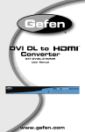
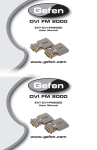
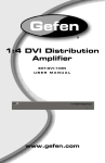
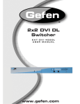
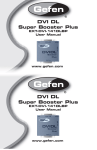
®
1x8 VGA CAT-5
Distribution Amplifier
EXT-VGA-CAT5-148S
USER
MANUAL
www.gefen.com
ASKING FOR ASSISTANCE
Technical Support:
Telephone
(818) 772-9100
(800) 545-6900
Fax
(818) 772-9120
Technical Support Hours:
8:00 AM to 5:00 PM Monday through Friday PST (Pacific Standard Time)
Write To:
Gefen Inc.
C/O Customer Service
20600 Nordhoff St.
Chatsworth, CA 91311
[email protected]
www.gefen.com
Notice
Gefen Inc. reserves the right to make changes in the hardware, packaging and any
accompanying documentation without prior written notice.
1X8 VGA CAT5 Distribution Amplifier is a trademark of Gefen Inc.
© 2009 Gefen Inc., All Rights Reserved
All trademarks are the property of their respective companies.
Rev X1
TABLE OF CONTENTS
1.
Introduction / Operation Notes
2.
Features
3.
Sender Panel Descriptions
4.
Receiver Panel Descriptions
5.
Connecting and Operating the 1X8 VGA CAT5 Distribution Amplifier
6.
How to Adjust the Picture
7.
Network Cable Wiring Diagram
8.
Specifications
9.
Warranty
INTRODUCTION
One VGA Input, Eight VGA Outputs The 1:8 VGA CAT5 Distribution Amplifier is the
perfect solution for anyone who needs to send one source to multiple displays in remote locations at the same time. The 1:8 VGA CAT5 Distribution Amplifier has eight
RJ-45 output connector and one VGA input. The 1:8 VGA CAT5 Distribution Amplifier's RJ-45 connectors are connected to up to eight VGA CAT5 Distribution Amplifier
receivers using industry standard CAT5 cables. The receivers can be placed up to
330 feet away from the transmitter.
How it Works
Simply connect your VGA video source to the 1:8 VGA CAT5 Distribution Amplifier’s
input using the supplied VGA cable. Then connect up to eight VGA displays to the
VGA CAT5 receivers over 330 feet using CAT-5 Cable. Then power the 1:8 VGA
CAT5 Distribution Amplifier and the receivers will get power from the CAT5. Note:
VGA output 1 is the primary connection and is used for the main display.
OPERATION NOTES
READ THESE NOTES BEFORE INSTALLING
OR OPERATING THE 1X8 VGA CAT5 DA SYSTEM
•
Use industry standard Category-5 (CAT-5) cable to operate the 1x8 VGA CAT5
DA system. CAT-5e cable is preferred.
•
Please connect all the cables between the computer and the 1x8 VGA CAT5 DA
system before powering up the 1x8 VGA CAT5 DA Sender unit.
•
The 1x8 VGA CAT5 DA units are housed in a metal box for better RF shielding.
1
FEATURES
Features
•
Distributes easily up to eight VGA displays
•
Extends each display up to 330 feet
•
Maintains 1920 x 1200 and 1080p resolutions
•
Distributes and extends VGA or Component
•
Installs in seconds
Includes:
(1) 1x8 VGA CAT5 DA (Distribution Amplifier)
(1) 6’ VGA cables (M-F)
(1) 5V DC 6A Power Supply
(1) Users Manual
2
SENDER PANEL DESCRIPTIONS
Power LED
Connects to
5VDC power
supply
Video CAT5
Out 1-4
VGA Input
3
Video CAT5
Out 5-8
RECEIVER PANEL DESCRIPTIONS
Brightness Video
Trim Pot CAT5 In
Power
LED
VGA Out
4
CONNECTING AND OPERATING THE 1X8 VGA CAT5 Distrib. Amp.
How to Connect the 1x8 VGA CAT5 DA to your devices
1.
Connect the supplied VGA cable from the VGA video source into the 1x8 VGA
CAT5 DA Sender "VGA In".
2.
Connect a CAT-5e* cable from the "CAT5 Video Outs" on the 1x8 VGA CAT5
DA Sender to the "CAT5 Inputs" on the VGA CAT5 Distribution Receiver.
(Repeat for each Receiver unit)
3.
Connect the VGA cable from the display to the "VGA Out" on the VGA CAT5
4.
Distribution Receiver. (Repeat for each Receiver unit)
5.
Plug the 5VDC power supply into the 1x8 VGA CAT5 DA Sender.
5
HOW TO ADJUST THE PICTURE
The first step in adjusting the video quality is to display text and a graphic on your monitor
(i.e. desktop icons). Then set your computer to the resolution that you will be using most
frequently. The dip switches are used to set the focus and sharpness of the picture to
the best possible setting. Set the dip switches to the settings that are recommended
for the different lengths of CAT5 cable (see chart below). Verify that the picture quality
is to your satisfaction. If the recommended setting does not produce a great quality
picture, try using a different dip switch setting. The trim pod next to the VGA connector
on the 1x8 VGA CAT5 DA R allows brightness adjustments for video.
0-25 Feet
26-100 Feet
101-200 Feet
201-300 Feet
301 Feet and Up
All dip switches OFF for all colors.
Set dip switch #1 ON all colors. 2,3,4 remain OFF.
Set dip switch #2 ON all colors. 1,3,4 remain OFF.
Set dip switch #3 ON all colors. 1,2,4 remain OFF.
Set dip switch #4 ON all colors. 1,2,3 remain OFF.
NOTE: The dip switches are set to the OFF position when the switch is closest to the
number or in the down position.
6
NETWORK CABLE WIRING DIAGRAM
Gefen has specifically engineered their products to work with the TIA/EIA-568-B
specification. Please adhere to the table below when field terminating cable for
use with Gefen products. Failure to do so may produce unexpected results and
reduced performance.
Pin
Color
1
Orange / White
2
Orange
3
Green / White
4
Blue
5
Blue / White
6
Green
7
Brown / White
8
Brown
12345678
Category 5 cabling comes in stranded and solid core types. Gefen recommends
using solid core cabling.
7
SPECIFICATIONS
Video Amplifier Bandwidth: ............................................................................350 MHz
Input Video Signal: ...................................................................................1.2 volts p-p
Input Sync Signal: ..............................................................................5 volts p-p (TTL)
Horizontal Frequency Range: ...................................................................15 - 70 KHz
Vertical Frequency Range: ........................................................................30 - 170 Hz
Video In:............................................................................................................. HD-15
Video out: ...........................................................................................................HD-15
Link Connector: ..................................................................................................RJ-45
Power Supply: ..........................................................................5 VDC / 8A (External)
Power Consumption: ..........................................................................30 Watts (max.)
Sender Dimensions: ..............................................................8.5"W x 1.75" H x 4.5"D
Receiver Dimensions: ........................................................................1"W x 1"H x 4"D
Shipping Weight: ................................................................................................4 Lbs.
8
WARRANTY
Gefen warrants the equipment it manufactures to be free from defects in material
and workmanship.
If equipment fails because of such defects and Gefen is notified within two (2)
years from the date of shipment, Gefen will, at its option, repair or replace the
equipment, provided that the equipment has not been subjected to mechanical,
electrical, or other abuse or modifications. Equipment that fails under conditions
other than those covered will be repaired at the current price of parts and labor in
effect at the time of repair. Such repairs are warranted for ninety (90) days from
the day of reshipment to the Buyer.
This warranty is in lieu of all other warranties expressed or implied, including
without limitation, any implied warranty or merchantability or fitness for any
particular purpose, all of which are expressly disclaimed.
1.
Proof of sale may be required in order to claim warranty.
2.
Customers outside the US are responsible for shipping charges to and from
Gefen.
3.
Copper cables are limited to a 30 day warranty and cables must be in their
original condition.
The information in this manual has been carefully checked and is believed to
be accurate. However, Gefen assumes no responsibility for any inaccuracies
that may be contained in this manual. In no event will Gefen be liable for
direct, indirect, special, incidental, or consequential damages resulting from
any defect or omission in this manual, even if advised of the possibility of such
damages. The technical information contained herein regarding the features and
specifications is subject to change without notice.
For the latest warranty coverage information, please visit Gefen’s Warranty web
page at http://www.gefen.com/kvm/aboutus/warranty.jsp
PRODUCT REGISTRATION
Please register your product online by visiting Gefen’s web site at
http://www.gefen.com/kvm/Registry/Registration.jsp
9
Rev X1
20600 Nordhoff St., Chatsworth CA 91311
1-800-545-6900
818-772-9100
www.gefen.com
Pb
fax: 818-772-9120
[email protected]