1
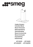
Libretto di Istruzioni
Manuel d’Instructions
Instructions Manual
Gebruiksaanwijzing
Bedienungsanleitung
Bruksanvisning
Manual de instrucciones
Manual de Instruções
Руководство по эксплуатации
KSE951X - KSE912X
RECOMMENDATIONS AND SUGGESTIONS
The Instructions for Use apply to several versions of this appliance. Accordingly, you may find descriptions of individual features that do not apply to
your specific appliance.
INSTALLATION
• The manufacturer will not be held liable for any damages resulting from incorrect or improper installation.
• The minimum safety distance between the cooker top and the extractor
hood is 650 mm.
• Check that the mains voltage corresponds to that indicated on the rating
plate fixed to the inside of the hood.
• For Class I appliances, check that the domestic power supply guarantees
adequate earthing.
Connect the extractor to the exhaust flue through a pipe of minimum diameter 120 mm. The route of the flue must be as short as possible.
• Do not connect the extractor hood to exhaust ducts carrying combustion
fumes (boilers, fireplaces, etc.).
• If the extractor is used in conjunction with non-electrical appliances (e.g. gas
burning appliances), a sufficient degree of aeration must be guaranteed in
the room in order to prevent the backflow of exhaust gas. The kitchen must
have an opening communicating directly with the open air in order to
guarantee the entry of clean air.
USE
• The extractor hood has been designed exclusively for domestic use to eliminate kitchen smells.
• Never use the hood for purposes other than for which it has been designed.
• Never leave high naked flames under the hood when it is in operation.
• Adjust the flame intensity to direct it onto the bottom of the pan only, making
sure that it does not engulf the sides.
• Deep fat fryers must be continuously monitored during use: overheated oil
can burst into flames.
• Do not flambè under the range hood; risk of fire
• This appliance is not intended for use by persons (including children) with
reduced physical, sensory or mental capabilities, or lack of experience and
knowledge, unless they have been given supervision or instruction concerning use of the appliance by a person responsible for their safety.
• Children should be supervised to ensure that they do not play with the appliance.
650 mm min.
MAINTENANCE
• Switch off or unplug the appliance from the mains supply before carrying out
any maintenance work.
• Clean and/or replace the Filters after the specified time period.
• Clean the hood using a damp cloth and a neutral liquid detergent.
The symbol
on the product or on its packaging indicates that this product may not be treated
as household waste. Instead it shall be handed over to the applicable collection point for the
recycling of electrical and electronic equipment. By ensuring this product is disposed of correctly,
you will help prevent potential negative consequences for the environment and human health,
which could otherwise be caused by inappropriate waste handling of this product. For more
detailed information about recycling of this product, please contact your local city office, your
household waste disposal service or the shop where you purchased the product.
EN
2
27
7
CHARACTERISTICS
433
90
max. 1055
132
650 min.
60
259
740
min. 740
Dimensions
300
260
490
108
150
Components
Ref.
1
2
2.1
2.2
9
10
14.1
15
Q.ty Product Components
1 Hood Body, complete with: Controls, Light, Blower,
Filters
1 Telescopic Chimney comprising:
1 Upper Section
1 Lower Section
1 Reducer Flange ø 150-120 mm
1 Damper
2 Air Outlet Connection Extension
1 Air Outlet Connection
15
14.1
12a 7.2.1
10
2.1
EN
12c
2
2.2
Ref. Q.ty Installation Components
7.2.1 2 Upper Chimney Section Fixing Brackets
11
6 Wall Plugs
12a
6 Screws 4,2 x 44,4
12c
6 Screws 2,9 x 9,5
Q.ty Documentation
1 Instruction Manual
11
9
11
12a
1
2
28
8
INSTALLATION
1÷2
Wall drilling and bracket fixing
116 116
650 min.
320
11
12a
X
7.2.1
Wall marking:
• Draw a vertical line on the supporting wall up to the ceiling, or as high as practical, at the
centre of the area in which the hood will be installed.
• Draw a horizontal line at 650 mm above the hob. Place bracket 7.2.1 on the wall as shown
about 1-2 mm from the ceiling or upper limit aligning the centre (notch) with the vertical
reference line.
• Mark the wall at the centres of the holes in the bracket.
• Place bracket 7.2.1 on the wall as shown at X mm below the first bracket (X = height of the
upper
chimney section supplied), aligning the centre (notch) with the vertical line.
• Mark the wall at the centres of the holes in the bracket.
• Mark a reference point as indicated at 116 mm from the vertical reference line and 320 mm
above the horizontal reference line.
• Repeat this operation on the other side.
• Drill ø 8 mm holes at all the centre points marked.
• Insert the wall plugs 11 in the holes.
• Fix the brackets using the 12a (4,2 x 44,4) screws supplied.
• Insert the two screws 12a (4,2 x 44,4) supplied in the hood body fixing holes, leaving a gap
of 5-6 mm between the wall and the head of the screw.
EN
2
29
9
Mounting the hood body
• Before attaching the hood body, tighten the two screws Vr located on the hood body mounting points.
• Hook the hood body onto the screws 12a.
• Fully tighten support screws 12a.
• Adjust screws Vr to level the hood body.
Vr
12a
Connections
DUCTED VERSION AIR EXHAUST SYSTEM
When installing the ducted version, connect the hood to the
chimney using either a flexible or rigid pipe ø 150 or 120mm, the
choice of which is left to the installer.
To install a ø 150
• To install the dumper 10
• Fix the pipe in position using sufficient pipe clamps (not supplied).
To install a ø 120
• To install a ø 120 mm air exhaust connection, insert the reducer flange 9 on the dumper 10.
• Fix the pipe in position using sufficient pipe clamps (not supplied).
• Remove any activated charcoal filters.
RECIRCULATION VERSION AIR OUTLET
• Push fit connection 15 onto the hood body outlet.
• Insert the connection extension pieces laterally 14.1 in connection 15.
• Make sure that the outlet of the extension pieces 14.1 is horizontally and vertically aligned with the chimney outlets. If this
is not the case, adjust the position by either reversing the connection extension pieces 14.1 and then reassemble as described
previously.
• Ensure that the activated charcoal filters have been inserted.
EN
ø 150
10
ø 120
9
10
15
14.1
3
30
0
ELECTRICAL CONNECTION
• Connect the hood to the mains through a two-pole switch having a contact gap of at least 3 mm.
• Remove the grease filters (see paragraph Maintenance) being
sure that the connector of the feeding cable is correctly inserted
in the socket placed on the side of the fan.
7.2.1
Chimney assembly
Upper exhaust Chimney
• Slightly widen the two sides of the upper chimney and hook
them behind the brackets 7.2.1, making sure that they are well
seated.
• Secure the sides to the brackets using the 4 screws 12c (2,9 x
9,5) supplied.
Lower exhaust Chimney
• Slightly widen the two sides of the chimney and hook them
between the upper chimney and the wall, making sure that they
are well seated.
• Fix the lower part laterally to the hood body using the 2 screws
12c (2,9 x 9,5) supplied.
EN
12c
2.1
2
2.2
12c
3
31
1
USE
Control board
Key
A
B
C
D
E
F
G
H
I
L
Function
Switches the motor on and off at the latest
selected speed
Decreases the suction speed.
Increases the suction speed.
By pressing this key it is possible to start the
intensive speed from any previously selected
speed. This speed has been timed at 10 minutes. After that time the system activates automatically the latest selected speed. This function is recommended for cooking condition
where vapours and odours need to be eliminated immediately and quickly.
By pressing this key it is possible to set up the
motor to a suction speed at 100 m3/h. During
the intensive speed or the Delay-function this
function cannot be activated.
By pressing this key it is possible to set the
delayed shutdown of the hood to 30 minutes.
This function is suitable for a complete elimination of residual cooking odours. Functioning
only when the motor is on(not during the 24Hfunction or intensive function)
By pressing this key for about 2 seconds it is
possible to reset the filter saturation alarm.
Display
Indicates the selected speed
HI and the remaining time appear alternately.
The spot down at the right side flashes once a
second.
By pressing the key the function is stopped.
24 appears and the spot down at the right side
flashes while the motor is on.
By pressing the key the function is stopped.
The suction speed and the remaining time before the hood shut down appear alternately The
spot down at the right side flashes.
By pressing the key the function is stopped
After 100 working hours a FF appears. Metal
grease filters have to be washed.
After 200 working hours EF appears. Charcoal
filters have to replaced.
By pressing this key the intensity of the lighting system can be decreased cyclically.
Switches on/off the lighting system at the
maximum intensity.
By pressing this key the intensity of the lighting system can be increate intensity.
Keyboard lock: it is possible to jam the keyboard when, for example, cleaning the glass. The motor and
lights are switched off.
By pressing the D-key (Intensive function) the keyboard block can be activated or deactivated. This function is confirmed by a Beep and by moving motor LEDS on display.
EN
3
32
2
MAINTENANCE
Metal grease filters
Filters can be washed in the dish machine. They need to be
washed when FF-sign appears on the display or in any case every
2 months, or even more frequently in case of particularly intensive use of the hood.
Alarm reset
• Press the G-key for at least 2 seconds.
Cleaning
• Remove the filters one at a time holding them up with one
hand and pulling the handle downwards with the other hand at
the same time.
• Wash the filters. Pay attention not to bend them. Make sure
that filters are completely dry before putting them into their
seat. (a possible modification of the filter surface doesn’t influence its efficiency).
• Place the filters again into their seats and make sure that the
handle of the filter remains outside.
EN
3
33
3
Charcoal filter (recycling version)
This filter cannot be washed or regenerated. It has to be replaced when the EF appears on the
display or at least once every 4 months.
Activation of the alarm signal
• In the recycling version hoods the filter saturation alarm has to be activated during the installation or later.
• Switch off the hood and the lights.
• Press the E-key for about 5 seconds until the LED on the display start to move.
• Press the B-key within 5 seconds until a confirmation of the activated state of filter saturation alarm on the display appears:
• 2 flashings on EF - charcoal filter saturation alarm ACTIVATED
• 1 flashing on EF - charcoal filter saturation alarm DEACTIVATED.
SUBSTITUTION OF THE CHARCOAL FILTER
Alarm reset
• Switch off the motor and the lighting system.
• Press the G-key for at least 2 seconds.
Substitution of the filter
• Remove the metal grease filters.
• Remove the charcoal filter as indicated in the picture.
• Place the filter again into its seat.
• Place again the metal grease filters into their place.
Lighting
LIGHT REPLACEMENT
20 W halogen light.
• Remove the 2 screws fixing the Lighting support, and pull it
out of from the Hood.
• Extract the lamp from the Support.
• Replace with another of the same type, making sure that the
two pins are properly inserted in the lamp holder socket holes.
• Replace the Support, fixing it in place with the two screws removed as above.
EN
3
34
4