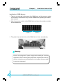
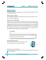
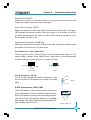
1
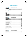
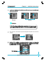
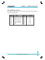
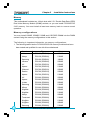
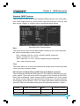
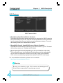
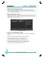
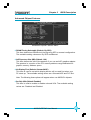
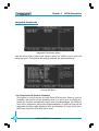
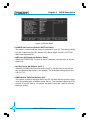
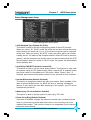
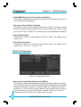
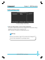
Statement: This manual is the intellectual property of Foxconn, Inc. Although the information in this manual may be changed or modified at any time, Foxconn does not obligate itself to inform the user of these changes. Trademark: All trademarks are the property of their respective owners. Version: User’s Manual V1.0 in English for 865G/GV/PE7MC motherboard. P/N: 91-181-U65-M7-0E Symbol description: Note: refers to important information that can help you to use motherboard better. Attention: indicates that it may damage hardware or cause data loss, and tells you how to avoid such problems. Warning: means that a potential risk of property damage or physical injury exists. More information: If you want more information about our products, please visit Foxconn’s website: www.foxconnchannel.com 865G&GV&PE7MC-English preface.p65 1 2004-9-11, 10:50 Item Checklist: Thank for your purchasing Foxconn’s 865G/GV/PE7MC motherboard. Please check the package; if there are missing or damaged items, contact your distributor as soon as possible. 865G/GV/PE7MC motherboard (x1) Foxconn Utility CD (x1) User Manual (x1) IDE Ribbon cable (x1) FDD Ribbon cable (x1) I/O Shield (x1) S-ATA Signal Cable (x2) S-ATA Power Cable (x1) 865G&GV&PE7MC-English preface.p65 2 2004-9-11, 10:50 Declaration of conformity HON HAI PRECISION INDUSTRY COMPANY LTD 66 , CHUNG SHAN RD., TU-CHENG INDUSTRIAL DISTRICT, TAIPEI HSIEN, TAIWAN, R.O.C. declares that the product Motherboard 865G/GV/PE7MC is in conformity with (reference to the specification under which conformity is declared in accordance with 89/336 EEC-EMC Directive) EN 55022/A1: 2000 Limits and methods of measurements of radio disturbance characteristics of information technology equipment EN 61000-3-2/A14:2000 Electromagnetic compatibility (EMC) Part 3: Limits Section 2: Limits for harmonic current emissions (equipment input current <= 16A per phase) EN 61000-3-3/A1:2001 Electromagnetic compatibility (EMC) Part 3: Limits Section 2: Limits of voltage fluctuations and flicker in low-voltage supply systems for equipment with rated current <= 16A EN 55024/A1:2001 Information technology equipment-Immunity characteristics limits and methods of measurement Signature : Printed Name : Place / Date : James Liang 865G&GV&PE7MC-English preface.p65 3 Position/ Title : TAIPEI/2004 Assistant President 2004-9-11, 10:50 Declaration of conformity Trade Name: Model Name: Responsible Party: Address: Foxconn 865G/GV/PE7MC PCE Industry Inc. 458 E. Lambert Rd. Fullerton, CA 92835 Telephone: 714-738-8868 Facsimile: 714-738-8838 Equipment Classification: Type of Product: Manufacturer: Address: FCC Class B Subassembly Motherboard HON HAI PRECISION INDUSTRY COMPANY LTD 66 , CHUNG SHAN RD., TU-CHENG INDUSTRIAL DISTRICT, TAIPEI HSIEN, TAIWAN, R.O.C. Supplementary Information: This device complies with Part 15 of the FCC Rules. Operation is subject to the following two conditions : (1) this device may not cause harmful interference, and (2) this device must accept any interference received, including interference that may cause undesired operation. Tested to comply with FCC standards. Signature : 865G&GV&PE7MC-English preface.p65 Date : 4 2004 2004-9-11, 10:50 Table of Contents Chapter Product Introduction 865G/GV/PE7MC Chapter Installation Instructions Supply ............................................................................................ Chapter BIOS Description Standard CMOS Features .......................................................................... 27 BIOS Features ........................................................................................... Advanced BIOS Features .......................................................................... Advanced Chipset Features ...................................................................... Integrated Peripherals ................................................................................ Power Management Setup ......................................................................... PnP/PCI Configurations ............................................................................... PC Health Status ........................................................................................ Frequency/Voltage Control ......................................................................... Load Fail-Safe Defaults ............................................................................. Load Optimized Defaults ............................................................................ Set Supervisor/User Password ................................................................. 42 Save & Exit Setup ...................................................................................... Exit Without Saving .................................................................................... Chapter Driver CD Introduction Utility CD content ........................................................................................ 45 Start to install drivers ................................................................................. 46 865G&GV&PE7MC-English preface.p65 5 2004-9-11, 10:50 Warning: 1. Attach the CPU and heatsink using silica gel to ensure full contact. 2. It is suggested to select high-quality, certified fans in order to avoid damage to the motherboard and CPU due high temperatures. 3. Never turn on the machine if the CPU fan is not properly installed. 4. Ensure that the DC power supply is turned off before inserting or removing expansion cards or other peripherals, especially when you insert or remove a memory module. Failure to switch off the DC power supply may result in serious damage to your system or memory module. Warning: We cannot guarantee that your system will operate normally while over-clocked. Normal operation depends on the over-clock capacity of your device. Attention: Since BIOS programs are upgraded from time to time, the BIOS description in this manual is just for reference. We do not guarantee that the content of this manual will remain consistent with the actual BIOS version at any given time in the future. Attention: The pictures of objects used in this manual are just for your reference. Please refer to the physical motherboard. 865G&GV&PE7MC-English preface.p65 6 2004-9-11, 10:50 1 Chapter Thank you for buying Foxconn’s 865G/GV/PE7MC motherboard. This series of motherboard is one of our new products, and offers superior performance, reliability and quality, at a reasonable price. This motherboard adopts the advanced Intel® 865G/ GV/PE+ ICH5 chipset, providing users a computer platform with a high integration-compatibility-performance price ratio. This chapter includes the following information: Main Features Motherboard Layout Chapter 1 Product Introduction Main Features Size mATX form factor of 9.6 inch x 9.1 inch Microprocessor Supports Intel® Prescott-T processor in an LGA775 package Supports FSB at 533MHz/800MHz Supports Hyper-Threading technology Chipset Intel® Springdale chipset: Intel® 865G/GV/PE (North Bridge) + ICH5 (South Bridge) System Memory Two 184-pin DIMM slots Supports PC 3200/2700/2100 memory Supports 64/128/256/512 Mb technology up to 2GB Supports Dual-channel DDR USB 2.0 Ports Supports hot plug Eight USB 2.0 ports (four rear panel ports, two onboard USB headers providing four extra ports) Supports wake-up from S1 and S3 mode Supports USB 2.0 Protocol up to 480 Mbps transmission rate Onboard Serial ATA 150MBps transfer rate Supports two S-ATA devices Onboard 1394 (optional) Support hot plug With rate of transmission at 400Mbps Self-configured addressing Can connect with 2 independent 1394 units synchronously at most 2 865G/GV/PE7MC User Manual Chapter 1 Product Introduction Onboard LAN (optional) Supports 10/100/1000 (-K optional) Mbit/sec Ethernet LAN interface built-in on board Onboard Audio AC’97 2.3 Specification Compliant Supports SPDIF output Onboard Line-in jack, Microphone-in jack, Line-out jack Supports 5.1 channels audio (setting via software) Onboard Graphics (supported on 865G/GV7MC) Supports integrated VGA display functions (Intel Extreme Graphics) AGP 8X support (supported on 865G/PE7MC) AGP 8X (AGP 3.0) is the VGA interface specification that enabled enhanced graphics performance with high bandwidth speeds up to 2.12 GB/s. BIOS Licensed advanced AWARD (Phoenix) BIOS, supports flash ROM, plug-andplay Supports IDE, CD-ROM, SCSI HDD and USB device boot up Green Function Supports ACPI (Advanced Configuration and Power Interface) Supports S0 (normal), S1 (power on suspend), S3 (suspend to RAM), S4 (Suspend to disk - depends on OS), and S5 (soft - off). Expansion Slots Three PCI slots One AGP slot (supported on 865G/PE7MC only) Advanced Features PCI 2.3 specification compliant Supports Windows 98/2000/ME/XP soft-off Supports PC Health function (capable of monitoring system voltage, CPU, system temperature, and fan speed) 865G/GV/PE7MC User Manual 3 Chapter 1 Product Introduction 865G/GV/PE7MC Layout 1 2 23 3 4 22 5 21 20 6 7 8 19 9 18 10 17 11 12 16 13 14 15 1.CD_IN connector 2.Front Audio connector 13.Serial ATA connectors 14.IDE connectors 3.1394 header 4.SPDIF_OUT connector 15.FDD connector 16.IrDA header 5.PCI slots 6.USB headers 17.20-pin ATX power connector 18.184-pin DIMM slots 7.South Bridge: ICH5 chipset 8.FAN1 connector 19.CPU FAN connector 20.North Bridge: 865G/GV/PE chipset 9.Clear CMOS jumper 10.BIOS protection jumper 21.CPU socket 22.AGP slot (only for 865G/PE7MC) 11.Front panel connector 12.Chassis intruder connector 23.4-pin ATX_12V power connnector Note: The above motherboard layout is provided for reference only; please refer to the physical motherboard. 4 865G/GV/PE7MC User Manual Chapter 1 Product Introduction 2 Chapter This chapter introduces the hardware installation process, including the installation of the CPU, memory, power supply, slots, rear panel and pin headers, and the mounting of jumpers. Caution should be exercised during the installation of these modules. Please refer to the motherboard layout prior to any installation and read the contents in this chapter carefully. This chapter includes the following information: CPU Memory Power supply Rear Panel Connectors Other Connectors Expansion Slots Jumpers 865G/GV/PE7MC User Manual 5 Chapter 2 Installation Instructions CPU This motherboard supports single Pentium® 4 Processor including Prescott desktop CPUs in an LGA 775 package. It also supports Hyper-Threading Technology. Installation of CPU Load lever Load plate Load cap gLoaLoad stiffener Lifted tab 6 865G/GV/PE7MC User Manual Chapter 2 Correct Installation Instructions Wrong Lift up the lever. Use thumb to open the load plate. Be careful not to touch the contacts. 865G/GV/PE7MC User Manual 7 Chapter 2 Installation Instructions Note : Excessive temperatures will severely damage the CPU and system. Therefore, you should install CPU cooling fan and make sure that the cooling fan works normally at all times in order to prevent overheating and damaging to the CPU. Please refer to your CPU fan user guide to install it properly. 8 865G/GV/PE7MC User Manual Chapter 2 Installation Instructions CPU Qualified Vendor List The following table lists the CPUs that have been tested and qualified for use with this motherboard. Vendor Type FSB Frequency Intel Pentium (Prescott) 533 2.8G Intel Pentium (Prescott) 800 2.8G Intel Pentium (Prescott) 800 3.0G Intel Pentium (Prescott) 800 3.2 G Intel Pentium (Prescott) 800 3.6 G Intel P4EE 800 3.4 G 865G/GV/PE7MC User Manual 9 Chapter 2 Installation Instructions Memory This motherboard includes two 184-pin slots with 2.5 V Double Data Rate (DDR) Dual Inline Memory Module (DIMM) sockets, so you can install PC3200/2700/ 2100 memory. You must install at least one memory bank to ensure normal operation. Memory configurations You may install 128MB, 256MB, 512MB and 1GB DDR DIMMs into the DIMM sockets using the memory configurations in this section. The following is important information on memory configurations: 1. The following table lists the PC3200/2700/2100 memory modules that have been tested and qualified for use with this motherboard. Vender 10 Type Size HY PC2100 (DDR266) 256MB Nanya PC2100 (DDR266) 512MB Samsung PC2100 (DDR266) 128MB Infineon PC2100 (DDR266) 256MB HY PC2700 (DDR333) 256MB Apacer PC2700 (DDR333) 512MB Winbond PC2700 (DDR333) 256MB Rambo PC2700 (DDR333) 256MB Apacer PC2700 (DDR333) 512MB HY PC3200 (DDR400) 256MB Apacer PC3200 (DDR400) 256MB V-data PC3200 (DDR400) 256MB Samsung PC3200 (DDR400) 512MB Micron PC3200 (DDR400) 256MB KingMax PC3200 (DDR400) 256MB KingMax PC3200 (DDR400) 512MB Nanya PC3200 (DDR400) 256MB Transcend PC3200 (DDR400) 512MB KingSton PC3200 (DDR400) 512MB KingSton PC3200 (DDR400) 256MB Samsung PC3200 (DDR400) 512MB 865G/GV/PE7MC User Manual Chapter 2 Installation Instructions 2. In dual-channel configurations, install only identical (the same type and size) DDR DIMMs for each channel. 3. Make sure that the memory frequency matches the CPU FSB (Front Side Bus). Refer to the following table. CPU FSB 800 MHz DDR DIMM Type Memory Frequency PC3200/PC2700/PC2100 400/333/266 MHz 533 MHz PC2700/PC2100 333/266 MHz Note: 1. When using FSB 800MHz CPU, PC2700DDR DIMMs may run only at 320MHz(not 333MHz) due to chipset limitation. 2. The following FSB/DDR ratios are not supported: 400/333, 400/400. 4. Double-sided DDR DIMMs with X16 (databus width=16-bit) memory chips are not supported due to chipset limitations. 865G/GV/PE7MC User Manual 11 Chapter 2 Installation Instructions Installation of DDR Memory 1. There is only one gap in the center of the DIMM slot, and the memory module can be fixed in one direction only. Unlock a DIMM slot by pressing the module clips outward. 2. Align the memory module to the DIMM slot, and insert the module vertically into the DIMM slot. 104 Pins 80 Pins 3. The plastic clips at both sides of the DIMM slot will lock automatically. Warning : Be sure to unplug the AC power supply before adding or removing expansion cards or other system peripherals, especially the memory devices, otherwise your motherboard or the system memory might be seriously damaged. 12 865G/GV/PE7MC User Manual Chapter 2 Installation Instructions Power Supply This motherboard uses an ATX power supply. In order to avoid damaging any devices, make sure that they have been installed properly prior to connecting the power supply. 4-pin ATX_12V Power Connector: PWR2 4-pin ATX_12V power connector The ATX power supply connects to PWR2 and provides power to the CPU. 1 2 GND GND 12V 12V 3 20-pin ATX power Connector: PWR1 PWR1 is the ATX power supply connector. Make 20-pin ATX power connector sure that the power supply cable and pins are properly aligned with the connector on the motherboard. Firmly plug the power supply cable into the connector and make sure it is secure. 4 5V 5V -5V GND GND GND 3.3V GND PS-ON -12V 20 11 10 1 12V Pw-OK 5V 5V 3.3V 5VSB GND GND GND 3.3V Attention: You have to press the power button for more than four seconds if you change the default “Instant-Off” setting to “Delay 4 Sec.” from the “Soft-Off by PWR-BTTN” option in the BIOS Power Management Setup. 865G/GV/PE7MC User Manual 13 Chapter 2 Installation Instructions Rear Panel Connectors This motherboard provides the ports as below: 4 Parallel Port (Printer Port) 6 1394 Port (optional) 8 LAN Port Line-in jack 1 PS/2 Mouse Connector Line-out jack 9 Microphone jack 2 PS/2 Keyboard Connector 3 Serial Port (COM1) 5 VGA Port (only for 865G/ GV7MC) 7 USB 2.0 Ports PS/2 Mouse Connector This green 6-pin connector is for a PS/2 mouse. 1 PS/2 Keyboard Connector This purple 6-pin connector is for a PS/2 keyboard. 2 Serial Port (COM1) This 9-pin COM1 port is for pointing devices or other serial devices. 3 Parallel Port (Printer Port) This 25-pin port connects a parallel printer, a scanner, or other devices. 4 VGA Port (Only for 865G/GV7MC) The VGA Port is for output to a VGA-compatible device. 5 1394 Port (Optional) This digital interface supports electronic devices such as digital cameras, scanners, and printers. 6 USB 2.0 Ports These four Universal Serial Bus (USB) ports are available for connecting USB 2.0/1.1 devices. 7 14 865G/GV/PE7MC User Manual Chapter 2 8 Installation Instructions LAN Port (optional) This port allows connection to a Local Area Network (LAN) through a network hub. Line-in jack, Line-out jack, Microphone jack When using a two-channel sound source, the Line-out jack is used to connect to 9 speaker or headphone; the Line-in port connects to an external CD player, tape player or other audio device. The Microphone jack is used to connect to the microphone. Line-in Line-out Microphone When using a 6-channel sound source, connect the front speaker to the green audio output; connect the surround sound speaker to the blue audio input; connect the center speaker/subwoofer to the red Microphone input, as shown in the following figure: Blue Green Center Red Front Left Front Right Rear Left Rear Right Subwoofer 865G/GV/PE7MC User Manual 15 Chapter 2 Installation Instructions Other Connectors This motherboard includes connectors for FDD, IDE HDD, Serial ATA, USB, IR module, and others. FDD Connector: FLOPPY This motherboard includes a standard FDD connector, supporting 360K, 720K, 1. 2M, 1.44M, and 2.88M FDDs. HDD Connectors: PIDE & SIDE These connectors support the provided Ultra DMA 100/66/33 IDE hard disk ribbon cable. Connect the cable’s blue connector to the primary (recommended) or secondary IDE connector, then connect the gray connector to the Ultra DMA 100/66/33 slave device (hard disk drive) and the black connector to the Ultra DMA 100/66/33 master device. If you install two hard disks, you must configure the second drive as a slave device by setting its jumper accordingly. Refer to the hard disk documentation for the jumper settings. Attention: Ribbon cables are directional, therefore, make sure to always connect with the cable on the same side as pin 1 of the PIDE/SIDE or FDD connector on the motherboard. Front Panel Connector: FP1 This motherboard includes one connector for connecting the front panel switch and LED indicators. 1 IDE_LED + + - - GND RESET PLED PWRBTN# NC FP1 IDE LED Connector (IDE_LED) The connector connects to the case’s IDE indicator LED indicating the activity status of hard disks. 16 865G/GV/PE7MC User Manual Chapter 2 Installation Instructions Reset Switch (RESET) Attach the connector to the Reset switch on the front panel of the case; the system will restart when the switch is pressed. Power LED Connector (PLED) Attach the connector to the power LED on the front panel of the case. The Power LED indicates the system’s status. When the system is in S0 status, the LED is on. When the system is in S1 status, the LED is blink; When the system is in S3, S4, S5 status, the LED is off. Power Button Connector (PWRBTN#) Attach the connector to the power switch of the case. Pushing this switch allows the system to be turned on and shut down. Fan Connectors : CPU_FAN, FAN1 The fan speed of CPU_FAN and FAN1 can be detected and viewed in “PC Health Status” section of the CMOS Setup. These fans will be automatically turned off after the system enters S3, S4 and S5 mode. 1 1 GROUND POWER CONTROL SENSE +12V GND SENSE CPU FAN FAN1 CD_IN Connector: CD_IN CD_IN is Sony standard CD audio connectors, it can CD_R be connected to a CD-ROM drive through a CD audio cable. GND CD_IN CD_L S-ATA Connectors: CN20, CN21 The S-ATA header is used to connect the S-ATA device to the motherboard. These connectors support the thin Serial ATA cables for primary internal storage devices. The current Serial ATA interface allows up to 150MB/s data transfer rate, faster than the standard parallel ATA with 133MB/s (Ultra ATA/133). 865G/GV/PE7MC User Manual GND RX+ GND GND TX+ RX- TX- SATA _1/SATA _2 17 Chapter 2 Installation Instructions Front Audio Connector : F_AUDIO The audio interface provides two kinds of audio output choices: the Front Audio, the Rear Audio. Their priority is sequenced from high to low (Front Audio to Rear Audio). If headphones are plugged into the front panel of the chassis (using the Front Audio), then the Line-out (Rear 1 2 MIC_GND MIC_IN MIC_PWR +5VA AUD_RET-R AUD_OUT-R Empty NA AUD_OUT-L AUD_RET-L 9 Audio) on the rear panel will not work. If you do not want to use the Front Audio, pin 5 and 6, pin 10 F_AUDIO 9 and 10 must be SHORT, and then the signal will be sent to the rear audio port. SP The SPDIF out connector is capable of providing digital GND SPDIF_OUT audio to external speakers or compressed AC3 data to an external Dolby digital decoder. Empty 5V_SYS SPDIF_OUT The connectors connect to the chassis security switch on the case. The system can detect the chasis intrusion through the status of this connector. If the connector has been closed once, the system will send a message. To utilize this function, set “Intruder# Detection” to “Enabled” in the “Power Management Setup” section of the CMOS Setup. Save and exit, then boot the operating system once to make sure this function takes effect. 2 GND 1 INTRUDERJ INTR USB Headers: F_USB1, F_USB2 Besides four USB ports on the rear panel, the series of motherboards also have two 10-pin headers on board which may connect to front panel USB cable(optional) to provide additional four USB ports. 10 2 Empty VCC VCC GND GND D2- D3- D1+ D0+ D2+ D3+ D1- D0- GND GND VCC VCC Empty 2 18 1 9 NC 1 NC 9 F_USB 1 10 F_USB 2 865G/GV/PE7MC User Manual Chapter 2 Installation Instructions Note: 1. You must install the driver before you use the USB 2.0 function. 2. NEVER connect a 1394 cable to the F_USB1 or F_USB2 connectors. Doing so will damage the motherboard! 1394 Header: F_1394 (Optional) The 1394 expansion cable can be connected to either the front (provided that the front panel of your chassis is equipped with the appropriate interface) or rear panel of the chassis. 10 9 GND +12V Empty TPB- TPB + TPA - TPA + +12V GND 2 1 F_1394 IrDA Header: IR This connector supports wireless transmitting and receiving device. Before using this function, configure the settings of IR Mode from the “Integrated Peripherals” section of the CMOS Setup. TX GND RX Empty +5V 1 IR 865G/GV/PE7MC User Manual 19 Chapter 2 Installation Instructions Expansion Slots This motherboard includes three 32-bit Master PCI bus slots and one AGP slot (only for 865G/PE7MC). PCI Slots The expansion cards can be installed in the three PCI slots. When you install or take out such cards, you must make sure that the power plug has been pulled out. Please read carefully the instructions provided for such cards, and install and set the necessary hardware and software for such cards, such as the jumper or BIOS setup. AGP Slot (only for 865G/PE7MC) This motherboard has Accelerated Graphics Port (AGP) slot that only supports 1. 5V AGP card. When you use an AGP card, make sure that your AGP card with 1. 5V specification. Note the notches on the card golden fingers to ensure that they fit the AGP slot on your motherboard. Installing an expansion card 1. Before installing the expansion card, read the documentation that came with it and make the necessary hardware settings for the card. 2. Make sure to unplug the power cord before adding or removing expansion cards. 3. Remove the bracket opposite to the slot that you intend to use. 4. Align the card connector with the slot and press firmly until the card is completely seated on the slot. 5. Secure the card to the chassis with the screw you removed earlier. Warning: The motherboard may be damaged if a 3.3V AGP card is used. Make sure that your AGP card is 1.5 V specification. Note the notches on the card golden fingers to ensure that they fit the AGP slot on your motherboard. 20 865G/GV/PE7MC User Manual Chapter 2 Installation Instructions AGP Qualified Vendor List The following table lists the AGP cards that have been tested and qualified for use with this motherboard. Vender Type Video Memory ASUS ASUS V9560 8X 128MB ASUS ASUS V7700 4X 32MB ASUS ASUS V9280 128MB ATI ATI Radeon7000 64MB CP ATI 9700 8X AGP 128MB Elsa Elsa Geforce4 MX440 64MB MSI MSI 8923 128MB LeadTek LeadTek A340 128MB MSI MSI 8891 128MB MSI MSI TI4200 128MB Unika UNIKA 7917 Geforce4 MX440 64MB Note: Make sure to use only the tested and qualified AGP cards listed above. Other AGP cards manufactured by other vendors may not be suitable for this motherboard. 865G/GV/PE7MC User Manual 21 Chapter 2 Installation Instructions Jumpers The users can change the jumper settings on this motherboard if needed. This section explains how to use the various functions of this motherboard by changing the jumper settings. Users should read the following content carefully prior to modifying any jumper settings. Description of Jumpers 1. 2. For the jumpers on this motherboard, pin 1 can be identified by the silkscreen printed “ ” next to it. However, in this manual, pin 1 is simply labeled as “1”. The following table provides some explanation of the jumper pin settings. User should refer to this when adjusting jumper settings. Jumper 1 1 Diagram Definition Description 1-2 Set pin1 and pin2 closed 2-3 Set pin2 and pin3 closed 1 Closed Set the pin closed 1 Open Set the pin opened 1 Clear CMOS Jumper: CLS CMOS This motherboard uses the CMOS RAM to store all the set parameters. The CMOS can be cleared by remov- Normal 3 2 (Default) 1 Clear 2 ing the CMOS jumper. How to clear CMOS? 3 1.Turn off the AC power supply and connect pins 1 and 2 together using the jumper cap. 2.Return the jumper setting to normal (pins 2 and 3 to gether with the jumper cap). 1 CLS CMOS 3.Turn the AC power supply on. Warning: 1. Disconnect the power cable before adjusting the jumper settings. 2. Do not clear the CMOS while the system is turned on. 22 865G/GV/PE7MC User Manual Chapter 2 Installation Instructions BIOS-Protection Jumper: TBL_EN If the jumper TBL_EN is set as Lock (Pin1 & Pin2), the system BIOS is protected from being attacked by a serious virus, such as the CIH virus. You will be unable to flash the BIOS to the motherboard when the system BIOS is protected. Flash write Enabled (Default) Flash write Disabled TBL_EN 865G/GV/PE7MC User Manual 23 Appendix 3 Chapter This chapter tells how to change system settings through the BIOS Setup menus. Detailed descriptions of the BIOS parameters are also provided. You have to run the Setup Program when the following cases occur: 1. An error message appears on the screen during the system POST process. 2. You want to change the default CMOS settings. This chapter includes the following information: Enter BIOS Setup Main Menu Standard CMOS Features BIOS Features Advanced BIOS Features Advanced Chipset Features Integrated Peripherals Power Management Setup PnP/PCI Configurations PC Health Status Frequency/Voltage Control Load Fail-Safe Defaults Load Optimized Defaults Set Supervisor/User Password Save & Exit Setup Exit Without Saving 24 865M06 Series User Manual Chapter 3 BIOS Description Enter BIOS Setup The BIOS is the communication bridge between hardware and software, correctly setting up the BIOS parameters is critical to maintain optimal system performance. Power on the computer, when the following message briefly appears at the bottom of the screen during the POST (Power On Self Test), press <Del> key to enter the AWARD BIOS CMOS Setup Utility. Press TAB to show POST screen, DEL to enter SETUP Note: We do not suggest that you change the default parameters in the BIOS Setup, and we shall not be responsible for any damage that result from any changes that you make. Main Menu The main menu allows you to select from the list of setup functions and two exit choices. Use the arrow keys to select among the items and press <Enter> to accept or go to the sub-menu. Main Menu The items in the main menu are explained below: Standard CMOS Features The basic system configuration can be set up through this menu. BIOS Features The special features can be set up through this menu. 865G/GV/PE7MC User Manual 25 Chapter 3 BIOS Description Advanced BIOS Features The advanced system features can be set up through this menu. Advanced Chipset Features The values for the chipset can be changed through this menu, and the system performance can be optimized. Integrated Peripherals Onboard peripherals can be set up through this menu. Power Management Setup All the items of Green function features can be set up through this menu. PnP/PCI Configurations The system’s PnP/PCI settings and parameters can be modified through this menu. PC Health Status This will display the current status of your PC. Frequency/Voltage Control Frequency and voltage settings can be adjusted through this menu. Load Fail-Safe Defaults The fail-safe default BIOS settings can be loaded through this menu. Load Optimized Defaults The optimal performance settings can be loaded through this menu, however, the stable default values may be affected. Set Supervisor/User Password The supervisor/user password can be set up through this menu. Save & Exit Setup Save CMOS value settings to CMOS and exit setup. Exit Without Saving Abandon all CMOS value changes and exit setup. 26 865G/GV/PE7MC User Manual Chapter 3 BIOS Description Standard CMOS Features This sub-menu is used to set up the standard CMOS features, such as the date, time, HDD model and so on. Use the arrow keys select the item to set up, and then use the <PgUp> or <PgDn> keys to choose the setting values. Standard CMOS Features Menu Date This option allows you to set the desired date (usually as the current date) with the <day><month><date><year> format. Day—weekday from Sun. to Sat., defined by BIOS (read-only). Month—month from Jan. to Dec.. Date—date from 1st to 31st, can be changed using the keyboard. Year—year, set up by users. Time This option allows you to set up the desired time (usually as the current time) with <hour><minute><second> format. IDE Channel 0/1 Master/Slave & IDE Channel 2/3 Master (optional) These categories identify the HDD types of 2 IDE channels installed in the computer system. There are three choices provided for the Enhanced IDE BIOS: None, Auto, and Manual. “None” means no HDD is installed or set; “Auto” means the system can auto-detect the hard disk when booting up; by choosing “Manual” and changing Access Mode to “CHS”, the related information should be entered manually. Enter the information directly from the keyboard and press < Enter>: Cylinder number of cylinders Head number of heads Precomp write pre-compensation Landing Zone landing zone Sector number of sectors 865G/GV/PE7MC User Manual 27 Chapter 3 BIOS Description Award (Phoenix) BIOS can support 3 HDD modes: CHS, LBA and Large or Auto mode. CHS For HDD<528MB LBA For HDD>528MB & supporting LBA (Logical Block Addressing) Large For HDD>528MB but not supporting LBA Auto Recommended mode Drive A/B This option allows you to select the kind of FDD to be installed, including “None”, [360K, 5.25 in], [1.2M, 5.25 in], [720K, 3.5 in], [1.44M, 3.5 in] and [2.88 M, 3.5 in]. Video The following table is provided for your reference in setting the display mode for your system. EGA/VGA Enhanced Graphics Adapter / Video Graphic Array. For EGA, VGA, SEGA, SVGA, or PGA monitor adapters. CGA 40 Color Graphic Adapter, powering up in 40 column mode. CGA 80 Color Graphic Adapter, powering up in 80 column mode. MONO Monochrome adapter, including high resolution monochrome adapters. Halt On This category determines whether or not the computer will stop if an error is detected during powering up. All Errors Whenever the BIOS detects a nonfatal error, the system will stop and you will be prompted. No Errors The system boot will not stop for any errors that may be detected. All, But Keyboard The system boot will not stop for a keyboard error; but it will stop for all other errors. All, But Diskette The system boot will not stop for a diskette error; but it will stop for all other errors. All, But Disk/Key The system boot will not stop for a keyboard or disk error, but it will stop for all other errors. 28 865G/GV/PE7MC User Manual Chapter 3 BIOS Description Memory This is a Display-Only Category, determined by POST (Power On Self Test) of the BIOS. Base Memory The BIOS POST will determine the amount of base (or conventional) memory installed in the system. Extended Memory The BIOS determines how much extended memory is present during the POST. Total Memory Total memory of the system. 865G/GV/PE7MC User Manual 29 Chapter 3 BIOS Description BIOS Features BIOS Features Menu [SuperBoot] SuperBoot (Default: Disabled) SuperBoot allows system-relevant information to be stored in CMOS upon the first normal startup of your PC, and the relevant parameters will be restored to help the system start up more quickly on each subsequent startup. The available setting values are: Disabled and Enabled. [SuperBIOS-Protect] SuperBIOS-Protect (Default: Disabled) SuperBIOS-Protect function protects your PC from viruses, e.g. CIH. The available setting values are: Disabled and Enabled. [Super Speed] CPU Clock (Depending on the specification of the CPU) The conventional over-clock method uses the jumpers on the motherboard, and it is both troublesome and apt to errors. By using Super Speed, a CPU can be overclocked by keying in the desired in the CPU clock range. For more detailed information, please visit our website: http://www.foxconnchannel.com.cn Warning: Be sure your selection is right. CPU overclock will be dangerous! We will not be responsible for any damage caused. 30 865G/GV/PE7MC User Manual Chapter 3 BIOS Description Advanced BIOS Features Advanced BIOS Features Menu CPU Feature Press <Enter> to set the items of CPU feature. Please refer to page 32. Hard Disk Boot Priority This option is used to select the priority for HDD startup. After pressing <Enter>, you can select the HDD using the <PageUp>/<PageDn> or Up/Down arrow keys, and change the HDD priority using <+> or <->; you can exit this menu by pressing <Esc>. Virus Warning (Default: Disabled) Allows you to choose the VIRUS warning feature for IDE hard disk boot sector protection. If this function is enabled and someone attempts to write data into this area, BIOS will show a warning message on screen and an alarm will beep. The setting values are: Disabled and Enabled. Note: Such function provides protection to the start-up sector only; it does not protect the entire hard disk. Hyper-Threading Technology (Default: Enabled) This option is used to turn on or off the Hyper-Threading function of the CPU. The available setting values are: Disabled and Enabled. Note: This function will not be displayed until a CPU that supports HyperThreading has been installed. First/Second/Third Boot Device (Default: Floppy/Hard Disk/CDROM) This option allows you to set the boot device sequence. The available setting values are: Floppy, LS120, Hard Disk, CDROM, ZIP100, USB-FDD, USB-ZIP, USB-CDROM, LAN and Disabled. 31 865G/GV/PE7MC User Manual Chapter 3 BIOS Description Boot Other Device (Default: Enabled) With this function set to Enabled, the system will boot from some other devices if the first/second/third boot devices failed. The available setting values are: Disabled and Enabled. Security Option (Default: Setup) When it is set to “Setup”, a password is required to enter the CMOS Setup screen; When it is set to “System”, a password is required not only to enter CMOS Setup, but to startup your PC. CPU Feature Menu Delay Prior to Thermal (Default: 16 Min) This option is used to set up the time for CPU to enter the energy-saving mode. Note: The following options are used to set Prescott CPU. Thermal Management (Default: Thermal Monitor 1) This option is used to manage Prescott CPU thermal. Limit CPUID MaxVal (Default: depend on CPU) (optional) This option is used to set limit CPUID maxval. 32 865G/GV/PE7MC User Manual Chapter 3 BIOS Description Advanced Chipset Features Advanced Chipset Features Menu DRAM Timing Selectable (Default: By SPD) This item determines DRAM clock/ timing using SPD or manual configuration. The available setting values are: By SPD and Manual. AGP Aperture Size (MB) (Default: 128) This item defines the size of the aperture if you use an AGP graphics adapter. The aperture is a portion of the PCI memory address range dedicated for graphic memory address space. Init Display First (Default: Onboard/AGP) This item is used to set which display device will be used first when your PC starts up. The available setting values are: Onboard/AGP and PCI Slot. Note: The following three options will appear when use 865G/GV chipsets. On-Chip VGA (Default: Enabled) This item is used to enable or disable onboard VGA. The available setting values are: Disabled and Enabled. 865G/GV/PE7MC User Manual 33 Chapter 3 BIOS Description Integrated Peripherals Integrated Peripherals Menu Use the arrow keys to select your options; press the <Enter> key to enter the setup sub-menu. The options and setting methods are discussed below: Onchip IDE Menu On-Chip Serial ATA (Default: Disabled) This option is used to set the On-chip Serial ATA function. When it is set to Disabled, the function will be disabled; when it is set to Auto, the BIOS will enable the function automatically; with it set to Combined Mode, four HDDs at most will be supported; with it set to Enhanced Mode, six HDDs at most will be supported (for those under Windows 2000 and Windows XP only); with it set to SATA Only, only the S-ATA HDD can be used. 34 865G/GV/PE7MC User Manual Chapter 3 BIOS Description Serial ATA Port 0/1 Mode (Default: Primary Master) This option is used to set the Serial ATA Port 0/1 Mode—with it set to Primary Master/Slave, the Primary IDE cannot be used, supporting the IDE/SATA boot; with it set at Secondary Master/Slave, the Secondary IDE is unapplicable, supporting the IDE/SATA boot; with it set at Primary/Secondary Master, the SATA HDD can act as the primary or secondary drive in such case when the SATA Only is selected; with it set at SATA 0/1 master, it is used to select the SATA HDD port when the SATA Enhanced Mode is selected. Onboard Device Menu AC97 Audio (Default: Auto) This option is used to set whether onboard AC97 Audio is enabled. Onboard LAN controller (Default: Enabled) This option is used to set whether the onboard LAN controller is enabled. 865G/GV/PE7MC User Manual 35 Chapter 3 BIOS Description Super IO Device Menu POWER ON Function (Default: BUTTON ONLY) This option is used to set the power on method for your PC. The setting values include: Password,Hot KEY, Mouse Left, Mouse Right, Any KEY, BUTTON ONLY and Keyboard 98. KB Power ON Password (Default: Enter) When the POWER ON Function is set to Password, use this item to set the password. Hot Key Power ON (Default: Ctrl-F1) When the POWER ON Function set to Hot KEY, use this item to set the hot key combination that turns on the system. The available setting values are: Ctrl+F1-F12. PWRON After PWR-Fail (Default: Off) This option is used to set what action the PC will take with the power supply when it resumes after a sudden power failure. The available options are Off (remain in turn off status), On (power on) and Former-Sts (resume with the previous status). 36 865G/GV/PE7MC User Manual Chapter 3 BIOS Description Power Management Setup Power Management Setup Menu ACPI Suspend Type (Default: S1 (POS)) This option is used to set the energy saving mode of the ACPI function. When you select “S1 (POS)” mode, the power will not shut off and the power supply status will remain as it is. In S1 mode the computer can be resumed at any time. When you select “S3 (STR)” mode, the power will be cut off after a delay period. The status of the computer before it enters STR will be saved in memory, and the computer can quickly return to previous status when the STR function wakes. When you select “S1 & S3” mode, the system will automatically select the delay time. Soft-Off by PWR-BTTN (Default: Instant-Off) This option is used to set the power down method. This function is only valid for systems using an ATX power supply. When “Instant-Off” is selected, press the power switch to immediately turn off power. When “Delay 4 Sec.” is selected, press and hold the power button for four seconds to turn off power. Intruder# Detection (Default: Disabled) This option is designed to detect the case open status. When enabled, if the case is opened before power on, BIOS will show a warning message at startup; if user opens the case after powering on the system, your PC will be automatically turned off. Wake-Up by PCI card (Default: Enabled) This option is used to set the system to wake up by PCI card. Power On by Ring (Default: Enabled) If this item is enabled, it allows the system to resume from a software power down or power saving mode whenever there is an incoming call to an installed fax/modem. This function needs to be supported by the relevant hardware and software. 37 865G/GV/PE7MC User Manual Chapter 3 BIOS Description USB KB&MS Wake-Up From S3 (Default: Disabled) This option is used to set the system to wake up by USB equipment when it is in S3 (Suspend to RAM) mode. Resume by Alarm (Default: Disabled) This option is used to set the timing of the start-up function. In order to use this function, the start-up password function must be canceled. Also, the PC power source must not be turned off. The setting values are Disabled and Enabled. Date (of Month) Alarm This option is used to set the timing for the start-up date. The setting values contain 0-31. Time (hh:mm:ss) Alarm This option is used to set the timing for the start-up time. The setting values contain hh:0 – 23; mm:0 – 59; ss:0 – 59. PnP/PCI Configurations PnP/PCI Configurations Menu Resources Controlled By (Default: Auto (ESCD)) This option is used to define the system resource control scheme. If all cards you use support PnP, then select Auto (ESCD) and the BIOS will automatically distribute interruption resources. If the ISA cards you installed are not supporting PnP, you will need to select “Manual” and manually adjust interruption resources in the event of hardware conflicts. However, since this motherboard has no ISA slot, this option does not apply. 38 865G/GV/PE7MC User Manual Chapter 3 BIOS Description PCI/VGA Palette Snoop (Default: Disabled) If you use a nonstandard VGA card, use this option to solve graphic acceleration card or MPEG audio card problems (e.g., colors not accurately displayed). The setting values are Disabled and Enabled. PC Health Status PC Health Status menu Shutdown Temperature (Default: Disabled) This option is used to set the system temperature upper limit. When the temperature exceeds the setting value, the motherboard will automatically cut off power to the computer. The setting values are Disabled and 600C/1400F, 650C/1490F, 700C/1580F. CPU Smart Fan Temperature (Default: 500C/1220F) This option is used to specify the desired CPU temperature users expect. CPU Fan Tolerance Value (Default: 5) This item is used to set the tolerance value of the CPU temperature. CPU Fan Output Stop Value (Default: 8) This item is used to define the minimum RPM (Revolutions Per Minute) value of the CPU fan. 865G/GV/PE7MC User Manual 39 Chapter 3 BIOS Description To specify CPU FAN more clearly and conveniently, we might as well abbreviate CPU Smart Fan Temperature, CPU Fan Tolerance Value, CPU Fan Output Stop Value as Value1, Value2 and Value3 respectively: When the CPU temperature exceeds the total of the Value1 and Value2, the CPU fan starts to speed up. If the CPU temperature always stays above the total, the CPU fan will speed up to its upper limit. If the CPU temperature falls within the difference of and sum of the Value1 and Value2, the CPU fan remians as it is until the CPU temperature is out of the range. When the CPU temperature is less than the difference of the Value1 and Value2, the CPU fan begins to slow down. If the CPU temperature always stays below the difference value, the CPU fan will finally decrease to the Value3 setting (RPM equals to the RPM limit of CPU FAN, multiplied by Value3 setting value, then divided by 16). 40 865G/GV/PE7MC User Manual Chapter 3 BIOS Description Frequency/Voltage Control Frequency/Voltage Control Menu CPU Clock Ratio (Default: based on CPU specifications) This option is used to set the ratio of an unlocked CPU. The possible settings range from a minimum of 8 to a maximum of 50. Note: This option is invisible for locking frequency CPU. Warning: Be sure your selection is right. CPU overclock will be dangerous! We will not be responsible for any damage caused. 865G/GV/PE7MC User Manual 41 Chapter 3 BIOS Description Load Fail-Safe Defaults Press <Enter> to select this option. A dialogue box will pop up that allows you to load the default BIOS settings. Select <Y> and then press <Enter> to load the defaults. Select <N> and press <Enter> to exit without loading. The defaults set by BIOS set the basic system functions in order to ensure system stability. But if your computer cannot POST properly, you should load the fail-safe defaults to restore the default settings, then carry out failure testing. If you only intend to load the defaults for a specific option, you can select the desired option and press the <F6> key. Load Optimized Defaults Select this option and press <Enter>, and a dialogue box will pop up to let you load the optimized BIOS default settings. Select <Y> and then press <Enter> to load the optimized defaults. Select <N> and press <Enter> to exit without loading. The defaults set by BIOS are the optimized performance parameters for the system, to improve the performance of your system components. However, if the optimized performance parameters are not supported by your hardware devices, it will likely cause system reliability and stability issues. If you only want to load the optimized default for a specific option, select the desired option and press the <F7> key. Set Supervisor/User Password The access rights and permissions associated with the Supervisor password are higher than those of a regular User password. The Supervisor password can be used to start the system or modify the CMOS settings. The User password can also start the system. While the User password can be used to view the current CMOS settings, these settings cannot be modified using the User password. When you select the Set Supervisor/User Password option, the following message will appear in the center of the screen, which will help you to set the password: Enter Password: Enter your password, not exceeding 8 characters, then press <Enter>. The password you entered will replace any previous password. When prompted, key in the new password and press <Enter>. 42 865G/GV/PE7MC User Manual Chapter 3 BIOS Description If you do not want to set a password, just press <Enter> when prompted to enter a password, and the following message will appear on the screen. If no password is keyed in, any user can enter the system and view/modify the CMOS settings. PASSWORD DISABLED!!! Press any key to continue … Under the menu “Advanced BIOS Features Setup”, if you select “System” from the Security Option, you will be prompted to enter a password once the system is started or whenever you want to enter the CMOS setting program. If the incorrect password is typed, you will not be permitted to continue. Under the menu “Advanced BIOS Features Setup”, if you select “Setup” from the Security Option, you will be prompted to enter a password only when you enter the CMOS setting program. Save & Exit Setup When you select this option and press <Enter>, the following message will appear in the center of the screen: SAVE to CMOS and EXIT (Y/N) ? Y Press <Y> to save your changes in CMOS and exit the program; press <N> or <ESC> to return to the main menu. Exit Without Saving If you select this option and press <Enter>, the following message will appear in the center of the screen: Quit Without Saving (Y/N) ? N Press <Y> to exit CMOS without saving your changes; press <N> or <ESC> to return to the main menu screen. 865G/GV/PE7MC User Manual 43 4 Chapter The utility CD that came with the motherboard contains useful software and several utility drivers that enhance the motherboard features. This chapter includes the following information: Utility CD content Start to install drivers Chapter 4 Driver CD Introduction Utility CD Content This motherboard comes with one Utility CD. To begin using the CD, simply insert the CD into your CD-ROM drive. The CD will automatically display the main menu screen. 1. Install Drivers Using this choice, you can install all the drivers for your motherboard. You should install the drivers in order, and you need to restart your computer after the drivers are all installed. A. Chipset Software B. DirectX 9.0b C. VGA Driver (optional) D. USB2.0 Driver E. Audio Driver F. LAN Driver (optional) 2. Accessories Use this option to install additional software programs. A. SuperUtility a. SuperStep Superstep is a powerful and easy-to-operate tool for overlocking. You can quickly increase your CPU’s working frequency through its user-friendly interface. It will enhance your CPU’s performance and meet all kinds of DIY requirements b.SuperLogo SuperLogo can display user-designed graphics and pictures, such as a company logo or personal photos, thus making your PC more personalized and friendly. c.SuperUpdate SuperUpdate function can help to update the BIOS through Internet directly. For more detailed information, please visit our website: http://www.foxconnchannel.com B. Adobe Reader C. Norton Internet Security 2004 3. Browse CD Click here to browse CD content. 4. Homepage Click here to visit Foxconn motherboard homepage. 865G/GV/PE7MC User Manual 45 Chapter 4 Driver CD Introduction Start to install drivers Click <Install Driver> to enter the driver installation menu (as shown in Figure 1). Click the relevant buttons to install Chipset Software, DirectX 9.0b, VGA Driver, USB2.0 Driver, Audio Driver and LAN Driver (optional) from this CD. Follow the screen order to install the motherboard drivers 1 46 865G/GV/PE7MC User Manual


![600A01-manual-V1[1]](http://vs1.manualzilla.com/store/data/005768384_1-b36f8a87433f2b6e700f051b34ad2f22-150x150.png)