1
BiPAC 5200 Series
(802.11g) ADSL2+ Firewall Router
User’s Manual
Chapter 1 ................................................................................................ 1
1.1 Introducing the BiPAC 5200 Series ....................................... 1
1.2 Features of the BiPAC 5200 Series ....................................... 3
1.3 Applications for the BiPAC 5200 Series ................................. 6
Chapter 2 ................................................................................................ 8
2.1 Important note for using the BiPAC 5200 Series ................... 8
2.2 Package Contents ................................................................. 8
2.3 The Front LEDs ..................................................................... 9
2.4 The Rear Ports .................................................................... 10
2.5 Cabling ................................................................................ 12
Chapter 3 .............................................................................................. 13
3.1 Before Configuration............................................................ 13
3.2 Step-by-Step Installation ...................................................... 18
3.3 Factory Default Settings ...................................................... 22
3.4 LAN and WAN Port Addresses ............................................ 23
3.5 Information from your ISP.................................................... 23
3.6 Configuring with your Web Browser .................................... 24
Chapter 4 .............................................................................................. 25
4.1 Quick Start ........................................................................... 26
4.2 Interface Setup .................................................................... 31
4.3 Advanced Setup................................................................... 42
4.4 Access Management ........................................................... 51
4.5 Maintenance ........................................................................ 60
4.6 Status................................................................................... 65
4.7 Help ..................................................................................... 71
Chapter 5 .............................................................................................. 72
APPENDIX............................................................................................. 74
ii
Chapter 1
Introduction the BiPAC 5200 Series
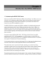
1.1 Introducing the BiPAC 5200 Series
Welcome to the Billion BiPAC 5200 Series ADSL2+ Modem/Router. Your Billion router is an
“all-in-one” unit, combining an ADSL modem, ADSL router and Ethernet network switch,
providing everything you need to get the machines on your network connected to the
Internet over your ADSL broadband connection.
The BiPAC 5200 Series complies with ADSL2+ standards for worldwide deployment and
supports downstream rates of up to 24 Mbps and upstream rates of up to 1 Mbps. It is
designed for small office, home office and residential users, enabling even faster speed
Internet connections. User can enjoy ADSL services and broadband multimedia applications
such as interactive gaming, video streaming and real-time audio much easier and faster
than ever before.
The product supports PPPoA (RFC 2364 – PPP (Point-to-Point Protocol) over ATM
Adaptation Layer 5), RFC 1483 encapsulation over ATM (bridged or routed), PPP over
Ethernet (RFC 2516), and IPoA (RFC1577) to establish a connection with ISP. The product
also supports VC-based and LLC-based multiplexing.
It is the perfect solution to connect a small group of PCs to a high-speed broadband Internet
connection. Multi-users can have high-speed Internet access simultaneously.
This product also serves as an Internet firewall, protecting your network from being
accessed by outside users. Not only provide the natural firewall function (Network Address
Translation, NAT), it also provides rich firewall features to secure user’s network. All
incoming data packets are monitored and filtered. Besides, it can also be configured to
block internal users from accessing to the Internet.
The product provides two levels of security support. First, it masks LAN users’ IP addresses
which are invisible to outside users on the Internet, making it much more difficult for a hacker
to target a machine on your network. Secondly, it can block and redirect certain ports to limit
the services that outside users can access. For example, to ensure that games and other
Internet applications will run properly, user can open some specific ports for outside users to
access internal services in network.
Integrated DHCP (Dynamic Host Control Protocol) services, client and server, allow multiple
users to get their IP addresses automatically on boot up from the product. Simply set local
machines as a DHCP client to accept a dynamically assigned IP address from DHCP server
and reboot. Each time local machine is powered up; the router will recognize it and assign
an IP address to instantly connect it to the LAN.
For advanced users, Virtual Service function allows the product to provide limited visibility to
local machines with specific services for outside users. An ISP (Internet Service Providers)
provided IP address can be set to the product and then specific services can be rerouted to
specific computers on the local network. For instance, a dedicated web server can be
connected to the Internet via the product and then incoming requests for HTML that are
received by the product can be rerouted to the dedicated local web server, even though the
server now has a different IP address. In this example, the product is on the Internet and
vulnerable to attacks, but the server is protected.
Virtual Server can also be used to re-task services to multiple servers. For instance, the
product can be set to allow separated FTP, Web, and Multiplayer game servers to share the
same Internet-visible IP address while still protecting the servers and LAN users from
hackers.
2
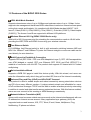
1.2 Features of the BiPAC 5200 Series
ADSL Multi-Mode Standard
Supports downstream rates of up to 24 Mbps and upstream rates of up to 1 Mbps. It also
supports rate management that allows ADSL subscribers to select an Internet access speed
suiting their needs and budgets. It is compliant with Multi-Mode standard (ANSI T1.413,
Issue 2; G.dmt(G.992.1); G.lite(G992.2)), G.hs (G994.1), G.dmt.bis (G.992.3), G.dmt.bisplus
(G.992.5)). The Annex A and B are supported in different H/W platforms.
Wireless Ethernet 802.11g (BiPAC 5200G Series only)
With built-in 802.11g access point for extending the communication media to WLAN while
providing the WEP, WPA and WPA2 for securing your wireless networks.
Fast Ethernet Switch
A 10/100Mbps fast Ethernet switch is built in with automatic switching between MDI and
MDI-X for 10Base-T and 100Base-TX ports. An Ethernet straight or cross-over cable can be
used directly for auto detection.
Multi-Protocol to Establish A Connection
Supports PPPoA (RFC 2364 - PPP over ATM Adaptation Layer 5), RFC 1483 encapsulation
over ATM (bridged or routed), PPP over Ethernet (RFC 2516) and IPoA (RFC1577) to
establish a connection with the ISP. The product also supports VC-based and LLC-based
multiplexing.
Quick Installation Wizard
Supports a WEB GUI page to install this device quickly. With this wizard, end users can
enter the information easily which they get from their ISP, then surf the Internet immediately.
Universal Plug and Play (UPnP) and UPnP NAT Traversal
This protocol is used to enable simple and robust connectivity among stand-alone devices
and PCs from many different vendors. It makes network simple and affordable for users.
UPnP architecture leverages TCP/IP and the Web to enable seamless proximity networking
in addition to control and data transfer among networked devices. With this feature enabled,
users can now connect to Net meeting or MSN Messenger seamlessly.
Network Address Translation (NAT)
Allows multi-users to access outside resources such as the Internet simultaneously with one
IP address/one Internet access account. Many application layer gateway (ALG) are
supported such as web browser, ICQ, FTP, Telnet, E-mail, News, Net2phone, Ping,
NetMeeting, IP phone and others.
3
Firewall
Supports simple firewall with NAT technology and provides option for blocking access from
Internet, like Telnet, FTP, WEB, SNMP and IGMP.
Domain Name System (DNS) relay
Provides an easy way to map the domain name (a friendly name for users such as
www.yahoo.com) and IP address. When a local machine sets its DNS server with this
router’s IP address, every DNS conversion request packet from the PC to this router will be
forwarded to the real DNS in the outside network.
Dynamic Domain Name System (DDNS)
The Dynamic DNS service allows you to alias a dynamic IP address to a static hostname.
This dynamic IP address is the WAN IP address. For example, to use the service, you must
first apply for an account from a DDNS service like http://www.dyndns.org/.
PPP over Ethernet (PPPoE)
Provides embedded PPPoE client function to establish a connection. Users can get greater
access speed without changing the operation concept, sharing the same ISP account and
paying for one access account. No PPPoE client software is required for local computer. The
Automatic Reconnect and Disconnect Timeout (Idle Timer) functions are provided, too.
Virtual Server
User can specify some services to be visible from outside users. The router can detect
incoming service request and forward it to the specific local computer to handle it. For
example, user can assign a PC in LAN acting as WEB server inside and expose it to the
outside network. Outside user can browse inside web server directly while it is protected by
NAT. A DMZ host setting is also provided to a local computer exposed to the outside network,
Internet.
Dynamic Host Configuration Protocol (DHCP) client and server
In the WAN site, the DHCP client can get an IP address from the Internet Service Provider
(ISP) automatically. In the LAN site, the DHCP server can allocate a range of client IP
addresses and distribute them including IP address, subnet mask as well as DNS IP
address to local computers. It provides an easy way to manage the local IP network.
RIP1/2 Routing
Supports RIP1/2 routing protocol for routing capability.
Simple Network Management Protocol (SNMP)
It is an easy way to remotely manage the router via SNMP.
Web based GUI
Supports web based GUI for configuration and management. It is user-friendly and comes
4
with on-line help. It also supports remote management capability for remote users to
configure and manage this product.
Firmware Upgradeable
Device can be upgraded to the latest firmware through the WEB based GUI.
5
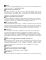
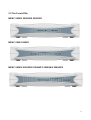
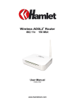
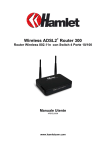
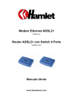
1.3 Applications for the BiPAC 5200 Series
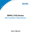
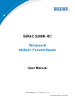
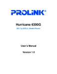
BiPAC 5200S/ 5200SR2/ 5200SR3
BiPAC 5200/ 5200R3
6
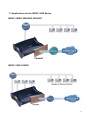
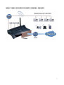
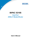
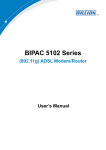
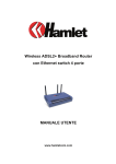
BiPAC 5200G/ 5200GR2/ 5200GR3/ 5200GR4/ 5200GR5
7
Chapter 2
Installing the BiPAC 5200 Series
2.1 Important note for using the BiPAC 5200 Series
Do not use the BiPAC 5200 Series in high humidity or high
temperatures.
Do not use the same power source for the BiPAC 5200 Series
as other equipment.
Warning
Do not open or repair the case yourself. If the BiPAC 5200
Series is too hot, turn off the power immediately and have it
repaired at a qualified service center.
Avoid using this product and all accessories outdoors.
Place the BiPAC 5200 Series on a stable surface.
Attention
Only use the power adapter that comes with the package. Using
a different voltage rating power adaptor may damage the router.
2.2 Package Contents
BiPAC 5200 Series ADSL2+ Router
CD-ROM containing the online manual
RJ-11 ADSL/telephone Cable (1.8M)
Ethernet (CAT-5 LAN) Cable (1.8M Straight)
AC-AC power adapter (12V AC, 1A): for 5200S/ 5200SR2/ 5200SR3/ 5200GR2/
5200GR3/ 5200GR4/ 5200GR5
AC-AD power adapter (12V DC, 1A): for 5200/5200R3/5200G
Quick Start Guide (105*150*mm)
8
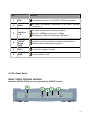
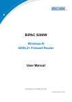
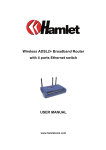
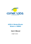
2.3 The Front LEDs
BiPAC 5200S/ 5200SR2/ 5200SR3
BiPAC 5200/ 5200R3
BiPAC 5200G/ 5200GR2/ 5200GR3/ 5200GR4/ 5200GR5
9
LED
Meaning
1
PPP :
Lit steady when there is a PPPoA / PPPoE connection.
2
ADSL:
Lit when successfully connected to an ADSL DSLAM
(“linesync”).
3
LAN Port
1-4:
Lit when connected to an Ethernet device.
Green for 100Mbps; Orange for 10Mbps.
Blinking when data is Transmitted / Received.
4
WLAN:
(5200G
Series
only)
Lit green when the wireless connection is established.
Flashes when sending/receiving data.
5
SYS :
Lit when the system is ready.
6
PWR :
Lit when power is ON.
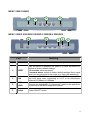
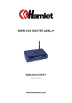
2.4 The Rear Ports
BiPAC 5200S/ 5200SR2/ 5200SR3
Attention: BiPAC 5200S has not supported the ON/OFF switch.
4
3
2
1
5
10
BiPAC 5200/ 5200R3
1
2
3
4
BiPAC 5200G/ 5200GR2/ 5200GR3/ 5200GR4/ 5200GR5
4
3
Port
2
1
5
Meaning
PWR
Connect the supplied power adapter to this jack.
2
RESET
After the device is powered on, press it to reset the device or
restore to factory default settings.
0-3 seconds: reset the device
6 seconds above: restore to factory default settings (this is used
when you can not login to the router, e.g. forgot the password)
3
LAN
Connect a UTP Ethernet cable (Cat-5 or Cat-5e) to one of the
four LAN ports when connecting to a PC or an office/home
network of 10Mbps or 100Mbps.
4
ADSL
(LINE)
Connect the supplied RJ-11 (“telephone”) cable to this port when
connecting to the ADSL/telephone network.
5
Power
Switch
Power ON/OFF switch
1
11
2.5 Cabling
One of the most common causes of problems is bad cabling or ADSL line(s). Make sure that
all connected devices are turned on. On the front of the product is a bank of LEDs. Verify that
the LAN Link and ADSL line LEDs are lit. If they are not, verify that you are using the proper
cables.
Ensure that all other devices connected to the same telephone line as your Billion router (e.g.
telephones, fax machines, analogue modems) have a line filter connected between them
and the wall socket (unless you are using a Central Splitter or Central Filter installed by a
qualified and licensed electrician), and ensure that all line filters are correctly installed and
the right way around. Missing line filters or line filters installed the wrong way around can
cause problems with your ADSL connection, including causing frequent disconnections
12
Chapter 3
Basic Installation
The router can be configured with your web browser. A web browser is included as a
standard application in the following operating systems: Windows 98/NT/2000/XP/Me, MAC,
Linux, etc. The product provides a very easy and user-friendly interface for configuration.
3.1 Before Configuration
PCs must have an Ethernet interface installed properly and be connected to the router either
directly or through an external repeater hub, and have TCP/IP installed and configured to
obtain an IP address through a DHCP server or a fixed IP address that must be in the same
subnet as the router. The default IP address of the router is 192.168.1.254 and the subnet
mask is 255.255.255.0 (i.e. any attached PC must be in the same subnet, and have an IP
address in the range of 192.168.1.1 to 192.168.1.253). The best and easiest way is to
configure the PC to get an IP address automatically from the router using DHCP. If you
encounter any problems accessing the router’s web interface it may also be advisable to
uninstall any kind of software firewall on your PCs, as they can cause problems accessing
the 192.168.1.254 IP address of the router. Users should make their own decisions on how
to best protect their network.
Please follow the steps below for your PC’s network environment installation. First of all,
please check your PC’s network components. The TCP/IP protocol stack and Ethernet
network adapter must be installed. If not, please refer to your Windows-related or other
operating system manuals.
Any TCP/IP capable workstation can be used to communicate with or
through the BiPAC 5200 Series. To configure other types of
workstations, please consult the manufacturer’s documentation.
13
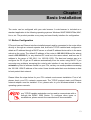
Configuring PC in Windows XP
1. Go to Start / Control Panel (in Classic
View). In the Control Panel, double-click
on Network Connections
2. Double-click Local Area Connection.
3. In the Local Area Connection Status
window, click Properties.
4. Select Internet Protocol (TCP/IP) and
click Properties.
5. Select the Obtain an IP address
automatically and the Obtain DNS
server address automatically radio
buttons.
6. Click OK to finish the configuration.
14
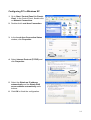
Configuring PC in Windows 2000
1. Go to Start / Settings / Control Panel.
In the Control Panel, double-click on
Network and Dial-up Connections.
2. Double-click Local Area Connection.
3. In the Local Area Connection Status
window click Properties.
4. Select Internet Protocol (TCP/IP) and
click Properties.
5. Select the Obtain an IP address
automatically and the Obtain DNS
server address automatically radio
buttons.
6. Click OK to finish the configuration.
15
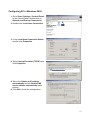
Configuring PC in Windows 98/Me
1.Go to Start / Settings / Control Panel.
In the Control Panel, double-click on
Network and choose the
Configuration tab.
2.Select TCP/IP ->NE2000 Compatible,
or the name of your Network Interface
Card (NIC) in your PC.
3.Select the Obtain an IP address
automatically radio button.
4.Then select the DNS Configuration tab.
5.Select the Disable DNS radio button
and click OK to finish the configuration.
16
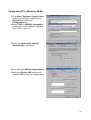
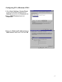
Configuring PC in Windows NT4.0
1. Go to Start / Settings / Control Panel.
In the Control Panel, double-click on
Network and choose the Protocols tab.
2.Select TCP/IP Protocol and click
Properties.
3.Select the Obtain an IP address from a
DHCP server radio button and click OK.
17
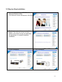
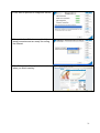
3.2 Step-by-Step Installation
1.
2.
3.
Insert the CD-ROM into CD-ROM drive
Execute Windows Utility
The Welcome screen will appear, click Next
4. The Hardware Installation screen will
appear. Four links are shown on the
screen. Click them one by one and follow
the guidelines to complete hardware
installation.
4.1 Power connection
4.2 LAN connection
18
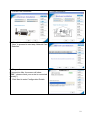
4.3 ADSL Line connection
4.4 Filter connection
5. When finished Hardware Installation, click
“Next” to proceed to next step, Network Card
Selection.
6. Diagnostic screen.
(If connection fails, the screen will show
“FAIL” ,please check your router is connected
correctly.)
7. Click Next to enter Configuration Details
19
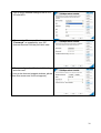
8. Set up more detailed settings such as VPI,
VCI and MTU.
9. Please enter “Username” and
“Password” as supplied by your ISP
(Internet Service Provider) and click next.
10. Please configure the Wireless LAN setting
and click next.
(If your router does not support wireless, please
ignore this screen and it will not appear.)
20
11. Click Next to proceed to Diagnostic screen
12. Congratulations!! You’ve completed the
setup procedure and are ready for surfing
the Internet.
13. The IE browser will be opened automatically
when you finish installing.
21
3.3 Factory Default Settings
Before configuring your, you need to know the following default settings.
Web Interface:
Username: admin
Password: admin
LAN Device IP Settings:
IP Address: 192.168.1.254
Subnet Mask: 255.255.255.0
ISP setting in WAN site:
PPPoE
DHCP server:
DHCP server is enabled.
Start IP Address: 192.168.1.100
IP pool counts: 100
3.3.1 Username and Password
The default username and password are “admin” and “admin” respectively.
If you ever forget the password to log in, you may press the RESET
button up to 6 seconds to restore the factory default settings.
Attention
Attention
22
3.4 LAN and WAN Port Addresses
The parameters of LAN and WAN ports are pre-set in the factory. The default values are
shown below.
LAN Port
IP address
192.168.1.254
Subnet Mask
255.255.255.0
DHCP server function
Enabled
IP addresses for
distribution to PCs
100 IP addresses continuing from
192.168.1.100 through
192.168.1.199
WAN Port
The PPPoE function is
enabled to
automatically get the
WAN port
configuration from the
ISP, but you have to
set the username and
password first.
3.5 Information from your ISP
Before configuring this device, you have to check with your ISP (Internet Service Provider)
what kind of service is provided such as PPPoE, PPPoA, RFC1483, or IPoA.
Gather the information as illustrated in the following table and keep it for reference.
PPPoE
VPI/VCI, VC-based/LLC-based multiplexing, Username, Password,
Service Name, and Domain Name System (DNS) IP address (it can
be automatically assigned by your ISP when you connect or be set
manually).
PPPoA
VPI/VCI, VC-based/LLC-based multiplexing, Username, Password,
and Domain Name System (DNS) IP address (it can be
automatically assigned by your ISP when you connect or be set
manually).
RFC1483 Bridged
VPI/VCI, VC-based/LLC-based multiplexing to use Bridged Mode.
RFC1483 Routed
VPI/VCI, VC-based/LLC-based multiplexing, IP address, Subnet
mask, Gateway address, and Domain Name System (DNS) IP
address (it is fixed IP address).
23
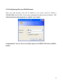
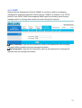
3.6 Configuring with your Web Browser
Open your web browser, enter the IP address of your router, which by default is
192.168.1.254, and click “Go”, a user name and password window prompt will appear. The
default username and password are “admin” and “admin”.
Congratulation! You are now successfully logon to the BiPAC 5200 Series ADSL2+
Router!
24
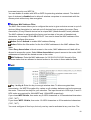
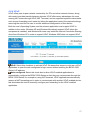
Chapter 4
Configuration
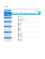
At the configuration homepage, the left navigation pane where bookmarks are provided links
you directly to the desired setup page, including:
Quick Start (wizard setup)
Interface Setup (Internet, LAN, Wireless)
Advanced Setup (Firewall, Routing, NAT, ADSL)
Access Management (ACL, Filter, SNMP, UPnP, DDNS)
Maintenance (Administration, Time Zone, Firmware, SysRestart, Diagnositics)
Status (Device Info, System Log, Statistics)
Help
Please see the relevant sections of this manual for detailed instructions on how to configure
your Billion router.
25
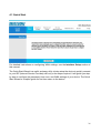
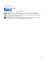
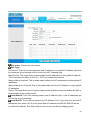
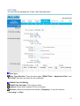
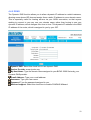
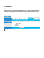
4.1 Quick Start
For detailed instructions on configuring WAN settings, see the Interface Setup section of
this manual.
The Quick Start Wizard is a useful and easy utility to help setup the device to quickly connect
to your ISP (Internet Service Provider) with only a few steps required. It will guide you step
by step to configure the password, time zone, and WAN settings of your device. The Quick
Start Wizard is a helpful guide for first time users to the device.
26
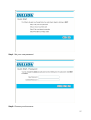
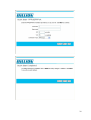
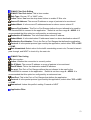
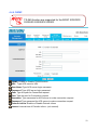
Step1. Set your new password.
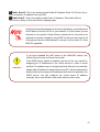
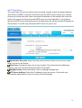
Step2: Choose your time zone
27
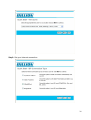
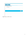
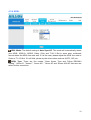
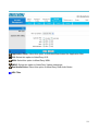
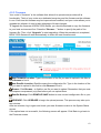
Step3: Set your Internet connection
28
29
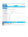
Step4: Restart your ADSL2+ Router
30
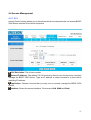
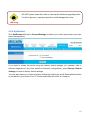
4.2 Interface Setup
Click this item to access the following sub-items that configure the ADSL2+ router: Internet,
LAN, and Wireless
These functions are described in the following sections.
31
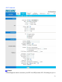
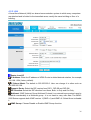
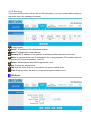
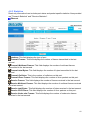
4.2.1 Internet
ATM VC
ATM settings are used to connect to your ISP. Your ISP provides VPI, VCI settings to you. In
32
this Device, you can totally setup 8 VCs on different encapsulations, if you apply 8 different
virtual circuits from your ISP. You need to activate the VC to take effect. For PVCs
management, you can use ATM QoS to setup each PVC traffic line's priority.
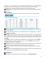
Virtual Circuit: VPI (Virtual Path Identifier) and VCI (Virtual Channel Identifier) define a
virtual circuit.
PVC Summary:
VPI: The valid range for the VPI is 0 to 255. Enter the VPI assigned to you. This field may
already be configured.
VCI: The valid range for the VCI is 1 to 65535. Enter the VCI assigned to you. This field
may already be configured.
ATM QoS: Select the Quality of Service types for this Virtual Circuit. The ATM QoS types
include CBR (Constant Bit Rate), VBR (Variable Bit Rate) and UBR (Unspecified Bit Rate).
These QoS types are all controlled by the parameters specified below, including PCR, SCR
and MBS.
Select CBR to specify fixed (always-on) bandwidth for voice or data traffic. Select UBR for
applications that are non-time sensitive, such as e-mail. Select VBR for burst traffic and
bandwidth sharing with other applications.
PCR: Divide the DSL line rate (bps) by 424 (the size of an ATM cell) to find the Peak Cell
Rate (PCR). This is the maximum rate at which the sender can send cells.
SCR: The Sustain Cell Rate (SCR) sets the average cell rate (long-term) that can be
transmitted.
MBS: Maximum Burst Size (MBS) refers to the maximum number of cells that can be sent
at the peak rate. Type the MBS, which is less than 65535
Encapsulation:
ISP: Select the encapsulation type your ISP uses from the Encapsulation list.
33
Choices vary depending on what you select in the Mode field.
Dynamic IP: Select this option if your ISP provides you an IP address automatically. This
option is typically used for Cable services. Please enter the Dynamic IP information
accordingly.
Static IP: Select this option to set static IP information. You will need to enter in the
Connection type, IP address, subnet mask, and gateway address, provided to you by your
ISP. Each IP address entered in the fields must be in the appropriate IP form, which is four IP
octets separated by a dot (x.x.x.x). The Router will not accept the IP address if it is not in this
format.
PPPoE/PPPoA: Select this option if your ISP requires you to use a PPPoE connection. This
option is typically used for DSL services. Select Dynamic PPPoE to obtain an IP address
automatically for your PPPoE connection. Select Static PPPoE to use a static IP address for
your PPPoE connection. Please enter the information accordingly.
PPPoE/PPPoA
Select this option if your ISP requires you to use a PPPoE connection. This option is typically
used for DSL services. Select Dynamic PPPoE to obtain an IP address automatically for
your PPPoE connection. Select Static PPPoE to use a static IP address for your PPPoE
connection. Please enter the information accordingly.
User Name: Enter the user name exactly as your ISP assigned.
Password: Enter the password associated with the user name above.
Encapsulation: select Bridge in the Mode field, select either PPPoA or RFC 1483.
select Routing in the Mode field, select PPPoA, RFC 1483, ENET ENCAP or PPPoE.
Multiplex: Select the method of multiplexing used by your ISP. Choices are VC or LLC.
Half Bridge: The Half Bridge mode can only be used when a single IP address has been
assigned by the ISP. It is used when the use of NAT is not desired and there is a single
computer attached to the router.
Connection: The schedule rule(s) have priority over your Connection settings.
Always on: Select Always on Connection when you want your connection up all the time.
Connect on Demand: Select Connect on Demand when you don't want the connection up
all the time and specify an idle time-out in the Max Idle Timeout field
TCP MSS Option: Enter the TCP Maximum Segment Size (MSS)
Get IP Address: Choose Static or Dynamic
Static IP Address: Enter the IP address of ADSL Router in dotted decimal notation, for
example, 192.168.1.254 (factory default).
IP Subnet Mask: The default is 0.0.0.0. User can change it to other such as
255.255.255.0.Type the subnet mask assigned to you by your ISP (if given).
Gateway: You must specify a gateway IP address (supplied by your ISP) when you use
34
1483 Bridged IP in the Encapsulation field in the previous screen.
NAT: Select this option to Activate/Deactivated the NAT (Network Address Translation)
function for this VC. The NAT function can be activated or deactivated per PVC basis
Default Route: if enable this function, the current PVC will be the default gateway to
internet from this device
TCP MTU Option: Enter the TCP maximum transmission unit (MTU)
Dynamic Route:
RIP Version: (Routing Information protocol) Select this option to specify the RIP version,
including RIP-1, RIP-2M and RIP-2B. RIP-2M and RIP-2B are both sent in RIP-2 format; the
difference is that RIP-2M using Multicast and RIP-2 using Broadcast format
RIP Direction: Select this option to specify the RIP direction. None is for disabling the RIP
function. Both means the ADSL Router will periodically send routing information and accept
routing information then incorporate into routing table. IN only means the ADLS router will
only accept but will not send RIP packet. OUT only means the ADLS router will only send but
will not accept RIP packet.
Multicast: IGMP (Internet Group Multicast Protocol) is a network-layer protocol used to
establish membership in a Multicast group - it is not used to carry user data. The BiPAC
5200 Series supports both IGMP version 1 (IGMP-v1) and IGMP-v2. Select None to disable
it
35
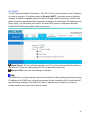
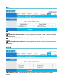
4.2.2 LAN
A Local Area Network (LAN) is a shared communication system to which many computers
are attached and is limited to the immediate area, usually the same building or floor of a
building.
Router Local IP
IP Address: Enter the IP address of ADSL Router in dotted decimal notation, for example,
192.168.1.254 (factory default).
IP Subnet Mask: The default is 255.255.255.0. User can change it to other such as
255.255.255.128.
Dynamic Route: Select the RIP version from RIP-1, RIP-2B and RIP-2M.
RIP Direction: Select the RIP direction from None, Both, In Only and Out Only.
Multicast: IGMP (Internet Group Multicast Protocol) is a network-layer protocol used to
establish membership in a Multicast group - it is not used to carry user data. The BiPAC
5200 Series supports both IGMP version 1 (IGMP-v1) and IGMP-v2. Select None to disable
it
IGMP Snoop: Choose Disable or Enable IGMP Snoop function.
36
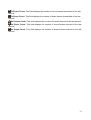
DHCP
DHCP (Dynamic Host Configuration Protocol, RFC 2131 and RFC 2132) allows individual
clients to obtain TCP/IP configuration at start-up from a server.
DHCP:
If set to Enable, your BiPAC 5200 Series can assign IP addresses, an IP default gateway
and DNS servers to Windows 95, Windows NT and other systems that support the DHCP
client.
If set to disabled, the DHCP server will be disabled.
If set to Relay, the BiPAC 5200 Series acts as a surrogate DHCP server and relays DHCP
requests and responses between the remote server and the clients. Enter the IP address of
the actual, remote DHCP server in the Remote DHCP Server field in this case.
When DHCP is used, the following items need to be set.
Starting IP Address: This field specifies the first of the contiguous addresses in the IP
address pool.
IP Pool Count: This field specifies the size or count of the IP address pool.
Lease Time: The current lease time of client.
Primary DNS Server: Enter the IP addresses of the DNS servers. The DNS servers are
passed to the DHCP clients along with the IP address and the subnet mask.
Secondary DNS Server: Enter the IP addresses of the DNS servers. The DNS servers
are passed to the DHCP clients along with the IP address and the subnet mask.
37
4.2.3 Wireless
802.11g are only supported for the BiPAC 5200G Series.
This section introduces the wireless LAN and some basic configurations. Wireless LANs can
be as simple as two computers with wireless LAN cards communicating in a peer-to-peer
network or as complex as a number of computers with wireless LAN cards communicating
through access points which bridge network traffic to the wired LAN.
38
Access Point Settings
Access Point: Default setting is set to Activated. If you do not have any wireless, both
802.11g and 802.11b, device in your network, select Deactived.
Channel ID: The range of radio frequencies used by IEEE 802.11b/g wireless devices is
called a channel. Select a channel from the drop-down list box.
Beacon interval: The Beacon Interval value indicates the frequency interval of the
beacon. Enter a value between 20 and 1000. A beacon is a packet broadcast by the Router
to synchronize the wireless network.
RTS/CTS Threshold: The RTS (Request To Send) threshold (number of bytes) for
enabling RTS/CTS handshake. Data with its frame size larger than this value will perform
the RTS/CTS handshake. Setting this attribute to be larger than the maximum MSDU (MAC
service data unit) size turns off the RTS/CTS handshake. Setting this attribute to zero turns
on the RTS/CTS handshake Enter a value between 1500 and 2347..
Fragmentation Threshold: The threshold (number of bytes) for the fragmentation
boundary for directed messages. It is the maximum data fragment size that can be sent.
Enter a value between 256 and 2346.
DMIT: This value, between 1 and 255, indicates the interval of the Delivery Traffic
Indication Message (DTIM).
802.11b/g: The default setting is 802.11b+g (Mixed mode). If you do not know or have
both 11g and 11b devices in your network, then keep the default in mixed mode. From the
drop-down manual, you can select 802.11g if you have only 11g card. If you have only 11b
card, then select 802.11b.
SSIDs Setting
SSID Index: Default SSID index is “1”.
SSID: The SSID is the unique name of a wireless access point (AP) to be distinguished
from another. For security propose, change the default wlan-ap to a unique ID name to the
AP which is already built-in to the router’s wireless interface. It is case sensitive and must
not excess 32 characters. Make sure your wireless clients have exactly the SSID as the
device, in order to get connected to your network.
Broadcast SSID: Select Yes to hide the SSID in so a station cannot obtain the SSID
through passive scanning. Select No to make the SSID visible so a station can obtain the
SSID through passive scanning.
Authentication Type: To prevent unauthorized wireless stations from accessing data
transmitted over the network, the router offers highly secure data encryption, known as
WEP.&WPA. If you require high security for transmissions, there are four alternatives to
select from: 64-bit WEP, 128-bit WEP, WPA-PSK and WPA2-PSK. WEP 128 will offer
39
increased security over WEP 64.
You can disable or enable with WPA or WEP for protecting wireless network. The default
type of wireless is disabled and to allow all wireless computers to communicate with the
access points without any data encryption
Wireless MAC Address Filter
The MAC filter screen allows you to configure the router to give exclusive access to up to 8
devices (Allow Association) or exclude up to 8 devices from accessing the router (Deny
Association). Every Ethernet device has a unique MAC (Media Access Control) address.
The MAC address is assigned at the factory and consists of six pairs of hexadecimal
characters, for example, 00:AA:BB:00:00:02. You need to know the MAC address of the
devices to configure this screen.
Active: Select Actived to enable MAC address filtering.
Action: Define the filter action for the list of MAC addresses in the MAC address filter
table.
Select Deny Association to block access to the router, MAC addresses not listed will be
allowed to access the router. Select Allow Association to permit access to the router, MAC
addresses not listed will be denied access to the router.
MAC Address: Enter the MAC addresses (in XX:XX:XX:XX:XX:XX format) of the
wireless station that are allowed or denied access to the router in these address fields.
WEP
Key 1 to Key 4: Enter the key to encrypt wireless data. To allow encrypted data
transmission, the WEP Encryption Key values on all wireless stations must be the same as
the router. There are four keys for your selection. The input format is in HEX style, 5 and 13
HEX codes are required for 64-bitWEP and 128-bitWEP respectively.
If you chose WEP 64-bits, then enter any 5 ASCII characters or 10 hexadecimal characters
("0-9", "A-F").
If you chose WEP 128-bits, then enter 13 ASCII characters or 26 hexadecimal characters
("0-9", "A-F").
You must configure all four keys, but only one key can be activated at any one time. The
40
default key is key 1.
WPA-PSK & WPA2-PSK
Encryption: TKIP (Temporal Key Integrity Protocol) or AES (Advanced Encryption
System) utilizes a stronger encryption method and incorporates Message Integrity Code
(MIC) to provide protection against hackers.
Pre-Shared key: The key for network authentication. The input format is in character
style and key size should be in the range between 8 and 63 characters.
41
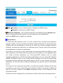
4.3 Advanced Setup
4.3.1 Firewall
Your router includes a firewall for controlling Internet access from your LAN and helping to
prevent attacks from hackers. In addition to this, when using NAT (Network Address
Translation) the router acts as a “natural” Internet firewall, since all PCs on your LAN use
private IP addresses that cannot be directly accessed from the Internet.
Firewall:
Enabled: As set in default setting, it activates your firewall function.
Disabled: It disables the firewall function.
SPI:
Enabled: As set in default setting, it activates your SPI function.
Disabled: It disables the SPI function.
42
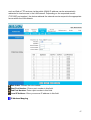
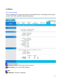
4.3.2 Routing
If you have another router with a LAN-to-LAN connection, you may create a static routing on
the router that is the gateway to Internet.
#: Item number
Dest IP: IP address of the destination network
Mask: The destination mask address.
Gateway IP: IP address of the gateway or existing interface that this route uses.
Metric: It represents the cost of transmission for routing purposes. The number need not
be precise, but it must be between 1 and 15.
Device: Media/channel selected to append the route.
Use: Counter for access times.
Edit: Edit the route; this icon is not shown for system default route.
Drop: Drop the route; this icon is not shown for system default route.
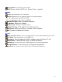
ADD Route
43
Destination IP Address:This is the destination subnet IP address.
IP Subnet Mask:It is the destination IP addresses based on above destination subnet IP
Gateway IP Address:This is the gateway IP address to which packets are to be
forwarded.
Metric:It represents the cost of transmission for routing purposes. The number need not
be precise, but it must be between 1 and 15.
Announced in RIP: This parameter determines if the Prestige will include the route to the
remote node in its RIP broadcasts. Set “No”, it is kept private and is not included in RIP
broadcasts. Set “Yes”, the remote node will be propagated to other hosts through RIP
broadcasts.
44
4.3.3 NAT
The NAT (Network Address Translation - NAT, RFC 1631) is the translation of the IP address
of a host in a packet. The default setting is Dynamic NAPT. It provides dynamic Network
Address Translation capability between LAN and multiple WAN connections, and the LAN
traffic is routed to appropriate WAN connections based on the destination IP addresses and
Route Table. This eliminates the need for the static NAT session configuration between
multiple LAN clients and multiple WAN connections.
Virtual Circuit: VPI (Virtual Path Identifier) and VCI (Virtual Channel Identifier) define a
virtual circuit. There are eight groups of PVC can be defined and used.
Number of IPs: User can select Single or Multiple.
DMZ
The DMZ Host is a local computer exposed to the Internet. When setting a particular internal
IP address as the DMZ Host, all incoming packets will be checked by the Firewall and NAT
algorithms then passed to the DMZ host, when a packet received does not use a port
number used by any other Virtual Server entries.
45
DMZ:
Disabled: As set in default setting, it disables the DMZ function.
Enabled: It activates your DMZ function.
DMZ Host IP Address: Give a static IP address to the DMZ Host when Enabled radio
button is checked. Be aware that this IP will be exposed to the WAN/Internet.
Select the SAVE button to apply your changes.
Virtual Server
In TCP/IP and UDP networks a port is a 16-bit number used to identify which application
program (usually a server) incoming connections should be delivered to. Some ports have
numbers that are pre-assigned to them by the IANA (the Internet Assigned Numbers
Authority), and these are referred to as “well-known ports”. Servers follow the well-known
port assignments so clients can locate them.
If you wish to run a server on your network that can be accessed from the WAN (i.e. from
other machines on the Internet that are outside your local network), or any application that
can accept incoming connections (e.g. Peer-to-peer/P2P software such as instant
messaging applications and P2P file-sharing applications) and are using NAT (Network
Address Translation), then you will usually need to configure your router to forward these
incoming connection attempts using specific ports to the PC on your network running the
application. You will also need to use port forwarding if you want to host an online game
server.
The reason for this is that when using NAT, your publicly accessible IP address will be used
by and point to your router, which then needs to deliver all traffic to the private IP addresses
used by your PCs. Please see the WAN configuration section of this manual for more
information on NAT.
The device can be configured as a virtual server so that remote users accessing services
46
such as Web or FTP services via the public (WAN) IP address can be automatically
redirected to local servers in the LAN network. Depending on the requested service
(TCP/UDP port number), the device redirects the external service request to the appropriate
server within the LAN network.
Rule Index: Choose the rule number.
Start Port Number: Enter a port number in this field.
End Port Number: Enter a port number in this field.
Local IP Address: Enter your server IP address in this field.
IP Address Mapping
47
Rule Index: Choose the rule number.
Rule Type:
One-to-one: This is the mode maps one local IP address to one global IP address. Note that
port numbers do not change for the One-to-one NAT mapping type.
Many-to-One: This is the mode maps multiple local IP addresses to one global IP address.
This is equivalent to Many to One (i.e., PAT, port address translation).
Many-to-Many Overload: This is mode maps multiple local IP addresses to shared global IP
addresses.
Many-to-Many No Overload: This is the mode maps each local IP address to unique global
IP addresses.
Server: This type allows you to specify inside servers of different services behind the NAT to
be accessible to the outside world.
Local Start IP: This is the starting Inside Local IP Address (ILA). Local IP addresses are
N/A for Server port mapping.
Local End IP: This is the end Inside Local IP Address (ILA). If your rule is for all local IP
addresses, then enter 0.0.0.0 as the Local Start IP address and 255.255.255.255 as the
Local End IP address. This field is N/A for One-to-one and Server mapping types.
48
Public Start IP: This is the starting Inside Public IP Address. Enter 0.0.0.0 here if you
have a dynamic IP address from your ISP.
Public End IP: This is the ending Inside Public IP Address. This field is N/A for
One-to-one, Many-to-One and Server mapping types.
Using port forwarding does have security implications, as outside users
will be able to connect to PCs on your network. For this reason you are
advised to use specific Virtual Server entries just for the ports your
application requires, instead of using DMZ. As doing so will result in all
connections from the WAN attempt to access to your public IP of the
DMZ PC specified.
Attention
If you have disabled the NAT option in the WAN-ISP section, the
Virtual Server function will hence be invalid.
If the DHCP server option is enabled, you have to be very careful in
assigning the IP addresses of the virtual servers in order to avoid
conflicts. The easiest way of configuring Virtual Servers is to manually
assign static IP address to each virtual server PC, with an address that
does not fall into the range of IP addresses that are to be issued by the
DHCP server. You can configure the virtual server IP address
manually, but it must still be in the same subnet as the router.
49
4.3.4 ADSL
ADSL Mode: The default setting is Auto Sync-UP. This mode will automatically detect
your ADSL, ADSL2+, ADSL2, G.dmt, G.lite, and T1.413. But in some area, multimode
cannot detect the ADSL line code well. If it is the case, please adjust the ADSL line code to
G.dmt or T1.413 first. If it still fails, please try the other values such as ALCTL, ADI, etc.
ADSL Type: There are five modes “Open Annex Type and Follow DSLAM’s
Setting”, ”Annex A”, ”Annex I”, “Annex A/L”, ”Annex M” and “Annex A/I/L/M” that user can
select for this connection.
50
4.4 Access Management
4.4.1 ACL
Access Control Listing allows you to determine which services/protocols can access BiPAC
5200 Series interface from which computers.
ACL Rule Index: This is item number
Secure IP Address: The default 0.0.0.0 allows any client to use this service to remotely
manage the BiPAC 5200 Series. Type an IP address to restrict access to a client with a
matching IP address.
Application: Choose a service that you may use to remotely manage the BiPAC 5200
Series.
Interface: Select the access interface. Choices are LAN, WAN and Both.
51
4.4.2 Filter
You can Filter the packages by IP port , MAC and Application.
Filter Type
Filter Type Selection: There are three types ”IP/MAC Filter”, ”Application Filter”, and
“URL Filter” that user can select for this connection.
IP/MAC Filter Set Editing
IP/MAC filter Set Index: This is item number
Interface: Select which channel (PVC) to configure.
Direction: Select the access to the Internet (“Outgoing”) or from the Internet
(“Incoming”).or Both.
52
IP/MAC Filter Rule Editing
IP/MAC Filter Rule Index: This is item number
Rule Type: Choose “IP” or “MAC” rules
Active: Select Yes from the drop down list box to enable IP filter rule.
Source IP Address: The source IP address or range of packets to be monitored.
Subnet Mask: It is the source IP addresses based on above source subnet IP
Source Port Number: This Port or Port Ranges defines the port allowed to be used by
the Remote/WAN to connect to the application. Default is set from range 0 ~ 65535. It is
recommended that this option be configured by an advanced user.
Destination IP Address: This is the destination subnet IP address.
Subnet Mask: It is the destination IP addresses based on above destination subnet IP
Destination Port Number: This is the Port or Port Ranges that defines the application.
Protocol: It is the packet protocol type used by the application, select either TCP or UDP
or ICMP
Rule Unmatched: Select action for the traffic unmatching current rule; Forward to leave it
pass through, and NEXT to check it by the next rule.
IP/MAC Filter Listing
#: Item number.
Active: Whether the connection is currently active.
Src IP Mask: The source IP address or range of packets to be monitored.
Dest IP Mask: This is the destination subnet IP address.
Src port: This Port or Port Ranges defines the port allowed to be used by the
Remote/WAN to connect to the application. Default is set from range 0 ~ 65535. It is
recommended that this option be configured by an advanced user.
Dest Port: This is the Port or Port Ranges that defines the application.
Protocol: It is the packet protocol type used by the application, select either TCP or UDP
or ICMP
Unmatched: It show this profile’s setting :Forward or NEXT
Application Filter
53
Application Filter: Select this option to Activated/Deactivated the Application filter.
ICQ: Select this option to Allow/Deny ICQ.
MSN: Select this option to Allow/Deny MSN.
YMSG: Select this option to Allow/Deny Yahoo messenger.
Real Audio/Video: Select this option to Allow/Deny Real Audio/Video.
URL Filter
54
Active: Select Actived to enable URL Filter.
URL Index: This is item number.
URL: Allow you to prevent users on your network from accessing particular websites by
their URL.
55
4.4.3 SNMP
Simple Network Management Protocol (SNMP) is a protocol used for exchanging
management information between network devices. SNMP is a member of the TCP/IP
protocol suite. BiPAC 5200 Series supports SNMP agent functionality which allows a
manager station to manage and monitor the router through the network.
Get Community: Type the Get Community, which is the password for the incoming
Get-and GetNext requests from the management station.
Set Community: Type the Set Community, which is the password for incoming Set
requests from the management station.
56
4.4.4 UPnP
UPnP offers peer-to-peer network connectivity for PCs and other network devices, along
with control and data transfer between devices. UPnP offers many advantages for users
running NAT routers through UPnP NAT Traversal, and on supported systems makes tasks
such as port forwarding much easier by letting the application control the required settings,
removing the need for the user to control advanced configuration of their device.
Both the user’s Operating System and the relevant application must support UPnP in
addition to the router. Windows XP and Windows Me natively support UPnP (when the
component is installed), and Windows 98 users may install the Internet Connection Sharing
client from Windows XP in order to support UPnP. Windows 2000 does not support UPnP.
UPnP: Select this checkbox to activate UPnP. Be aware that anyone could use a UPnP
application to open the web configurator's login screen without entering the BiPAC 5200
Series 's IP address
Auto-configured: Select this check box to allow UPnP-enabled applications to
automatically configure the BiPAC 5200 Series so that they can communicate through the
BiPAC 5200 Series, for example by using NAT traversal, UPnP applications automatically
reserve a NAT forwarding port in order to communicate with another UPnP enabled device;
this eliminates the need to manually configure port forwarding for the UPnP enabled
application.
57
4.4.5 DDNS
The Dynamic DNS function allows you to alias a dynamic IP address to a static hostname,
allowing users whose ISP does not assign them a static IP address to use a domain name.
This is especially useful for hosting servers via your ADSL connection, so that anyone
wishing to connect to you may use your domain name, rather than having to use your
dynamic IP address, which changes from time to time. This dynamic IP address is the WAN
IP address of the router, which is assigned to you by your ISP.
Dynamic DNS: Select this check box to use dynamic DNS.
Service Provider: www.dyndns.org
My Host Name: Type the domain name assigned to your BiPAC 5200 Series by your
Dynamic DNS provider.
E-mail Address: Type your e-mail address.
Username: Type your user name.
Password: Type the password assigned to you.
Wildcard support: Select this check box to enable DYNDNS Wildcard.
58
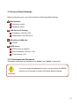
4.4.6 CWMP
TR-069 function are supported for the BiPAC 5200GR3/
5200GR5 /5200SR3/ 5200R3.
CWMP: Enable or Disable TR069 function
URL: Type ACS server’s URL
User Name:Type ACS server login username
Password: Type ACS server login password
Path: Type the path for Connection request
Port: Type the port for Connection request
Username: Type username for ACS server to make connection request
Password: Type password for ACS server to make connection request
Periodic inform: Enable or Disable Periodic inform
Interval: interval time of Periodic inform (unit second).
59
4.5 Maintenance
4.5.1 Administrator
In factory setting, the default password is admin, and that for user is also password. You can
change the default password to ensure that someone cannot adjust your settings without
your permission. Every time you change your password, please record the password and
keep it at a safe place.
New Password: Type the new password in this field
Confirm Password: Type the new password again in this field.
60
4.5.2 Time Zone
The router does not have a real time clock on board; instead, it uses the Simple Network
Time Protocol (SNTP) to get the current time from an SNTP server outside your network.
Choose your local time zone. After a successful connection to the Internet, the router will
retrieve the correct local time from the SNTP server you have specified. If you prefer to
specify an SNTP server other than those in the drop-down list, simply enter its IP address as
shown above. Your ISP may provide an SNTP server for you to use.
Synchronize time with: Select the time service protocol that your time server sends
when you turn on the Router.
Time Zone: Choose the time zone of your location. This will set the time difference
between your time zone and Greenwich Mean Time (GMT).
Daylight Saving: Select this option if you use daylight savings time
NTP Server Address: Enter the IP address of your time server. Check with your
ISP/network administrator if you are unsure of this information.
61
4.5.3 Firmware
Your router’s “firmware” is the software that allows it to operate and provides all its
functionality. Think of your router as a dedicated computer, and the firmware as the software
it runs. Over time this software may be improved and modified, and your router allows you to
upgrade the software it runs to take advantage of these changes.
To upgrade the firmware of BiPAC 5200 Series, you should download or copy the firmware
to your local environment first. Press the “Browse…” button to specify the path of the
firmware file. Then, click “Upgrade” to start upgrading. When the procedure is completed,
BiPAC 5200 Series will reset automatically to make the new firmware work.
New Firmware Location: Type in the location of the file you want to upload in this field or
click Browse to find it.
New Romfile Location: Romfile means the configuration file. Type in the location of the
file you want to upload in this field or click Browse to find it.
Browse: Click Browse... to find the .ras file you want to upload. Remember that you must
decompress compressed (.zip) files before you can upload them.
Romfile Backup: Click ROMFILE SAVE button to save current configuration file to your
PC.
UPGRADE: Click UPGRADE to begin the upload process. This process may take up to
two minutes.
After two minutes, log in again and check your new firmware version in the System Status
screen.
If the upload was not successful, the following screen will appear. Click Back to go back to
the Firmware screen.
62
DO NOT power down the router or interrupt the firmware upgrading while
it is still in process. Improper operation could damage the router.
Warning
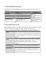
4.5.4 SysRestart
Click SysRestart with option Current Settings to reboot your router (and restore your last
saved configuration).
If you wish to restart the router using the factory default settings (for example, after a
firmware upgrade or if you have saved an incorrect configuration), select Factory Default
Settings to reset to factory default settings.
You may also reset your router to factory settings by holding the small Reset pinhole button
on the back of your router in for 10-12 seconds whilst the router is turned on.
63
4.5.5 Diagnostics
The Diagnostic Test page shows the test results for the connectivity of the physical layer and
protocol layer for both LAN and WAN sides
64
4.6 Status
4.6.1 Device Info
This page displays the current information for the ADSL Router. It will display the Firmware
version, LAN, WAN, and MAC address information.
Device Information
Firmware version: This is the Firmware version
MAC Address: This is the MAC Address
LAN
IP Address: LAN port IP address.
65
Sub Net Mask: LAN port IP subnet mask.
DHCP Server: LAN port DHCP role - Enabled, Relay or disabled
WAN
Status: “Not connected” or “Connected”
Virtual Circuit: There are eight groups of PVC can be defined.
VPI: The valid range for the VPI is 0 to 255
VCI: The valid range for the VCI is 1 to 65535
Connection Type: Name of the WAN connection.
IP Address: WAN port IP address.
Subnet mask: WAN port IP subnet mask.
Default Gateway: The IP address of the default gateway.
DNS Server: WAN port DHCP role - Enabled, Relay or disabled
NAT: Enabled or Disabled NAT function
ADSL
ADSL firmware version: This is the DSL firmware version associated with your router
Line State: This is the status of your ADSL link.
Modulation: This field displays the ADSL modulation status for G.dmt or T1.413.
Annex Mode: To show the router’s type, e.g. Annex A, Annex B
SNR Margin: To show the router’s SNR margin for Downstream/Upstream
Line Attenuation : To show the router’s for Downstream/Upstream
Data Rate: To show the router’s data rate for Downstream/Upstream
66
4.6.2 System Log
Display system logs accumulated up to the present time. You can trace historical information
with this function.
67
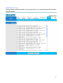
4.6.3 Statistics
Read-only information here includes port status and packet specific statistics. Also provided
are "Transmit Statistics" and "Receive Statistics".
Ethernet
Interface: This field displays the type of port
Transmit Frames: This field displays the number of frames transmitted in the last
second.
Transmit Multicast Frames: This field displays the number of multicast frames
transmitted in the last second.
Transmit total Bytes: This field displays the number of bytes transmitted in the last
second.
Transmit Collision: This is the number of collisions on this port.
Transmit Error Frames: This field displays the number of error packets on this port.
Receive Frames: This field displays the number of frames received in the last second.
Receive Multicast Frames: This field displays the number of multicast frames received
in the last second.
Receive total Bytes: This field displays the number of bytes received in the last second.
Receive CRC Errors: This field displays the number of error packets on this port.
Receive Under-size Frames: This field displays the number of under-size frames
received in the last second.
68
ADSL
Transmit total PDUs: This field displays the number of total PDU transmitted in the last
second.
Transmit total Error Counts: This field displays the number of total error transmitted in
the last second.
Receive total PDUs: This field displays the number of total PDU received in the last
second.
Receive total Error Counts: This field displays the number of total error received in the
last second.
WLAN
Tx Frames Count: This field displays the number of frames transmitted in the last
second.
69
Tx Errors Count: This field displays the number of errors frames transmitted in the last
second.
Tx Drops Count: This field displays the number of drops frames transmitted in the last
second.
Rx Frames Count: This field displays the number of frames received in the last second.
Rx Errors Count: This field displays the number of errors frames received in the last
second.
Rx Drops Count: This field displays the number of drops frames received in the last
second.
70
4.7 Help
71
Chapter 5
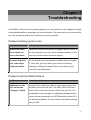
Troubleshooting
If the ADSL2+ Router is not functioning properly, you can refer first to this chapter for simple
troubleshooting before contacting your service provider. This could save your time and effort
but if the symptoms persist, then consult your service provider.
Problems starting up the router
Problem
Corrective Action
None of the LEDs
Check the connection between the adapter and the router. If
are on when you
the error persists, you may have a hardware problem. In this
turn on the router.
case you should contact technical support.
You have forgotten
Try the default login and password, please refers to Chapter
your router login
3. If this fails, you can restore your router to its factory
and/or password.
settings by holding the Reset button on the back of your
router for 6 seconds above.
Problems with the WAN Interface
Problem
Corrective Action
Initialization of the
Ensure that the telephone cable is connected properly from
PVC connection
the ADSL port to the wall jack. The ADSL LED on the front
(“linesync”) failed.
panel of the router should be on. Check that your VPI, VCI,
encapsulation type and type of multiplexing settings are the
same as those provided by your ISP. Reboot the router GE. If
you still have problems, you may need to verify these settings
with your ISP.
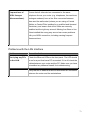
72
Frequent loss of
Ensure that all other devices connected to the same
ADSL linesync
telephone line as your router (e.g. telephones, fax machines,
(disconnections).
analogue modems) have a line filter connected between
them and the wall socket (unless you are using a Central
Splitter or Central Filter installed by a qualified and licensed
electrician), and ensure that all line filters are correctly
installed and the right way around. Missing line filters or line
filters installed the wrong way around can cause problems
with your ADSL connection, including causing frequent
disconnections.
Problems with the LAN Interface
Problem
Corrective Action
Can’t ping any PCs
Check the Ethernet LEDs on the front panel. The LED should
on the LAN.
be on for a port that has a PC connected. If it is off, check the
cables between your router and the PC. Make sure you have
uninstalled any software firewall for troubleshooting.
Verify that the IP address and the subnet mask are consistent
between the router and the workstations.
73
APPENDIX
Product Support and Contact Information
Most problems can be solved by referring to the Troubleshooting section in the User’s
Manual. If you cannot resolve the problem with the Troubleshooting chapter, please
contact the dealer where you purchased this product.
Contact Billion
WORLDWIDE
http://www.billion.com
74