1
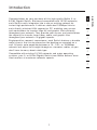
5-Port Gigabit Switch
8-Port Gigabit Switch
Belkin Tech Support
US: 877-736-5771
310-898-1100 ext. 2263
Europe: 00 800 223 55 460
Australia: 1800 235 546
New Zealand: 0800 235 546
Singapore: 800 616 1790
Belkin Corporation
501 West Walnut Street
Los Angeles, CA 90220-5221, USA
310-898-1100
310-898-1111 fax
Belkin Ltd.
7 Bowen Crescent, West Gosford
NSW 2250, Australia
+61 (0) 2 4372 8600
+61 (0) 2 4372 8603 fax
Belkin B.V.
Boeing Avenue 333
1119 PH Schiphol-Rijk, The Netherlands
+31 (0) 20 654 7300
+31 (0) 20 654 7349 fax
Belkin Ltd.
Express Business Park, Shipton Way
Rushden, NN10 6GL, United Kingdom
+44 (0) 1933 35 2000
+44 (0) 1933 31 2000 fax
© 2006 Belkin Corporation. All rights reserved. All trade names are registered trademarks of
respective manufacturers listed.
P75180
5-Port Gigabit Switch
8-Port Gigabit Switch
Share large files at faster network speeds,
with maximum efficiency
�������
�����
��
���������
�������
����� ����
����
�������
User Manual
�������
��
���������
F5D5141-5
F5D5141-8
�
�
���
Table of Contents
1 Introduction. . . . . . . . . . . . . . . . . . . . . . . . . . . . . . . . . . . . . . . . . . . . . . 1
Features . . . . . . . . . . . . . . . . . . . . . . . . . . . . . . . . . . . . . . . . . . . . . . 2
Package Contents . . . . . . . . . . . . . . . . . . . . . . . . . . . . . . . . . . . . . . 2
2 Getting to Know your Switch. . . . . . . . . . . . . . . . . . . . . . . . . . . . . . . . 3
3 Connecting Networking Devices to your Switch. . . . . . . . . . . . . . . . 4
4 Applications. . . . . . . . . . . . . . . . . . . . . . . . . . . . . . . . . . . . . . . . . . . . . . 7
5 Placement of the Switch . . . . . . . . . . . . . . . . . . . . . . . . . . . . . . . . . . . 8
6 Product Specifications . . . . . . . . . . . . . . . . . . . . . . . . . . . . . . . . . . . . . 9
7 Troubleshooting . . . . . . . . . . . . . . . . . . . . . . . . . . . . . . . . . . . . . . . . . 11
8 Information . . . . . . . . . . . . . . . . . . . . . . . . . . . . . . . . . . . . . . . . . . . . . 13
Introduction
Engineered for compact convenience, each Switch features a durable
metal chassis that can be placed on the desktop or mounted on a
wall. All ports auto-negotiate between a 10-, 100-, or 1000Mbps
network and adjust for straight-through or crossover cables, so you
don’t have to worry about cable type.
Compatible with existing 10/100 networks and major operating
systems, your 5- or 8-Port Gigabit Switch from Belkin delivers errorfree transfers at maximum networks speeds.
1
2
3
4
5
6
7
8
1
section
Congratulations on your purchase of this high-quality Belkin 5- or
8-Port Gigabit Switch. Backward-compatible with 10/100 networks,
each Switch easily integrates into a new or existing network for
instant high performance. It delivers dedicated 100Mbps links to
each directly attached LAN segment or PC, enabling your servers
and workstations to transfer large AV and graphic files efficiently
throughout your network. They provide your servers and workstations
the capacity to transfer large video, audio, and graphic files
throughout your network—at gigabit speeds.
Introduction
Features
-
High-speed, dedicated 10/100/1000 Ethernet ports
• 5 ports (Belkin 5-Port Gigabit Switch F5D5141-5)
• 8 ports (Belkin 8-Port Gigabit Switch F5D5141-8)
-
Standards
• IEEE 802.3 z/ab 1000Base-T
• IEEE 802.3u 100Base-Tx
• IEEE 802.3 10Base-T
-
1U chassis, place on your desk or mount on a wall
-
Auto MDI/MDIX ports
-
Auto-negotiation between 10-, 100-, and 1000Mbps on all ports
-
Auto-negotiation for full and half duplex on all ports
-
Collision detection on all ports
-
IEEE 802.3x PAUSE frames flow control in full-duplex operation
-
Back-pressure flow control in half-duplex operation
-
Support for up to 8,000 MAC address entries
-
A Belkin Limited Lifetime Warranty and free, 24-hour
technical support
Package Contents
•
Belkin 5- or 8-Port Gigabit Switch
•
Power Adapter
•
Self-Adhesive Rubber Pads for Desktop
•
User Manual
2
Getting to Know your Switch
1
Front-Panel LEDs
(b)
2
3
4
�
�
�
�
�
�
�
5
�
(c)
(a)
(a) Power (POWER) LED
•
Green – Switch is operating normally
•
Off – There is no power to the Switch
(b) Speed, Link, and Activity (Link/Act) LED
•
Solid Green – A valid link has been established
•
Blinking Green – Data is being transmitted and received
•
Off – No link is established
(c) 1000M LED
•
Solid Green – A valid 1000Mbps link is established
on the port
•
Off – A valid 10/100Mbps link is established on the port
3
6
7
8
section
Belkin 5- or 8-Port Gigabit Switches feature two rows of LEDs that
provide information about connection speed and activity, plus a
separate Power LED.
Connecting Networking Devices to your Switch
Connecting your Switch to your Computers
1.
Power down all your equipment.
2.
Connect a Category 5e or 6 Ethernet cable between each
computer’s network interface card (NIC) and one of the
numbered ports on the front of the Switch.
3.
All switch ports can automatically negotiate speeds at full- and
half-duplex modes to allow users to attach 10Base-T,
100Base-Tx, and 1000Base-T network devices.
4.
Connect the power adapter cord into the power adapter socket
in the rear of the Switch; now plug the adapter into a power
source (wall jack or power strip).
4
Connecting Networking Devices to your Switch
Connecting your Switch to your Broadband Router
1.
1
2
Note: If have questions regarding the configuration of your
broadband router setup, consult your broadband router vendor.
3
2.
Connect a Category 5e or 6 Ethernet cable between one of the
numbered ports on the rear of the broadband router and one of
the numbered ports on the rear of the Switch.
4
3.
Connect the power adapter cord into the power adapter socket
in the rear of the Switch; now plug the adapter into a power
source (wall jack or power strip).
4.
Power down all your computers.
5.
Connect a Category 5e or 6 Ethernet cable between each
computer’s NIC and one of the numbered ports on the rear
of the Switch.
6.
Power up all your computers connected to your Belkin Switch.
5
5
6
7
8
section
Make sure your broadband router is correctly configured to
connect to your ISP and you are able to surf the Internet.
Connecting Networking Devices to your Switch
Connecting your Switch to another Switch
1.
Connect a Category 5e or 6 cable between one of the numbered
ports on the front of the Switch and one of the numbered ports
on the other Switch to which you are cascading or connecting.
2.
All switch ports can automatically negotiate speeds at full- and
half-duplex modes to allow users to attach 10Base-T,
100Base-Tx, and 1000Base-T network switches or hubs.
3.
All ports support auto MDI and MDIX functionality. When
cascading or connecting switches or hubs, the user can use a
straight-through or crossover cable.
Important: When connecting two switches together, use a single
cable. If multiple cables are used, loops may occur resulting in
unwanted collisions. This will result in poor network performance.
Cabling Distances
•
328 ft. (100m)
Recommended Cabling Standard
•
Category 5e or 6 for gigabit connections (1000Mbps)
•
Category 5 for Ethernet (10Mbps) and Fast Ethernet
connections (100Mbps)
6
Applications
This Switch segments your network, significantly increasing both
bandwidth and throughput. Each port on the Switch can be attached
to any Ethernet, Fast Ethernet, or Gigabit Ethernet device, such as
another switch or a server’s network adapter. All Switch ports operate
at 10/00Mbps full and half duplex, or 1000Mbps full duplex, providing
up to 2Gbps of bandwidth to the attached device.
This Switch provides fully transparent bridging functions. It
automatically learns node addresses that are subsequently used to
filter and forward all traffic based on the destination address. When
traffic passes between devices attached to the same shared collision
domain, those packets are filtered from the Switch. But when traffic
must be passed between unique segments (i.e., different ports on the
Switch), the high-speed switching fabric forwards the packets at
near-zero latency.
2
3
4
5
6
7
Switching Functions –
Store-and-forward switching is used to forward traffic to other ports.
This scheme ensures data integrity and provides a clean data stream.
Sample Application –
This Switch is designed to operate as a small workgroup switch. It
can provide 10-, 100-, or 1000Mbps connections to workstations, or
1000Mbps full-duplex links to high-speed servers. It can also provide
a high-bandwidth uplink to the network backbone.
7
8
section
Bridging Functions –
1
Placement of the Switch
The Switches can be placed on a flat surface or on the wall.
Placement on a Flat Surface
1.
Affix the four rubber feet shipped with the Switch on the bottom
of the Switch in the area that is clearly marked on each of the
four corners.
2.
Make sure the Switch is placed in an area that allows for
proper ventilation.
3.
Place on a flat surface.
Placement on the Wall
1.
The wall-mount slots are two keyholes on the bottom of the
Switch. Attach two screws to the wall so that the Switch’s
wall-mount slots line up with the two screws.
2.
Place the Switch so that it rests on the two screws.
3.
Set the Switch on a flat surface in an open area to maximize
ventilation. Allow at least 2.5 inches on each side of the Switch
for proper ventilation and four inches at the back for proper
cable clearance.
4.
Make sure the power cable is close enough to reach a
power outlet.
8
Product Specifications
1
2
3
4
Physical Characteristics
IEEE Std 802.3-2002
Communication Rate
10/100/1000Mbps
Communication Mode
Full or half duplex at 10/100Mbps
Full duplex at 1000Mbps
Media Supported
10Base-T: 100-Ohm Category 3
or better twisted-pair
100Base-Tx: 100-Ohm Category 5
or better twisted-pair
1000Base-T: 100-Ohm Category 5,
5e, or 6 twisted-pair
Number of Ports
F5D5141-5: 5 RJ45 1000Base-T ports
F5D5141-8: 8 RJ45 1000Base-T ports
Indicator-Panel
Power
Link/Act, 1000Mbps
DC Input Power
F5D5141-5: 9V DC, 1A
F5D5141-8: 9V DC, 1A
Power Consumption
All 9W maximum
Temperature
Operating: 0 ~ 40˚ C (32 ~ 98˚ F)
Storage: -40 ~ 70˚ C (-40 ~ 158˚ F)
Humidity
10% to 90% non-condensing
Immunity
EN 61000-4-2/3/4/5/6/8/11
Emissions
FCC Class B, CISPR Class B,
EN 61000-3-2/3
Safety
CSA/CUS (CSA 60950-1 & UL 60950-1)
TÜV/GS (EN 60950-1) CB (IEC 60950-1)
Physical Dimensions
F5D5141-5:
(13 x 8.56 x
F5D5141-8:
(17.46 x 8.6
9
5.15 x 3.38 x 1.26 in.
3.19cm)
6.9 x 3.4 x 1.3 in.
x 3.29cm)
5
6
7
8
section
Standards Conformance
Product Specifications
Switching Criteria
Network Bridging Function
Filtering, forwarding, and learning
Switching Method
Store-and-forward
MAC Address Table
F5D5141-5: 8K entries
F5D5141-8: 8K entries
Packet Buffer
F5D5141-5: 80Kbits
F5D5141-8: 128Kbits
10
Troubleshooting
1
Diagnosing Switch Indicators
Symptom
Power LED does not light after power on.
Probable Causes
DC power adapter may be defective.
Possible Solutions
• Check for loose connections.
• Check the power outlet by using it for another device.
• Replace the DC power adapter.
2
3
4
5
6
Probable Causes
Switch port, network card, or cable may be defective.
7
Possible Solutions
• Check that the Switch and attached device are both
powered on.
• Be sure the network cable is connected to both devices.
• Verify that Category 5 or better cable is used for
10/100Mbps connections; Category 5, 5e, or 6 cable for
1000Mbps connections; and that the length of any cable
does not exceed 328 feet (100m).
• Check the network card and cable connections for defects.
• Replace the defective card or cable if necessary.
11
8
section
Symptom
Port (link) LED does not light after connection is made.
Troubleshooting
Power and Cooling Problems
If the power indicator does not turn on when the power cord
is plugged in, you may have a problem with the power outlet,
power cord, or internal power supply as explained in the
previous section. However, if the unit powers off after running
for a while, check for loose power connections, power losses
or surges at the power outlet, and verify that the fans on the
right side of the unit are unobstructed and running prior to
shutdown. If you still cannot isolate the problem, the internal
power supply may be defective.
Installation
Verify that all system components have been properly installed.
If one or more components (e.g., the power cord or network
cabling) appear to be malfunctioning, test them in an alternate
environment where you are sure that all the other components
are functioning properly.
You can find additional support information at
www.belkin.com/networking or www.belkin.com
through the tech-support area.
If you want to contact technical support by phone, please call
877-736-5771. Technical support is available 24 hours a day, 7
days a week.
Before you Call
If possible, turn on your system before you call Belkin for
technical assistance and call from a telephone at or near the
computer. You may be asked to describe detailed information
during operation.
12
Information
1
EMI Certification
FCC Class B Certification (USA)
Warning: This equipment generates, uses, and can radiate radio
frequency energy and, if not installed and used in accordance with the
instruction manual, may cause interference to radio communications.
It has been tested and found to comply with the limits for a Class
B digital device pursuant to Subpart B of Part 15 of FCC Rules,
which are designed to provide reasonable protection against such
interference when operated in a commercial environment. Operation
of this equipment in a residential area is likely to cause interference,
in which case the user, at his or her own expense, will be required to
take whatever measures are required to correct the interference. Use
unshielded twisted-pair (UTP) cabling for RJ45 connections; Category
3 cabling or greater for 10Mbps connections; Category 5 cabling
for 100Mbps connections; and Category 5, 5e, or 6 for 1000Mbps
connections.
CE Mark Declaration of Conformance for EMI and Safety (EEC)
This information technology equipment complies with the
requirements of the Council Directive 89/336/EEC on the
Approximation of the laws of the Member States relating to
Electromagnetic Compatibility and 73/23/EEC for electrical equipment
used within certain voltage limits and the Amendment Directive 93/68/
EEC. For the evaluation of the compliance with these Directives, the
following standards were applied:
RFI Emission:
• Limit class B according to EN 55022:1998
• Limit class A for harmonic current emission according to
EN 61000-3-2/1995
• Limitation of voltage fluctuation and flicker in low-voltage supply
system according to EN 61000-3-3/1995
13
3
4
5
6
7
8
section
Canada Department of Communications – Class B
This digital apparatus does not exceed the Class B limits for radio
noise emissions from digital apparatus as set out in the interferencecausing equipment standard entitled “Digital Apparatus,” ICES-003 of
the Department of Communications.
2
Information
Immunity:
• Product family standard according to EN 55024:1998
• Electrostatic Discharge according to EN 61000-4-2:1995
(Contact Discharge: ±4kV, Air Discharge: ±8kV)
• Radio-frequency electromagnetic field according to EN 61000-43:1996 (80–1000MHz with 1kHz AM 80% Modulation: 3V/m)
• Electrical fast transient/burst according to EN 61000-4-4:1995
(AC/DC power supply: ±1kV, data/signal lines: ±0.5kV)
• Surge immunity test according to EN 61000-4-5:1995 (AC/DC line
to line: ±1kV, AC/DC line to earth: ±2kV)
• Immunity to conducted disturbances, induced by radio-frequency
fields: EN 61000-4-6:1996 (0.15–80MHz with 1kHz AM 80%
modulation: 3V/m)
• Power frequency magnetic field immunity test according to EN
61000-4-8:1993 (1A/m at frequency 50Hz)
• Voltage dips, short interruptions, and voltage variations immunity
test according to EN 61000-4-11:1994 (>95% reduction @ 10ms,
30% reduction @ 500ms, >95% reduction @ 5000ms)
LVD:
• EN 60950-1
14
Information
Safety Compliance
Please read the following safety information carefully before installing
the Switch:
Warning: Do not plug a phone-jack connector into the RJ45 port. This
may damage this device.
1
2
Warning: This product does not contain any serviceable user parts.
3
Warning: When connecting this device to a power outlet, connect the
field ground lead on the tri-pole power plug to a valid earth ground
line to prevent electrical hazards.
4
Caution: Use only twisted-pair cables with RJ45 connectors that
conform to FCC standards.
5
This unit operates under SELV (Safety Extra Low Voltage) conditions
according to IEC 60950. The conditions are only maintained if
the equipment to which it is connected also operates under
SELV conditions.
6
7
15
section
8
Information
Belkin Corporation Limited Lifetime Product Warranty
What this warranty covers.
Belkin Corporation warrants to the original purchaser of this Belkin product
that the product shall be free of defects in design, assembly, material, or
workmanship.
What the period of coverage is.
Belkin Corporation warrants the Belkin product for the lifetime of the product.
What will we do to correct problems?
Product Warranty.
Belkin will repair or replace, at its option, any defective product free of
charge (except for shipping charges for the product).
What is not covered by this warranty?
All above warranties are null and void if the Belkin product is not provided to
Belkin Corporation for inspection upon Belkin’s request at the sole expense
of the purchaser, or if Belkin Corporation determines that the Belkin product
has been improperly installed, altered in any way, or tampered with. The
Belkin Product Warranty does not protect against acts of God (other than
lightning) such as flood, earthquake, war, vandalism, theft, normal-use wear
and tear, erosion, depletion, obsolescence, abuse, damage due to low
voltage disturbances (i.e. brownouts or sags), non-authorized program, or
system equipment modification or alteration.
How to get service.
To get service for your Belkin product you must take the following steps:
1. Contact Belkin Corporation at 501 W. Walnut St., Compton CA 90220,
Attn: Customer Service, or call (800)-223-5546, within 15 days of the
Occurrence. Be prepared to provide the following information:
a. The part number of the Belkin product.
b. Where you purchased the product.
c. When you purchased the product.
d. Copy of original receipt.
2. Your Belkin Customer Service Representative will then instruct you on
how to forward your receipt and Belkin product and how to proceed with
your claim.
16
Information
Belkin Corporation reserves the right to review the damaged Belkin product.
All costs of shipping the Belkin product to Belkin Corporation for inspection
shall be borne solely by the purchaser. If Belkin determines, in its sole
discretion, that it is impractical to ship the damaged equipment to Belkin
Corporation, Belkin may designate, in its sole discretion, an equipment repair
facility to inspect and estimate the cost to repair such equipment. The cost,
if any, of shipping the equipment to and from such repair facility and of such
estimate shall be borne solely by the purchaser. Damaged equipment must
remain available for inspection until the claim is finalized. Whenever claims
are settled, Belkin Corporation reserves the right to be subrogated under any
existing insurance policies the purchaser may have.
1
How state law relates to the warranty.
THIS WARRANTY CONTAINS THE SOLE WARRANTY OF BELKIN
CORPORATION, THERE ARE NO OTHER WARRANTIES, EXPRESSED
OR, EXCEPT AS REQUIRED BY LAW, IMPLIED, INCLUDING THE IMPLIED
WARRANTY OR CONDITION OF QUALITY, MERCHANTABILITY OR FITNESS
FOR A PARTICULAR PURPOSE, AND SUCH IMPLIED WARRANTIES, IF ANY,
ARE LIMITED IN DURATION TO THE TERM OF THIS WARRANTY.
5
IN NO EVENT SHALL BELKIN CORPORATION BE LIABLE FOR INCIDENTAL,
SPECIAL, DIRECT, INDIRECT, CONSEQUENTIAL OR MULTIPLE DAMAGES
SUCH AS, BUT NOT LIMITED TO, LOST BUSINESS OR PROFITS ARISING
OUT OF THE SALE OR USE OF ANY BELKIN PRODUCT, EVEN IF ADVISED
OF THE POSSIBILITY OF SUCH DAMAGES.
This warranty gives you specific legal rights, and you may also have other
rights, which may vary from state to state. Some states do not allow the
exclusion or limitation of incidental, consequential, or other damages, so the
above limitations may not apply to you.
17
3
4
6
7
8
section
Some states do not allow limitations on how long an implied warranty lasts,
so the above limitations may not apply to you.
2