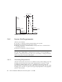
1
Sun Fire™ V1280/Netra™ 1280
Systems Site Planning Guide
Sun Microsystems, Inc.
www.sun.com
Part No. 817-3333-11
June 2006, Revision A
Submit comments about this document at: http://www.sun.com/hwdocs/feedback
Copyright 2006 Sun Microsystems, Inc., 4150 Network Circle, Santa Clara, California 95054, U.S.A. All rights reserved.
Sun Microsystems, Inc. has intellectual property rights relating to technology that is described in this document. In particular, and without
limitation, these intellectual property rights may include one or more of the U.S. patents listed at http://www.sun.com/patents and one or
more additional patents or pending patent applications in the U.S. and in other countries.
This document and the product to which it pertains are distributed under licenses restricting their use, copying, distribution, and
decompilation. No part of the product or of this document may be reproduced in any form by any means without prior written authorization of
Sun and its licensors, if any.
Third-party software, including font technology, is copyrighted and licensed from Sun suppliers.
Parts of the product may be derived from Berkeley BSD systems, licensed from the University of California. UNIX is a registered trademark in
the U.S. and in other countries, exclusively licensed through X/Open Company, Ltd.
Sun, Sun Microsystems, the Sun logo, AnswerBook2, docs.sun.com, Sun Fire, Sun StorEdge, Netra, and Solaris are trademarks or registered
trademarks of Sun Microsystems, Inc. in the U.S. and in other countries.
All SPARC trademarks are used under license and are trademarks or registered trademarks of SPARC International, Inc. in the U.S. and in other
countries. Products bearing SPARC trademarks are based upon an architecture developed by Sun Microsystems, Inc.
The OPEN LOOK and Sun™ Graphical User Interface was developed by Sun Microsystems, Inc. for its users and licensees. Sun acknowledges
the pioneering efforts of Xerox in researching and developing the concept of visual or graphical user interfaces for the computer industry. Sun
holds a non-exclusive license from Xerox to the Xerox Graphical User Interface, which license also covers Sun’s licensees who implement OPEN
LOOK GUIs and otherwise comply with Sun’s written license agreements.
U.S. Government Rights—Commercial use. Government users are subject to the Sun Microsystems, Inc. standard license agreement and
applicable provisions of the FAR and its supplements.
DOCUMENTATION IS PROVIDED "AS IS" AND ALL EXPRESS OR IMPLIED CONDITIONS, REPRESENTATIONS AND WARRANTIES,
INCLUDING ANY IMPLIED WARRANTY OF MERCHANTABILITY, FITNESS FOR A PARTICULAR PURPOSE OR NON-INFRINGEMENT,
ARE DISCLAIMED, EXCEPT TO THE EXTENT THAT SUCH DISCLAIMERS ARE HELD TO BE LEGALLY INVALID.
Copyright 2006 Sun Microsystems, Inc., 4150 Network Circle, Santa Clara, Californie 95054, Etats-Unis. Tous droits réservés.
Sun Microsystems, Inc. a les droits de propriété intellectuels relatants à la technologie qui est décrit dans ce document. En particulier, et sans la
limitation, ces droits de propriété intellectuels peuvent inclure un ou plus des brevets américains énumérés à http://www.sun.com/patents et
un ou les brevets plus supplémentaires ou les applications de brevet en attente dans les Etats-Unis et dans les autres pays.
Ce produit ou document est protégé par un copyright et distribué avec des licences qui en restreignent l’utilisation, la copie, la distribution, et la
décompilation. Aucune partie de ce produit ou document ne peut être reproduite sous aucune forme, par quelque moyen que ce soit, sans
l’autorisation préalable et écrite de Sun et de ses bailleurs de licence, s’il y en a.
Le logiciel détenu par des tiers, et qui comprend la technologie relative aux polices de caractères, est protégé par un copyright et licencié par des
fournisseurs de Sun.
Des parties de ce produit pourront être dérivées des systèmes Berkeley BSD licenciés par l’Université de Californie. UNIX est une marque
déposée aux Etats-Unis et dans d’autres pays et licenciée exclusivement par X/Open Company, Ltd.
Sun, Sun Microsystems, le logo Sun, AnswerBook2, docs.sun.com, Sun Fire, Sun StorEdge, Netra, et Solaris sont des marques de fabrique ou des
marques déposées de Sun Microsystems, Inc. aux Etats-Unis et dans d’autres pays.
Toutes les marques SPARC sont utilisées sous licence et sont des marques de fabrique ou des marques déposées de SPARC International, Inc.
aux Etats-Unis et dans d’autres pays. Les produits portant les marques SPARC sont basés sur une architecture développée par Sun
Microsystems, Inc.
L’interface d’utilisation graphique OPEN LOOK et Sun™ a été développée par Sun Microsystems, Inc. pour ses utilisateurs et licenciés. Sun
reconnaît les efforts de pionniers de Xerox pour la recherche et le développement du concept des interfaces d’utilisation visuelle ou graphique
pour l’industrie de l’informatique. Sun détient une license non exclusive de Xerox sur l’interface d’utilisation graphique Xerox, cette licence
couvrant également les licenciées de Sun qui mettent en place l’interface d ’utilisation graphique OPEN LOOK et qui en outre se conforment
aux licences écrites de Sun.
LA DOCUMENTATION EST FOURNIE "EN L’ÉTAT" ET TOUTES AUTRES CONDITIONS, DECLARATIONS ET GARANTIES EXPRESSES
OU TACITES SONT FORMELLEMENT EXCLUES, DANS LA MESURE AUTORISEE PAR LA LOI APPLICABLE, Y COMPRIS NOTAMMENT
TOUTE GARANTIE IMPLICITE RELATIVE A LA QUALITE MARCHANDE, A L’APTITUDE A UNE UTILISATION PARTICULIERE OU A
L’ABSENCE DE CONTREFAÇON.
Please
Recycle
Contents
Preface
1.
vii
Site Planning Checklist
1–1
1.1
1–1
System Packaging
1.1.1
1.2
2.
After Unpacking
Site Planning Checklist
1–2
1.2.1
Training
1–2
1.2.2
System Components
1.2.3
Physical Specifications
1.2.4
Environmental Requirements
1–2
1.2.5
Facility Power Requirements
1–2
Physical Specifications
1–2
1–2
2–1
2.1
Dimensions
2.2
Mounting Requirements
2.3
1–1
2–1
2.2.1
Vertical Space
2.2.2
Depth
2.2.3
Loading
2.2.4
Safety
2–5
Service Access
2–6
2–3
2–4
2–4
2–5
iii
2.4
3.
Seismic Applications
Environmental and Electrical Specifications
3.1
Environmental Requirements
3–1
3.1.1
Ambient Temperature
3–2
3.1.2
Ambient Relative Humidity
3–1
3–3
3.2
Airflow and Heat Dissipation
3.3
Sun Fire V1280 System Power Requirements
3.4
3–3
3–4
3.3.1
Grounding Requirements
3.3.2
Connecting AC Power for Redundancy
3–5
Netra 1280 System Power Requirements
3.4.1
3.4.2
iv
2–6
Source Site Requirements
3–6
3–6
3–8
3.4.1.1
Grounding Requirements
3.4.1.2
Overcurrent Protection Requirements
3.4.1.3
Disconnection and Isolation
3–9
Connecting DC Power for Redundancy
3–9
Sun Fire V1280/Netra 1280 Systems Site Planning Guide • June 2006
3–8
3–9
Tables
TABLE 2-1
System Dimensions
2–2
TABLE 3-1
Environmental Limits for Sun Fire V1280/Netra 1280 Systems
TABLE 3-2
Heat Dissipation
TABLE 3-4
Sun Fire V1280 System Power Requirements
TABLE 3-5
Sun Fire V1280 System Current and Power Consumption
TABLE 3-3
Sun Fire V1280 System AC Power Cord Ratings
TABLE 3-6
Netra 1280 System DC Feed Pair Ratings
TABLE 3-7
Netra 1280 System Current and Power Consumption
3–2
3–3
3–5
3–5
3–5
3–7
3–7
v
vi Sun Fire V1280/Netra 1280 Systems Site Planning Guide • June 2006
Preface
This guide describes the physical and environmental requirements for Sun Fire™
V1280/Netra™ 1280 systems.
How This Book Is Organized
Chapter 1 contains packing information and a site planning checklist.
Chapter 2 describes the physical requirements.
Chapter 3 describes the environmental requirements.
Related Documentation
TABLE P-1
Related Documentation
Application
Title
Safety
Sun Fire V1280/Netra 1280 Systems Compliance and Safety Manual
Use
Sun Fire V1280/Netra 1280 System Administration Guide
Use
Sun Fire V1280/Netra 1280 System Controller Command Reference Manual
Install
Sun Fire V1280/Netra 1280 Systems Installation Guide
Service
Sun Fire V1280/Netra 1280 Systems Service Manual
vii
Accessing Sun Documentation
You can view, print, or purchase a broad selection of Sun documentation, including
localized versions, at:
http://www.sun.com/documentation
Contacting Sun Technical Support
If you have technical questions about this product that are not answered in this
document, go to:
http://www.sun.com/service/contacting
Sun Welcomes Your Comments
Sun is interested in improving its documentation and welcomes your comments and
suggestions. You can submit your comments by going to:
http://www.sun.com/hwdocs/feedback
Please include the title and part number of your document with your feedback:
Sun Fire V1280/Netra 1280 Systems Site Planning Guide, part number 817-3333-11
viii Sun Fire V1280/Netra 1280 Systems Site Planning Guide • June 2006
Tools Required For Installation and
Service
The following tools are required for installation and service. They should be safely
stored and made readily available for service providers when required:
■
Installation tools:
■
■
■
■
■
■
■
■
■
Computer lifting device
Screwdriver, Phillips no. 2
13 mm wrench (spanner, supplied)
8 mm wrench (spanner, supplied)
Torque wrench and extension bar (Netra 1280 system only, supplied)
M5 nut spinner (Netra 1280 system only, supplied)
Crimp connectors 1-hole (Netra 1280 system only, supplied)
Crimp connectors 2-hole (Netra 1280 system only, supplied)
Service tools:
■
Screwdriver, Phillips no. 2
■
Needle nose pliers
■
ESD mat
■
ESD grounding wrist strap or foot strap
■
Compressor (Netra 1280 system)
■
Air hose (Netra 1280 system)
■
Safety platform
Preface
ix
x
Sun Fire V1280/Netra 1280 Systems Site Planning Guide • June 2006
CHAPTER
1
Site Planning Checklist
This chapter describes system requirements and the contents of the Sun Fire
V1280/Netra 1280 systems shipping package. The chapter contains the following
sections:
■
■
1.1
Section 1.1, “System Packaging” on page 1-1
Section 1.2, “Site Planning Checklist” on page 1-2
System Packaging
Sun Fire V1280/Netra 1280 systems are shipped secured to a wooden pallet by
brackets. The system is covered by shock-resistant packaging secured by a
corrugated cardboard cover, which itself is secured by unbreakable straps.
Graphics on the outside of the cover illustrate how to remove the cover and
associated packaging. No special tools are required.
The modules shipped within the system depend on the configuration ordered.
1.1.1
After Unpacking
The system weighs approximately 236 pounds (107 kg) when fully equipped. A
lifting device will be required to lift the system.
Ensure that doorways, corridors, and aisles are wide enough and high enough to
accommodate the system while it is being moved by the lifting device.
1-1
1.2
Site Planning Checklist
1.2.1
Training
■
1.2.2
System Components
■
■
1.2.3
■
■
■
■
Does the computer room environment meet the temperature and humidity
specifications (Section 3.2, “Airflow and Heat Dissipation” on page 3-3)?
Can the computer room environment specifications be maintained satisfactorily?
Is additional fire suppression equipment required?
Facility Power Requirements
■
■
■
■
1-2
Has the system location been established?
Does the equipment floor layout meet the equipment maintenance access
requirements (Section 2.3, “Service Access” on page 2-6)?
Is the equipment positioned so that the exhaust air of one device does not enter
the air inlet of another?
Environmental Requirements
■
1.2.5
Has the system configuration been determined?
What is the total number of systems?
Physical Specifications
■
1.2.4
Have system administrators and operators taken the necessary Sun Microsystems
training courses?
Have you determined system cabinet and peripheral cabinet(s) voltage?
Have sufficient power receptacles been ordered for each system, monitor, and
peripheral?
Are circuit breakers properly installed and labeled?
Are the power receptacles within 11.5 feet (3.5 meters) of the server cabinet
system, or within 6.0 feet (1.8 meters) of the standalone server system?
Sun Fire V1280/Netra 1280 Systems Site Planning Guide • June 2006
CHAPTER
2
Physical Specifications
This chapter describes the physical specifications and accessibility considerations for
Sun Fire V1280/Netra 1280 systems. It contains the following sections:
■
■
■
■
2.1
Section 2.1,
Section 2.2,
Section 2.3,
Section 2.4,
“Dimensions” on page 2-1
“Mounting Requirements” on page 2-3“
“Service Access” on page 2-6“
“Seismic Applications” on page 2-6”
Dimensions
The depth given on TABLE 2-1 does not include I/O connectors, power connectors, or
cable management features.
Cables are likely to protrude a minimum of 1.2 in. (3 cm) from the rear of the system,
and the telescopic slides protrude 1.1 in. (2.8 cm). The cable management arm could
add between 2.4 in. to 7.9 in. (6 cm to 20 cm) to the system depth.
Power connectors could add 2 in. (5 cm) to the depth.
2-1
TABLE 2-1 shows the shipping dimensions of a Sun Fire V1280/Netra 1280 system.
TABLE 2-1
System Dimensions
Measurement
Dimension
Width
Depth
Height
Weight
Misc.
2-2
Imperial
Metric
Including slides
17.50 in.
44.50 cm
Including mounting cradle
22.20 in.
56.48 cm
Including wooden pallet
23.62 in.
60.00 cm
System only
22.00 in.
55.80 cm
Including slides
22.40 in.
56.80 cm
Including mounting cradle
22.00 in.
55.82 cm
Including wooden pallet
27.76 in.
70.50 cm
12RU nominal
21.00 in.
53.34 cm
Including mounting cradle
25.30 in.
64.21 cm
Including wooden pallet
36.97 in.
93.90 cm
system only
236.0 lbs
107 kg
Including mounting cradle
286.0 lbs
130 kg
Including cable management and slides
310.0 lbs
141 kg
Opening in wooden pallet to
accommodate lifting device
(accepts standard cargo lifting devices)
24.60 in.
62.50 cm
Opening in orange mounting cradle to
accommodate lifting device
13.30 in.
33.70 cm
Sun Fire V1280/Netra 1280 Systems Site Planning Guide • June 2006
2.2
Mounting Requirements
Sun Fire V1280/Netra 1280 systems have been designed to accommodate the most
common mounting configurations. The rackmount kit that ships with the system
allows installation in the following racks:
■
Sun Rack 900 Cabinet
■
Sun Fire Cabinet
■
Sun StorEdgeTM Expansion Cabinet
■
19-inch IEC297/EIA310-D rack with a depth between mounting rails of 17.7
inches (45.00 cm) and 30.7 inches (78.00 cm).
■
19-inch two-post rack with a post depth of between 3 inches (7.62 cm) and
6 inches (15.24 cm).
An optional rackmount kit provides adapters to allow installation in a 23-inch twopost rack with a post depth of 5 inches (12.70 cm). These are intended for use with
Telco unequal flange seismic frames.
Sun Fire V1280/Netra 1280 systems must be mounted using screws suitable for the
equipment rack. The screws should be M5, M6, or no. 10-32 UNF (unified bolt
threads fine). All screws must be fitted. The recommended tightening torque value
for either M5 or no. 10-32 UNF recess head screws is 2.8 lb-f (3.8 N m), and that for
M6 screws is 4.4 lb-f (6 N m).
The vertical mounting hole pattern of the rack should conform to the standard
dimensions shown in FIGURE 2-1.
.5 in. (1.27 cm)
.62 in. (1.57 cm)
1RU
Centerline of slide
.62 in. (1.57 cm)
.5 in. (1.27 cm)
FIGURE 2-1
EIA/RETMA Universal Mounting Hole Pattern Dimensions
Ensure that the slides will fit the RETMA hole pattern so that the system, when
installed, aligns with a RU (rack unit) boundary.
Chapter 2
Physical Specifications
2-3
2.2.1
Vertical Space
Sun Fire V1280/Netra 1280 systems occupy 12 RU (21 in./53.34 cm) of vertical
height.
2.2.2
Depth
There must be a minimum of 22.44 inches (57.00 cm) usable internal depth in the
rack or cabinet.
Required usable depth (rack internal space) is dependant upon the cooling airflow
arrangement and the type of cable management used.
Examples of depth:
■
Minimum = 22.44 inches (57.00 cm)
The cable management arm (CMA) must not be installed, and the front cabinet
door must be removed (to provide maximum airflow) to achieve the minimum
depth (cable support must be provided by the installer).
■
Typical Lite = 25.3 inches (64.30 cm)
The CMA-lite cable management arm must be installed, and the front cabinet
door must be ventilated with 1 inch (2.50 cm) of air plenum to achieve the typical
lite depth.
■
Typical = 30.8 inches (78.30 cm)
The CMA-800 cable management arm must be installed, and the front cabinet
door must be ventilated with 1 inch (2.50 cm) of air plenum to achieve the typical
depth.
■
Maximum = 33.4 inches (84.80 cm)
The CMA-800 cable management arm must be installed, and the front cabinet
door must be solid with a 3.54 inch (9.00 cm) plenum at the front of the system to
act as a ventilation chimney. An inset to the front mounting rails of 4.5 inches.
(11.50 cm) is required.
2-4
Sun Fire V1280/Netra 1280 Systems Site Planning Guide • June 2006
2.2.3
Loading
The rack must be capable of supporting a static load of 236 pounds (107 kg) for each
fully configured Sun Fire V1280/Netra 1280 system installed. Dynamic load
considerations are subject to site location and application specifications.
In a suitably stable four-post rack, two Sun Fire V1280/Netra 1280 systems can be
fitted. Mounting hole information is provided in the Sun Fire V1280/Netra 1280
Systems Installation Guide.
No units or cables above or below a system should protrude beyond the front of the
system to ensure system access when the slides are extended.
Caution – Never mount multiple systems in a two-post rack.
2.2.4
Safety
Sun strongly suggests that all host cabinets containing a Sun Fire V1280/Netra 1280
system be anchored to the floor, to the ceiling, or to adjacent frames, using the
manufacturer’s instructions.
Free standing cabinets should be supplied with an anti-tilt feature, which must
sufficiently support the weight of the Sun Fire V1280/Netra 1280 system when
extended on its slides (usually a minimum of 10.6 inches (27 cm) from the front edge
of the rack). Where an anti-tilt feature is not supplied and the cabinet is not bolted to
the floor, a safety evaluation must be conducted by the installation or service
engineer to determine rack stability when the Sun Fire V1280/Netra 1280 system is
extended on its slides.
Prior to installing the cabinet on a raised floor, a safety evaluation must be
conducted by the installation or service engineer to ensure that the floor has
sufficient strength to handle the Sun Fire V1280/Netra 1280 system when extended
on its slides. In this case secure the rack through the raised floor to the concrete floor
below using a proprietary rack-mounting kit for the purpose.
Caution – When multiple systems are fitted in a cabinet, only one system can be
extended for service at any a time.
Chapter 2
Physical Specifications
2-5
2.3
Service Access
When determining the final location of the Sun Fire V1280/Netra 1280 system,
ensure there is enough space for service access. Allow a minimum of clearance of 35
inches (86.0 cm) at the front and rear of the system for service access.
The distance between cabinets can be zero. The last cabinet within any aisle should
be a minimum of 36 inches (91.4 cm) from any data center equipment or dividing
walls.
Note – Additional room on the right side of the system is desirable to improve
access for I/O and IB-SSC service.
2.4
Seismic Applications
If the Sun Fire V1280/Netra 1280 system is used in an environment where
Earthquake Zone 4 compliance is required, a rack designed to tolerate a Zone 4
earthquake must be selected, and independent tests undertaken to ensure system
compliance in these areas.
A seismic rack should be rigid enough to result in a fundamental resonance in the
horizontal axis of greater than 5 Hz with the Sun Fire V1280/Netra 1280 system
installed.
2-6
Sun Fire V1280/Netra 1280 Systems Site Planning Guide • June 2006
CHAPTER
3
Environmental and Electrical
Specifications
This chapter describes the environmental and electrical requirements for Sun Fire
V1280/Netra 1280 systems. It contains the following sections:
■
■
■
■
3.1
Section 3.1,
Section 3.2,
Section 3.3,
Section 3.4,
“Environmental Requirements” on page 3-1
“Airflow and Heat Dissipation” on page 3-3
“Sun Fire V1280 System Power Requirements” on page 3-4
“Netra 1280 System Power Requirements” on page 3-6
Environmental Requirements
The system can be installed in an environment with the specific operating ranges
shown in TABLE 3-1.
The design of your environmental control system—such as computer room airconditioning units—must ensure that intake air to the server system complies with
the limits specified in this section.
To avoid overheating:
■
■
Guard against directing any warm air toward the front of the cabinet.
Guard against directing warm air toward the system access panels.
TABLE 3-1 lists the environmental limits for Sun Fire V1280/Netra 1280 systems.
3-1
TABLE 3-1
Environmental Limits for Sun Fire V1280/Netra 1280 Systems
Environmental
Factor
Operating Range
Ambient
temperature*
41˚ to 95˚F (5˚ to 35˚C)
up to 550 yards (500 meters)d
–40˚ to 149˚F
(–40˚ to 65˚C*)
69.8˚ to 73.4˚F
(21˚ to 23˚C*)
Relative
humidity\
10 to 90% non condensing
80.6˚ (27˚C) maximum wet
bulb
10 to 90% nonconducting
100.4˚ (38˚C) maximum
wet bulb
45 to 50% non
condensing
Elevation
For UltraSPARC IV+ 1.8 GHz
CPU/Memory boards only,
maximum 7000 feet (2134
meters)
All other CPU/Memory
boards, maximum 10000 feet
(3048 meters)
maximum 39400’ feet
(12000 meters)
Non-Operating Range
Optimum
In addition to the above environmental conditions, the Netra 1280 complies with the
requirements of Telcordia SR-3580 (NEBS) Level 3.
* Does not apply to removable media devices.
\ Subject to a maximum absolute humidity of 0.024 kg of water per kg of dry air.
d Maximum ambient operating temperature is derated by 1 degree C per 500m elevation.
The operating environmental limits in TABLE 3-1 reflect systems testing. The optimum
condition is the suggested operating environment. Operating computer equipment
for extended periods at or near the temperature or humidity extremes is known to
significantly increase the failure rate of hardware components. It is strongly
suggested that customers plan and use the optimal temperature and humidity
ranges in order to minimize any chance of downtime due to component failure.
3.1.1
Ambient Temperature
The ambient temperature range of 69.8° to 73.4°F (21°C to 23°C) is optimal for
system reliability and operator comfort levels. Most computer equipment can
operate within a wide temperature range, but a level near 71.6°F (22°C) is desirable
because it is easier to maintain safe associated relative humidity levels at this
temperature. Operating in this temperature range provides a safety buffer in the
event the environmental support systems go down for a period of time. Though
individual standards vary slightly, 69.8° to 73.4°F (21°C to 23°C) should be used as
an optimal setting.
3-2
Sun Fire V1280/Netra 1280 Systems Site Planning Guide • June 2006
3.1.2
Ambient Relative Humidity
The ambient relative humidity levels between 45 percent and 50 percent are the most
suitable for safe data processing operations. Under certain circumstances, most data
processing equipment can operate within a fairly wide environmental range (20
percent to 80 percent), but the optimal goal should be between 45 percent to 50
percent for the following reasons:
■
■
■
Optimal range helps protect computer systems from corrosivity problems
associated with high humidity levels.
Optimal range provides the greatest operating time buffer in the event of
environmental control system failure.
This range helps avoid failures or temporary malfunctions caused by intermittent
interference from static discharges that might occur when relative humidity is too
low.
Electrostatic discharge (ESD) is easily generated and less easily dissipated in areas
where the relative humidity is below 35 percent. ESD becomes critical when levels
drop below 30 percent. The 5 percent relative humidity range might seem
unreasonably tight when compared to the guidelines used in typical office
environments or other loosely controlled areas; where as, it is not as difficult to
maintain in a data center because of the high efficiency vapor barrier and low rate of
air changes normally present.
3.2
Airflow and Heat Dissipation
The maximum rate of heat release from a Sun Fire V1280/Netra 1280 system with all
slots occupied and active is 3300 W (11300 British Thermal Units (BTU) per hour).
TABLE 3-2 shows detailed figures.
TABLE 3-2
Heat Dissipation
Configuration
Heat Dissipation
Sun Fire V1280
Netra 1280
4 CPUs, 8 Gbytes memory
1400W (4780 BTU/hr)
1500W (5120 BTU/hr)
8 CPUs, 16 Gbytes memory
2150W (7330 BTU/hr)
2310W (7880 BTU/hr)
12 CPUs, 24 Gbytes memory
2900W (9890 BTU/hr)
3120W (10640 BTU/hr)
12 CPUs, 96 Gbytes memory
3300W (11300 BTU/hr)
3530W (12030 BTU/hr)
Chapter 3
Environmental and Electrical Specifications
3-3
The Sun Fire V1280/Netra 1280 system has been designed to function while
mounted in a natural convection airflow. The following rules must be followed to
meet the environmental specification.
■
■
■
■
■
3.3
Ensure adequate airflow through the system. The Sun Fire V1280/Netra 1280
system uses internal fans that can achieve a total airflow of 400 cubic feet of air
per minute (cfm) in normal operating conditions.
The system has front-to-back cooling. The air inlet is at the front of the system.
The exhaust exits from the rear of the system.
Ventilation openings for both the inlet and exhaust of the system should provide
a minimum open area of 160 inches2 (1030 cm2) each.
Allow a minimum of clearance of 35 inches (86 cm) at the front and rear of the
system for adequate ventilation.
Ensure that additional equipment installed in the cabinet does not exceed
environmental limits at the air inlet. The environmental limits assume the system
is operating in the system cabinet with ventilated doors closed.
Sun Fire V1280 System Power
Requirements
The Sun Fire V1280 system is supplied ready for installation in an equipment rack.
Note – The voltage must be in the range 200–240 VAC for the system to power up.
The Sun Fire V1280 system is supplied with four detachable power cords fitted with
wall plugs to mate with the local electrical socket outlets. TABLE 3-3 shows the power
cord ratings.
Note – The plug at the end of each power cord is the primary means of
disconnection for this product.
3-4
Sun Fire V1280/Netra 1280 Systems Site Planning Guide • June 2006
TABLE 3-3
Sun Fire V1280 System AC Power Cord Ratings
Rating
Value
Voltage
200 to 240 VAC
Maximum input current per cord
9A at 200 VAC
Line cord
10A nominal
Circuit breakers – North America (4)
15A to 20A
Circuit breakers – international (4)
16A
TABLE 3-4 shows the on-site AC power requirements.
TABLE 3-4
Sun Fire V1280 System Power Requirements
Rating
Value
Voltage
200–240 VAC
Frequency
50–60 Hz
TABLE 3-5 shows the current and power consumption of the Sun Fire V1280 system at
200 VAC.
TABLE 3-5
3.3.1
Sun Fire V1280 System Current and Power Consumption
Rating
Value
Current
9A per cord, if only two cords are powered
Inrush Current
18A after 100µs
Surge Current
After 5ms brown-out short term surge is higher at 75A
Power Consumption
3300W max. total
Grounding Requirements
The Sun Fire V1280 system enclosure has an additional safety earth bonding point.
This bonding point must meet the central office requirements for enclosure or shelf
grounding in GR1089-CORE. This is for a path between the unit system and
enclosure metal or nearby point on the central office ground system.
The use of this bonding point connection is optional and is generally dependent on
the equipment practice of the installer.
Chapter 3
Environmental and Electrical Specifications
3-5
This bonding point is independent of the safety ground connection for the power
system grounding, which is provided by the earth wire present in each of the power
cords. This connection must be present.
3.3.2
Connecting AC Power for Redundancy
Caution – For optimum redundancy, the power cords should be connected to two
independent power sources (two power cords for each power source).
Most commonly, two independent power sources means an outside power line as
one source and an uninterrupted power supply backup system (UPS) as the second
source. That way, if a single power source should fail, the system will continue to
function.
Each power cable should have its own circuit breaker.
The system will not enter standby unless two system power supplies have in range
AC inputs.
3.4
Netra 1280 System Power Requirements
The Netra 1280 system is supplied ready for installation in an equipment rack.
Caution – This system has multiple power connections. You must open all
associated circuit breakers in order to completely remove power from the system.
Note – The voltage must be in the range –40 to –72 VDC for the system to power
on.
Caution – The power switch is not an On/Off switch. This power switch is an
On/Standby switch. It does not isolate the equipment. The circuit breakers are the
primary means for isolating the Netra 1280 system.
The power switch of the Netra 1280 system is a rocker style momentary action
switch. This switch controls only low voltage signals. No high voltage circuits pass
through this switch.
3-6
Sun Fire V1280/Netra 1280 Systems Site Planning Guide • June 2006
At least two dedicated power sources should be provided with positive-ground
circuit breakers, see Section 3.4.2, “Connecting DC Power for Redundancy” on
page 3-9 for details. Connector lugs are provided for crimping on to customersupplied cables.
The Netra 1280 system is supplied with connections for four feed pairs. TABLE 3-6
shows the feed-pair current ratings.
TABLE 3-6
Netra 1280 System DC Feed Pair Ratings
Rating
Value
Voltage
–40 to –72 VDC
Maximum input current per feed pair at –48 VDC
38A
Maximum input current per feed pair at –40 VDC
47A
Power supply wiring rating
47A
Circuit breaker panel
50A
Note – In North America, 90 degrees C 6 AWG copper conductors must be used.
Where other codes apply, 10 mm2 copper conductors must be used.
TABLE 3-7 shows the current and power consumption of the Netra 1280 system at –48
VDC.
Note – The circuit breakers are the primary means of disconnection for this product.
TABLE 3-7
Netra 1280 System Current and Power Consumption
Rating
Value
Current at –48 VDC
38A per feed pair, if only two feed pairs are powered*
Inrush Current
< 70A for < 100ms
Surge Current
After a brown-out of up to 75 ms, short term surge is < 150A for a
maximum of 4 ms, linearly decaying to the normal running current
in less than 10 ms (FIGURE 3-1).
Power Consumption
3530W maximum total split across two or more power feed pairs.
Less than 1900W for a single power supply feed pair.
* The worst case input current for each power supply is drawn when only two of the four power supplies have
supplied power. If the supply voltage is below –48V, then the current rises to a maximum of 47A.
Chapter 3
Environmental and Electrical Specifications
3-7
4 ms 10 ms
150A
Input
current
Full load
input current 50A
Full load
input current 50A
Dropout 0 ms
to 75 ms
FIGURE 3-1
3.4.1
Time
Surge Current
Source Site Requirements
The DC source must be:
■
■
■
■
–48 VDC or –60 VDC nominal centralized DC power system
Electrically isolated from any AC power source
Reliably connected to earth (the battery room positive bus is connected to the
grounding electrode)
Rated for a minimum of 50A per feed pair
Note – The Netra 1280 system must be installed in a restricted access location. The
IEC, EN and UL 60950 define a restricted access location as an area intended for
qualified or trained personnel only with access controlled by a locking mechanism
such as a key lock or an access card system.
3.4.1.1
Grounding Requirements
The Netra 1280 system enclosure has an additional safety earth bonding point. This
bonding point must meet the central office requirements for enclosure or shelf
grounding in GR1089-CORE. This is for a path between the unit system and
enclosure metal or nearby point on the central office ground system. The use of this
bonding point connection is optional and is generally dependent on the equipment
practice of the installer.
3-8
Sun Fire V1280/Netra 1280 Systems Site Planning Guide • June 2006
This is independent of the safety ground connection for the power system
grounding, which is provided by the two-hole connection on the DC inlet module.
3.4.1.2
Overcurrent Protection Requirements
Overcurrent protection devices must be provided as part of each host equipment
rack.
■ Four 50A single-pole, fast trip, DC-rated circuit breakers (one per ungrounded
supply conductor) must be located in the negative supply conductor between the
DC power source and the Netra 1280 system.
■ Circuit breakers must not trip when presented with inrush current of 60A lasting
200 ms.
Note – Overcurrent devices must meet applicable national and local electrical safety
codes and must be approved for the intended application.
3.4.1.3
Disconnection and Isolation
The disconnect devices for servicing are defined as the circuit breakers in all
negative supply conductors.
3.4.2
Connecting DC Power for Redundancy
Caution – For optimum redundancy, the feed pairs should be connected to two
independent power sources (two feed pairs to each power source).
Most commonly, two independent power sources means an outside power line as
one source and an uninterrupted power supply backup system (UPS) as the second
source. That way if a single power source should fail, the system will continue to
function.
Each power cable should have its own circuit breaker.
Chapter 3
Environmental and Electrical Specifications
3-9
3-10
Sun Fire V1280/Netra 1280 Systems Site Planning Guide • June 2006