1
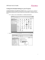
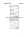
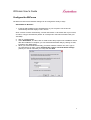
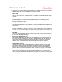
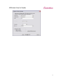
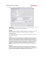
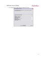
WiComm
Ethernet to Wireless Bridge Adapter
Installation and User’s Guide
WiComm User’s Guide
Notice
SystemBase Co.,Ltd. SPECIFICALLY DISCLAIMS THE IMPLIED WARRANTIES OF
MERCHANTABILITY AND FITNESS OF THIS PRODUCT FOR A PARTICULAR PURPOSE.
SystemBase shall not be liable for any errors contained in this manual or for any damages
resulting from loss of use, data, profits, or any incidental or consequential damages arising from
the use of SystemBase products or services. The information contained in this documentation is
subject to change without notice.
Information and descriptions contained herein are the property of SystemBase Co.,Ltd. Such
information and descriptions may not be copied, disseminated, or distributed without the express
written consent of SystemBase Co.,Ltd. This publication is subject to change without notice.
© Copyright 2007 SystemBase Co.,Ltd.
2
WiComm User’s Guide
Table of Contents
Introduction .................................................................................................................................4
Package Contents .......................................................................................................................4
™
Windows System Requirements ................................................................................................4
Other Operating Systems ............................................................................................................4
Wireless Requirements ...............................................................................................................5
WiComm Installation ...................................................................................................................5
Configure the Network Settings on your Computer ...................................................................6
Configure the WiComm............................................................................................................8
Web Browser Interface ..........................................................................................................15
Command Line Console Configuration ...................................................................................15
Connecting to your network enabled device...............................................................................16
Verifying Successful Installation ................................................................................................16
Troubleshooting ........................................................................................................................16
Push Button Function........................................................................................................... 177
LED Indicators ..................................................................................................................... 177
Where to Get Help................................................................................................................... 188
3
WiComm User’s Guide
Introduction
The WiComm Ethernet to Wireless Bridge Adapter allows you to easily add 802.11 b/g wireless
capabilities to any Ethernet product. It is ideal for connecting Ethernet enabled printers, scanners,
and multifunction printers (MFPs) to a wireless network without having to change drivers or
management utilities. The WiComm also brings 802.11 b/g wireless capabilities to Ethernet
enabled product such as desktop or laptop computers, point of sale terminals, medical devices,
and networked industrial control devices.
Once configured, the WiComm is platform independent so it will work with any operating system
and any network device. It provides Ethernet pass-through to the wireless network for network
features already provided by your Ethernet enabled device. The WiComm includes an RJ-45
connector for an auto-sensing 10/100 Ethernet, a reset button, a power connector, LEDs for
status indication, 802.11b/g WLAN connectivity, and a serial port for configuration or diagnostics.
Package Contents
•
WiComm Ethernet to Wireless Bridge Adapter
•
Power supply adapter
•
WiComm Documentation and Management Utilities CD
•
Crossover Ethernet Cable
Windows™ System Requirements
To configure the settings of the WiComm using the provided ExtendView Utility in Windows, your
Windows-based system should include the following components:
•
A PC with a 133 MHz or higher processor
•
Microsoft Windows 98SE, ME, 2000, XP, or 2003 server operating system
•
At least 64 MB of RAM (memory)
•
At least 10 MB of free hard disk space (to install the software)
•
A CD-ROM drive (to load the software)
•
An Internet connection (for online product registration)
Other Operating Systems
Users can access the configuration settings for the WiComm through a standard web browser by
entering the IP address of the WiComm into the address bar.
4
WiComm User’s Guide
Wireless Requirements
The WiComm allows you to connect to a wireless network consisting of either of the following:
• An 802.11b/g-compatible wireless-enabled PC connected directly to the WiComm
(Ad-Hoc or Peer-to-Peer Mode).
•
An 802.11b/g-compatible wireless access point that allows wireless and wired
Ethernet-enabled computers to connect to the serial server.
To configure the WiComm to communicate with your wireless network, you will need the following
information from your wireless network administrator:
•
Wireless Mode used (Infrastructure or Ad-Hoc)
•
The SSID (service set identifier) for your wireless network.
•
Wireless Security Settings (WEP/WPA keys, 802.1x settings, etc.)
WiComm Installation
Follow the steps below to install the WiComm.
Important: Before attempting to use the wireless connection with the WiComm, you must verify
that your Ethernet enabled device is able to connect directly with the wired LAN. If you can not
connect to the device on a wired LAN, you will not be able to connect to it and access it from the
wireless network. For details on configuring the networking functions of your Ethernet enabled
device, please see your device’s documentation.
1. Connect the WiComm to a computer’s RJ-45 Ethernet connection using the included
Ethernet cable. The WiComm Ethernet port supports MDIX (Automatic Crossover) so you
can use any crossover or standard Ethernet cable, but you will want to connect it directly
to the computer.
Important: Do not connect the WiComm to a hub or a switch. It is designed to
connect with one Ethernet address and could cause network loop-back issues if
connecting from a hub or switch to a wireless network.
2. Plug the WiComm power supply adapter into a suitable AC receptacle, and then plug the
power supply cable into the WiComm. The WiComm will run through a sequence of
power-up diagnostics for a few seconds.
3. Configure the WiComm to associate with your access point or wireless network.
Note: The WiComm will only allow configuration from one network interface at a time.
While both network interfaces (wired and wireless) are enabled to transmit and receive
raw packets, only one interface can be active for configuration (HTTP, Telnet or SNMP)
purposes at a time. The default interface is wired, but it can be changed to the wireless
interface by depressing the button on the back of the WiComm for less than 5 seconds or
in the software configuration using either ExtendView or the web browser interface.
5
WiComm User’s Guide
Configure the Network Settings on your Computer
The default IP Address of the WiComm is 169.254.111.111. You should set your computer to
automatically receive an IP Address so it will acquire an Auto-IP Address in order to be on the
same subnet as the WiComm to configure it. Below are the instructions for configuring a Windows
XP PC:
1. Click on Start, and then Control Panel. Go to Network Connections.
2. Right-Click on your Local Area Network connection and select Properties.
6
WiComm User’s Guide
3. Select Internet Protocol (TCP/IP) and click Properties.
4. On the General tab, select Obtain an IP address automatically and click OK, then OK
again.
7
WiComm User’s Guide
Configure the WiComm
The WiComm network and wireless settings can be configured a variety of ways.
ExtendView for Windows
1. Insert the CD supplied into the CD-ROM drive of your computer. The CD should
automatically start and display a menu screen.
Note: If it does not start automatically, click the Start button on the bottom left of your screen,
click Run, and type D:/Install.exe (where “D” corresponds to the letter associated with your
CD-ROM).
2. Click on Install Software.
3. Select ExtendView, and then click on Install. Follow the prompts in the installation wizard.
After the installation is complete, you can start the ExtendView utility by clicking on Start,
Programs, then ExtendView.
4. When you start the ExtendView utility, you will be asked to create a new view. Type in
any View Name you want. Check Automatically create a view with default settings
(unless you want to customize your view) and click Next.
8
WiComm User’s Guide
5. You should see the WiComm in the list. If you do not see the WiComm in the list, start
again and verify that all the steps were made correctly for the installation up to this point
again. Right-Click the WiComm (where the H/W address matches the one on the back
label of the WiComm) and click Configuration.
6. The IP Address settings of the WiComm are for configuration purposes only. These will
not effect the network device you are connecting to. You do not normally need to change
these settings if you want to continue to make future configuration changes by connecting
directly from a PC with a crossover Ethernet cable.
9
WiComm User’s Guide
7. Configure your wireless settings to match that of your wireless network. First choose the
Wireless Mode and type in the SSID of your wireless network.
Radio Mode
Radio mode allows you to select which wireless networks you want to connect to
(802.11b and/or 802.11g). Selecting 802.11b and g allows compatibility with both types of
networks.
Wireless Mode
For Wireless Mode, AD-HOC means the wireless network is composed of stations
without access points. INFRASTRUCTURE mode means all data is being passed
through a central access point.
SSID
The Service Set Identifier is used by stations to select the wireless network with which to
communicate.
RF Channel
Enter the desired 802.11 channel to be used on your network. Valid channel numbers are
1 through 11. The channel number only applies to AD_HOC mode. In Infrastructure, the
access point determines the channel used.
Data Rate
Select the desired maximum speed for communication. It is normally not recommended
to change the default speed setting.
International Roaming (802.11d)
This controls whether the radio frequencies are set based on the radio configuration, or
information from the access point it connects to. Disabled means the radio defaults are
used. Flexible means the access point settings are used if present, but if not the radio
default is used. Strict means the access point must provide regulatory frequency
information. It is normally not recommended to change the default.
Configuration Interface
The WiComm will only allow configuration from one network interface at a time. While
both network interfaces (wired and wireless) are enabled to transmit and receive raw
packets, only one interface can be active for configuration (HTTP, Telnet or SNMP)
purposes at a time. The default interface is wired, but it can be changed to the wireless
interface by selecting Wireless Connection.
Once you have entered the correct wireless mode and SSID for your wireless network,
click on Configure Wireless Security. The other settings on this page don’t normally need
to be changed.
10
WiComm User’s Guide
11
WiComm User’s Guide
8. Enter your wireless security settings to match that of your wireless network .
Key Selection
If WEP encryption is selected, and the authentication mode is not an EAP (802.1x) mode,
select the desired WEP key to be used, one through four.
WEP Key
These fields are ignored unless the encryption mode is 64 or 128 bit WEP. Enter up to 10
hexadecimal digits for 64 bit WEP, or 26 hexadecimal digits for 128 bit WEP.
Authentication Type
Choose type of authentication to be performed with the network access point, or with a
peer unit in Ad-hoc mode.
User ID
Enter the logon user ID that the WiComm uses to authenticate to the 802.1x enabled
network. The user ID and password must be in the authentication server database, and is
used in TTLS, LEAP, and PEAP configurations. The default user ID is 'anonymous'. A
realm defines a grouping of users. If a realm is required for your network, it is separated
from the user ID by a '@' character. Realms make it easier to segregate user groups into
independently administered databases, to apply policies on a user group basis, and to
establish roaming agreements to name a few applications. The default realm if not
specified is 'anonymous'. Realm is used with TTLS configurations, and sometimes with
PEAP.
Password
Enter the logon password that the server uses to authenticate to the 802.1x enabled
network. The user ID and password must be in the authentication server database, and is
used in TTLS, LEAP, and PEAP configurations. The password may be a text string, or a
string of hex bytes prefixed with '\x'. The default password is 'anonymous'.
12
WiComm User’s Guide
Certificate Common Name
Enter the name of the certificate on the primary authentication server. Up to two
Certificate Common Names are acceptable. If both of the common names are set to null,
all certificates are accepted. The default is null. Certificate common name is used in TLS,
TTLS and PEAP configurations.
Certificate Root Key
Enter the authentication key used to verify the root certificate in the certificate chain
provided by the authentication server. To set to null, leave this field blank. Certificate
Root Key is used in TLS, TTLS and PEAP configurations. The Certificate Root Key can
be extracted by clicking Browse and selecting the actual certificate if you don’t want to
type it in manually.
Certificate Root Key Exponent
This value must match the authentication server certificate value. The default is 65537
(x10001). Certificate Root Key Exponent is used in TLS, TTLS and PEAP configurations.
The Certificate Root Key Exponent can be extracted by clicking Browse and selecting the
actual certificate if you don’t want to type it in manually.
Authentication Protocol
This field determines how the server authenticates itself to the 802.1x enabled network
after an 802.1x session is established. The default is PAP. Sometimes referred to as
inner-authentication protocol, it is used in TTLS and PEAP configurations.
WPA-PSK
If the PSK mode of authentication is selected with WPA or WPA2 encryption, the key
value or pass-phrase entered here is used to initialize the session with the access point.
If a key value is entered, it must be exactly 64 hex characters. A pass-phrase must be 8
to 63 displayable characters.
13
WiComm User’s Guide
9. Click Finish after you have verified your settings are correct.
14
WiComm User’s Guide
Web Browser Interface
Open any web browser from your PC (eg: Internet Explorer or Firefox) and type the IP
Address of the WiComm for the Address (default is 169.254.111.111). Click Login from
the main menu in the left frame, and type in the password (default is ACCESS) and follow
these steps for configuration:
1. Click on Wireless from the main menu in the left frame.
2. Select Infrastructure or Ad-Hoc to match the Wireless mode and type in the
correct SSID.
3. Click Submit.
4. On the Configure Wireless screen, click on Configure Network Security. See
the ExtendView section above for details on the settings.
Command Line Console Configuration
The command line console can be access either using the serial port on the WiComm, or
by using Telnet.
Serial Port
1. Attach a null modem serial cable to the DB9 serial port of the WiComm, and the other
side to the COM port on your computer
2. Start a terminal emulation program, make sure you are connecting with the relevant
COM port. (Hyperterminal on Windows systems)
3. Use the following settings for the connection:
BITS PER SECOND:
115200
DATA BITS:
8
PARITY:
NONE
STOP BITS:
1
FLOW CONTROL:
NONE
This should connect you. Once connected, hit ENTER, you will be asked for a user name,
no user name is needed, so you can just hit ENTER. This will bring you to a Local>
prompt. This is where you can type your commands. Type HELP for a list of commands.
Telnet
Go to the command prompt on your PC and type TELNET ipaddress (where ipaddress
is the IP Address configured in the WiComm. You should get a # prompt, type in the
password (default is ACCESS, this will not echo on your screen as you type it). Hit
ENTER a couple times until you get a Local> prompt. This is where you can type your
commands. Type HELP to get a list of commands.
15
WiComm User’s Guide
Connecting to your network enabled device
Once you have configured the WiComm to communicate with your wireless network, you can
connect any Ethernet enabled device directly to the WiComm and it will communicate with
the wireless network.
1. Configure your Ethernet enabled device the same way you would for connecting it to
a wired LAN.
Important: Before attempting to use the wireless connection with the WiComm, you
must verify that your Ethernet enabled device is able to connect directly with the
wired LAN. If you can not connect to the device on a wired LAN, you will not be able
to connect to it and access it from the wireless network. For details on configuring the
networking functions of your Ethernet enabled device, please see your device’s
documentation.
2. Make sure the WiComm is configured to associate with your access point or wireless
network. Detailed configuration steps are provided in this document in the Configure
the WiComm section.
3. Connect your Ethernet enabled device directly to the WiComm with a network cable.
Important: Do not connect the WiComm to a hub or a switch. It is designed to
connect with one Ethernet address and could cause network loop-back issues if
connecting from a hub or switch to a wireless network.
Verifying Successful Installation
•
Verify that both the Ethernet device and the WiComm are powered on and ready, and
that a network cable is properly connected between them.
•
Check that the LEDs on the WiComm (refer to the LED chart on the next page) are
displaying a successful network and wireless link.
Troubleshooting
•
If you are having trouble accessing the connected network device, ensure you can
ping your Ethernet device using the DOS command PING ipaddress (where
ipaddress is the IP address of your network device connected to the WiComm). If
you cannot ping the device, you will not be able to access the device.
•
Verify that your access point is configured properly – note the settings, paying special
attention to the wireless mode, SSID or network name, and security settings so you
can configure the WiComm to the same wireless settings.
•
Make sure you have a good wireless signal from your PC and from the WiComm, that
they are within range (90 meters or 300 feet), and that they are away from metal
objects and other devices that generate radio signals (like Bluetooth devices,
cordless phones, and microwave ovens).
•
Make sure you are set to infrastructure mode if you are connecting through an
access point, or ad-hoc mode if you have a wireless network without an access point.
See the documentation for your wireless access point or PC card for details.
•
If you are experiencing slow performance or are having intermittent problems
connecting, try changing the RF channel of your wireless network. See your wireless
adapter and/or access point documentation for more information on configuration.
When changing the RF channel, it is recommended that you select a channel that is
at least three channels lower or higher than any other wireless networks within range.
•
You can reset the unit to factory default by holding in the button on the back of the
WiComm for more than 5 seconds and letting go.
16
WiComm User’s Guide
Push Button Function
Depressed for < 5 seconds
Toggle wired configuration mode – each time toggles
the network interface (wired or wireless) from which the
network configuration applications (ExtendView, HTTP
& TELNET) are accessible.
Reset configuration to factory defaults. The unit will reinitialize itself after updating the configuration memory.
Depressed for > 5 seconds
LED Indicators
FUNCTION
LED COLOR
STATE
STATUS
Status
Orange
Off
The device is receiving power
On
The device is not receiving power
Blinking
Error
Off
Off
No Wired Network Link
Wired network link is active, wireless
configuration is available
Wired network link is active, wired
Configuration is available
No Wireless Network Link
On
Wireless network link is active
Blinking
Wireless network data received
Network
Green
On
Blinking
Network
Yellow
17
WiComm User’s Guide
Where to Get Help
SystemBase offers several customer support options to assist you in the event you
experience difficulties with your product, including telephone support, repair services,
and warranty.
The worldwide web site provides a quick and easy way to answer many common
technical questions. It includes a wide variety of technical support tips, as well as copies
of product manuals, product literature, and firmware load images. The web site is
located at www.sysbas.com.
Your first point of contact for technical support is the Distributor or Dealer from whom
you bought your product. They are familiar with your needs, and will generally be able to
provide you with the fastest and most comprehensive support.
If your Distributor or Dealer is unable to answer your questions or is for some reason not
available, then contact SystemBase directly at (82) 2-855-0501. Or you can send an email to: [email protected] .
Before contacting Technical Support, please refer to the troubleshooting suggestions or
the web site in this manual to isolate any problems, and be sure to write down any error
messages. Also, make sure that you have the serial number of the product (located on
the product label on the card).
Returning Products
If you need to return a product for any reason (failures, incorrect shipments, etc.), follow
the steps below:
1. Contact the Technical Support group at (82) 2-855-0501 to request a Return Material
Authorization (RMA) number.
2. Be prepared with the serial number of the unit you are returning. You will be asked for the
serial number to verify warranty coverage.
Please record these serial numbers in the space provided below for future reference.
Model #: ________________________________
Server S/N: ____________________________________
18