1
Symetrix Inc.
14926 35th Avenue West
Lynnwood, Washington 98036
voice: (206) 787-3222
(800) 288-8855
fax: (206) 787-3211
Symetrix
602
Stereo Digital Processor
Owner’s Manual
Manual: Rev 1.1, 11/15/94
Software: Rev 2.03
Part number: 530602
Subject to change at our whim, and without notice.
Copyright (c) 1992-1994, Symetrix Inc. All rights reserved.
Batteries not included. Ground isn’t ground!
Available at finer studios everywhere.
No part of this manual may be reproduced or transmitted in any form or by any
means, electronic or mechanical, including photocopying, recording or by any
information storage and retrieval system, without permission, in writing, from
the publisher.
Production Information
This document was written using Microsoft Word for Windows V2.0 and 6.0. The drawings and graphs in
this manual were prepared using Corel Draw V2.0, Autocad V12, and Autoscript V5, then imported into
Word for Windows via encapsulated PostScript files. All page makeup occurred within Word for Windows.
Body text is set in Bookman 10pt and Section Heads are set in various sizes of Helvetica Bold. HelveticaNarrow was used for Figure and Table captions.
This manual was printed directly from PostScript files generated by Word for Windows on a Xerox
Docutech printer. This unique device is actually a laser printer, capable of 600 dpi resolution, with a
page throughput that rivals a high-speed photocopier. As a result, every page is a first-generation image.
Ain’t technology grand?
Table of Contents
1. Introduction ............................................................................................1-1
1.1 Manual Sections ..............................................................................................1-2
1.2 Operator Safety Summary ...............................................................................1-2
1.2.1 Equipment Markings .....................................................................................1-3
1.2.2 Terms............................................................................................................1-3
1.3 Other Safety Information..................................................................................1-4
2. Basics......................................................................................................2-1
2.1 What Does the 602 Do?...................................................................................2-1
2.2 Digital and Analog Differences .........................................................................2-1
2.3 Gain Setting .....................................................................................................2-1
2.4 Equalization .....................................................................................................2-2
2.4.1 Power and Fullness.......................................................................................2-2
2.4.2 Rhythm and Musical Foundation...................................................................2-2
2.4.3 Telephone Quality .........................................................................................2-3
2.4.4 Lisping Quality ..............................................................................................2-3
2.4.5 Presence Range ...........................................................................................2-3
2.4.6 Brilliance .......................................................................................................2-3
2.4.7 Conclusions ..................................................................................................2-4
2.4.8 Equalizing for Speech ...................................................................................2-4
2.4.9 Peaking or Shelving? ....................................................................................2-6
2.5 De-Essing ........................................................................................................2-6
2.6 Noise Reduction...............................................................................................2-7
2.7 Downward Expansion ......................................................................................2-7
2.8 Compression....................................................................................................2-7
2.9 AGC.................................................................................................................2-8
2.10 Delay..............................................................................................................2-9
2.11 Modulated Delay ............................................................................................2-9
2.12 MIDI ...............................................................................................................2-10
2.13 Program Memory ...........................................................................................2-10
3. Technical Tutorial ..................................................................................3-1
3.1 Matching Levels vs Matching Impedances.......................................................3-1
3.2 Signal Levels....................................................................................................3-2
3.3 I/O Impedances ...............................................................................................3-2
3.4 Polarity Convention ..........................................................................................3-3
3.5 Input and Output Connections .........................................................................3-3
3.6 Digital I/O Considerations ................................................................................3-5
3.7 MIDI I/O Considerations...................................................................................3-5
4. Front Panel Overview ............................................................................4-1
4.1 User Interface Summary ..................................................................................4-1
4.1.1 Loading Programs.........................................................................................4-1
4.1.2 Saving Programs ..........................................................................................4-1
4.1.3 Comparing Programs ....................................................................................4-2
4.2 Rate of Change Parameter ..............................................................................4-2
4.3 Input Level Control Block .................................................................................4-2
4.4 Parametric EQ Block........................................................................................4-3
4.4.1 EQ Band Select ............................................................................................4-3
4.4.2 EQ Parameter Group ....................................................................................4-4
4.5 Dynamics Processing Block .............................................................................4-4
4.5.1 Dynamic Noise Reduction Block ...................................................................4-4
4.5.2 De-Esser Block .............................................................................................4-5
i
4.5.3 Downward Expander Block ...........................................................................4-6
4.5.4 Compressor Parameter Block .......................................................................4-7
4.5.5 AGC Block ....................................................................................................4-7
4.5.6 Dynamics Section Control Summary.............................................................4-9
4.5.7 Additional Dynamics Parameters ..................................................................4-9
4.5.7.1 Sidechain filter ................................................................................4-10
4.5.7.2 Expander knee control....................................................................4-11
4.5.7.3 Compressor knee control................................................................4-11
4.5.7.4 AGC absolute threshold..................................................................4-11
4.5.7.5 AGC knee control ...........................................................................4-11
4.5.7.6 ARM peak release TC ....................................................................4-11
4.5.7.7 ARM integration TC ........................................................................4-11
4.5.7.8 ARM Signal/Noise threshold ...........................................................4-11
4.5.7.9 Log converter time constant ...........................................................4-11
4.5.7.10 Lookahead delay time...................................................................4-11
4.5.7.11 De-ess absolute threshold ............................................................4-12
4.6 Delay Group.....................................................................................................4-12
4.7 Output Group ...................................................................................................4-14
4.8 System Group..................................................................................................4-14
4.8.1 Global Switch ................................................................................................4-14
4.8.2 MIDI Switch...................................................................................................4-15
4.9 Presets Group..................................................................................................4-16
4.10 Setting Scenarios...........................................................................................4-17
4.11 Restoring Factory Presets..............................................................................4-19
4.12 Disabling the Front Panel ...............................................................................4-19
5. Rear Panel Overview..............................................................................5-1
6. Fast First Time Setup.............................................................................6-1
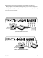
6.1 Connections .....................................................................................................6-1
6.2 Settings for Analog Sources.............................................................................6-2
6.3 Settings for Digital Sources..............................................................................6-4
7. Using the 602..........................................................................................7-1
7.1 Installation........................................................................................................7-1
7.2 Operational Details ..........................................................................................7-1
7.2.1 Stand-alone Operation ..................................................................................7-2
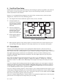
7.3 Block Diagrams................................................................................................7-4
7.3.1 Overall Block Diagram ..................................................................................7-4
7.3.2 Sequence of Processing ...............................................................................7-4
7.3.3 Dynamics Block ............................................................................................7-4
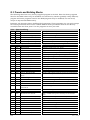
7.3.4 De-Ess and Noise Reduction Block...............................................................7-5
7.3.5 Delay Block ...................................................................................................7-6
7.4 System Interface ..............................................................................................7-6
7.4.1 Using the 602 as a Channel Insert Device ....................................................7-6
7.4.2 Using the 602 in a Send-Receive Loop .........................................................7-6
7.4.3 Using the 602 as an A-D Converter ..............................................................7-7
7.4.4 External Sample-Rate Clock .........................................................................7-7
7.4.5 Input/Output/Clock Summary ........................................................................7-7
7.4.6 MIDI Programming........................................................................................7-8
7.4.7 Accessing Parameters via MIDI ....................................................................7-8
7.4.8 Realtime MIDI ...............................................................................................7-8
7.4.9 Program Storage...........................................................................................7-8
7.4.10 Editing Parameters not Accessible from the Front Panel ............................7-9
7.5 Tips and Techniques for Using the 602............................................................7-10
7.5.1 Recalling and Storing Settings ......................................................................7-10
ii
7.5.2 Metering........................................................................................................7-10
7.5.3 Gain Setting ..................................................................................................7-11
7.5.4 Equalization ..................................................................................................7-11
7.5.5 Metering and the Dynamics Block.................................................................7-12
7.5.6 Dynamic Noise Reduction .............................................................................7-12
7.5.7 De-Esser.......................................................................................................7-12
7.5.8 Compression.................................................................................................7-13
7.5.9 AGC 7-13
7.5.10 Downward Expander...................................................................................7-13
7.5.11 Delay...........................................................................................................7-14
7.5.11.1 Echo effects..................................................................................7-14
7.5.11.2 Flanging........................................................................................7-14
7.5.11.3 Chorus effects ..............................................................................7-15
8. Applications............................................................................................8-1
8.1 Broadcast Voice Processing ............................................................................8-1
8.2 Voice-over Processing .....................................................................................8-1
8.3 Foley Processing .............................................................................................8-1
8.4 Digital Mastering ..............................................................................................8-1
8.5 Musical Applications.........................................................................................8-1
8.6 Sound Reinforcement Applications ..................................................................8-1
9. Troubleshooting Chart...........................................................................9-1
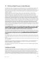
10. 602 Stereo Digital Processor Limited Warranty ................................10-1
11. Repair Information ...............................................................................11-1
11.1 Return Authorization ......................................................................................11-1
11.2 In-Warranty Repairs.......................................................................................11-1
11.3 Out-of-Warranty Repairs ................................................................................11-1
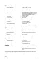
12. Specifications.......................................................................................12-1
A. Editing Realtime Midi Settings .............................................................A-1
A.1 Realtime MIDI Example. ..................................................................................A-2
B. Using the Lexicon MRC to Edit Realtime MIDI Settings .....................B-1
C. MIDI Implementation Notes...................................................................C-1
C.1 Overview .........................................................................................................C-1
C.1.1 Control Change (Bn).....................................................................................C-1
C.1.1.1 Example.........................................................................................C-1
C.1.2 Realtime MIDI...............................................................................................C-1
C.1.3 Sysex Implementation (F0)...........................................................................C-2
C.1.4 Sysex Echo ..................................................................................................C-3
C.1.5 Recognized MIDI Commands.......................................................................C-4
C.1.6 Data Structure Per Program .........................................................................C-8
C.1.7 MIDI Parameter Tables ................................................................................C-14
C.2 Hexadecimal Conversion Tables .....................................................................C-22
D. Glossary and Bibliography ...................................................................D-1
D.1 Glossary ..........................................................................................................D-1
D.2 Bibliography.....................................................................................................D-11
E. Architect’s and Engineer’s Specification ............................................E-1
iii
F. Disassembly Instructions......................................................................F-1
F.1 Top Cover Removal .........................................................................................F-1
F.2 Circuit Board Removal .....................................................................................F-1
F.2.1 Analog Board Removal .................................................................................F-1
F.2.2 Digital Board Removal ..................................................................................F-2
F.2.3 Power Supply Board Removal ......................................................................F-2
F.2.4 Front Panel Board Removal..........................................................................F-2
F.3 XLR Connector Removal (Important!!).............................................................F-2
G. Presets and Other Stuff ........................................................................G-1
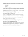
G.1 602 Programmer’s Worksheet.........................................................................G-2
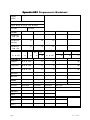
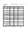
G.2 Midi Implementation Chart ..............................................................................G-3
G.3 Presets and Building Blocks ............................................................................G-4
iv
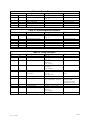
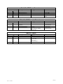
List of tables
TABLE 1. EDIT BUFFER DATA REQUEST ...................................................................................................... C-4
TABLE 2. EDIT BUFFER DATA RESPONSE .................................................................................................... C-4
TABLE 3. EDIT BUFFER DATA SET ............................................................................................................... C-4
TABLE 4. PROGRAM/SETUP DATA REQUEST ................................................................................................ C-5
TABLE 5. DATA RESPONSE ......................................................................................................................... C-5
TABLE 6. PROGRAM/SETUP DATA WRITE .................................................................................................... C-6
TABLE 7. IDENTIFY REQUEST ...................................................................................................................... C-6
TABLE 8. IDENTIFY RESPONSE .................................................................................................................... C-6
TABLE 9. PARAMETER MAP......................................................................................................................... C-7
TABLE 10. GLOBAL ..................................................................................................................................... C-8
TABLE 11. FILTER 1.................................................................................................................................... C-8
TABLE 12. FILTER 2.................................................................................................................................... C-8
TABLE 13. FILTER 3.................................................................................................................................... C-8
TABLE 14. DE-ESS PROCESSOR ................................................................................................................. C-9
TABLE 15. NOISE REDUCTION PROCESSOR ................................................................................................. C-9
TABLE 16. DELAY PROCESSOR ................................................................................................................... C-9
TABLE 17. EXPANSION PARAMETERS ........................................................................................................ C-10
TABLE 18. COMPRESSION PARAMETERS ................................................................................................... C-10
TABLE 19. AGC PARAMETERS.................................................................................................................. C-10
TABLE 20. ARM SENSE PARAMETERS ...................................................................................................... C-11
TABLE 21. LOG CONVERTER PARAMETERS .............................................................................................. C-11
TABLE 22. OUTPUT .................................................................................................................................. C-11
TABLE 23. REALTIME MIDI BLOCK 1 ......................................................................................................... C-12
TABLE 24. REALTIME MIDI BLOCK 2 ......................................................................................................... C-13
TABLE 25. MISCELLANEOUS...................................................................................................................... C-13
TABLE 26. ATTN18 TABLE (DB) ................................................................................................................ C-14
TABLE 27. ATTN82 TABLE (DB) ................................................................................................................ C-14
TABLE 28. ATTN100 TABLE (DB) .............................................................................................................. C-14
TABLE 29. PARAMETRIC BANDWIDTH TABLE (IN OCTAVES) ......................................................................... C-15
TABLE 30. FREQUENCY TABLE (HZ) .......................................................................................................... C-15
TABLE 31. OUTPUT LEVEL TABLE (DB)...................................................................................................... C-15
TABLE 32. EXPANDER RATIO TABLE .......................................................................................................... C-16
TABLE 33. COMPRESSOR RATIO TABLE..................................................................................................... C-16
TABLE 34. AGC RATIO TABLE .................................................................................................................. C-16
TABLE 35. ARM THRESHOLD (DB)............................................................................................................ C-17
TABLE 36. TIME CONSTANT TABLE............................................................................................................ C-17
TABLE 37. COMPRESSER/EXPANDER KNEE TABLE (IN DB): ........................................................................ C-17
TABLE 38. MAKEUP GAIN TABLE (ATTN24)................................................................................................ C-18
TABLE 39. SIDECHAIN LOOKAHEAD TIME (MS) TABLE ................................................................................. C-18
TABLE 40. DELAY TIME TABLE (MS) .......................................................................................................... C-18
TABLE 41. DELAY FEEDBACK TABLE: NEGATIVE THEN POSITIVE FEEDBACK (DB) ........................................ C-19
TABLE 42. DELAY LINE FILTER TABLE ....................................................................................................... C-19
TABLE 43. REALTIME SCALING TABLE ....................................................................................................... C-19
TABLE 44. DEFAULT PAN TABLE ............................................................................................................... C-20
TABLE 45. NORMALIZED MIDI PAN INPUT TABLE ....................................................................................... C-21
TABLE 46. HEX TO DECIMAL ..................................................................................................................... C-22
TABLE 47. DECIMAL TO HEX ..................................................................................................................... C-22
v
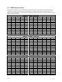
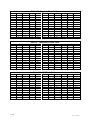
Alphabetical List of Tables
AGC PARAMETERS
AGC RATIO TABLE
ARM SENSE PARAMETERS
ARM THRESHOLD (DB)
ATTN100 TABLE(DB)
ATTN18 TABLE(DB)
ATTN82 TABLE(DB)
COMPRESSER/EXPANDER KNEE TABLE(IN DB):
COMPRESSION PARAMETERS
COMPRESSOR RATIO TABLE
DATA RESPONSE
DE-ESS PROCESSOR
DECIMAL TO HEX
DEFAULT PAN TABLE
DELAY FEEDBACK TABLE: NEGATIVE THEN POSITIVE FEEDBACK (DB)
DELAY LINE FILTER TABLE
DELAY PROCESSOR
DELAY TIME TABLE(MS)
EDIT BUFFER DATA REQUEST
EDIT BUFFER DATA RESPONSE
EDIT BUFFER DATA SET
EXPANDER RATIO TABLE
EXPANSION PARAMETERS
FILTER 1
FILTER 2
FILTER 3
FREQUENCY TABLE (HZ)
GLOBAL
HEX TO DECIMAL
IDENTIFY REQUEST
IDENTIFY RESPONSE
LOG CONVERTER PARAMETERS
MAKEUP GAIN TABLE (ATTN24)
MISCELLANEOUS
NOISE REDUCTION PROCESSOR
NORMALIZED MIDI PAN INPUT TABLE
OUTPUT
OUTPUT LEVEL TABLE (DB)
PARAMETER MAP
PARAMETRIC BANDWIDTH TABLE (IN OCTAVES)
PROGRAM/SETUP DATA REQUEST
PROGRAM/SETUP DATA WRITE
REALTIME MIDI BLOCK 1
REALTIME MIDI BLOCK 2
REALTIME SCALING TABLE
SIDECHAIN LOOKAHEAD TIME (MS) TABLE
TIME CONSTANT TABLE
vi
TABLE 19.
TABLE 34.
TABLE 20.
TABLE 35.
TABLE 28.
TABLE 26.
TABLE 27.
TABLE 37.
TABLE 18.
TABLE 33.
TABLE 5.
TABLE 14.
TABLE 47.
TABLE 44.
TABLE 41.
TABLE 42.
TABLE 16.
TABLE 40.
TABLE 1.
TABLE 2.
TABLE 3.
TABLE 32.
TABLE 17.
TABLE 11.
TABLE 12.
TABLE 13.
TABLE 30.
TABLE 10.
TABLE 46.
TABLE 7.
TABLE 8.
TABLE 21.
TABLE 38.
TABLE 25.
TABLE 15.
TABLE 45.
TABLE 22.
TABLE 31.
TABLE 9.
TABLE 29.
TABLE 4.
TABLE 6.
TABLE 23.
TABLE 24.
TABLE 43.
TABLE 39.
TABLE 36.
C-10
C-16
C-11
C-17
C-14
C-14
C-14
C-17
C-10
C-16
C-5
C-9
C-22
C-20
C-19
C-19
C-9
C-18
C-4
C-4
C-4
C-16
C-10
C-8
C-8
C-8
C-15
C-8
C-22
C-6
C-6
C-11
C-18
C-13
C-9
C-21
C-11
C-15
C-7
C-15
C-5
C-6
C-12
C-13
C-19
C-18
C-17
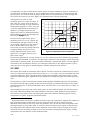
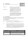
INPUT LEVEL CONTROL
BAND 1
BP
INPUT HEADROOM (dB)
54
48
42
36
30
24
18
12
BAND 2
BP
DIGITAL
IN/ SYNC
LOW
-18
+6
CH 1 / STEREO
1.
DYNAMICS PROCESSING
PARAMETRIC EQ
BAND 3
BP
FREQ(kHz)
COMPRESS
DS
DELAY
ATTACK(mS) RELEASE(mS)
MIX
DELAY(mS)
FEEDBACK
OUTPUT
SYSTEM
BYPASS
GLOBAL
PRESETS
SAVE
COMPARE
6 CLIP
-18
LEVEL(dB)
HIGH
WIDTH(Oct)
NR
42
OUTPUT HEADROOM (dB)
36 30 24 18 12 6 CLIP
-24 -20 -12 -9 -6 -4
GAIN REDUCTION (dB)
EXPANDER
AGC
FREQ(kHz) /
RATIO(X:1)
THRESH(dB)
FILTER
MODULATION
DEPTH
RATE
GAIN(dB) /
PAN
MIDI
LOAD
-2
LEAVE
EDIT
+6
CH 2
Introduction
The Symetrix 602 Stereo Digital Processor is a dual-channel digital signal processor intended
for use in a variety of recording, broadcast, live sound and post production applications. Acting
as a "bridge" between the analog and digital domains, the 602 accepts stereo line level analog
signals, converts them to 18-bit digital (44.1 kHz or 48 kHz sample rates), performs 24-bit
digital signal processing, and sends them on their way via the digital and analog outputs. The
602 uses two Motorola DSP-56001 digital signal processors (DSP) for an overall processing rate
of 40 million instructions per second (40 MIPS).
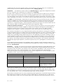
The 602 has inputs and outputs accommodating all common analog and digital formats. The
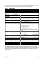
following table lists all of the inputs and outputs.
Input
Line (x2)
AES/EBU
S/PDIF
Mode
A
D
D
Output
Line (x2)
AES/EBU
S/PDIF
Mode
A
D
D
The stereo line inputs may be used in various combinations. The input and output modes are
separate; you can use almost any combination of the analog and digital outputs simultaneously
(for example, the AES/EBU and S/PDIF digital outputs cannot be used simultaneously).
While the 602 works great for voice (singing or monologue/dialogue) enhancement, its powerful
digital engine works wonders on any signal. Processing includes fully parametric EQ, shelving
EQ, notch filtering, dynamic noise filtering, de-essing, delay (first reflection), stereo synthesis,
gating, expansion, compression, and AGC (automatic gain control). Get the picture?
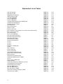
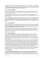
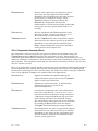
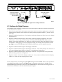
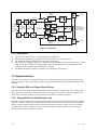
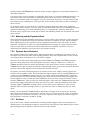
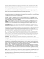
One aspect of many digital processors is the difficulty of use. The 602 was designed to be easy
to use, yet powerful. There are no menus to scroll through. Each parameter is visible via the
front panel push-switches. Pressing a switch transfers the display to that parameter's current
value. The parameter wheel allows you to change the value. Finally, the 602 allows you to
compare your stored setting with the current (edited) setting, without committing the edited
settings to memory.
Of course, all this processing power can be remotely controlled via MIDI. The 602's MIDI
implementation includes simple program change as well as parameter editing.
All analog inputs and outputs are available via XLR connectors. The AES/EBU digital inputs
and outputs use XLR connectors and the S/PDIF digital inputs and outputs use RCA
connectors. The MIDI input and output connections use standard 5-pin female DIN connectors.
The 602's unique set of digital tools can make voices, instruments, or sound effects jump out of
any mix.; Its combination of factory presets and non-volatile user program space guarantee
predictable and repeatable effects from session to session, performance to performance.
We recommend that you read this manual from cover to cover. Somewhere between the
confines of the two covers you should find the answers to most (98%) of your questions, both
technical as well as musical.
If you're in a hurry (like most of us), or if you really don't believe that someone could write a
decent owners manual that you can read and understand, then do us both a favor and read the
remainder of this section and Chapter 6, "Fast First Time Setup." Chapter 6 will help you get
Rev 1.1, 11/15/94
1-1
connected, tell you what the knobs do, and send you on your way. For MIDI information, go
directly to Appendix C, which describes some of the things that you can do with the 602 using
MIDI.
1.1 Manual Sections
This manual contains the following sections:
Chapter 1. Introduction introduces the 602 and this manual. Describes important safety
information
Chapter 2. Basics lets you know what the 602 does, and how it does it and some basic usage
information..
Chapter 3. Technical Tutorial a basic and not-so-basic discussion of signal levels, input and
output impedances, and connection polarity.
Chapter 4. Front Panel Overview gives a brief look at the controls and switches located on the
front panel of the 602.
Chapter 5. Rear Panel Overview gives a brief look at the rear panel of the 602.
Chapter 6. Fast, First Time Setup is a section written especially for people who just can't wait to
get their hands on the knobs.
Chapter 7. Using the 602 describes the use of the 602 in detail.
Chapter 8. Applications describes some of the myriad uses for the 602.
Chapter 9. Troubleshooting tells what to do if the 602 doesn't work.
Chapter 10. Limited Warranty describes the 602's warranty.
Chapter 11. Repair Information tells how to get your 602 repaired.
Chapter 12. Specifications lists the technical specifications of the 602's performance.
Appendix A. Appendix A describes how to use the realtime MIDI features built into the 602.
Appendix B. Appendix B tells how to use the Lexicon MRC with the 602.
Appendix C. Appendix C describes how to communicate with the 602 via MIDI. This appendix
also contains a description of the 602's Midi implementation.
Appendix D. Appendix D contains a glossary and a useful bibliography.
Appendix E. Appendix E contains the Architects and Engineer's specifications.
Appendix F. Appendix F contains disassembly instructions.
Appendix G. Appendix G contains a listing of the preset programs and other miscellany.
1.2 Operator Safety Summary
The information in this summary is intended for persons who operate the equipment as well as
repair personnel. Specific warnings and cautions are found throughout this manual wherever
they may apply; they do not appear in this summary.
1-2
Rev 1.1, 11/15/94
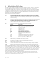
The notational conventions used in this manual and on the equipment itself are described in
the following paragraphs.
1.2.1 Equipment Markings
CAUTION
RISK OF ELECTRIC SHOCK
DO NOT OPEN
ATTENTION:
RISQUE DE CHOC ELECTRIQUE
NE PAS OUVRIR
No user serviceable parts inside. Refer servicing to qualified service personnel.
Il ne se trouve a l’interieur aucune piece pourvant entre reparée l’usager.
S’adresser a un reparateur compétent.
The lightning flash with arrowhead symbol
within an equilateral triangle is intended to
alert the user of the presence of uninsulated
"dangerous voltage" within the product's
enclosure that may be of sufficient
magnitude to constitute a risk of electric
shock to persons.
The exclamation point within an equilateral
triangle is intended to alert the user of the
presence of important operating and
maintenance (servicing) instructions in the
literature accompanying the appliance (i.e.
this manual).
Caution
To prevent electric shock, do not use the polarized plug supplied with this appliance with
any extension cord, receptacle, or other outlet unless the blades can be fully inserted to
prevent blade exposure.
1.2.2 Terms
Several notational conventions are used in this manual. Some paragraphs may use Note,
Caution, or Warning as a heading. These headings have the following meaning:
Convention
Description
Caution
Identifies information that, if not heeded, may cause
damage to the 602 or other equipment in your system.
Note
Identifies information that needs extra emphasis. A Note
generally supplies extra information to help you use the
602 better.
Warning
Identifies information that, if ignored, may be
hazardous to your health or that of others.
In addition, certain typefaces and capitalization are used to identify certain words. These
situations are:
Convention
Meaning
CAPITALS
Controls, switches or other markings on the chassis.
Boldface
Strong emphasis.
Helvetica-Narrow
Information appearing on the LED display
Rev 1.1, 11/15/94
1-3
Finally, two symbols are used as visual hints. They are:
Symbol
Meaning
N
Helping hand. A hint to make your life a bit easier.
M
The Bomb. A visual way of saying, “Caution!”
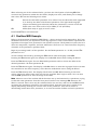
1.3 Other Safety Information
Power Source
This product is intended to operate from a power source
that does not apply more than 250V rms between the
power supply conductors or between either power
supply conductor and ground. A protective ground
connection, by way of the grounding conductor in the
power cord, is essential for safe operation
Grounding
The chassis of this product is grounded through the
grounding conductor of the power cord. To avoid electric
shock, plug the power cord into a properly wired
receptacle before making any connections to the
product. A protective ground connection, by way of the
grounding conductor in the power cord, is essential for
safe operation.
Danger from Loss of
Ground
If the protective ground connection is lost, all accessible
conductive parts, including knobs and controls that may
appear to be insulated, can render an electric shock.
Proper Power Cord
Use only the power cord and connector specified for the
product and your operating locale.
Use only a cord that is in good condition.
Proper Fuse
The fuse is mounted internally and is not considered
user serviceable. The fuseholder accepts American sized
fuses (1/4 in. dia.) or European sized fuses (5 mm dia).
For 117V ac operation, the correct value is 1/2A, 250V
ac, fast blowing (Bussman type AGC).
For 230V ac operation, the correct value is 1/4A, 250V
ac, slow blowing (Bussman type MDL or GDC) .
Operating Location
Do not operate this equipment under any of the
following conditions: explosive atmospheres, in wet
locations, in inclement weather, improper or unknown
AC mains voltage, or if improperly fused.
Stay Out of the Box
To avoid personal injury (or worse), do not remove the
product covers or panels. Do not operate the product
without the covers and panels properly installed.
User-serviceable parts
There are no user serviceable parts inside the 602. In
case of failure, refer all servicing to the factory. The
complexity of the DSP circuitry as well as the special
assembly tools required make the feasibility of field
service doubtful.
1-4
Rev 1.1, 11/15/94
2.
Basics
If the particular combination of processors in the 602 is strange or foreign to you, then we
suggest that you read and digest this section of the manual. If you should find some of the
terminology strange, you'll find a glossary of terms at the end of the manual. A very good
dictionary-style reference is also listed in the Bibliography.
2.1 What Does the 602 Do?
The 602 is a unique combination of four digital signal processors in one box: a versatile threeband parametric equalizer, a dynamic filter, a dynamics processor, and a digital delay. All of
these processors are implemented in the digital domain and the 602 can accept (or output)
signals in either the analog or digital domains.
One way to think about the particular combination of processors in the 602 is in terms of a
modern mixing console. Today, most mixing consoles have microphone and line inputs, some
sort of equalization, effects sends and returns, and (occasionally) on-board dynamics
processing. For a typical voice-over session, you would probably have a compressor/limiter and
a digital delay patched in as outboard processors. The 602 provides each of these processors
wrapped into one tidy one rack-space package.
2.2 Digital and Analog Differences
A large difference between the 602 and a mixing console is that the processing functions in the
602 are implemented totally within the digital domain whereas those within the console are
most likely implemented in the analog domain.
Outwardly there is no difference between an analog and a digital processor. A digital parametric
equalizer has the same controls that you're familiar with in the analog world. Granted, the way
that you access these controls may be different, but how much difference is there in seeing +9
dB on an LED display or in reading it off of a knob against a scale on the front panel?
2.3 Gain Setting
Wire is probably the only component of a sound system where we don't need to take signal
levels into account (usually). Any other active component of a sound system that passes signal
has a finite dynamic range. This means that our old friends dynamic range, headroom, and
noise floor are present and must be accounted for.
Tackling these terms in reverse order, noise floor represents the signal level of the device's
residual noise level. Realistically, this is somewhat lower than the lowest signal level that you'd
want to process (unless you want the output to sound noisy).
Headroom is the difference between the average signal level and peak clipping. Peak clipping
occurs because the processor can't increase its output to follow the signal. When this occurs,
the output signal simply flat-tops over the period that it can't follow its input (sort of like
clipping the tip of the peak off with a hedge-trimmer to level it off). Audibly speaking, clipping
and using the hedge-trimmer are about equivalent.
Dynamic range is the difference between the highest signal that may pass (limited by peak
clipping) and the lowest signal that will pass (limited by the noise floor). In a digital processor, a
0 dB signal may output a -120 dB noise floor but the smallest signal that may be represented
by 18-bits is a -108 dB square wave (because there is only one bit to toggle on and off).
Somewhere between these two points is the average level of your signal, as set by the
processor's level control. Set the average level too high and peak clipping will smash your peaks
flat, set it too low and suddenly the noise floor becomes audible (but you've got lots of
headroom!).
Rev 1.1, 11/15/94
2-1
The 602 allows you to set the signal levels in three different locations, which allows you to
make the best tradeoff between headroom and dynamic range. The analog inputs each have
gain controls to help you run these stages as hot as possible, without clipping. After conversion
to digital form, some signals may be too hot for any signal processing that results in an
increasing signal level. Thus, the 602 has a digital gain control that allows you to raise or lower
the level sent to the digital processors. Finally, there is an overall digital output gain control
allowing you to restore the signal level to "normal."
2.4 Equalization
Equalization is nothing more than selectively (or not) amplifying a signal based on frequency.
Since audio signals consist of combinations of fundamental signals and their harmonics,
changing the tonality or the spectral balance of a signal involves nothing more than altering the
relationship of the fundamental to its harmonics, and of the harmonics to themselves. Each
harmonic is responsible for one aspect of the audible character of a signal; knowing these
relationships allow you to quickly zero-in on the correct frequency range of the signal and
quickly apply boost or cut to enhance or correct what you are hearing.
The audio spectrum has several critical portions that are responsible for our perceptions of
sounds that we hear:1
Range
Frequencies
Musical Location
Very Low Bass
Bass
Midrange
Lisping Quality
Presence Range
Brilliance
16-64 Hz
64-256 Hz
256-2048 Hz
3000 Hz
4750-5000 Hz
6500-16 kHz
1st and 2nd octaves.
3rd and 4th octaves.
5th, 6th, and 7th octaves.
Between the 7th and 8th octaves.
Between the 8th and 9th octaves.
Part of the 9th through the 10th octave.
2.4.1 Power and Fullness.
In the very low bass region lies the threshold of feeling, where the lowest sounds, like wind, room
effects, and distant thunder, are felt, rather than heard. In the upper half of the first octave of
this range, research has shown that the fundamentals of piano, organ and even the harp reach
well into this range. Harvey Fletcher (of Fletcher-Munson fame) charted the sensitivity of the ear
for various parts of the spectrum at levels that are lower than those of reality. Fletcher's
compensation curves (the well known Fletcher-Munson curves) show that for equal loudness in
this range at lower recorded and reproduced levels shows requirements for tremendous boosts,
on the order of 10 to 30 dB. Aside from the subjective effects of this range, the ability to control
unwanted sounds in this range is equally important to subdue stage rumble and outside traffic
noise (especially important where there are subways beneath buildings!). Overemphasis caused
by close cardioid microphone placement can cause muddiness in the overall sound;
attenuating (cutting) the very-low-bass region can greatly improve overall clarity.
2.4.2 Rhythm and Musical Foundation.
In the bass region, most of the low, grave tones of the drum and piano can be found. Here we
can also find the fundamentals of the rhythm section, as well as the foundation of all musical
structure.
It was Leopold Stowkowski who said "If I had a thousand bass viols I could use them all!" This is not
as extreme as it may sound. A bass viol, even though it is reinforced by its sounding board,
generally plays single notes and possesses little dynamic range. In a large orchestra, as many as
1
The majority of the material in section 2.4 is taken from "Equalizing for Spectral
Character," Langevin Corporation, 1966 Catalog.
2-2
Rev 1.1, 11/15/94
eight bass viols may be used. A total of 1000 bass viols in this case would only give an additional
21 dB of level, which is not an inordinate amount given a glance at Mr. Fletcher's equal loudness
curves. Pay attention to this range because the overall musical balance of your program can be
controlled by equalizing or attenuating the 100 Hz range.
2.4.3 Telephone Quality
The ear is reasonably sensitive in the midrange frequencies, and sound restricted to this range
has a telephone-like quality (which is generally why telephone-quality frequency response
covers the 300-3 kHz range).
If you make the 6th octave (500-1024 Hz) louder with respect to the other octaves, the
subjective result is a horn-like quality. If you emphasize the 7th octave (1000-2000 Hz), the effect is
one of tinniness.
The fundamental tones in most music lie equally above and below middle C (261 Hz), from 128 to
512 Hz. As most instruments are rich in the first overtones, the majority of sound energy is found up
to the 2.5 kHz range. Music editors and others engaged in listening to music over long periods
find that listening fatigue can be reduced by attenuating the 5th, 6th, and 7th octaves by about
5 dB.
2.4.4 Lisping Quality
The 3 kHz range delivers a generous stimulus to the ear. At very loud levels the region of greatest
ear sensitivity shifts downward from 5 kHz; this is why many "PA" speakers have broad peaks in this
region. A characteristic of low-level signals peaked at 3 kHz is a "lisping" quality, and the total
inability to distinguish labial sounds such as m, b, and v.
In wide-range lower level systems, a peak in the 3 kHz region has a masking effect on important
recognition sounds, and on others which lie above 4 kHz. Brilliance and clarity are lost and
without attenuation of this region, an unconscious strain with increasing fatigue is felt according
to the amount of 3 kHz boost.
2.4.5 Presence Range
The usual band affecting clarity in male speech is 3000 to 6000 Hz. In a woman's voice, the
fundamentals are roughly an octave higher than a man's, and a woman's range of consonant
clarity lies between 5000 and 8000 Hz (the high-end of this range approaches a region of
hearing insensitivity in humans). Furthermore, the total range of a woman's voice is about half
that of a mans, stimulating fewer hearing nerves, and for this reason, is consequently still weaker
upon reception.
Wide range sounds, especially those of singing voices, have fundamentals with harmonics in the
5 kHz region of good ear sensitivity. Voices that are powerful or rich with harmonics at 5 kHz
sound especially pleasing, clear and full. Male opera singers are particularly favored with 5 kHz
sounds, women less so. In popular music, this range shifts downward somewhat. It follows that
voices deficient in the 5 kHz range can be enhanced in listening value by a generous boost on
the order of 5 to 8 dB at 5 kHz. A secondary benefit of this boost is an apparent increase in level;
a 6 dB rise at 5 kHz frequently gives an apparent increase of 3 dB to the overall signal.
Attenuating the 5 kHz range on instruments gives a "transparent" quality to the sound, providing,
of course, that the remainder of the signal is otherwise wide range. Microphones having a dip in
this region lack the "punch" or "presence" to which we (Americans) are accustomed.
2.4.6 Brilliance
Unvoiced consonants attributed to tooth, tongue and lip sounds are high in frequency, and
reach the 10 kHz range. These frequencies account for some clarity and most brilliance, even
though they contain less than 2% of the total speech energy. This also holds true for musical
instruments; especially percussion. Boosting or cutting this range affects clarity and naturalness.
Rev 1.1, 11/15/94
2-3
In speech, the 9th and 10th octaves impart intimacy although too much emphasis can make
secondary speech sounds (lip smacking, etc.) objectionable (a good case for a downward
expander).
Some microphones having a rise at the higher frequencies (especially omni microphones)
benefit from some attenuation in this region. Those microphones having underdamped
diaphragms may ring at these frequencies, causing an annoying sibilant distortion on speech.
On musical forms using hand percussion, boosting this range frequently results in an astonishing
and pleasing feeling of clarity.
2.4.7 Conclusions
When the article containing the above excerpts was written (probably around 1963), stereo was
just becoming a commercial reality (you could still purchase mono and stereo versions of an LP
and there were still more FM stations broadcasting in mono than stereo), and as many mixers
contained rotary mix pots as those that used slide pots. The value of individual channel
equalization was known, but it was both technologically and financially prohibitive. The article
concludes thusly:
"With the advent of stereo and three-channel recording, nearly three times the
equipment, with more elaboration, seems indicated, and expansion of console area in
the horizontal plane offers the only direction in which to proceed. But a single engineer
has arms only so long."
How times have changed!
2.4.8 Equalizing for Speech
In broadcast, equalizers are often used to create a sonic personality for the station's on-air
personalities. In the past, this has often meant using a single non-programmable equalizer in
the announce mic's signal chain. Considering the inverse rule of the knobs (the more knobs
you give them, the easier it is for someone to get hopelessly screwed up!), the attitude of most
station's PDs and engineers was to hide the equalizer somewhere, preferably under lock and
key. The 602makes it easy for each personality to have their own, individualized, curve.
Granted, if you give the jocks access to the unit, someone will inevitably shoot themselves in
the foot, but at least everyone can have their own curve.
Some general thoughts on speech equalization:
1.
2.
3.
4.
Try to use wider bandwidths. Narrower bandwidths (1/2 octave and less) are less audible
(harder to hear) and are generally only useful for remedial work. Broader bandwidths are
less obnoxious, more pleasing sounding, and easier to work with (especially if you're
boosting a range of frequencies).
Try to avoid massive amounts of boost or cut. If you're only trying to impart a flavor (like
sprinkling salt and pepper on a meal), then 6-8 dB of boost or cut should be all that you
need.
A wide bandwidth cut is equivalent to a boost at the frequencies surrounding the cut.
A quick way to figure out what's going on is to set the level of one band of the equalizer to
full boost (+18 dB), then switch to the frequency control and vary the frequency of that
band of the equalizer while listening to program material fed through the unit. This
usually makes quick work out of finding the region that you want to work on. Now reduce
the level setting to something tasteful.
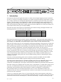
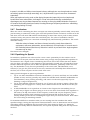
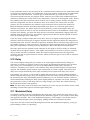
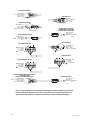
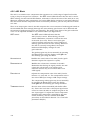
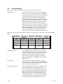
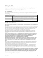
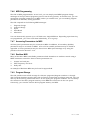
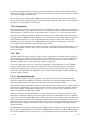
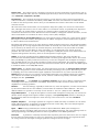
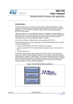
It’s sometimes difficult to translate what you are hearing into the numbers that make
equalizers happy. Seeing the frequencies associated with a voice or instrument can be helpful
in deciding where equalization may be needed. The chart shown in Figure 2-1 shows the
relationships of many different instruments, and a piano keyboard along with the frequencies
involved.
2-4
Rev 1.1, 11/15/94
BASS VIOL
BASS
ALTO
TENOR
CELLO
BARITONE
KETTLE DRUM
BASS TUBA
BASSOON
BASS CLARINET
TROMBONE
SOPRANO
VIOLA
FRENCH HORN
TRUMPET
CLARINET
VIOLIN
OBOE
FLUTE
PICCOLO
C0 D0 E0 F0 G0 A0 B0 C1 D1 E1 F1 G1 A1 B1 C2 D2 E2 F2 G2 A2 B2 C3 D3 E3 F3 G3 A3 B3 C4 D4 E4 F4 G4 A4 B4 C5 D5 E5 F5 G5 A5 B5 C6 D6 E6 F6 G6 A6 B6 C7 D7 E7 F7 G7 A7 B7 C8 D8 E8 F8 G8 A8 B8 C9 D9 E9 F9 G9 A9 B9
HUMAN
VOICE
STRING
INSTRUMENTS
WIND
INSTRUMENTS
TREBLE
Figure 2-1. Relationships of Musical instruments, Piano, and actual frequencies.
BASS
16.35
18.35
20.60
21.83
24.50
27.50
30.87
32.70
36.71
41.20
43.65
49.00
55.00
61.74
65.41
73.42
82.41
87.31
98.00
110.00
123.47
130.81
146.83
164.81
174.61
196.00
220.00
246.94
261.63
293.66
329.63
349.43
392.00
440.00
493.88
523.25
587.33
659.26
698.46
783.99
880.00
987.77
1046.50
1174.70
1318.50
1396.90
1568.00
1760.00
1975.50
2093.00
2349.30
2637.00
2793.80
3136.00
3520.00
3951.10
4186.00
4698.60
5274.00
5587.60
6272.00
7040.00
7902.20
8372.00
9393.20
10548.00
11175.20
12544.00
14080.00
15804.40
Rev 1.1, 11/15/94
2-5
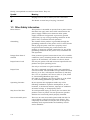
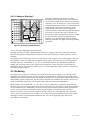
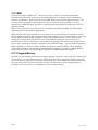
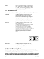
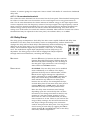
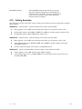
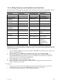
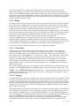
2.4.9 Peaking or Shelving?
Shelving
E.Q.
The 602s equalizer can operate in either
peaking or shelving mode. The two terms refer
to the overall shape of the equalizer's frequency
response curve. In Figure 2-3, you can see that
the peaking equalizer's effect is concentrated at
one frequency (the center frequency), with
progressively less effect above or below the
center frequency. The shelving equalizer (which
acts more or less like the tone controls on a
home stereo) affects frequencies above or below
its characteristic frequency (depending on
whether we're talking about a low-frequency
shelving equalizer or a high-frequency shelving
equalizer).
Peak/Dip
E.Q.
Rev-A
Figure 2-3. Shelving and peak/dip EQ curves.
At very narrow bandwidths (small number),
peaking equalizers exhibit a phenomenon known as "ringing." This quite aptly describes the
effect of the equalizer being sharply resonant at its center frequency, which makes it almost
oscillate.
In general, use the shelving curves to create overall color changes to the entire signal, and use
the peaking curves to modify specific regions of the signal. The peaking curves bring another
variable into play, "bandwidth" or "Q" as it is sometimes known. The bandwidth parameter
simply tells you how much of the region surrounding the center frequency will be affected.
Bandwidth and Q are inversely related; that is, a wide bandwidth (large number) corresponds
to a low Q (small number).
2.5 De-Essing
De-essing is the process of removing "S" sounds from speech or singing. The technique was
originally developed for motion picture dialogue recording when it was discovered that speech
sounded more natural when the accentuation of sibilants ("s" sounds) was reduced. By sensing
and limiting certain frequencies, the de-esser is intended to provide more specific control over
some of the higher frequency vocal sounds that tend to become overemphasized.
Most sibilant vocal sounds like "s", "sh," and "t" are very difficult to reproduce electronically
because they contain a large percentage of very high frequency harmonics. Since these sounds
are so essential to the intelligibility of speech, they can't be simply removed with equalization.
In fact, to help maintain articulation, many sound engineers routinely boost the higher
frequencies of the vocal spectrum (3 kHz to 8 kHz), and/or use microphones with "presence
curves" (like the Neumann U-87 or AKG C-414). However certain individuals and even certain
languages contain overemphasized sibilants and any sort of high frequency boost only
exacerbates the problem.
2-6
Rev 1.1, 11/15/94
2.6 Noise Reduction
Noise reduction is the process of removing the noise from a signal without (hopefully) affecting
the signal itself. There are two types of noise reduction: single ended (the 602), and doubleended (like Dolby noise reduction2).
A double-ended system such as the Dolby System eliminates noise contributed between its
encode and decode processors. By necessity, this means that you must have access to the
signal before it has noise added to it, and afterwards. For tape recorders and their ilk, this is
perfect. Of course, if you feed a Dolby noise-reduced system a noisy signal, it will simply hand
it back to you, without any added noise of course, but with just as much noise as you gave it to
begin with (garbage in, garbage out or GIGO).
A single ended noise reduction system works on whatever signal you hand it. Single-ended
systems depend on noise masking by the signal. That is, when the signal is present, it tends to
mask the noise. So when the signal is quiet or absent, reduce the noise (by reducing the highfrequency response), and when the signal is present, remove the high-frequency rolloff and
pray that the signal masks the noise.
If you're handed a noisy signal, then a single-ended noise reduction processor is your best
weapon against the noise. If you combine this with some careful equalization, you'll probably
end up with a signal that is more listenable.
2.7 Downward Expansion
Expansion is the process of increasing a signal's dynamic range, usually by increasing the
signal's level by a precise amount for every dB over a magic signal level (the "threshold").
Unfortunately, this requires infinite (or at least near infinite) headroom.
A simple, but entirely satisfactory solution is to reduce the signal's level for every dB below a
magic signal level (the "threshold"). This is called downward expansion. A similar and related
device is the signal gate. You can think of a signal gate as a special case of a downward
expander (or vice-versa if you must). Both devices reduce their output when their input signal
falls below threshold. The difference is the rate (not speed) at which they do it. The 602’s
downward expander output falls at an adjustable rate for every 1 dB below threshold of the
input signal. A gate's output falls by a nearly infinite amount for the slightest change, below
threshold, of the input signal. You can think of a gate as a downward expander taken to the
extreme, or you can think of a downward expander as a subtle example of a gate.
Gates are generally used to remove leakage (unwanted signals from nearby sources) from a
signal. Downward expanders are used to remove extraneous noise and to increase dynamic
range by making the softer parts softer.
Compressors or limiters (for the purposes of this discussion, a limiter is simply a high-ratio
compressor) are often used to reduce dynamic range by setting an upper limit on larger signals.
Sometimes, when you're trying to fit a signal through a transmission channel, it's better to put
processing to work on the lower end of the dynamic range than on the upper end. In other
words, instead of reducing the amount of change at the upper end of the dynamic range with a
compressor or limiter, try using a downward expander to increase the amount of change at the
lower end of the dynamic range.
2.8 Compression
Many times, a signal's dynamic range must be modified to allow it to pass through a
transmission channel without clipping or becoming noisy. Most often, audio engineers patch in
a compressor to restrict the dynamic range of a signal.
2
Dolby is a trademark of Dolby Laboratories, San Francisco, CA, USA.
Rev 1.1, 11/15/94
2-7
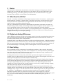
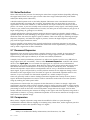
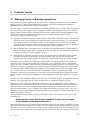
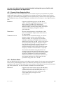
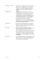
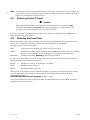
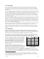
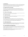
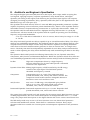
A compressor is a gain control device whose output is nearly constant in spite of variations in
its input level. A simple analogy is: you're holding the volume control for a sound system and
you're told to turn it down if the level gets louder than it is now and turn it down enough that
the level is the same as it is now. Figure 2-4 illustrates this concept graphically.
Compressors can also be used
creatively, that is to create an effect. In
this case, the "rules" such as they are,
go out of the window. A large amount of
compression applied to a voice-over can
create the impression of excitement or
intimacy, or simply help make the
signal very loud in a controlled manner,
which might be useful in ensuring that
the voice is always heard.
For most voice applications, pick a
moderate ratio (4:1 to 8:1), and set the
threshold low enough to achieve 6 dB
or so of gain reduction. Set the attack
time to retain some of the "edge" of
each word, and set the release time fast
enough to follow the speech. For a
heavily limited sound, set the ratio
higher (10:1 or higher) and use veryfast release times3.
Input (dBu) vs
STANDARD COMP/LIM GAIN CURVE
Output(dBu)
AUDIO PRECISION
50.000
40.000
3:1
Ratio
30.000
20.000
Threshold
Point
10.000
0.0
20:1
Ratio
Linear
1:1 Ratio
-10.00
-20.00
-30.00
-40.00
-40.0
-30.0
-20.0
-10.0
0
10.0
20.0
30.0
10.00
50.0
Figure 2-4. Input/Output curves of a compressor.
For musical applications, use low ratios (1.5:1 to 6:1) unless you want a deliberately squashed
sound. Set the threshold to achieve 4 to 6 dB of gain reduction. This setting is useful for subtly
controlling occasional peaks. To prevent peak overload of a subsequent device, use the highest
ratio and set the threshold to achieve 2 to 4 dB gain reduction on the highest peaks. If you’re
using the 602 to ride gain on mixed program, consider using the AGC section.
2.9 AGC
The letters AGC stand for Automatic Gain Control. An AGC can also be considered as a special
case of a compressor having a relatively low ratio (1:1 -> 4:1) and a very low threshold level and
a gated release time. Thus, any signal that exceeds the threshold causes some degree of gain
reduction. Additional gain, applied after the compressor, brings the signal level back up to line
level.
Functionally, an AGC works like an invisible (and hopefully inaudible) operator who monitors
the audio level and imperceptibly raises or lowers the gain to maintain the audio level at some
predetermined point. In its most simplistic form, that's all there is to it. (But there is a BUT, as
you will see.)
AGC amplifiers have been with us for many years. In the broadcast world, the old Gates LevelDevil and CBS Labs Audimax are both examples of old (circa 1960) products that performed
this function. The feature that sets these guys apart from common-ordinary-garden-variety
compressors is: gated, program-controlled release.
3
Fast attack times may become audible because of the time required to compute the amount of
gain reduction (analog compressors have the same problem, but they usually limit the
minimum attack time so you never have the problem). You can use the 602's compressor lookahead parameter to "buy some time" so that the initial overshoot of the signal is controlled by
the compressor. Fast release times cause problems of their own because changes in the gain
reduction may occur during a single cycle of the waveform, causing distortion. Again, analog
compressors are not immune to this problem either.
2-8
Rev 1.1, 11/15/94
If you remember back to the early days of TV, remember when someone at the network screwed
up and let the program lapse, the compressor at the local station would release and whoooosh,
up would come the noise floor...until the guy at network woke up, in which case it went
suuuuuuuck and back into the program audio. Both the Level-Devil and Audimax fixed this
problem by making the release time of the compressor a function of the program audio. That is,
they inhibited the gain reduction release if there was no audio present. If audio was present,
then the compressor was free to release as much as it wanted, but if there was no audio
present, the unit remained at the amount of gain reduction in force before the audio loss.
Both the Audimax and the Level-Devil depended upon silence to control the gain-release
function. In practice, the silence detector can be fooled by a noisy input signal. Since the
AGC/Leveler needs to work at very low threshold levels in order to accommodate a wide range
of input levels (ideally, you want the AGC/Leveler to function with signals ranging from near
thermal noise to high line level), an ordinary signal-present detector would respond to hum or
noise by mistaking it for a valid signal.
If you try using a simple compressor as an AGC, there is no signal-controlled gated-release
function. Thus the overall gain is highest anytime that the signal falls below the compressor's
threshold. By itself, this isn't disastrous (perfectly workable with a noiseless input signal), but
the sudden change in noise level when a normal-level signal presents itself is a dead giveaway
that your compressor is lacking in the IQ department. This is the BUT mentioned earlier.
The 602's AGC function performs some analysis on the signal in order to make an informed
decision about the signal's nature. If the signal is determined to be noise or silence, then the
AGC's release function is inhibited. When the signal analyzer detects that the signal has
returned, the AGC is again allowed to release, which causes the gain to rise or fall in response
to the signal level.
2.10 Delay
One of the simplest things that you can do to an audio signal to dramatically change its
character is to add in a delayed version of the signal. By adjusting parameters such as delay
time, delay level, and feedback, you can create impressions of time, space, distance or
reflection. The delay in the 602 is a two-channel delay with paralleled inputs and separated
outputs. The feedback paths between input and output are cross-coupled. This means that
delay one's output feeds delay two's input and delay two's output feeds delay one's input.
For example, you can get a '50s sound by adding 250 ms delay to a signal. Adding feedback
makes the delay effect linger, since the feedback causes the echoes to repeat until they die out.
By shortening the delay and fiddling with the feedback, you can simulate reflective rooms of
various dimensions. Making the delay times slightly different "spreads" the sound, eliminating
the point-source effect. If the delay times are long enough, you'll hear the echoes bouncing
back and forth between the speakers.
Note: the dual-delay used in the 602 is not sufficient to create any sort of realistic reverb. Good
sounding reverberation requires a multi-tapped delay line.
2.11 Modulated Delay
Yet another wrinkle on delay is modulating the delay time. This causes the delay time to vary
according to the frequency and amplitude of the modulating signal. If you choose a short delay
time (typically around 1 ms), a low modulation frequency, and roughly a 50-50 mix of direct
signal and delayed signal, you'll get flanging. Adding feedback accentuates the effect.
If you alter the mix to favor the delayed signal and raise the modulation frequency, you'll get
pitch bending, vibrato, or chorusing.
Rev 1.1, 11/15/94
2-9
2.12 MIDI
If you aren't aware of MIDI, well... Several years ago, a number of musical synthesizer
manufacturers somehow agreed on a serial data protocol to exchange control information
between synthesizers. They called the result MIDI: Musical Instrument Digital Interface. The
success of this standard is phenomenal (not that it is perfect) and the ability to control
something via MIDI has been applied to everything from synthesizers to signal processors to
lighting systems.
Nearly every parameter of the 602 may be controlled or modified via MIDI. The 602's MIDI
implementation is described in Appendix C.
What does this mean for the 602? At a very basic level, it means that you could have several
setups stored in the 602 and change between them remotely. If you're a broadcaster, you could
have a MIDI controller output program change commands based on a clock, which would
change the settings of the on-air 602 to the personalized settings for each of your on-air
personalities. If you're a musician, it means that the settings of the 602 can be changed from
note to note, measure to measure, during the solo, between songs, ...get the picture? The 602's
MIDI capability can also be used for dynamic parameter control (realtime control via MIDI
continuous controller) and parameter editing (making parameter changes via MIDI). Both of
these activities require an external MIDI controller or a MIDI-equipped computer.
2.13 Program Memory
The 602 has 256 memory locations for program storage. The first 128 locations are reserved for
user memory; the last 128 locations are reserved for the factory supplied programs. You may
recall any factory program (or any other stored program), edit it (modify any of its parameters),
and store the result into one of the user memory locations. Later, these programs may be
recalled via the front panel, or via MIDI for reuse or further editing.
2-10
Rev 1.1, 11/15/94
3.
Technical Tutorial
This section discusses a multitude of things, all related to getting signals in and out of the 602.
3.1 Matching Levels vs Matching Impedances
In any audio equipment application, the question of "matching" inevitably comes up. Without
digging a hole any deeper than absolutely necessary, we offer the following discussion to
(hopefully) clarify your understanding of the subject.
Over the years, we have all had impedance matching pounded into our heads. This is important
only for ancient audio systems, power amplifiers, and RF. Technically speaking, the reason is
power transfer, which reaches a maximum when source and load are matched. Modern audio
systems are voltage transmission systems and source and load matching is not only
unnecessary, but undesirable as well.
❒
Ancient audio systems operate at 600 ohms (or some other impedance value), and must be
matched, both at their inputs and at their outputs. Generally speaking, if you are dealing
with equipment that uses vacuum tubes, or was designed prior to 1970, you should be
concerned about matching. These units were designed when audio systems were based on
maximum power transfer, hence the need for input/output matching.
❒
Power amplifiers are fussy because an abnormally low load impedance generally means a
visit to the amp hospital. Thus, it's important to know what the total impedance of the pile
of speakers connected to the amplifier really is.
❒
RF systems are matched because we really are concerned with maximum power transfer
and with matching the impedance of the transmission line (keeps nasty things from
happening). Video signals (composite, baseband, or otherwise) should be treated like RF.
Some folks seem to believe that balanced/unbalanced lines and impedances are related; or
even worse that they are associated with a particular type of connector. Not so. Unbalanced
signals are not necessarily high-impedance and balanced signals/lines are not necessarily lowimpedance. Similarly, although 1/4 inch jacks are typically used for things like guitars (which
are high-impedance and unbalanced), this does not predispose them to only this usage. After
all, 1/4 inch jacks are sometimes used for loudspeakers, which are anything but highimpedance. Therefore, the presence of 3-pin XLR connectors should not be construed to mean
that the input or output is low-impedance (or high-impedance). The same applies to 1/4 inch
jacks.
So, what is really important? Signal level, and (to a much lesser degree), the impedance relation
between an output (signal source) and the input that it connects to (signal receiver).
Signal level is very important. Mismatch causes either loss of headroom or loss of signal-tonoise ratio. Thus, microphone inputs should only see signals originating from a microphone, a
direct (DI) box, or an output designated microphone-level output. Electrically, this is in the
range of approximately -70 to -20 dBm. Line inputs should only see signals in the -10 to +24
dBm/dBu range. Guitars, high-impedance microphones, and many electronic keyboards do not
qualify as line-level sources.
The impedance relation between outputs and inputs needs to be considered, but only in the
following way:
Always make sure that a device's input impedance is higher than the output
source impedance of the device that drives it.
Some manufacturers state a relatively high-impedance figure as the output impedance of their
equipment. What they really mean is that this is the minimum load impedance that they would
like their gear to see. In most cases, seeing a output impedance figure of 10,000 (10K) ohms or
higher from modern equipment that requires power (batteries or AC) is an instance of this type
Rev 1.1, 11/15/94
3-1
of rating. If so, then the input impedance of the succeeding input must be equal to or greater
than the output impedance of the driving device.
Symetrix equipment inputs are designed to bridge (be greater than 10 times the actual source
impedance) the output of whatever device drives the input. Symetrix equipment outputs are
designed to drive 600-ohm or higher loads (600-ohm loads are an archaic practice that won't go
away). You don't need to terminate the output with a 600-ohm resistor if you aren't driving a
600-ohm load. If you don't understand the concept of termination, you probably don't need to
anyway.
The two facts that you need to derive from this discussion are:
1.
Match signal levels for best headroom and signal-to-noise ratio.
2.
For audio, impedance matching is only needed for antique equipment and power amplifier
outputs. In all other cases, ensure that your inputs bridge (are in the range of 2 to 200
times the output source impedance) your outputs.
3.2 Signal Levels
The 602 is designed around studio/professional line levels: +4 dBu or 1.23 volts. The unit is
quiet enough to operate at lower signal levels such as those found in semi-pro or
musical-instrument (MI) equipment (-10 dBu or 300 millivolts).
3.3 I/O Impedances
The 602 is designed to interface into almost any recording studio or sound reinforcement
application. This includes:
❒
600-ohm systems where input and output impedances are matched.
❒
Unbalanced semi-professional equipment applications.
❒
Modern bridging systems where inputs bridge and outputs are low source impedances
(voltage transmission systems).
The 602's input impedance is 12.5 kΩ balanced, and 9.4 kΩ unbalanced. The inputs may be
driven from any source (balanced or unbalanced) capable of delivering at least -10 dBu into the
aforementioned impedances.
The 602's output impedance is 300-ohms balanced, 150-ohms unbalanced. The output line
driver delivers +21.5 dBm into 600-ohm balanced loads or +15.5 dBm into 600-ohm
unbalanced loads.
3-2
Rev 1.1, 11/15/94
3.4 Polarity Convention
The 602 uses the international standard polarity convention of pin 2 hot. Therefore:
XLR
Tip-RingSleeve
Signal
1
2
3
Sleeve
Tip
Ring
Ground
High
Low
If your system uses balanced inputs and
outputs, and uses the 602 this way, then the
polarity convention is unimportant. If your
system is both balanced and unbalanced, then
you must pay attention to this, especially when
going in and coming out through different
connector types (like input on an XLR, output
on a phone jack).
3.5 Input and Output Connections
Figure 3-1 illustrates how to connect the 602 to balanced and unbalanced analog sources and
analog loads.
To operate the 602 from unbalanced sources, run a 2-conductor shielded cable (that's two
conductors plus the shield) from the source to the 602. At the source, connect the low/minus
side to the shield, these connect to the source's ground; connect the high/plus side to the
source's signal connection. At the 602, the high/plus wire connects to pin 2, the low/minus
wire connects to pin 3, and the shield (always) connects to pin 1. This is the preferred method
as it makes best use of the 602's balanced input (even though the source is unbalanced). The
other alternative shown in Figure 3-1 converts the 602's balanced input into an unbalanced
input at the input connector. This works, but is more susceptible to hum and buzz than the
preferred method. There is no level difference between either method.
You can drive unbalanced loads with the 602's outputs by using the XLR connector with pin 3
left open. In an emergency (the show must go on), you can ground pin 3, but if you have the
choice...leave it open. If you must ground pin 3, it is must be grounded at the 602, rather than
at the other end of the cable. The price, regardless of whether or not pin 3 is grounded is 6 dB
less output level. This can be easily made up via the output gain controls. If your system is
wired with pin 3 hot, pin 2 must float if you are driving an unbalanced load.
Rev 1.1, 11/15/94
3-3
FROM BALANCED OUT
2 31
TO BALANCED IN
231
FEMALE XLR
PIN 1 = GROUND
PIN 2 = HIGH
PIN 3 = LOW
MALE XLR
PIN 1 = GROUND
PIN 2 = HIGH
PIN 3 = LOW
FROM BALANCED OUT
TIP
MALE TRS PLUG
TIP = HIGH
RING = LOW
SLEEVE = GROUND
RING
SLEEVE
TO UNBALANCED IN FROM
TRANSFORMER COUPLED OR
FLOATING BALANCED OUTPUT
MALE TS PLUG
TIP = HIGH
SLEEVE = GROUND +
LOW
FROM UNBALANCED OUT
MALE TS PLUG
TIP = HIGH
SLEEVE = GROUND +
LOW
TO BALANCED IN
FROM BALANCED OUT
TERMINAL STRIP
(+) = HIGH
(-) = LOW
= GROUND
TIP
RING
MALE TRS PLUG
TIP = HIGH
RING = LOW
SLEEVE = GROUND
SLEEVE
TO BALANCED IN
FROM UNBALANCED OUT
TERMINAL STRIP
(+) = HIGH
(-) = NOT USED
= GROUND
FROM NON-TRANSFORMER (ELECTRONIC)
BALANCED OUTPUT
(TYPICAL OF SYMETRIX PRODUCTS)
-
2 31
FEMALE XLR
PIN 1 = GROUND + LOW
PIN 2 = HIGH
PIN 3 = NOT USED
TERMINAL STRIP
(+) = HIGH
(-) = LOW
= GROUND
TO UNBALANCED IN
MALE TS PLUG
TIP = HIGH
SLEEVE = GROUND +
LOW
REV-B
Figure 3-1. Input and output connector wiring. These diagrams represent the majority of connectors
used in modern audio equipment. Locate the source connector in the left column and match it up
with the destination connector in the right column. Wire your cable according to the diagrams
3-4
Rev 1.1, 11/15/94
3.6 Digital I/O Considerations
The 602 has two similar, but different, digital input/output formats: AES/EBU and S/PDIF.
The AES/EBU format uses XLR connectors, is balanced, and operates at 110 ohms line
impedance. The S/PDIF (Sony-Phillips Digital InterFace) format uses RCA connectors, is
unbalanced, and operates at 75 ohms line impedance. The digital input and output is
transformer coupled for freedom from ground loops.
3.7
MIDI I/O Considerations
The 602 has two MIDI connections: MIDI in and MIDI out. There is no MIDI thru connection.
Both connectors follow the standard defined by the IMA (International MIDI Association).
The MIDI out jack echoes the MIDI input, minus any sysex messages aimed at the 602 that
owns the MIDI connectors. All other messages are echoed. There is a small throughput delay
that may become significant if many 602s are wired in cascade (series).
Rev 1.1, 11/15/94
3-5
Notes
3-6
Rev 1.1, 11/15/94
4. Front Panel Overview
INPUT LEVEL CONTROL
BAND 1
BP
INPUT HEADROOM (dB)
54
48
42
36
30
24
18
12
BAND 2
BP
DIGITAL
IN/ SYNC
LOW
-18
+6
CH 1 / STEREO
DYNAMICS PROCESSING
PARAMETRIC EQ
BAND 3
BP
FREQ(kHz)
DS
COMPRESS
DELAY
ATTACK(mS) RELEASE(mS)
MIX
DELAY(mS)
FEEDBACK
OUTPUT
SYSTEM
BYPASS
GLOBAL
PRESETS
SAVE
COMPARE
6 CLIP
-18
LEVEL(dB)
HIGH
WIDTH(Oct)
NR
42
OUTPUT HEADROOM (dB)
36 30 24 18 12 6 CLIP
-24 -20 -12 -9 -6 -4
GAIN REDUCTION (dB)
EXPANDER
AGC
FREQ(kHz) /
RATIO(X:1)
THRESH(dB)
FILTER
MODULATION
DEPTH
RATE
GAIN(dB) /
PAN
MIDI
-2
LEAVE
EDIT
LOAD
+6
CH 2
4.1 User Interface Summary
The user interface of the 602 has been designed to be powerful yet intuitive. Most switches
have only one function and where a switch has several functions, the display prompts for the
parameter in question. There are no hierarchical menus.
The parameter adjustment wheel (Wheel) modifies the
parameter or function selected via the front panel
switches. The Wheel is sensitive to direction, and velocity.
Thus, turning the Wheel quickly causes the display to
change very quickly, and turning the Wheel slowly causes
the display to change very slowly (as if there were a gear
reduction unit on the Wheel).
42
OUTPUT HEADROOM (dB)
36 30 24 18 12 6 CLIP
-24 -20 -12 -9 -6 -4
GAIN REDUCTION (dB)
-2
Select a function for editing by pressing its associated switch once. The switch begins flashing.
Next, select the parameter that you want to edit and press its switch. The display indicates the
current value. Turning the Wheel changes the value.
If a function switch has several choices, the display indicates the choice, and the Wheel cycles
through the options. An example of this sort of function switch is the GLOBAL switch.
4.1.1
Loading Programs
A program is nothing more than a group of control settings. To load (recall) a
program, press the LEAVE EDIT switch to return to the top-most control level.
The display now indicates the current program number. Rotate the Wheel
until the desired program number appears flashing in the display. Press the
LOAD switch. When the program has loaded, the display says donE and the
number stops flashing.
N
SYSTEM
LOBAL
PRESETS
SAVE
24
COMPARE
-24
MIDI
LOAD
LEAVE
EDIT
Note: the 602 always loads a copy of the program stored in program memory
into the edit buffer. The contents of the edit buffer are lost only when another program has
been loaded. If the program stored in the edit buffer is 'dirty' (i.e. it has been modified), the red
SAVE switch flashes. It is possible to intentionally overwrite the current program by holding
down the LOAD switch, regardless of its save status.
4.1.2 Saving Programs
To save a program, press the LEAVE EDIT switch to return to the top-most control level. The red
SAVE switch should be flashing (if not, then the program in the edit buffer has not been
modified; it doesn't need to be saved). Turn the Wheel to select the desired save location
(memory locations 1 through 128), press and hold the SAVE switch until the display says donE.
Program numbers above 128 are read-only. The save operation displays - - if you try to save a
program to one of these numbers.
Rev 1.1, 11/15/94
4-1
N
If you press and hold the SAVE switch without pressing LEAVE EDIT first, the 602 performs the
save operation (using the current program number) and returns you to where you were.
Caution
If the LOAD switch is flashing, this indicates that the current program
number is different than the program number that the edit buffer was
loaded from. If you press and hold the SAVE switch, you will overwrite the
program number that is visible when you press LEAVE EDIT.
4.1.3 Comparing Programs
You can compare the program in the edit buffer with the unedited version of the program.
Pressing the COMPARE switch toggles the 602 between the edited and unedited versions of the
program. It is not possible to compare the edited program with any other program. The display
toggles between OLd and CUrrent to remind you what you're listening to. Pressing any parameter
switch instantly returns you (and the outputs) to CUrr.
4.2 Rate of Change Parameter
In addition to the parameters visible on the front panel, many of the 602's parameters have a
rate-of-change parameter (rt) associated with them. The rate parameter affects how quickly the
parameter changes from its current value to its new value, either under direction of the front
panel or MIDI. In essence, the rate parameter (rt) affects how fast the knob can turn (the knob
is a "virtual knob" that represents a parameter that can be adjusted using the Wheel or via
MIDI). You can see which parameters have an associated rate parameter by referring to the
table in section C.3.1.
INPUT LEVEL CONTROL
BAND 1
BP
INPUT HEADROOM (dB)
54
48
42
36
30
24
18
12
BAND 2
BP
DIGITAL
IN/ SYNC
LOW
-18
+6
CH 1 / STEREO
DYNAMICS PROCESSING
PARAMETRIC EQ
BAND 3
BP
FREQ(kHz)
DS
COMPRESS
DELAY
ATTACK(mS) RELEASE(mS)
MIX
DELAY(mS)
FEEDBACK
OUTPUT
SYSTEM
BYPASS
GLOBAL
PRESETS
SAVE
COMPARE
6 CLIP
-18
LEVEL(dB)
HIGH
WIDTH(Oct)
NR
42
OUTPUT HEADROOM (dB)
36 30 24 18 12 6 CLIP
-24 -20 -12 -9 -6 -4
GAIN REDUCTION (dB)
EXPANDER
AGC
FREQ(kHz) /
RATIO(X:1)
THRESH(dB)
FILTER
MODULATION
DEPTH
RATE
GAIN(dB) /
PAN
MIDI
LOAD
-2
LEAVE
EDIT
+6
CH 2
4.3 Input Level Control Block
This switch and control block sets the operating conditions for the analog-inputs of the 602.
The controls and indicators operate as follows:
INPUT HEADROOM (DB)
LED display indicates amount of headroom
remaining at the output of the A-D converters in
the 602. The display ballistics are peak reading;
the display should be interpreted as the absolute
amount of headroom remaining.
The numbered part of the display reads the higest
peak digital signal level of the two input channels
(left and right) after the digital gain control at the
input to the DSP section. The display can
(temporarily) indicate the signal level of the left or
right DSP channels via the GLOBAL switch.
4-2
Rev 1.1, 11/15/94
The Clip LED responds only to overload at the
output of the analog line input amplifiers. To
maximize the dynamic range, set either of the two
input gain controls (Ch 1/Stereo or Ch 2) so that
the green 2 dB LED illuminates. The red CLIP LED
should never illuminate.
DIGITAL IN/SYNC
The DIGITAL IN/SYNC LED indicates the presence of
digital signals at either the AES/EBU or S/PDIF
digital inputs. This LED also flashes to indicate
error conditions (including no signal present)
occurring with either of the digital inputs.
CH1/Stereo LED
This LED indicates that the CH1/Stereo gain
control is active.
CH1
This rotary control determines the gain of the
channel 1 line input circuit. In stereo mode, the
ch1 and ch2 LEDs indicate whether the gain
controls are separated or ganged.
CH2 LED
This LED indicates that the CH2 control is active.
CH2
This rotary control determines the gain of the
channel 2 line input circuit.
The three status LEDs indicate the status of their associated input as well as indicating error
conditions. For the analog inputs, the status LEDs also indicate which gain control is active. If
the DIGITAL IN/SYNC LED flashes, this indicates the loss of digital data at the digital input (if a
mode requiring either digital data or digital clock has been selected).
4.4 Parametric EQ Block
The parametric EQ block encompasses a full-function three-band
parametric equalizer. All three bands provide reciprocal peak/dip
equalization and bands 1 and 3 may be individually switched to
shelving curves. For flexibility, each equalizer band covers the
entire frequency range. The rate of change for level and frequency
(bandwidth and center frequency) may be altered by holding down
.
the LEVEL or FREQ switch until the display shows rt.
BAND 1
BP
BAND 2
PARAMETRIC EQ
BAND 3
BP
FREQ(kHz)
CLIP
BP
LOW
LEVEL(dB)
HIGH
WIDTH(Oct)
+4
4.4.1 EQ Band Select
BAND 1
Band 1 is a bandpass peak/dip or low-frequency
shelf. The EQ range is +18 dB to -50 dB, 31 Hz to
21.11 kHz, .05 to 3-octaves bandwidth (Q = 29 to
0.4). Pressing this switch toggles the Band 1
equalizer between in and out.
BAND 2
Band 2 is a bandpass peak/dip. The EQ range is
+18 dB to -50 dB, 31 Hz to 21.11 kHz, .05 to 3octaves bandwidth (Q = 29 to 0.4). Pressing this
switch toggles the Band 2 equalizer between in and
out.
Rev 1.1, 11/15/94
4-3
BAND 3
4.4.2
Band 3 is a bandpass peak/dip or high-frequency
shelf. The EQ range is +18 dB to -50 dB, 31 Hz to
21.11 kHz, .05 to 3-octaves bandwidth (Q = 29 to
0.4). Pressing this switch toggles the Band 3
equalizer between in and out.
EQ Parameter Group
The switches in the parameter group modify the settings of the selected (flashing) parametric
EQ section. Each switch has the following action:
FREQ (KHZ)
The Wheel modifies the center frequency of the
selected equalizer from 31 Hz to 21.11 kHz.
Holding down the FREQ switch allows setting the
time constant for the rate of change of the center
frequency. Shares time constant (rt) with WIDTH
switch. The filter frequencies are 1/10th octave
ISO standard frequencies except for some special
power line harmonic frequencies at the low end.
LEVEL (DB)
The Wheel modifies the amount of boost or cut
from +18 dB to -50 dB.
The display indicates the filter's boost/cut setting
in dB. The display reads out when no filter
contribution has been set (same as LEVEL at
0/out). Holding down the LEVEL switch allows
setting the time constant for the rate of change; the
display reads rt. This affects how quickly the
LEVEL setting changes either due to MIDI
command, program change, or rotation of the
Wheel.
DYNAMICS PROCESSING
DS
B)
COMPRESS
NR
WIDTH (OCT)
ATTACK(mS) RELEASE(mS)
EXPANDER
AGC
FREQ(kHz) /
RATIO(X:1)
THRESH(dB)
FI
The Wheel modifies the bandwidth from 0.05octaves (very sharp or narrow) to 3-octaves (quite
broad). The rate-of-change value is shared with
and accessed with the FREQ switch since both are
frequency-related parameters.
4.5 Dynamics Processing Block
The dynamics processing block encompasses the de-esser, dynamic noise reduction (NR),
downard-expander, compressor, and AGC. Whenever one of the dynamics processors has been
selected for edting, the output LED display changes to a gain-reduction display
Note: All of the dynamics blocks use a threshold parameter. Unlike analog processors that
you may be familiar with, each of the threshold settings in the 602 reference to digital
clipping (full-scale) rather than to some nominal signal level (like 0 dBu). This means that
4-4
Rev 1.1, 11/15/94
you may not be able to directly translate threshold settings that you are familiar with
from the analog world to the digital world.
4.5.1 Dynamic Noise Reduction Block
The dynamic noise reduction (NR) block uses a variable frequency low-pass filter to perform
single-ended noise reduction. The NR block is a feedback system; the amount that the filter
'opens up' is self-limiting and dependent on the high-frequency content of the input signal and
the THRESHold setting. At higher THRESHold settings, there will always be some high-frequency
loss.
NR Switch
Toggles the NR between active and out. When
active, the FREQ and THRESH switches are active.
When editing, the NR switch LED flashes,
otherwise it reflects the state of the NR (in or out).
Whenever NR is currently being edited, the output
headroom LED display changes to indicate
gain-reduction.
FREQ Switch
Sets the resting frequency of the NR (the -3 dB
point of the dynamic lowpass filter when there is
no input signal).
THRESHOLD Switch
The NR uses two threshold settings, one relative
(display reads r), and the other absolute (the
display reads A). You access the two threshold
settings by pressing the THRESH switch when the
NR has been selected. The NR reacts to the ratio of
the signal passing through the adaptive lowpass
filter and the signal being rejected by the adaptive
lowpass filter. Higher (less negative) relative
threshold settings require larger amounts of highfrequency content to cause the filter to 'open up.'
The absolute threshold setting determines the
transition point below which the NR system ignores
the high-frequency content and relies strictly upon
signal level information. Typically the absolute
threshold should be set to equal the noise floor of
the program material; the useful range for this
parameter being from -80 to -50 dB.
4.5.2 De-Esser Block
Like the NR system, the de-esser is a feedback control system. The de-esser uses a broadband
limiter with a peaked highpass filter in its sidechain; the frequency response is always flat
regardless of the degree of de-essing. The attack, release, and frequency switches are functional
and these parameters are also accessible via MIDI or the realtime editor.
DS Switch
Rev 1.1, 11/15/94
Toggles the de-esser between active and out. When
editing, the de-esser switch LED flashes, otherwise
it reflects the state of the de-esser (in or out).
Whenever editing the de-esser parameters, the
output LED display changes to read
gain-reduction.
4-5
THRESHOLD Switch
Sets the relative threshold for the start of de-ess
action. The de-esser measures the energy on each
side (highpass and lowpass) of the sidechain filter.
Sibilant sounds above this threshold level are
reduced in level. The absolute threshold (adjustable
via the realtime editor) sets a minimum level that
the signal must exceed to receive de-essing.(see
Appendix A).
ATTACK Switch
Sets the time required for the de-esser to engage.
This means that the input signal must remain
above the THRESHold setting for a time that is
longer than the attack time. The ATTACK time
ranges from 0.1ms (100 microseconds) to 10,000
ms (the display reads 9999, but the time is really
10,000 milliseconds or 10 seconds).
RELEASE Switch
Sets the time required for the de-esser to recover
once the sibilant sound has ceased. The time
displayed is the time required for full decay in
response to a large, above-THRESHold change in
the input signal. The RELEASE time ranges from
100 ms (100 milliseconds) to 10,000 ms (the
display reads 9999, but the time is really 10,000
milliseconds or 10 seconds).
FREQ Switch
Sets the transition frequency of the de-esser's
sidechain filter. The frequency can be varied from
31 Hz to 21,112 Hz. The default frequency is 5
kHz.
4.5.3 Downward Expander Block
The downward expander reduces its gain for any signal level below the THRESHold setting.
EXPANDER Switch
Toggles the Expander between in and out. When
editing, the expander switch LED flashes,
otherwise it reflects the state of the expander (in or
out). When active, all of the dynamics parameter
modification switches are active. Whenever the
expander is currently being edited, the output LED
display changes to read gain-reduction.
ATTACK Switch
Sets the time required for the expander to
terminate expansion. This means that the input
signal must remain above the THRESHold setting
for a time that is longer than the attack time. The
ATTACK time ranges from 0.1ms (100
microseconds) to 10,000 ms (the display reads
9999, but the time is really 10,000 milliseconds or
10 seconds).
4-6
Rev 1.1, 11/15/94
RELEASE Switch
Sets the time required for the expander's gain to
decay once the input signal has fallen below
threshold. The time displayed is the time required
for full decay in response to a large, belowTHRESHold change in the input signal. The
RELEASE time ranges from 100 ms (100
milliseconds) to 10,000 ms (the display reads 9999,
but the time is really 10,000 milliseconds or 10
seconds).
RATIO Switch
Sets the expansion gain RATIO (expansion ratio).
The range is from 1.0 (out) to 8 (ratio of 1:8, or 1
dB input change to 8 dB output change).
THRESHOLD Switch
Sets the THRESHold for start of expansion. Signals
below this level are reduced in level by an amount
dependent on the setting of the expansion gain
RATIO , and the difference between the threshold
setting and the actual signal level.
4.5.4 Compressor Parameter Block
The compressor reduces its gain for any signal level above the threshold setting. The
COMPRESSOR switch’s LED indicates that the compressor is active. When editing, the
compressor switch LED flashes, otherwise it reflects the state of the compressor (in or out).
Whenever editing the compressor or AGC parameters, the output LED display changes to read
gain-reduction. The compressor block and the AGC block are mutually exclusive; you can only
use one of them at a time.
There is no output gain control; the 602 computes the correct amount of makeup gain based on
the threshold and ratio settings (although the auto-makeup gain feature can be defeated and
the amount of makeup gain can be set manually). The shape of the knee of the gain-reduction
curve can be adjusted via MIDI or the realtime editor (see Appendix A).
ATTACK Switch
Adjusts the ATTACK time (milliseconds) of the
compressor (time required for an above-THRESHold
signal to cause gain reduction).
RELEASE Switch
Adjusts the release time (time, in milliseconds),
required for the gain to return to the
below-threshold value.
RATIO Switch
Controls the compression gain ratio (compression
ratio). The range is from 1:1 (out) to 10:1. A 10:1
ratio means that a 10 dB input change results in a
1 dB output change (provided that the level of the
entire change was above the threshold setting).
The compressor's makup gain may be set manually
by pressing the RATIO switch until the display
reads gAIn. Set the makeup gain using the Wheel.
THRESHOLD Switch
Rev 1.1, 11/15/94
Sets threshold for the start of compression. Signals
above this level are reduced in level by an amount
dependent on the setting of the compression ratio
and the difference between the threshold setting
and the actual signal level.
4-7
4.5.5 AGC Block
The AGC is a variation on a compressor that operates over a wide range of signal levels while
trying to keep its output level constant. The AGC switch LED indicates that the AGC is active.
When editing, the AGC switch LED flashes, otherwise it reflects the state of the AGC (in or out).
Whenever editing the AGC parameters, the output LED display changes to read gain-reduction.
The AGC block and the compressor block are mutually exclusive; you can only use one of them
at a time.
There is no output gain control; the 602 computes the correct amount of makeup gain based on
the threshold and ratio settings (although the auto-makeup gain feature can be defeated and
the amount of makeup gain can be set manually). The shape of the knee of the gain-reduction
curve can be adjusted via MIDI or the realtime editor (see Appendix A).
AGC Switch
The AGC switch LED indicates that the
AGC/Leveler is active. When editing, the AGC
switch LED flashes, otherwise it reflects the state
of the AGC (in or out). There is no output gain
control; the 602 computes the correct amount of
makeup gain based on the ratio setting. Whenever
the AGC is currently being edited, the output
headroom LED display changes to read
gain-reduction.
The makeup gain may be set manually by pressing
the RATIO switch until the display reads gAIn. Set
the makeup gain using the Wheel.
ATTACK Switch
Modifies the attack time of the AGC/Leveler (peak
duration required to respond to a peak).
RELEASE Switch
Modifies the release time constant of the AGC.
Remember that during no-signal periods, the AGC
causes the release time to be infinite (gainreduction release only occurs when there is no
valid signal).
RATIO Switch
Adjusts the compression ratio of the AGC/Leveler
between 1:1 (out) and 4:1. The compression ratio is
the ratio of dB input change to dB output change.
The compressor's makup gain may be set manually
by pressing the RATIO switch until the display
reads gAIn. Set the makeup gain using the Wheel.
THRESHOLD Switch
4-8
Sets the auto-release threshold (edit buffer offset
61). This is the level that a valid input signal must
exceed to cause the AGC to readjust its gain to the
new input signal. To adjust the actual compressor
threshold (the compressor controlled by the autorelease software), use the realtime editor (SEt
procedure) as described in Section 7.3.12 and edit
parameter #56(dec).
Rev 1.1, 11/15/94
4.5.6 Dynamics Section Control Summary
The following tables show the parameters used by each different section of the Dynamics
Section. The first line of each table shows the function, the second line shows the front panel
designation on the 602, the third shows the parameter name, and the fourth shows the
parameter's range.
NR
THRESHOLD
ATTACK
RELEASE
FREQ/RATIO
n/a
n/a
frequency
1.0 - 21.11 kHz
THRESHOLD
ATTACK
RELEASE
FREQ/RATIO
threshold
-35 - 0 dB
attack
0.1 - 9999 ms
release
100 - 9999 ms
frequency
31-21.11 kHz
threshold
-35 - 0 dB
DS (DE-ESS)
EXPAND
THRESHOLD
ATTACK
RELEASE
FREQ/RATIO
threshold
-100 - 0 dB
attack
0.1 - 9999 ms
release
100 - 9999 ms
expansion ratio
1:1 - 1:8
COMPRESS
THRESHOLD
ATTACK
RELEASE
FREQ/RATIO
threshold
attack
release
-100 - 0 dB
0.1 - 9999 ms
100 - 9999 ms
compression ratio
makeup gain
1:1 - 10:1
auto - 24 dB
AGC
THRESHOLD
ATTACK
RELEASE
FREQ/RATIO
auto release
threshold
-100 - 0 dB
attack
release
0.1 - 9999 ms
100 - 9999 ms
compression ratio
makeup gain
1:1 - 4:1
auto - 24 dB
4.5.7 Additional Dynamics Parameters
In addition to the previously mentioned controls, there are several additional parameters
affecting the dynamics processor (Dynamic filtering, compressor and AGC). None of these
controls are accessible directly from the front panel, however they may be accessed via MIDI or
by means of the realtime editor (refer to Appendix A). If you modify any of these parameters and
get lost, you can return to some semblance of reality by either loading program 256 and
starting over or by loading any other program. Many of the preset programs modify these
parameters also; this means that you can’t simply duplicate a program by re-entering its front
panel parameters.
Rev 1.1, 11/15/94
4-9
These parameters are:
Name
Purpose
EditBuffer
Offset
Dynamics sidechain filter mode
Changes the sidechain filter from
highpass shelving to lowpass.
0
Expander knee control
Sets number of dB required to
reach ultimate expansion ratio.
49
Compressor knee control
Sets number of dB required to
reach ultimate ratio.
55
AGC Threshold
Absolute threshold for AGC
56
AGC knee control
Sets number of dB required to
reach ultimate ratio.
60
ARM peak release time constant
Determines the recovery time of
the auto-release monitor system.
62
ARM integration time constant
Affects the signal level history of
the auto-release monitor system.
Shorter times require higher peakto-average ratios to release the
AGC hold.
63
ARM Signal/Noise threshold
Sets peak/average ratio for
signal/noise decision
64
Dynamics control chain turnover
frequency
Shelving highpass filter to limit
subsonic response of control
chain (sidechain).
65
Log converter time constant
Initial log averaging time constant
for the dynamics sidechain.
66
Lookahead delay time
Provides “thinking time” for
dynamics sidechain, which can
prevent overshoot.
67
De-ess absolute threshold
Sets threshold for onset of de-ess
action. The relative threshold
affects the degree of de-ess action
after exceeding the absolute
threshold.
22
4.5.7.1 Sidechain filter
The dynamics section sidechain has a shelving highpass filter in its control chain that limits
the response of the dynamics section to very low-frequency sounds. The frequency (edit buffer
65) and mode (shelving highpass or lowpass, edit buffer 0) of this filter may be varied. The
default condition is shelving highpass.
In general, raising the filter frequncy, in highpass mode), makes the dynamics section
(compressor, AGC, and downward expander) less responsive to low-frequency sounds. This may
be useful for preventing p-pops from causing compression or opening the downard expander.
4-10
Rev 1.1, 11/15/94
Lowering the filter frequency, in lowpass mode) makes the dynamics section less responsive to
high-frequency sounds. This may be useful for preventing sibilance or high-frequency noise
(hiss, clicks, etc.) from triggering the dynamics section.
4.5.7.2 Expander knee control
The point in the downward expander’s gain curve immediately below threshold is known as the
knee. The width of the knee may be altered to make the transition to the expander’s ultimate
slope more or less gradual. Edit buffer 49 controls the downward expander’s knee width.
4.5.7.3 Compressor knee control
The point in the compressor’s gain curve immediately above threshold is known as the knee.
The width of the knee may be altered to make the transition to the compressor’s ultimate slope
more or less gradual. Edit buffer 55 controls the compressor knee width.
4.5.7.4 AGC absolute threshold
The AGC normally acts as a compressor having its threshold level set very low. This parameter
(edit buffer 56) controls just how low the actual threshold is. Below this level, there is no AGC
action.
4.5.7.5 AGC knee control
The point in the AGC’s gain curve immediately above threshold is known as the knee. The
width of the knee may be altered to make the transition to the AGC’s ultimate slope more or
less gradual. Edit buffer 60 controls the AGC knee width.
4.5.7.6 ARM peak release TC
This parameter (edit buffer 62) affects the recovery time of the auto-release monitor (ARM)
subsystem. Normal settings are in the 1 to 3 second range and the default setting is 2.5
seconds. Refer also to Section 4.5.7.7.
4.5.7.7 ARM integration TC
This parameter (edit buffer 63) affects the signal level history of the ARM subsystem. Shorter
time constants require higher signal peak-to-average ratios to trigger the AGC hold function
(thereby releasing the gain reduction). This time constant and the time constant used for offset
62 should be in the same range of 1 to 3 seconds.
4.5.7.8 ARM Signal/Noise threshold
The AGC uses a signal/noise detector (ARM or Auto-Release Monitor) to decide when to allow
the AGC compressor’s gain reduction to recover to it’s no-signal value. The detector uses the
peak-to-average ratio of the signal to decide whether the signal is noise or not noise. Raising
the ARM signal/noise threshold (edit buffer 64) causes the detector to reject signals lacking
much peak content. Lowering the threshold makes the detector less picky, eventually allowing
noise to pass as signal.
4.5.7.9 Log converter time constant
The dynamics section’s log converter converts the audio signal into a logarithmic representation
of its signal level. The log converter time constant is a simple time constant at the output of the
log converter. The time constant sets a minimum attack and release time for any signal. Some
smoothing is necessary to prevent the compressor (or other dynamics processor) from trying to
follow the envelope of low-frequency signals.; Edit buffer 66 controls the time constant.
4.5.7.10 Lookahead delay time
Overshoot is a problem with any compressor that is caused by the control signal arriving at the
gain-controlled element (VCA in analog units) after the leading edge of the audio signal. A
simple remedy for overshoot is to slightly delay the audio before it gets to the gain-controlled
Rev 1.1, 11/15/94
4-11
element; in essence giving the compressor “time to think”. Edit buffer 67 controls the lookahead
delay time.
4.5.7.11 De-ess absolute threshold
The relative de-esser threshold can be accessed via the front panel. This threshold setting must
be relative in order that it not be sensitive to the overall signal level at any given instant in
time. The de-esser determines the relative amount of sibilant energy in the input signal which
is then compared to the low-frequency content of the input signal. The high-frequency content
must exceed the absolute threshold level. Once the signal exceeds the absolute threshold, the
sibilant energy content must then exceed the relative threshold setting. Only then will deessing occur. Edit buffer 22 controls the absolute threshold. Edit buffer 23 controls the relative
threshold and may be adjusted via the front panel, the realtime editor, or via MIDI.
4.6 Delay Group
The delay group encompasses a dual-delay line with cross-coupled feedback and delay-time
modulation. The delay time of each delay can be set independently, and the duAL mode
changes the delay times of both delays simultaneously while maintaining any
difference in the delay times. You can also add modulation to the delay
time(s). The modulation signal may be random, a sine wave, or a triangle
wave. The modulation signal depth (amplitude) and rate (frequency) are
adjustable. The delay group creates effects ranging from simple slapback
through small-room simulation, chorusing and flanging.
DELAY
S)
MIX
)
FILTER
MIX Switch
Sets the MIX ratio (%) between the direct and the
lowpass-filtered delayed signal. Holding down the
Mix switch (rt) allows editing the rate of change of
the mix gains. This parameter's rate-of-change is
shared with the FEEDBACK switch.
DELAY Switch
dL 1/dL 2/duAL The two delay lines can be modified
either individually or in tandem. The display
indicates the delay time in milliseconds, and the
DELAY switch toggles through the adjustment
modes. Adjustment in tandem (duAL) changes the
delay time of both delays simultaneously. This
mode maintains any difference in delay time
between the two delays. For monophonic delays,
set both delay lines to the same delay time prior to
entering duAL mode. In duAL mode, the display
indicates the delay time of delay number one.
DELAY(mS)
FEEDBACK
MODULATION
RATE
DEPTH
G
Note: the delay-time increments used change
depending upon the current delay time. At short
increments, the change-increment is small (1 ms)
growing to 2 ms above 30ms, growing to 5 ms
above 100 ms. Above 310 milliseconds, the delaytime increment is 10 ms. Thus, as you traverse the
range of delay settings, the increment between the
two delays changes according to the increment
used for that particular delay time. You can see the
actual setting of each delay by toggling the DELAY
switch through dL 1 and dL 2. Refer also to the delay
time table, found in Appendix C.
4-12
Rev 1.1, 11/15/94
DELAY switch (cont’d)
A long press on the DELAY switch (rt) accesses the
delay line rate of change, with 0.1 being basically
instantaneous, and 9999 being very slow. This
adjustment, along with the MODULATION DEPTH
and RATE are used for chorus type effects or
flanging.
FEEDBACK Switch
n-90/oFF/P-90 Sets the attenuation of the crosscoupled feedback. The range of control is from off
to 0 dB attenuation. The feedback signal may be
in-phase (P-nn) or out-of-phase (n-nn) where nn
corresponds to the amount of attenuation applied
to the feedback signal. Thus P-10 corresponds to
in-phase (positive) feedback, 10 dB down from
unity gain. Both channels are adjusted
simultaneously. The feedback polarity (phase) is
especially important when creating flanging effects.
Pressing this switch repeatedly toggles between 'out'
and the current feedback setting.
FILTER Switch
The signal from the delay line drives a single-pole
(6 dB/octave) lowpass filter with a range of 600 to
18kHz. The output of the lowpass filter then feeds
the feedback and mix controls.
RATE Switch
Sets the rate (frequency) for the delay-time
modulation generators (DTMG). The DTMG is either
a random number generator whose value is
updated rate times per second, a sine wave of rate
Hz, or a triangle wave of rate Hz, where rate is the
value shown in the display. Pressing and holding
the RATE switch allows changing the DTMG from
random (rAnd), to a sine wave (SinE), or to a triangle
wave (AnGL).
DEPTH Switch
Sets the depth of the modulation applied delay time
of the variable delay lines. 100 is maximum, 0 is off.
Pressing this switch toggles between 'out' and the
current modulation depth setting.
Rev 1.1, 11/15/94
4-13
4.7
Output Group
ACK
The output group encompasses the switches affecting the output of the
602.
H
OUTPUT
SYSTEM
BYPASS
GLOBAL
SAVE
COMPARE
GAIN(dB) /
PAN
MIDI
LOAD
LEAVE
EDIT
BYPASS Switch
The BYPASS switch puts the 602 into bypass mode.
This is not a hard-wire bypass; the signal
continues to flow through the A-D and D-A
converters; the DSP processing is simply disabled.
GAIN/PAN Switch
The GAIN/PAN switch sets the output gain and
left-right panning of the 602. A long press on the
GAIN/PAN switch sets the rate-of-change of the
level functions; the display indicates rt. The GAIN
setting is saved on a per-program basis.
PRESETS
L /--.-- The display indicates the output gain setting
(L) in dB or panning (--.--). The pan display indicates
the percentage towards the left or right. Thus, 50.-indicates 50% towards the left. The GAIN and PAN
parameters are saved on a per-program basis. The
PAN setting is saved on a per-program basis.
4.8
System Group
The system switches determine global (state saved with unit, not with programs) operating
parameters, including MIDI. All global parameters are stored in battery backed-up memory;
thus they are retained even in the absence of AC power.
4.8.1
Global Switch
The GLOBAL switch is a multi-mode switch with the following modes:
GAIn
Sets digital input gain over a +/- 18 dB range before any digital processing
modules. The gain setting is saved on a per-program basis.
InP
Input selector. Rotating the Wheel selects the input source as indicated by the
Digital/CH1/Stereo/CH2 LEDs. The input source may be the digital input
(AES/EBU or S/PDIF), the line inputs, or the mix of the line inputs. The Digital
In/Sync LED flashes if the digital input signal is missing or defective. Each
input source may be routed to the inputs of the DSP as depicted by the display.
In stereo mode, ‘1 . 2’, the gain controls for the two input channels may be
split (one channel per control) or ganged (two channels on one control) by
further rotating the Wheel after the LED display indicates. ‘1 . 2’.
Display Shows
1.1
2.2
1.2
1 . 2
4-14
Description
Input 1 routes to both outputs.
Input 2 routes to both outputs.
Input 1 and input 2 are mixed and routed to both outputs..
Stereo. The two inputs are separate. Further rotation of the
wheel gangs the two gain controls onto the Channel 1 control
and only the Ch1/Stereo LED indicator illuminates.
Rev 1.1, 11/15/94
As you rotate the Wheel, the 602 cycles through the line and digital inputs. For
each input, the 602 cycles through the four routing options shown in the table.
For analog sources, inputs 1 and 2 are the left and right channels, respectively,
of the digital-to-analog converter. For digital sources, inputs 1 and 2 are the left
and right channels, respectively, of the digital input stream.
bAr1/bAr2
Temporarily shifts the INPUT HEADROOM display to monitor one or the other of
the two input channels. The measurement point is immediately prior to the
digital gain trim. Exiting this menu function restores the bargraph to its normal
mode, which displays the highest peak level of the two input signals.
CLCI/CLCE
Clock source for the internal ADC, DAC, and DSP. If the display reads CLCI and if
the input source is microphone or line then the clock source is the internal 44.1
kHz or 48 kHz sample rate oscillator.
If the display reads CLCE then the external AES/EBU input is used for the clock
reference. This allows a master system clock to provide the sample-rate reference
for the 602, and precludes any problems with mismatch or drift between digital
clocks.
nP--/Prt
Controls memory write protection. When memory is not write-protected the SAVE
switch LED will either be on solid (edit buffer not dirty) or flashing (edit buffer
modified/dirty). When memory protection is enabled, the SAVE switch LED never
illuminates.
44.1 / 48.0
Selects 44.1kHz or 48kHz as the internal sampling rate for analog input signals.
This menu selection is only valid for internal clock sources (CLCI).
4.8.2
MIDI Switch
The MIDI switch sets various MIDI parameters in the 602. In addition, it accesses the realtime
block editor allowing modification of either of the two realtime blocks or setting any parameter
within the edit buffer. A short press on the MIDI switch accesses the following parameters:
CH.nn
Sets the MIDI channel number where nn can be AL for omni mode or 1-16 for a
specific MIDI channel number. Stored as global parameter.
U.nnn
Sets the MIDI unit number. Allows multiple 601s to share the same MIDI
channel number for sysex type messages. nnn can range from 0-7e for specific
unit numbers, or AL to ignore the unit number in sysex messages. Stored as
global parameter.
dnEd
Downloads the edit buffer. Holding down the switch (long press) sends out the
current state of the edit buffer as a sysex message. After the complete buffer has
been sent the display reads donE.
dnAl
Downloads all stored programs and all ROM programs. Holding down the switch
(long press) sends out all programs. After the dump is complete the display reads
donE. During the dump the decimal point walks to show progress.
rEAL
Allows creating realtime MIDI setups as well as setting any edit buffer parameter
from the front panel. For a complete discussion, refer to Chapter 7 and Appendix
A of this manual.
A long press on the MIDI switch accesses the realtime block editor. This is
described in greater detail in Appendix A of this manual.
Rev 1.1, 11/15/94
4-15
4.9
Presets Group
This group of switches handles memory and program related tasks.
SAVE Switch
The SAVE switch saves the contents of the edit
buffer to the selected memory location. The SAVE
switch flashes if the edit buffer has been modified
(is dirty) and memory protection has not been
enabled. If the edit buffer is clean and memory
protection disabled, the LED illuminates steadily.
The LED is off when program memory is protected.
When memory protection is on, trying to save the
edit buffer displays the Prt (protected) message.
With memory protection off, a long press saves the
edit buffer using the currently displayed program
number (number seen when not in edit mode). The
display shows donE after the save operation has
completed. Remember that program numbers
above 128 are reserved and always write protected.
The following table shows the effects of memory protection, the edit buffer state, and the SAVE
switch.
Edit Buffer
Memory
Protection
SAVE LED
SAVE switch
Display
reads
clean
disabled/off
steady
no save
- -
clean
enabled/on
out
no save
Prt
dirty
enabled/on
out
no save
Prt
dirty
disabled/off
flashes
program
saved
donE
COMPARE Switch
The COMPARE switch toggles the 602's settings
between those stored in the edit buffer and those
stored in program memory. This allows making
quick a/b comparisons between the original
program and the current settings. The display
toggles between OLD and CURR to help you keep
things straight.
LOAD Switch
The LOAD switch loads a copy of the program
whose number currently shows in the display into
the edit buffer for editing. The display reads donE
when the operation is complete.
LOAD Switch (cont’d)
If the program number has been changed with the
Wheel, the LOAD switch LED and the preset
number shown in the display flashes, indicating
that a new program is available for loading. If the
program number has not been changed, but you
still want to load the original program over the
current edit buffer (i.e. start over), holding down
the LOAD button forces a load operation. In either
case, the display shows DONE when complete.
4-16
Rev 1.1, 11/15/94
LEAVE EDIT Switch
4.10
The LEAVE EDIT switch terminates any editing
operation without disturbing or destroying the
contents of the edit buffer. You use this switch to
return to the top-most control mode (program
number shows in display).
Setting Scenarios
The following scenarios may help clarify setting up the 602 for various analog and/or digital
input signals.
Situation 1:
H
H
H
Under globals, click to InP. Set left-hand input LEDs to Ch1/Stereo and/or Ch2.
Click globals again to C--- or CLCI or CLCE. Set to CLCI for internal master sample clock.
Click globals again to 44.1 or 48.0. Select sample rate.
Situation 2:
H
H
H
Internal ADC, external sample clock, DACs fed from DSP.
Under globals, click to InP. Set left-hand input LEDs to Ch1/Stereo and/or Ch2.
Click globals again to C--- or CLCI or CLCE. Set to CLCE for master sample clock from
AES/EBU reference.
Connect external sample clock source to AES/EBU input.
Situation 3:
H
H
Internal ADC, internal sample clock, DACs fed from DSP.
Input from AES/EBU, external sample clock, DACs from DSP.
Under globals, click to InP. Set left input LEDs to digital.
Click globals again to C--- or CLCI or CLCE. Clock and signal source will be forced to
external AES/EBU.
Rev 1.1, 11/15/94
4-17
This page is blank (believe it or not).
4-18
Rev 1.1, 11/15/94
N
Note: The next two sections are presented on their own page. This makes it easy to remove the
page should you want to prevent other readers from knowing how to initialize the 602 or
bypass the front-panel security features.
4.11
Restoring Factory Presets
M Caution
Do not reinitialize the 602 to the factory set values unless this is what you really
want to do. Reinitializing erases all user programs (presets 1 to 128) and there is
no way to recover your programs once you have done this.
You can reinitialize all programs to their factory set values by holding down the load switch
while applying power to the 602.
4.12
Disabling the Front Panel
Some applications may require disabling the front panel. Broadcasters using the 602 as their
on-the-air mic processor may want to make the unit impervious to adjustment.
The 602 has three levels of security:
None
This is what you normally get when you turn the 602 on.
Partial
Disables everything except the Wheel and the load button. Since no other buttons
operate, it is impossible to alter programs or to overwrite other programs.
Maximum
Disables everything. Nothing on the front panel works.
To activate (or deactivate) any of the security features, turn the 602 off, press and hold one of
the following buttons, and turn the 602 on.
FILTER
Enables no security. Everything is accessible.
RATE
Enables partial security.
DEPTH
Enables maximum security.
With partial or maximum security enabled, attempting to access any secured function results
in a LoC indication on the display. You can also defeat any security feature in effect by
reinitializing the 602.
Reinitializing erases ALL user programs (presets 1-128).
The security features can be activated via MIDI. All 602 functions are always MIDI-accessible
regardless of the security level.
Rev 1.1, 11/15/94
4-19
Notes
4-20
Rev 1.1, 11/15/94
5.
Rear Panel Overview
MANUFACTURED IN THE USA BY
MIDI
OUTPUT
THIS UNIT CONTAINS NO
USER SERVICEABLE PARTS.
12.5W MAXIMUM
MIDI
INPUT
DIGITAL
OUTPUT
S/PDIF
AES/EBU
S/PDIF
AES/EBU
DIGITAL
INPUT
S/PDIF
AES/EBU
PRESS
BALANCED OUT R BALANCED OUT L
CH2 ANALOG IN
P RE S S
P RE S S
POWER
Serial Number
Do yourself a favor and write this number down
somewhere safe, and while you're at it, please send
us the completed warranty card.
AC Power Input
IEC-power connector. Connect only to appropriate
AC power source. Refer to actual rear-panel
marking for correct AC source value.
POWER switch
Push-push switch turns the 602 on and off.
MIDI connectors
5-pin DIN connectors used for MIDI output and
input.
DIGITAL OUTPUT
RCA connector and XLR-male connector used for
S/PDIF and AES/EBU (respectively) digital output.
Push-push switch selects between protocols.
DIGITAL INPUT
RCA connector and XLR-female connector used for
S/PDIF and AES/EBU (respectively) digital input.
Push-push switch selects between protocols. All
connectors transformer isolated.
Outputs
XLR-male, balanced. Analog audio output of the
602. Pin 2 is hot.
Inputs
XLR-female, balanced, line level analog inputs. Pin
2 is hot.
Rev 1.1, 11/15/94
CH1 ANALOG IN
AES/EBU
S/PDIF
5-1
Notes
5-2
Rev 1.1, 11/15/94
6.
Fast First Time Setup
Follow these instructions to get your 602 up-and-running as quickly as possible. The intent of
this section is to get the 602 to pass signal. If you need something clarified, you'll find the
answer elsewhere in this manual.
Figure 6-1 is a simplified block diagram of the 602. Take a moment now, check the block
diagram out, and take note of the following points:
❏
The diagram shows three different signals: mono, stereo, and data.
❏
All input signals are
treated as a stereo pair;
any processing applied
applies equally to both
channels.
❏
Line level signals are
converted to digital and
applied equally to the
left and right digital
inputs of the DSP chain.
Stereo signals applied
via the digital inputs
remain stereo.
AES/EBU
S/PDIF
DIGITAL
OUTPUTS
DIGITAL
INPUT
INPUT
SWITCH
DIGITAL
SIGNAL
PROCESSOR
(D.S.P.)
AES/EBU
DIGITAL
OUTPUTS
S/PDIF
DATA
BUSS
❏
DIGITAL
INPUTS
ANALOG
INPUTS
CH1
CH2
ANALOG
OUTPUTS
A/D
CONVERTER
COMMAND
MICROPROCESSOR
LEFT
D/A
CONVERTER
CONTROL
INPUTS
RIGHT
STEREO SIGNALS
MIDI
MONO SIGNALS
FRONT
PANEL
CONTROL DATA
Rev-B
Figure 6-1. Simplified block diagram
❏
Mono signals applied via the analog inputs can emerge from one or both outputs (if you
use the delay with some difference in the delay times, you can "stereoize" the output).
6.1 Connections
Connect your analog input source to the appropriate XLR connector. The line inputs are
intended for balanced or unbalanced line level inputs with signal levels between -10 and +4
dBu. Connect the 602's analog outputs to your console's line inputs using the XLR, connectors.
The digital input/output connectors are intended for sources or loads conforming to the
S/PDIF or AES/EBU digital interface standards. The 602's digital input accepts any word
length up to 24-bits.
The analog and digital inputs and outputs may be used in any combination (i.e. analog in analog out, analog in - digital out, digital in - digital out, digital in - analog out.) The 602
operates at either 44.1 kHz or 48.0 kHz sample rates (input and output are always the same
rate).
If you are using the 602's analog inputs with the digital outputs, you can supply an external
sample-rate reference signal via the S/PDIF or AES/EBU digital input. This may be useful in
situations using a single master clock source. Designate the digital input as the clock source
via the GLOBAL parameter switch, parameter CLCE.
If you are using the analog outputs, connect them to your console's balanced line inputs. If you
are driving an unbalanced input, pin 3 of the XLR connector should float. If your audio system
uses pin 3 of the XLR connector as the "hot" connection, then pin 2 of the XLR connector must
float. This is described in greater detail in Chapter 3.
If you are using the digital inputs, connect them to an appropriate digital source. Set the pushpush switch to correspond to the input that you are using.
Rev 1.1, 11/15/94
6-1
If you are using the digital outputs, connect them to an appropriate digital input. Set the pushpush switch to correspond to the output that you are using.
There is no need to observe polarity with regard to either of the AES/EBU I/O connectors. The
digital system is immune to polarity reversals on the signal wiring.
Connect the AC input to an AC power source of the proper voltage and frequency, as marked on
the rear of the unit.
Caution:
Failure to connect the 602 to the proper AC mains
voltage may cause fire and/or internal damage. There are no
user serviceable parts inside the chassis. Refer all service to
qualified service personnel or to the factory.
Warning:
Lethal voltages are present inside the
chassis. There are no user serviceable parts inside the
chassis. Refer all service to qualified service personnel or
to the factory.
6.2 Settings for Analog Sources
For an analog source, Figure 6-2 and Figure 6-3 show the wiring required. Set the controls
and switches on the front panel as follows:
1. After all rear-panel input and output connections have been made, apply power to the 602
and depress the Power switch. When the display shows program number 1, proceed to the
next step.
2. Depress the Global switch once. The display reads GAIn. Rotate the Wheel to set the digital
input gain (this is not the gain applied to AES/EBU or S/PDIF sources) to 0.
3. Depress the Global switch again. The display reads InP. Rotating the Wheel selects the
input source and routing as indicated by the Digital/CH1/Stereo/CH2 LEDs and the
display. The input possibilities are: digital or analog line input. Rotate the Wheel to select
the digital or analog source, and your desired routing. For analog stereo operation, rotate
the Wheel until the CH1/STEREO and CH2 LEDs illuminate and the display indicates
‘1 . 2’
4. Depress the Global switch again; the display reads bAr1.
5.
Depress the Global switch again. The display reads CLCI. Rotating the Wheel selects the
clock source for the digital processors. If set to CLCI the clock source is the internal 48 kHz
or 44.1 kHz crystal oscillator. If the display reads CLCE the clock source is the rear-panel
digital input. Refer to Chapter 4 for additional information. Select CLCI.
6. Depress the Global switch again. The display reads nP-- (not protected) or Prt (protected).
Select memory protection as required.
7. Depress the Global switch again. The display reads 44.1 or 48.0. This represents the two
sample rates (only if you haven’t selected CLCE in step 5. Rotate the Wheel to select the
sample rate appropriate to your application.
8. Depress the level switch. The display reads L 0.0. If not, rotate the Wheel until the display
reads L 0.0. This sets the output gain to 0 dB.
9. Set the input level by increasing the setting of the selected input level control until the
green LEDs in the HEADROOM display illuminate. Ideally, the highest signal level should
illuminate the -2 dB LED, and the CLIPPING LED should never illuminate (the CLIPPING LED
operates at 1 dB below clipping.)
6-2
Rev 1.1, 11/15/94
10. It is possible for the Clipping LED to illuminate even though the green LEDs in the
Headroom display are not completely illuminated. If this occurs, decrease the setting of the
appropriate gain trim control sufficiently to keep the Clipping LED from illuminating, then
access the global digital gAIn setting from the GLOBAL switch. Increase the digital gAIn setting
as required.
11. The 602 should now pass signal.
MANUFACTURED IN THE USA BY
MIDI
OUTPUT
MIDI
INPUT
DIGITAL
OUTPUT
THIS UNIT CONTAINS NO
USER SERVICEABLE PARTS.
12.5W MAXIMUM
S/PDIF
AES/EBU
DIGITAL
INPUT
S/PDIF
AES/EBU
S/PDIF
AES/EBU
P RE S S
BALANCED OUT R BALANCED OUT L
CH2 ANALOG IN
PRESS
CH1 ANALOG IN
PRESS
AES/EBU
S/PDIF
POWER
Rev-C
ANALOG
TAPEDECK
ANALOG
MIXER
ANALOG
SOURCE
Figure 6-2. Using the 602 to process a source.
MANUFACTURED IN THE USA BY
MIDI
OUTPUT
THIS UNIT CONTAINS NO
USER SERVICEABLE PARTS.
12.5W MAXIMUM
MIDI
INPUT
DIGITAL
OUTPUT
S/PDIF
AES/EBU
S/PDIF
AES/EBU
DIGITAL
INPUT
S/PDIF
AES/EBU
P RE S S
BALANCED OUT R BALANCED OUT L
CH2 ANALOG IN
PRESS
CH1 ANALOG IN
PRESS
AES/EBU
S/PDIF
POWER
ANALOG
TAPEDECK
DESTINATION
ANALOG
SOURCE
Rev-B
Figure 6-3. Using the 602 to process an entire mix.
Rev 1.1, 11/15/94
6-3
MANUFACTURED IN THE USA BY
MIDI
OUTPUT
THIS UNIT CONTAINS NO
USER SERVICEABLE PARTS.
12.5W MAXIMUM
MIDI
INPUT
DIGITAL
OUTPUT
S/PDIF
AES/EBU
S/PDIF
AES/EBU
DIGITAL
INPUT
S/PDIF
AES/EBU
P RE S S
BALANCED OUT R BALANCED OUT L
CH2 ANALOG IN
PRESS
CH1 ANALOG IN
PRESS
AES/EBU
S/PDIF
POWER
DIGITAL AUDIO
WORKSTATION/
RECORDER
DIGITAL AUDIO
SOURCE
Rev-B
Figure 6-4. Using the 602 with a digital source and digital destination.
6.3 Settings for Digital Sources
For a digital source, Figure 6-4 shows the connections required. Set the controls and switches
on the front panel as follows:
1. After all rear-panel input and output connections have been made, apply power to the 602
and depress the Power switch. When the display shows program number 1, proceed to the
next step.
2. Depress the Global switch once. The display reads GAIn. Rotate the Wheel to set the digital
input gain to 0.
3. Depress the Global switch again. The display reads InP. Rotating the Wheel selects the
input source and routing as indicated by the DIGITAL/CH1/STEREO/CH2 LEDs and the
display. The input possibilities are: digital or analog line input. Rotate the Wheel to select
the digital or analog source, and your desired routing. For analog stereo operation, rotate
the Wheel until the CH1/STEREO and CH2 LEDs illuminate and the display indicates
‘1 . 2’
4. Depress the Global switch again. The display reads bAr1.
5. Depress the Global switch again. The display reads CL--. The clock/sample-rate reference is
the external digital signal. Refer to Chapter 4 for additional information.
6. Depress the Global switch again. The display reads nP-- (not protected) or Prt (protected).
Select memory protection as required.
7. Depress the level switch. The display reads L 0.0. If not, rotate the Wheel until the display
reads L 0.0. This sets the output gain to 0 dB.
Set the input level by accessing the global gAIn setting from the GLOBAL switch. This parameter
is the digital input gain. Increase the gAIn setting as required so that the -2 dB LED in the
HEADROOM display illuminates. Since the red CLIPPING LED is driven from the analog inputs, it
should never illuminate. The 602 should now pass signal.
6-4
Rev 1.1, 11/15/94
7. Using the 602.
This chapter is intended for more advanced users. If you are a first-time user, we recommend
that you start out by using the procedure found in "Fast, First-Time Setup." Elsewhere in this
chapter, you can find operational hints and suggested settings. You can find additional
discussion of many of these topics in Chapter 2, "Basics."
7.1 Installation
The 602 may be installed free-standing or rack mounted. No special ventilation requirements
are necessary.
Installation Requirements
Mechanical
Electrical
Connectors
One rack space (1.75 inches) required, 12.5 inches depth (including connector
allowance). Rear chassis support recommended for road applications.
105-125 V ac, 60 Hz, 20 watts. 210-250V ac, 50 Hz, 20 watts (export version).
XLR-3 female for inputs, XLR-3 male for outputs, Pin 2 of the XLR connectors
is "Hot." RCA female connectors for S/PDIF digital I/O. XLR-3 male and female
connectors for AES/EBU digital I/O.
7.2 Operational Details
This section describes the details of operating the 602. Usage information can be found later in
this chapter.
The 602 accepts stereo or mono analog, line-level, input signals, converts them to 18-bit digital
form, splits them into left and right signals, processes them through two parallel DSP chains,
and then converts the signals back to the analog domain. The processed signals are also
simultaneously available at the AES/EBU or S/PDIF output connectors.
The 602 can also process the microphone input through one channel and the line input
through the other channel. The control signal processing is still shared between the two
channels.
Digital signals at either 44.1 kHz or 48 kHz sample rates may be fed directly into the 602 for
processing. The processed signals are available at the outputs as AES/EBU or S/PDIF, and
stereo analog balanced line level. The digital outputs and analog outputs operate
simultaneously. The 602 does not perform dithering or re-dithering.
Regardless of the input source, the 602 always treats its input signals as a stereo pair. With
the exception of the delay line, the 602 always applies identical processing to both signals.
Digital signals may be up to 24-bits wide; the 602 treats all digital signals as if they were
24-bit.
The equalizer is a digital implementation of a common three-band parametric equalizer. The
usual complement of controls may be found and the outside bands may be converted into
shelving equalizers. All bands cover the entire frequency range.
The DS and Noise Reduction block have independent control chains. The Noise Reduction
system implements a variable-frequency low-pass filter controlled by on the relative highfrequency content of the input signal. The De-esser is a broadband limiter having a sharply
peaked filter in its sidechain.
The Dynamics block is a digital realization of an analog compressor/AGC/expander. A common
log converter provides a logarithmic representation of the amplitude of the input signal to the
components of the Dynamics block. Within the dynamics block, the component having the
greatest amount of instantaneous gain reduction controls the gain of the digitally controlled
attenuators (DCA). An adjustable delay before the DCA allows controlling the amount of
overshoot occurring within the compressor.
Rev 1.1, 11/15/94
7-1
The Delay block uses two delay lines (one per channel) with their recirculation paths
cross-coupled. The feedback signal may be polarity-inverted and the delay time may be
controlled by an internal modulation oscillator or the front panel.
Many of the 602’s parameters have a rate-of-change parameter associated with them. This
parameter determines how quickly the 602 responds to a step-change in the value of the
parameter. This parameter ranges from 100 microseconds to 10 seconds. A 10 second rate-ofchange setting makes the 602 change from the old value to the new value over a period of 10
seconds.
7.2.1 Stand-alone Operation
A vast majority of users use the 602 as a stand-alone device. Here the 602 replaces their usual
complement of signal processing and either feeds their tape machine or workstation directly, in
essence becoming a one-input, one-output console. If you are using the digital outputs of the
602, be sure to read sections 7.3.4. and 7.3.5.
If you are using the analog outputs, ensure that they are
plugged into a line-level input (+4 dBu nominal level). If
you have to plug the 602 into a microphone input (-40
dBu nominal level), then you'll need to pad (attenuate) the
output of the 602 down to microphone level. A simple U
pad is sufficient. A suitable design can be found in Figure
7-1. Although a far preferable connection would be to
bypass your console or mixer's mic preamp, this will
work. Ensure that there is no phantom power present at
the console's mic input terminals (both sides of the mic
input should read 0V dc referenced to ground).
12k
FROM BALANCED OUT
FEMALE XLR
PIN 1 = GROUND
PIN 2 = HIGH
PIN 3 = LOW
3
2
1
TO BALANCED IN
150Ω
3
2
1
MALE XLR
PIN 1 = GROUND
PIN 2 = HIGH
PIN 3 = LOW
12k
Figure 7-1. A 44 dB U pad.
Note: Padding (attenuating) the output of the 602 back to microphone level is a workable
solution towards interfacing the 602 into a console or system having only microphone level
inputs. However workable, the ultimate performance of the 602 will be limited by the
performance of your system's existing microphone preamps. If you can find a way to bypass the
existing microphone preamps in your system, do so. It'll be worth the trouble.
7-2
Rev 1.1, 11/15/94
AES/EBU
INPUT
LINE
INPUT
MIC
INPUT
S/PDIF
INPUT
Rev 1.1, 11/15/94
PRESS
PRESS
PRESS
AES/EBU
INPUT
SELECT
MIC
GAIN
CLOCK
OUTPUT
AES/EBU
INPUT
SELECT
CIRCUITRY
MIC
PAD
LINE
GAIN
MIDI
INPUT
CLOCK
SELECT
CLOCK
OSC’S
CLOCK
INPUT
DUAL
A/D
CONVERTER
MIDI
OUTPUT
FRONT PANEL SWITCHES
AND DISPLAYS
SUPERVISORY
CONTROLLER
MICROPROCESSOR
ANALOG/
DIGITAL
INPUT SELECT
CIRCUITRY
DSP1
DSP2
DELAY
RAM
Figure 7-2. Overall block diagram.
PROGRAM/
PARAMETER
ROM
DATA
INPUT
ENCODER
PROGRAM
RAM
BATTERY
BACKUP
CLOCK
INPUT
DUAL
D/A
CONVERTER
AES/EBU
OUTPUT
SELECT
AES/EBU
OUTPUT
SELECT
CIRCUITRY
CLOCK
INPUT
OUTPUT
MUTE
RELAYS
AES/EBU
OUTPUT
S/PDIF
OUTPUT
LINE
OUTPUT
LEFT
LINE
OUTPUT
RIGHT
REV-E
7-3
7.3 Block Diagrams
On the preceding and following pages, you can find the block diagrams for the de-esser,
dynamic noise reduction, dynamics processors, delay processor, and the entire 601. Please take
a moment and take note of the following:
7.3.1 Overall Block Diagram
Refer to Figure 7-2.
H
H
H
H
H
Two DSP chips handle all of the signal processing functions.
The AES/EBU or S/PDIF inputs and outputs may be re-configured to connect between the
DSP section and the D/A converter.
The external digital inputs may also be used for an external clock reference.
Presets and global parameters are stored in battery backed-up RAM.
Both audio channels are always processed together. It is not possible to separate the two
channels.
7.3.2 Sequence of Processing
H
Note the order of the different signal processors.
Input 1
Software
Generated
DE-ESS
Circuitry
Software
Generated
Dynamic
Noise
Reduction
Circuitry
Software
Generated
Parametric
Filter
Circuitry
Software
Generated
Dynamics
Processor
Circuitry
Input 2
Output 1
Software
Generated
Delay
Circuitry
Output 2
Figure 7-3. Sequence of Processing.
7.3.3 Dynamics Block
❑
❑
❑
❑
❑
7-4
The compressor and expander operate simultaneously. The gain reduction value is
determined by the processor having the greatest gain-reduction output.
The auto release circuitry operates when the AGC/Leveler is engaged.
The signal path delay compensates for the computational time needed to compute the
gain-reduction amount. For extremely short attack times, you may need to increase this
parameter to allow the compressor to anticipate the input signal.
Both channels always receive the same gain-reduction signal and the larger of the two
input signals at any given instant becomes the source for any gain-reduction
computations.
The MIDI edit buffer parameter numbers are shown in parenthesis.
Rev 1.1, 11/15/94
Attack
(Ed-Buf 52/57)
Release
(Ed-Buf 53/58)
Threshold
(Ed-Buf 51/56)
MIDI
Knee
(Ed-Buf 55/60)
MIDI
(Ed-Buf 65)
Level
Determined
Selector/
Switcher
Signal with
Maximum
Level
Selected
Input 1
Input 2
MIDI
(Ed-Buf 67)
MIDI
(Ed-Buf 66)
MIDI
(Ed-Buf 0)
Low
Shelf
Ratio
(Ed-Buf 54/59)
Compressor/
AGC
Filter
Log
Converter
Time
Constant
Attack
(Ed-Buf 46)
Low
Pass
Filter
Threshold
(Ed-Buf 45)
Release
(Ed-Buf 47)
Knee
(Ed-Buf 49)
Ratio
(Ed-Buf 48)
Level
Determined
Selector/
Switcher
Signal with
Maximum
Gain
Reduction
Selected
Expander
Digital Controlled
Amplifiers
Auto-Release
Peak Release Tc
(Ed-Buf 62)
Output 1
Auto-Release
Integration Tc
(Ed-Buf 63)
MIDI
Signal/Noise
Threshold
(Ed-Buf 64)
Signal
Path
Delay
Output 2
Auto-Release
Threshold
(Ed-Buf 61)
Hold
Auto-Release
Circuitry
Digital Controlled
Attenuators
Make Up Gain
(Ed-Buf 83)
Rev-G
Figure 7-4. Dynamics block.
7.3.4 De-Ess and Noise Reduction Block
❑
❑
❑
The NR system uses a common control chain for both channels.
The De-ess system uses a common control chain for both channels
The MIDI edit buffer parameter numbers are shown in parenthesis.
Level
Determined
Selector/
Switcher
Signal with
Maximum
Level
Selected
Filter
Attack
D-ESS Threshold
(Ed-Buf 24)
Absolute
Relative
(Ed-Buf 22)
(Ed-Buf 23)
MIDI
HP
MIDI
(Ed-Buf 1)
Filter
LP
LP
Output 1
Level
Detector
Digital Controlled
Attenuators
Filter
Input 2
NR Absolute
Threshold
(Ed-Buf 29)
Release
(Ed-Buf 32)
Attack
(Ed-Buf 31)
High
Frequency
Energy
Sensor
NR Rest
Frequency
(Ed-Buf 27)
HP
ON/OFF
(Ed-Buf 26)
Time
Constant
NR Relative
Threshold
(Ed-Buf 30)
LP
Output 2
❑
❑
Rev 1.1, 11/15/94
ON/OFF
(Ed-Buf 21)
Time
Constant
Level
Detector
HP
Input 1
Release
(Ed-Buf 25)
Rev-E
Figure 7-5. Noise Reduction and De-Ess block.
7-5
Delay 1
(Ed-Buf 34)
Input 1
Modulation
Type
(Ed-Buf 42)
Modulation
Rate
(Ed-Buf 41)
Mix
Output 1
Delay 1
Filter
Inverter
Modulation
Depth
(Ed-Buf 40)
Rate of
Change
(Ed-Buf 36)
Feedback
(Ed-Buf 37)
Feedback Polarity
(Ed-Buf 37)
Wet/Dry Mix
On/Off (Ed-Buf 33)
Mix (Ed-Buf 39)
Rate (Ed-Buf 43)
Filter
(Ed-Buf 38)
Inverter
Input 2
Mix
Delay 2
Filter
Output 2
Delay 2
(Ed-Buf 35)
Rev-D
Figure 7-6. Delay block
7.3.5 Delay Block
❑
❑
❑
❑
❑
There are two delay lines, each independently adjustable.
The feedback (recirculation) signals for the delay lines are cross-coupled.
The feedback setting is always the same for both delays.
For clarity, the diagram shows the "mix pots" reversed. When the mix parameter is 0, both
outputs are their respective input signals. When the mix parameter is maximum, both
outputs are the lowpass filtered delay line outputs.
The MIDI edit buffer parameter numbers are shown in parenthesis.
7.4 System Interface
The 602 can be used in a variety of ways, some of which may be obvious, some of which may
not be so obvious. The next portion of this chapter describes some of the different ways to use
the 602.
7.4.1 Using the 602 as a Channel Insert Device
The 602 can also be used as a channel-insert device with your console. Use one or both of the
602's line inputs and one or both of the 602's line outputs. If you use both line outputs, then
you'll need a second channel at your console for the 602's second line output.
7.4.2 Using the 602 in a Send-Receive Loop
The 602 can also be used in a console's send-receive (effects) loop. Drive the 602's line input(s)
from the console's effects send and feed one or both of the 602's line outputs to your consoles
effects returns. Ensure that the 602's delay mix parameter is set at 100%. If you use both of
the 602's line outputs for stereo, then you'll need a stereo effects return or a second mono
effects return for the second line output.
7-6
Rev 1.1, 11/15/94
7.4.3 Using the 602 as an A-D Converter
You can use the 602 as an analog-to-digital converter simply by using the analog input(s) and
the AES/EBU or S/PDIF output. There are, however, several caveats:
1.
The clock accuracy specification stated in the AES/EBU standard is quite stringent In
applications requiring simultaneous digital sources (like a digital mixer or digital
multitrack recorder), the sample-rate clocks for every source should be phase-locked
(synchronized) to a common source. This is described in section 7.3.5.
2.
The 602 has internal 44.1 kHz and 48 kHz clocks, which should be adequate for most
applications.
7.4.4 External Sample-Rate Clock
The 602 can be synchronized to an external clock signal via the AES/EBU or S/PDIF digital
inputs. From the front panel, select CLCE ( in the global block), Apply the external clock signal
to either of the digital inputs. Avoid paralleling more than 2 inputs as loading of the clock
source becomes a problem. The sample-rate clock should be a dedicated AES/EBU signal
source.
7.4.5 Input/Output/Clock Summary
The following table tabulates the various input/output/clock possibilities. See also section
4.8.1.
Input
Source
Setting
Input
LED
Glows
Digital
Sample
Rate
Clock
Ref.
Clock
Setting
Analog
Line
off
44.1 kHz
or 48
kHz
internal
CLCI
Analog
Line
steady
either
external
CLCE
1, 2, 3, 5
Analog
Line
steady
either
external
CLCE
2, 3, 4, 5
Digital
Digital
IN/SYNC
steady
either
external
CL--
1, 2, 3, 5
flashing
either
external
CLCE
3, 5
Any
IN/SYNC
Notes
LED
Notes (correspond to "Notes" column in previous table):
1.
2.
3.
4.
5.
Connect the digital clock source to the digital input connector.
The source connected to the digital input supplies the sample-rate clock.
The DIGITAL IN/SYNC LED flashes if there is no digital source, or if the digital data is faulty.
Connect the digital I/O connectors to another digital I/O processor.
The DIGITAL IN/SYNC LED column shows the state of the DIGITAL IN/SYNC LED on the front
panel.
Rev 1.1, 11/15/94
7-7
7.4.6 MIDI Programming
The 602 is MIDI programmable. At one level, you can simply send MIDI program change
messages to load pre-stored programs (yours or the factory presets). At another level, you can
manipulate program parameters via MIDI, and at yet another level, you can modify program
parameters in realtime, during operation.
The 602 responds to the following MIDI messages:
1.
2.
3.
4.
5.
Program Change
Control Change
Sysex
Pitch Bend
Aftertouch
You can theoretically operate up to 127 602s on a single MIDI bus. Depending upon how they
are programmed, you can access them individually, or as a group.
7.4.7 Accessing Parameters via MIDI
All front-panel parameters may be accessed via MIDI. In addition, all secondary (hidden)
parameters may be accessed via MIDI. A list of all accessible parameters may be found in
Appendix A. These parameters may be altered via a MIDI sysex message or by using the
procedure found in Section 7.4.10.
7.4.8 Realtime MIDI
Many of the 602's MIDI controllable parameters lend themselves to realtime control using a
MIDI continuous controller. Some of these parameters are:
1.
2.
3.
Output level and pan
Filter frequency and level
Delay mix.
An example of Realtime MIDI may be found in Appendix B.
7.4.9 Program Storage
The 602 provides non-volatile storage for 128 user programs (Program numbers 1 through
128). Program numbers greater than 128 are factory presets and are always protected. You can
edit any of the factory presets and store it in one of the user program numbers. You can dump
the contents of the 602's program memory to the MIDI OUT connector on the rear panel.
Conversely, you can also load the 602's program memory via MIDI.
7-8
Rev 1.1, 11/15/94
7.4.10 Editing Parameters not Accessible from the Front Panel
The front panel realtime update editing function can also be used to set the edit buffer value for
parameters that are normally inaccessible from the front panel. These parameters are:
Processor
Offset (dec)
Parameter name
Reference
Dynamics Processor
0
Sidechain Filter Mode
De-ess Processor:
Expansion
Parameters
Compression
Parameters
AGC Parameters
22
49
Absolute Threshold
Expander Knee
0: Hipass Shelving
127: Lowpass
See Attn100 Table
See Knee Table
55
Compressor Knee
See Knee Table
56
60
62
Absolute Threshold
AGC Curve Knee
ARM Peak Release
Tc
ARM Integration Tc
ARM Threshold
See Attn100 Table
See Knee Table
See Tc Table
ARM Sense
Parameters
63
64
LOG Converter
Parameters
65
66
67
Control Chain Hipass
Freq
Log Averaging Filter
Tc
Sidechain Lookahead
See Tc Table
See ARM Threshold
Table
See Frequency Table
See Tc Table
0: 0µS, 127: 2.6 ms
@ 48kHz
See Sidechain
Lookahead Time
Table
Modifying some of these parameters incorrectly can result in improperly operating modules, but
reloading the program will restore the original settings. To edit one of these parameters use the
realtime editing mode.
1.
2.
3.
4.
5.
6.
N
Cycle through the MIDI switch until the display reads rEAL, then hold down the switch. The
display reads bLC (Block).
Use the Wheel to select SEt. Press the MIDI switch again. The display reads PAr.
Select the parameter to edit using the Wheel. (See Appendix C, “Realtime MIDI.”) The
OUTPUT HEADROOM display displays the 0-127 scaled level of the parameter. Press the
MIDI switch again. The display reads oFt (Offset).
Use the Wheel to enter the desired value.
Press LEAVE EDIT to exit the realtime editing mode.
When using the realtime modulation modes, the offset adjustment sets the new value
within a resolution of 2 steps.
Shortcut:
1.
2.
From any control level other than MIDI, press and hold the MIDI button to access the
realtime editor. The display shows bLC (Block) when you are successful.
Use steps 2 through 6, above, to set the desired parameter.
Rev 1.1, 11/15/94
7-9
7.5 Tips and Techniques for Using the 602
Following are some tips and techniques for using the 602. You should consider any settings
given as starting points for developing your own settings. More general discussions of these
topics may also be found in Chapter 2 of this manual.
7.5.1 Recalling and Storing Settings
Recall any program by pressing the LEAVE EDIT button, then using the Wheel to select the new
program, then pressing the LOAD button. The new program has loaded when the display reads
donE. The 602 always loads a copy of the program into the edit buffer (regardless of whether you
want to edit the program or not). The program in the edit buffer is also the program that the
602s processor executes, unless the COMPARE button has been pressed, in which case the 602
executes the program out of the program RAM/ROM.
When you modify the edit buffer by changing any parameter, the SAVE switch flashes unless
the program memory has been write-protected (either by location or via the global parameter
block). If the SAVE switch is flashing, the edit buffer is dirty; that is, its contents have changed.
The modified program can be stored in program numbers 1 through 128. If you try to save a
program to presets 129 through 256 (which are always protected) the display reads Prt,
indicating that the selected program number is protected (read-only). Chose a program number
between 1 through 128 for your program.
Store a modified program by pressing the LEAVE EDIT button, then using the Wheel to select a
program number for the modified program (remember, between 1 and 128), then pressing and
holding the SAVE button. The program has been saved when the display reads donE.
N
You can also store a modified program by pressing and holding the save button at any time.
When the display reads donE, the 602 reverts to whatever mode it was in when the save button
was pressed.
7.5.2 Metering
The 602 has two LED bargraphs that serve as input and output meters. In addition, the righthand bargraph does double duty as a gain-reduction meter whenever you are editing any of the
dynamics group. In gain-reduction mode, the meter indicates the change, from unity gain, for
the current function and the LEDs read (and move) from right to left. When operating as a level
meter, the LEDs read (and move) from left to right. Each mode has its own scale markings, as
shown on the front panel.
Both bargraphs are calibrated as headroom meters. This means that the scale of the meter is
referenced to digital clipping (full-scale), and in the case of the output bargraph, digital clipping
corresponds to clipping at the analog outputs. Both meters are peak
responding. Therefore, adjusting the output level for 6 dB of output headroom
sets the output level so that the highest peak signal level falls 6 dB below
clipping or at +15 dBm (peak) at the balanced output. Now it happens that
the peak-to-average ratio for most music falls somewhere between 10 and 20
dB (which means that the peak level ends up being 10 to 20 dB higher than
the average, which is what you read on a VU meter). Thus the average level could be anywhere
between -5 dBm to +5 dBm (-9 to +1 VU) at the balanced output, depending on the source
material.
42
OUTPUT HEADROOM (dB)
36 30 24 18 12 6 CLIP
-24 -20 -12 -9 -6 -4
GAIN REDUCTION (dB)
7-10
-2
Rev 1.1, 11/15/94
7.5.3 Gain Setting
There are three places to adjust the gain of the 602: at the analog inputs, before the DSP
section, and after the DSP section. An understanding of this topic is essential to getting the
most from your 602. A more basic discussion can be found under the heading, "Gain Setting,"
in Chapter 2.
First, the analog input gains. You make best use of the 602’s signal-to-noise ratio by ensuring
that your analog input signals are adjusted to just (barely) fit within the input range of the A/D
converter. Doing so ensures that the entire conversion range of the converter gets used,
ensuring maximum dynamic range through the digital portions of the unit. Set the LINE gain
controls so that the 6 dB input headroom LED illuminates on signal peaks. The red CLIP LED
should never illuminate.
Next, the input digital gain (gAIn in the global parameter group). Most of the time, set the digital
input gain to 0 dB. If you are heavily equalizing at 2 or more overlapping frequencies on the
equalizer, you may also need to reduce the digital signal level slightly to accommodate the extra
boost. If you have a weak analog input signal, and the analog input gain is already wide open,
then it is OK to add some digital input gain to bring the overall signal level up. Note that doing
so will cost you some noise performance.
Finally, the output digital gain (LEVEL/PAN switch). Set this parameter so that the 2 dB output
headroom LED illuminates on signal peaks. The red CLIP LED should never illuminate.
Neither CLIP LED monitors the signal levels within the DSP blocks; you must use your ears If
you fear clipping within the DSP blocks, you can always reduce the input digital gain (gAIn)
slightly.
7.5.4 Equalization
The 602’s parametric equalizer has three overlapping bands. Each band can operate as a
peaking or notching equalizer, and bands 1 and 3 may be converted to lowpass and highpass
shelving curves. Each band operates over a range of 31 to 21.11 kHz with a bandwidth range of
.05 octave to 3 octaves. The boost and cut range for each band is +18, -50 dB.
Since each band covers the same frequency range, it is possible to apply equalization at the
same frequency in three places. Doing so could conceivably increase the signal level by 54 dB
at one frequency. You may need to reduce the input digital gain to avoid distortion.
Electronic considerations aside, one of the contributing
factors to an equalizer's sound is its bandwidth. Figure
7-6 lists the bandwidths (octaves) for several (possibly)
familiar analog equalizers, as found on their respective
mixing consoles. While we make no promise that the
602 will sound identically, these settings may be a good
starting point if one of these equalizers is within your
frame of reference.1
Name
BW (min)
BW (max)
API 550
1.6
n/a
Focusrite
0.6
1.8
Neve V3
0.2
3.0
SSL G
1.4
2.8
SSL E
0.5
2.5
A parametric equalizer offers perhaps the greatest
flexibility of any type of equalizer, however it can be more
Figure 7-6. Bandwidth Specs for some
difficult to arrive at a setting than with other equalizers. A
popular equalizers.
good strategy for setting any equalizer is to set the level
control for maximum boost, then vary the FREQUENCY and BANDWIDTH until you locate the
portion of the spectrum that you wish to modify. Then refine the setting of the LEVEL control for
that band. Next refine the setting of the BANDWIDTH control. You may have to go back and forth
1
The source for these numbers is actual performance graphs published in the following
article: EQ Empirically, Keith Andrews, Studio Sound magazine, December 1991. The API and
Focusrite equalizers were measured at Symetrix.
Rev 1.1, 11/15/94
7-11
between LEVEL and BANDWIDTH to find the magic setting. Toggling the band-switch between in
and out can help too.
It is much easier to hear changes in amplitude (level) than it is to hear bandwidth changes. It is
also easier to hear the abundance of something rather than the absence of the same thing.
Even if you intend to apply cut (negative level) to a particular frequency, it is still easier to find
that frequency by boosting first, tuning second, and resetting the boost/cut last according to
taste or need.
It's generally easier to apply boost to a sound for shaping (and that's how many engineers.
start). Many times, however, you may want to experiment with removing an offending sound (as
opposed to drowning it out with something else). In a complex mix, this may work better
because it may require less overall EQ to remove the offending sound; the end result will sound
more natural.
7.5.5 Metering and the Dynamics Block
Each component of the dynamics block uses a concept called "gain-reduction." Gain-reduction
is the degree to which the overall gain has been lowered in response to some signal condition.
When adjusting any of the dynamics block components (dynamic noise reduction, de-esser,
expander, compressor or AGC), the right-hand LED meter changes to a gain-reduction meter.
Use the lower scale to translate the meter indication into numbers. The meter reverts to
displaying level whenever you leave any of the dynamics block.
7.5.6 Dynamic Noise Reduction
The dynamic noise reducer (NR) uses a sliding lowpass filter controlled by the relative level of
the signal rejected by the filter. This topology makes a filter that responds more to the content
of the signal than its absolute level; it is easier to adjust.
There are three front-panel adjustable parameters: FREQ and THRESH. The FREQ parameter
sets the resting frequency of the sliding filter and has a range of 1 kHz to 21.11 kHz. The
THRESH parameter sets the relative threshold (r) of the onset of filter activity. Pressing on the
THRESH switch again accesses the absolute threshold (A), which governs the transition between
spectral content and signal level as the basis for the filter's action.
In general, use lower resting frequencies to remove excess noise. Higher resting frequencies
result in a more subtle action. To set the NR, with signal applied, set the resting FREQuency at
1 kHz. Vary the THRESHold setting until you see activity on the right LED display. Listening,
you should hear the noise reduction removing the noise and more than likely your signal. Set
the threshold at 0 (zero). Raise the filter FREQuency until you hear onset of the noise. Lower
the filter FREQuency until you hear the noise disappear. Now lower the THRESHold setting until
you find the magic compromise between the noise, the music, and the audibility of the filter
working. Higher THRESHold settings (closer to zero) make it more difficult to "open up" the
dynamic filter and lower settings (closer to -35) cause the filter to almost always run "wide
open."
Finally, use the absolute THRESHold (A) to determine the signal level at which you want the
filters action to become level dependent. Usually, this is at a fairly low level, and it is probably
more important to eliminate the noise, even at the expense of the signal. The useful range for
this parameter runs from -80 dB to -50 dB.
7.5.7 De-Esser
The de-esser uses a limiter controlled by a mildly peaked highpass filter in its sidechain. In
sibilant speech, the dominant frequency component is the sibilance itself. Reducing the overall
gain during periods of sibilance reduces the level of the sibilant.
7-12
Rev 1.1, 11/15/94
In mastering applications, the de-esser can also be useful to reduce excessive high-frequency
content, for instance, repairing a mix when the cymbals have too much high frequency content
and clutter the high end of the mix.
Set the de-esser by adjusting the THRESH level until the sibilance is no longer objectionable.
The de-esser and the noise reduction may be used simultaneously. None of the other dynamics
parameters are applicable to the de-esser.
7.5.8 Compression
The compressor generally controls peak levels and maintains a high overall average signal level.
Used in this manner, the compressor's action is generally inaudible. Compressors can also be
used creatively, to make a source sound louder than it really is, or to create a special effect.
For most level control applications, moderate settings yield the best results. We recommend a
starting point of: THRESH setting sufficient to cause about 6 to 8 dB of gain reduction on peaks
using a RATIO setting of 4:1. Pick an ATTACK time that allows enough of the initial sound
through to not lose crispness, and a RELEASE time that allows the compressor to partially
recover (gain reduction display almost out) between words.
For a highly compressed sound (you know, the used car salesman during the 3AM movie), use
a 10:1 ratio setting, 10 dB or more of gain reduction, and a fast release time (fast enough to
cause breathing).
7.5.9 AGC
An AGC (Automatic Gain Control) is simply a smart compressor that knows when to allow its
gain to change. This simple concept allows using a compressor to track a varying audio signal
while maintaining a more constant output level. Note that the goal is to reduce the overall
variation in signal level, not to remove all variation completely.
You set the AGC much like you set the 602's compressor. The big difference is the THRESH
setting, which becomes the auto-release threshold. This determines the level at which the
compressor allows its gain to rise. (You don't want the gain to rise trying to track a signal
buried in noise, right?) Set the THRESH so that the lowest desired signal causes fluctuation in
the gain reduction meter.
7.5.10 Downward Expander
The downward expander reduces its gain for any signal level below the threshold setting.
Typically, downward expanders are used to remove noise or unwanted signal from an audio
signal by simply lowering the gain when the overall level falls below threshold.
Think about using the expander when you are faced with a noisy signal (not necessarily hiss) or
when heavily compressing a voice and you want to remove some of the less desirable artifacts
(false teeth rattling, lip smacking, tongue noise, etc.) You can also use the expander to help
remove microphone leakage from a signal.
Start by setting the expansion RATIO to 1:2. This means that the output falls 2 dB for every 1
dB of below-threshold change in the input signal. Next set the threshold so that the expander
causes gain reduction (right LED meter) as the signal falls in level. Higher expansion ratios will
make the effect more obvious. The ATTACK parameter determines the expander's response to a
signal's duration; shorter attack times allow the expander to respond to short-duration sounds
(like clicking your tongue). If the attack time is long enough, the expander will ignore shortduration sounds.
The RELEASE time parameter determines the length of time needed for the gain to drop once the
input signal abruptly falls below threshold. The RELEASE time and the expansion RATIO appear
to interact somewhat. This is not the case. A 1:8 expansion ratio means that the output level
Rev 1.1, 11/15/94
7-13
will fall by 8 dB for every 1 dB of input change below threshold. A release time of 1000
milliseconds says that it will take 1000 milliseconds for the output signal to decay from its
initial value. The RATIO parameter deals with the slope of the input vs output gain relationship,
independent of time and the RELEASE parameter deals with the rate-of-change (in time units) of
the output signal when it transits the two points (initial attenuation and ultimate attenuation)
as determined by the ratio setting.
7.5.11 Delay
The delay section of the 602 uses two delay lines having separate inputs and separate outputs.
The outputs drive a lowpass filter that feeds the output mix and the feedback controls. Each
feedback signal mixes with the input signal at the delay line input of the opposite channel (the
feedback is cross-coupled). A signal flow diagram may be found in Figure 7-3.
The delay times of the delays may be adjusted independently or ganged together. The feedback
factor, lowpass filter frequency, delay time rate-of-change, level-related rate-of-change, and the
wet-dry mix are independently adjustable. Finally, the delay time of the two delays may be
modulated with the rate, waveform, and depth parameters being adjustable.
The delay modulation source is either a sine-wave generator, triangle-wave generator or a
random number generator. The RATE parameter sets either the sine/triangle-wave frequency.
or the random number generator's update rate. The depth control limits the range of the delay
time modulation. Holding down the RATE button changes the delay modulation source.
All of the previously mentioned parameters may be programmed via MIDI.
7.5.11.1 Echo effects
Creating an echo consists of delaying the input signal by some amount, then adding the
delayed signal back to itself. This creates an echo having one repeat. To create this type of
sound, set the MIX to 50%, set the DELAY to 330 ms for both channels, set the FILTER to 18
kHz, and finally set the FEEDBACK to 0. You (into mic): "Hello." 602: "Hello Hello." Experiment
with different delay times. What does it sound like when the delay time is quite short, say
around 10 ms? What does it sound like when the delay time is mid-range, say 40 to 80 ms.
Now experiment with different mix settings. Listen in stereo and make the two delay times
slightly different. Now try making them radically different. Try using duAL mode to sweep the
different delay times.
You create repeating echoes by recirculating the output of the delay line back to its input. On
the 602 set the FEEDBACK to P-10, set the DELAY time to 330 ms. Now speak into the mic. You:
"Hello." 602: "Hello Hello Hello Hello Hello Hello ..." Higher feedback settings increase the
number (and duration) of the echoes. Be sure that you try varying the wet/dry mix as well as
the feedback and delay times.
7.5.11.2 Flanging
It's Audio history time. The term "flanging" came about because the effect was originally created
by using two three-head tape recorders (30 years ago, that was how we created delay), inputs
paralleled, outputs mixed. Then the engineer held his thumb on the reel flange of one machine
to slow it down slightly (which changed the time delay). Varying the pressure on the reel flange
changes the effect. That's more or less what happened when The Small Faces made "Itchykoo
Park," about 25 years ago.
Flanging is nothing more than comb filtering. The modulation oscillator replaces the thumb on
the reel flange. On the 602, you create flanging by choosing a very short DELAY time, 0.5 to 2
milliseconds, set the MIX at 50%, set the modulation RATE at 1, set the modulation DEPTH at
100. You should hear a hollowness (the jet plane sound) that changes with time. Increasing the
amount of FEEDBACK makes the effect more pronounced. Changing the FEEDBACK
polarity/phase shifts the comb frequencies. Increasing the delay-time Rate-of-change (rt) by
holding down the DELAY button until the display reads rt smooths out the transitions and
7-14
Rev 1.1, 11/15/94
makes the changes smoother. You should definitely try making the two delay times slightly
different. Be sure to experiment with the different modulation sources.
7.5.11.3 Chorus effects
Chorusing is a variation on flanging. The effect gives the impression of multiple sources. On the
602, start with the DELAY time at about 10 milliseconds, MIX at 50%, FEEDBACK around 80,
modulation RATE around 20, modulation DEPTH at 100, and the delay-time rate-of-change at its
minimum setting. Listen in stereo.
Experiments should include varying the delay time(s), altering the rate-of-change, altering the
wet/dry mix, and the modulation parameters.
Rev 1.1, 11/15/94
7-15
Notes
7-16
Rev 1.1, 11/15/94
8. Applications
Here are a few applications that the 602 lends itself to. Do you have an unusual application for
the 602? Send it to us and we'll consider sending you a can of slug chowder or some chocolate
covered espresso beans from Starbucks for your trouble (novelness of idea limited to our
opinion, decision of judges is final, offer void where taxed or prohibited).
8.1 Broadcast Voice Processing
Use the 602 to create a unique sound for each of your on-air personalities. Give each
announcer his or her own program number, then create and store their sound. If you have a
way to send MIDI information to the 602 under control of a clock, then the announce mic
processing can change at shift-change time. Connect the 602 as an insert device after your
console’s mic preamp.
8.2 Voice-over Processing
Create and store each of your favorite voice-talent's settings in the 602. The next time that you
work with them, your starting point is a button press away.
8.3 Foley Processing
Use the 602 as in insert device in the console’s signal path. You can also use it to process field
tapes during transfer to a workstation or other storage system.
8.4 Digital Mastering
Since the 602 can operate in digital-in/digital-out mode, use it when making production
masters of digital material. You can add compression, make level changes, EQ changes, etc.
If you're not particularly enamored with the ADC in your digital recorder, you can use the 602
as a converter if your digital recorder has digital (S/PDIF or AES/EBU) inputs.
8.5 Musical Applications
The particular combination of processors in the 602 make it ideal as an instrument processor,
especially for electronic keyboards. In the studio, you could go as far as to use the AES/EBU
outputs as a direct-digital output while listening to the analog outputs.
8.6 Sound Reinforcement Applications
One possible sound-reinforcement application for the 602 is that of an ultimate channel insert
processor. Just think, one channel insert patch and you have a parametric equalizer, de-esser,
de-noiser, compressor, AGC, and stereo delay at your fingertips. Use just one, use them all, the
important thing is that they're all there.
Another application simply uses the delay and possibly the EQ as an equalized stereo delay
line. The simplified user-interface makes parameter changing fast and easy, the
programmability helps make changing modes easy.
Rev 1.1, 11/15/94
8-1
Notes
8-2
Rev 1.1, 11/15/94
9. Troubleshooting Chart
Symptom
No output
Probable Cause
Check cables and connections.
Are inputs driven by outputs, and outputs driving
inputs?
Verify cables, source and load by patching input and
output connections together, at the unit.
Check for AC power presence.
Check output by plugging headphones into analog
output connector (use an adapter).
Are the HEADROOM displays operating?
Hum or buzz in output
Check input and output connector wiring (refer to
Figure 3.3).
Ground loop. check related system equipment
grounding. Are all system components on the same AC
ground?
Distortion
Check input signal. Is it too hot, or is it already
distorted?
Is the HEADROOM display indicating clipping?
Check output loading. Should be above 600 ohms.
Are the power amplifier(s) clipping?
Is something else clipping?
Check input digital gain and output digital gain
settings.
Noise (hiss)
Check input signal levels, and level control setting.
The HEADROOM display should indicate signal, up to
but not including the CLIP led.
Check gain settings on downstream equipment.
The system gain structure should be such that the 602
operates at or near unity gain.
Is the input signal already noisy?
No LED display
Is the unit plugged in, and turned on?
Is the AC outlet OK?
No nothing
Is the unit in BYPASS mode?
Display reads 'Er nn' (nn is a two
digit number).
Power up error. Try turning the unit off, then on again.
Write the number down before you call us.
Display flashes ' bAt' at turn-on.
Memory backup battery death throes. You have about
two weeks to replace the battery before you lose your
programs. Contact the factory before trying to do this
yourself.
Unit not plugged in, but works
anyway
Call us.
Rev 1.1, 11/15/94
9-1
Notes
9-2
Rev 1.1, 11/15/94
10.
602 Stereo Digital Processor Limited Warranty
This Symetrix product is designed and manufactured for use in professional and studio audio
systems. Symetrix, Inc. (Symetrix) warrants that this product, manufactured by Symetrix,
when properly installed, used, and maintained in accordance with the instructions contained in
the product's operator's manual, will perform according to the specifications set forth in the
operator's manual.
Symetrix expressly warrants that the product will be free from defects in material and
workmanship for one (1) year. Symetrix' obligations under this warranty will be limited to
repairing or replacing, at Symetrix' option, the part or parts of the product which prove
defective in material or workmanship within one (1) year from date of purchase, provided that
the Buyer gives Symetrix prompt notice of any defect or failure and satisfactory proof thereof.
Products may be returned by Buyer only after a Return Authorization number (RA) has been
obtained from Symetrix and Buyer will prepay all freight charges to return any products to the
Symetrix factory. Symetrix reserves the right to inspect any products which may be the subject
of any warranty claim before repair or replacement is carried out. Symetrix may, at its option,
require proof of the original date of purchase (dated copy of original retail dealer's invoice).
Final determination of warranty coverage lies solely with Symetrix. Products repaired under
warranty will be returned freight prepaid via United Parcel Service by Symetrix, to any location
within the Continental United States. Outside the Continental United States, products will be
returned freight collect.
The foregoing warranties are in lieu of all other warranties, whether oral, written, express,
implied or statutory. Symetrix, expressly disclaims any IMPLIED warranties, including
fitness for a particular purpose or merchantability. Symetrix's warranty obligation and
buyer's remedies hereunder are SOLELY and exclusively as stated herein.
This Symetrix product is designed and manufactured for use in professional and studio audio
systems and is not intended for other usage. With respect to products purchased by consumers
for personal, family, or household use, Symetrix expressly disclaims all implied warranties,
including but not limited to warranties of merchantability and fitness for a particular
purpose.
This limited warranty, with all terms, conditions and disclaimers set forth herein, shall extend
to the original purchaser and anyone who purchases the product within the specified warranty
period.
Warranty Registration must be completed and mailed to Symetrix within thirty (30) days of the
date of purchase.
Symetrix does not authorize any third party, including any dealer or sales representative, to
assume any liability or make any additional warranties or representation regarding this
product information on behalf of Symetrix.
This limited warranty gives the buyer certain rights. You may have additional rights provided
by applicable law.
Limitation of Liability
The total liability of Symetrix on any claim, whether in contract, tort (including negligence) or
otherwise arising out of, connected with, or resulting from the manufacture, sale, delivery,
resale, repair, replacement or use of any product will not exceed the price allocable to the
product or any part thereof which gives rise to the claim. In no event will Symetrix be liable for
any incidental or consequential damages including but not limited to damage for loss of
revenue, cost of capital, claims of customers for service interruptions or failure to supply, and
Rev 1.1, 11/15/94
10-1
costs and expenses incurred in connection with labor, overhead, transportation, installation or
removal of products or substitute facilities or supply houses.
10-2
Rev 1.1, 11/15/94
11. Repair Information
Should you decide to return your 602 to Symetrix for service, please follow the following
instructions.
11.1 Return Authorization
Symetrix will service any of its products for a period of five years from the date of manufacture.
However, no goods will be accepted without a Return Authorization number.
Before sending anything to Symetrix, call us for an RA number. just ask, we'll gladly give
you one! call (206) 787-3222, weekdays, 8am to 4:30 pm pacific time.
11.2 In-Warranty Repairs
To get your unit repaired under the terms of the warranty:
1.
Call us for an RA number.
2.
Pack the unit in its original packaging materials.
3.
Include your name, address, etc. and a brief statement of the problem. Your daytime
telephone number is very useful if we can't duplicate your problem.
4.
Put the RA number on the outside of the box.
5.
Ship the unit to Symetrix, freight prepaid.
Just do those five things, and repairs made in-warranty will cost you only the one-way freight
fee. We'll pay the return freight.
If you choose to send us your product in some sort of flimsy, non-Symetrix packaging, we'll
have to charge you for proper shipping materials. If you don't have the factory packaging
materials, then do yourself a favor by using an oversize carton, wrap the unit in a plastic bag,
and surround it with bubble-wrap. Pack the box full of Styrofoam peanuts. Use additional
bubble-wrap if you must ship more than one unit per carton. Be sure there is enough clearance
in the carton to protect the rack ears (you wouldn't believe how many units we see here with
bent ears). We won't return the unit in anything but original Symetrix packaging. Of course, if
the problem turns out to be operator inflicted, you'll have to pay for both parts and labor. In
any event, if there are charges for the repair costs, you will pay for return freight. All charges
will be COD unless you have made other arrangements (prepaid, Visa or Mastercard).
11.3 Out-of-Warranty Repairs
If the warranty period has passed, you'll be billed for all necessary parts, labor, packaging
materials, and any applicable freight charges.
Remember, you must call for an RA number before you send the unit to Symetrix.
Rev 1.1, 11/15/94
11-1
Notes
11-2
Rev 1.1, 11/15/94
12.
Specifications
Input/Output
Analog Inputs
XLR-female, 12.5-kilohms line-level balanced
bridging.
Digital Inputs
Two, XLR-female and RCA Female, AES/EBU
or S/PDIF
Analog Outputs
Two, 300-ohm source impedance, balanced.
XLR-male
Digital Outputs
Two, XLR-male and RCA Female, AES/EBU or
S/PDIF
Maximum input level
+22 dBu
Maximum output level
+21.5 dBu
Filter Block
Type
Three-band parametric equalizer
Shelving Characteristic
31 Hz to 21.11 kHz, Baxandall approximation
Peak/Dip Bandwidth
0.05 to 3 octaves
Maximum boost/cut
18 dB boost, -50 dB cut
Delay Block
Effects
Echo generation with filtered feedback,
distance simulation, flanging, or chorusing.
Delay time
0.5 ms to 330 ms
Lowpass frequency
600-18 kHz
Modulation
Random, sine-wave, or triangle-wave
Depth
0-100%
Dynamics Block
Types
De-essing, dynamic noise reduction,
downward expansion, compression,
AGC/leveling.
Compression ratio (max)
10:1
Expansion ratio (max)
1:8
Attack time
100 microseconds to 10,000 ms
Release time
100 ms to 10,000 ms
DS (De-Ess)
High-ratio limiter driven by sibilance content.
NR (dynamic noise reduction)
Sliding low-pass filter driven by highfrequency energy content.
Output Processing
Types
Rev 1.1, 11/15/94
Level and pan
12-1
Performance Data
Frequency Response
12 Hz - 20 kHz +/- 1.5 dB
Distortion (THD)
< .01% @ 1 kHz, 1V RMS
Dynamic Range
Sample Rates
>104 dB. This represents the difference
between the largest and smallest signals that
will pass through the 602. Measured using
8192 point FFT with Blackman-Harris
windowing function.
44.1 kHz, 48kHz
Converter Type
Delta-Sigma
Conversion method
18-bit linear, 64X oversampling
Parameter Storage
RAM with battery backup
Group Delay
1.4-3.98 ms @ 48 kHz,
1.51-4.11 ms @ 44.1 kHz
Input Headroom Display
9-LED bargraph
Analog Input Clip Indicator
Red LED indicates clipping at analog inputs.
Output Headroom Display
8-LED bargraph
Midi Implementation
Access
MIDI program change, sysex, aftertouch,
pitch bend, bank select
MIDI channel range
1-128, omni-mode
Accessible parameters
Most front panel parameters plus internal
constants
Connectors
midi in, midi out
Data dump
current program or entire memory
Manufacturer ID
00, 00, 5e
Physical
Size (hwd), in & cm
1.75 x 19 x 7 in
4.44 x 48.26 x 17.78 cm
Weight, lbs & kg
7.6 lbs (3.5kg) net
10 lbs (4.6kg) shipping
Electrical
Power requirements
117V AC nominal, 105-125V ac 50-60 Hz, 20
watts
230V AC nominal, 205-253V ac 50 Hz, 20
watts.
In the interest of continuous product improvement, Symetrix Inc. reserves the right to alter,
change, or modify these specifications without prior notice.
12-2
Rev 1.1, 11/15/94
Index
abandon edit, 4-17
AGC
controls, 4-8
parameters,Table 19, C-10
settings, 7-13
tutorial, 2-8
applications, 8-1
a-d converter, 7-7
broadcast, 8-1
channel insert, 7-6
film/post, 8-1
mastering, 8-1
music, 8-1
PA, 8-1
send-receive loop, 7-6
ARM sense parameters, Table 20, C-11
attn tables, C-18
bAt flashing in display, 9-1
battery, dead, 9-1
bibliography, D-11
block diagram, 6-1, 7-4
CH.nn, 4-15
chorus, 2-9, 7-15
CLCI/CLCE, 4-15
clip LED, 4-2
clock source selection, 4-15
comparisons, 4-2, 4-16
compressor
controls, 4-7
parameters. Table 18, C-10
settings, 7-13
settings for voice, 2-8
time constants, 2-8
tutorial, 2-7
connections
channel insert, 7-6
input and output, 3-3
making, 6-1
controls
dynamics, 4-9
input, 4-2
line, 4-3
mic, 4-3
output, 4-14
conventions used, 1-3
critical, 2-2
data dump, 4-15
dead battery, 9-1
de-esser
controls, 4-5
parameters, Table 14, C-9
tutorial, 2-6
default pan table, C-20
delay, 7-14
chorus, 7-15
delay filter table, C-19
delay time table, Table 40, C-18
feedback table, C-19
flanging, 7-14
making echoes, 7-14
modes, 4-13
modulation, 2-9, 7-14, 7-15
parameters, Table 16, C-9
settings, 7-14
tutorial, 2-9
diagram
simplified block, 6-1
differences, digital & analog, 2-1
digital
inputs, 4-14
inputs and outputs, 3-5
output, 5-1
DIGITAL IN/SYNC LED, 4-3
disable front panel, 4-19
display
gain-reduction, 7-10
headroom, 4-2, 7-10
input level, 7-10
output level, 7-10
display reads 'Er nn', 9-1
display, abbreviations, A-1
dL 1/dL 2/duAL, 4-12
dnAl, 4-15
dnEd, 4-15
downward expander
see also expander, 2-7
downward expansion
tutorial, 2-7
dynamic noise reduction, 7-12
dynamic range, 2-1
echo, 7-14
edit buffer, 4-1
AGC parameters, Table 19, C-10
ARM sense paramters, Table 20, C-11
compressor paramters, Table 18, C-10
de-esser, Table 14, C-9
delay processor, Table 16, C-9
expander parameters, Table 17, C-10
filter 1, Table 11, C-8
filter 2, Table 12, C-8
filter 3, Table 13, C-8
global parameters, Table 10, C-8
log converter paramters, Table 21, C-11
miscellaneous parameters, Table 25, C13
noise reduction, Table 15, C-9
output parameters, Table 22, C-11
index-i
realtime block 1, Table 23, C-12
realtime block 2, Table 24, C-13
editing
parameters not accessible from the front
panel, 7-9
equalization, 7-11
adjectives used, 2-6
boost vs cut, 7-12
how to, 7-12
peak, shelf, 2-6
tutorial, 2-2
using, 2-6
equalizer
controls, 4-3
parameter group, 4-4
Er nn in display, 9-1
expander
controls, 4-6
parameters, Table 17, C-10
settings, 7-13
external clock, 4-15, 7-7
figure
analog hookup, 6-2
connector wiring, 3-4
delay block diagram, 7-6
digital sources, 6-4
DS and NR block diagram, 7-6
dynamics block diagram, 7-5
frequency ranges, 2-5
line-to-mic pad, 7-2
peak & shelf EQ curves, 2-6
sequence of processing, 7-6
filter 1, Table 11, C-8
filter 2, Table 12, C-8
filter 3, Table 13, C-8
flanging, 7-14
gain setting
general, 7-11
gain-reduction display, 4-4
global parameter offset table, C-7
global parameters, Table 10, C-8
headroom
display, 4-2
tutorial, 2-1
impedance
input and output, 3-2
matching, 3-1
initializing, 4-19
InP, 4-14
input
ac, 5-1
analog, 5-1
digital, 5-1
selector, 4-14
installation requirements, 7-1
leave edit, 4-17
index-ii
LeaveEdit, 4-1
LED
clip, 4-2
line, 4-3
mic, 4-3
level matching, 3-1
loading programs, 4-1, 4-16
log converter parameters, Table 21, C-11
makeup gain, 4-7, 4-8
matching
impedance, 3-1
level, 3-1
rule, 3-1, 3-2
signal levels, 3-2
Metering, 7-10, 7-12
MIDI
channel number, 4-15
connectors, 5-1
default pan table, C-7
input and outputs, 3-5
Lexicon MRC, B-1
parameters, 4-15
possibilities, 2-10
program storage, 7-8
realtime, 4-15, 7-8, B-1
realtime block 1, Table 23, C-12
recognized commands, C-4
summary, 7-8
unit number, 4-15
MIDI Mfr.ID, G-3
modulation
waveform, 4-13
n-90, 4-13
noise floor, 2-1
noise reduction
controls, 4-5
how to, 7-12
parameters, Table 15, C-9
tutorial, 2-7
using expander for, 7-13
Operational Details, 7-1
output
analog, 5-1
digital, 5-1
mic level, 7-2
minimum load, 3-2
parameters, Table 22, C-11
P---/PAd, 4-14
P-90, 4-13
pan input table, C-21
parameter
adjustment wheel, 4-1
rate of change, 4-2
parameters
AGC, 4-8
compressor, 4-7
de-esser, 4-5
dynamics section, 4-9
equalizer, 4-3
expander, 4-6
noise reduction, 4-5
phasing. see flanging
polarity, 3-3
program
data request, C-5
example using MIDI, B-1
loading, 4-1
saving, 4-1, 4-16, 7-10
worksheet. G-G-2. G-G-2
write protect, 4-16, 7-10
programmer's worksheet. G-G-2. G-G-2
rate-of-change, 4-2
rEAL, 4-15
realtime MIDI block 1, Table 23, C-12
realtime MIDI block 2, Table 24, C-13
Realtime MIDI, source abbrev, A-1
reinitializing, 4-19
rt, 4-2
safety information, 1-4
safety summary, 1-2
saving
programs, 2-10, 4-1
security, 4-19
setting
AGC, 7-13
analog sources, 6-2
compressor, 7-13
de-esser, 7-12
delay, 7-14
digital sources, 6-4
downward expander, 7-13
equalizer, 7-11
gain, 2-1
MIDI channel, 4-15
MIDI unit number, 4-15
noise reduction, 7-12
scenarios, 4-17
store and recall, 7-10
setup data request, C-5
signal levels, 3-2
specifications, 12-1
Stand-alone Operation, 7-2
storing
programs, 4-16
switch
AGC, 4-8
AGC attack, 4-8
AGC release, 4-8
bypass, 4-14
compressor attack, 4-7
compressor release, 4-7
compressor threshold, 4-7
de-esser attack, 4-6
de-esser release, 4-6
delay, 4-12
delay group, 4-12
depth, 4-13
DS threshold, 4-5
DS/De-ess, 4-5
EQ freq, 4-4
EQ level, 4-4
EQ width, 4-4
expander, 4-6
expander attack, 4-6
expander ratio, 4-6
expander release, 4-6
expander threshold, 4-7
feedback, 4-13
global, 4-14
level, 4-14
mix, 4-12
NR, 4-5
NR freq, 4-5
NR threshold, 4-4, 4-5, 4-7
pan, 4-14
power, 5-1
preset, 4-16
rate, 4-13
system, 4-14
system interface, 7-6
table
AGC parameters, Table 19, C-10
AGC ratio, Table 34, C-16
ARM sense paramters, Table 20, C-11
ARM threshold, Table 35, C-17
attn, C-18
attn100, Table 28, C-14
attn18, Table 26, C-14
attn82, Table 27, C-14
comp/exp knee, Table 37, C-17
compressor paramters, Table 18, C-10
compressor ratio, Table 33, C-16
data response, Table 5, C-5
de-esser, Table 14, C-9
default pan, Table 44, C-20
delay feedback, Table 41, C-19
delay filter frequency, Table 42, C-19
delay processor, Table 16, C-9
delay time, Table 40, C-18
edit buffer data request, Table 1, C-4
edit buffer data response, Table 2, C-4
edit buffer data set, Table 3, C-4
equalizer bandwidth, 7-12
expander parameters, Table 17, C-10
expander ratio, Table 32, C-16
filter 1, Table 11, C-8
filter 2, Table 12, C-8
filter 3, Table 13, C-8
index-iii
frequency, Table 30, C-15
global parameter offset, Table 9, C-7
global parameters, Table 10, C-8
identify request, Table 7, C-6
identify response, Table 8, C-6
inaccessable parameters, 7-9
input modes, 1-1
input/output clock, 7-7
installation requirements, 7-1
log converter paramters, Table 21, C-11
makeup gain, Table 38, C-18
memory protection, 4-16
miscellaneous parameters, Table 25, C13
noise reduction, Table 15, C-9
normalized pan input, Table 45, C-21
output level, Table 31, C-15
output parameters, Table 22, C-11
parameter map, Table 9, C-7
parametric bandwith, Table 29, C-15
polarity, 3-3
program/setup data request, Table 4, C5
program/setup data write, Table 6, C-6
realtime block 1, Table 23, C-12
realtime block 2, Table 24, C-13
realtime scaling, Table 43, C-19
recognized midi commands, C-4
sidechain lookahead, Table 39, C-18
time constant, Table 36, C-17
troubleshooting, 9-1
threshold, 4-4
tips and techniques, 7-10
troubleshooting, 9-1
U.nnn, 4-15
unbalanced loads, driving, 3-3
user interface summary, 4-1
Using the 602, 7-1
warranty, 10-1
wheel, parameter adjustment, 4-1
index-iv
A.
Editing Realtime Midi Settings
The 602 has the capability to modify its parameter settings in realtime, either as a function of
one of the MIDI continuous controllers or from an internal control source. To access the
realtime MIDI settings from the front panel, press the MIDI button until the display reads rEAL.
A long press on the MIDI button then accesses the realtime block editor. Successive presses of
the MIDI button access each item on the realtime MIDI submenu. Each submenu item allows
editing one of the realtime MIDI parameters.
Each menu item is described as follows:
bLC
Block select MIDI linkage 0, 1, or SEt. These linkages represent the two available
realtime MIDI setups. This menu item selects either the first or second MIDI
linkage for editing or selects an arbitrary parameter (offsets 0-70) within the edit
buffer for setting.
PAr
Selects the edit buffer parameter to be edited. Use the edit buffer table to look up
the offset of the desired parameter. The right-hand bargraph (output
headroom/gain reduction) shows the parameter's current actual edit buffer
value on a linear scale of 0 (no LEDs) to 127 (all LEDs).
SrC
Selects the source of the realtime MIDI control, as follows:
Display
oFF
Cn
AF
Pb
dL1
dL2
LoG
nr
CGr
EGr
bLC1
Description
off
MIDI control change packet (needs 2nd
parameter setting)
MIDI after touch
MIDI pitch bend
Delay modulation oscillator 1
Delay modulation oscillator 2
Dynamics section log signal level
NR center frequency (NR must be
engaged)
Instantaneous compressor gain reduction
Instantaneous expander gain reduction
Block 1 output (only in Block 2 edit)
2nd
MIDI control type for MIDI control change packet.
SCAL
Scaling factor to apply to source after adding offset value (±4).
oFt
Offset to apply to source value.
CLPL
Lowest value allowed from this block, after all processing, scaling, and offset.
CLPH
Highest value allowed from this block, after all processing, scaling, and offset.
Press the LEAVE EDIT button to exit the realtime MIDI editing mode. if the SrC or oFt parameters
were modified, then the menu item temporarily reverts to the previous parameter (PAr or SCAL).
Changing the PAr parameter temporarily disables the parameter update for a second. This helps
avoid accidentally (and worse, invisibly) overwriting another edit buffer entry while selecting a
new one. Be careful! Mysterious things (not necessarily wonderful) can happen when the edit
buffer values are arbitrarily (or randomly) rewritten...
To restore a program after clobbering the edit buffer, reload the source program over the
existing edit buffer or overwrite the edit buffer with ROM program 256, then write the edit
buffer over the zombie program's memory location.
Rev 1.1, 11/15/94
A-1
When selecting one of the realtime blocks, you have the third option of selecting SEt. This
acceesses any parameter within the edit buffer, displays its value, and allows you to change
that value. SEt has the following menu items:
PAr
Selects the edit buffer parameter to be edited. Use the edit buffer table (Appendix
C) to look up the offset of the desired parameter. The right-hand bargraph
(output headroom/gain reduction) shows the parameter's current actual edit
buffer value on a linear scale of 0 (no LEDs) to 127 (all LEDs).
oFt
Offset (from zero) to apply to source value.
Press LEAVE EDIT to exit this mode.
A.1 Realtime MIDI Example.
Refer to the description of Realtime MIDI Block 1, which can be found in Appendix C. We'll use
modulation source six, the dynamics section log signal level. This control source represents the
logarithm of the signal level presented to the dynamics section. The dynamics section uses it to
drive the compressor, expander, and AGC sidechains. We'll use it to control the filter frequency
of band 2 of the parametric equalizer block.
Begin by accessing band 2 of the equalizer. Set the LEVEL parameter to +15 dB, and the BW
parameter to 0.5.
Access realtime edit mode by pressing the MIDI button until the display reads rEAL.
Pressing the MIDI button again, the display now reads bLC. Select block 0 using the Wheel.
Press the MIDI button again. Use the Edit Buffer parameter table to locate the offset of the
desired parameter. We want parameter 10.
Press the MIDI button again. The display reads SrC. Since we want the log signal level to become
the controller for the filter frequency, select 6 as the modulation source using the Wheel.
Press the MIDI button twice. The display should now read oFt. While listening to the 602's
output, adjust the offset value until you hear the equalizer filter begin to work. You can then
use the SCAL parameter to alter the range of the effect.
Note: whenever one of the realtime blocks has been set up and attached to a parameter, trying
to edit that same parameter from the front panel results in the message rEAL whenever the
Wheel is turned. This is true only for realtime blocks one and two, and not for the SEt function.
Accessing the parameter attached to the realtime block, from the front panel, results in the
display temporarily showing the current value of the parameter. This can be useful in
determining useful limits for a parameter, or to view the results of offset and scale operations.
A-2
Rev 1.1, 11/15/94
B. Using the Lexicon MRC to Edit Realtime MIDI Settings
Most of the 602's internal parameters may be modified remotely using MIDI. In addition, many
parameters may be modified dynamically, while the 602 is passing signal (as if there was a
front panel knob(s) for the parameter(s)). The Lexicon MRC (MIDI Remote Controller) can be
used to edit the internal dynamic midi settings in the 602 by following these steps. Although
this chapter is devoted to the MRC and its use with the 602, there are other MIDI controllers
available that can perform comparably. This procedure was developed on an MRC having
software revision 3.01.
This procedure uses machine 15, MIDI port 1, setup 9 to control the delay block and setup 10
to control the real-time MIDI block. The following table lists the steps needed to program the
MRC to accomplish this. We assume that you already own a MRC and are somewhat familiar
with how it works. The table is divided into steps and each step has four parts: MRC Key, MRC
Display, Data to Set/Enter, and Comments.
❒
MRC Key represents a key on the MRC that you must press.
❒
MRC Display represents the display on the MRC. In some cases, this represents a portion
of the MRC display (for instance, a label for one of the sliders).
❒
Data to Set/Enter represents data that you must enter into the MRC via the sliders,
buttons, or keypad.
❒
Comments are just that: comments.
The following 9 steps exactly parallel the first 9 steps of the table. Refer also to the edit buffer
parameter tables in Appendix C. Read the notes presented after the procedure. They explain
some of the details behind the steps. This should help if you're trying to translate the procedure
to a different MIDI controller.
Step
1
2
3
4
5
6
7
8
9
What to do
Press the MACH key on the MRC. The display reads "MACH # ..." Press 15 on
the keypad, or use slider 1 to set the machine number to 15.
Press the ENTER key on the MRC
Press the SETUP key on the MRC. The display reads "SOURCE DEST ..." Press
1 on the keypad, or use slider 1 to ensure that the current setup is 10.
Press the ENTER key on the MRC.
Press the EDIT key on the MRC.
Adjust the slider under the "SOURCE" prompt on the display so that the
source is "slr1."
Adjust the slider under the "DEST" prompt so that the DEST is "SYSEX."
Adjust the slider under the "OUT#" prompt so that the OUT# is 1.
Press the PAGE key.
Note: The length of this example may, at first, make the whole thing seem daunting or
extremely complicated. It is not. A vast majority of the process is highly repetitive and once you
have programmed two or three sliders, the pattern should begin to emerge and you can begin
working from memory.
Note: Whenever one of the realtime blocks has been set up and attached to a parameter, trying
to edit that same parameter from the front panel results in the message rEAL, whenever the
Wheel is turned. This is true only for realtime blocks one and two, and not the SEt function
under realtime MIDI edit.
Rev 1.1, 11/15/94
B-1
STEP
1
2
3
MRC Key
MACH
ENTER
SETUP
4
5
ENTER
EDIT
MRC Displays
MACH #...
GMIDI SETUP#
Data to Set/Enter
15
10
Comments
set to machine 15
set to setup 10 via slider 1 or
keypad
SOURCE DEST
now edit the setup
...
Make slider 1 control the event type (see Real time MIDI Block 1)
6
SOURCE
slr1
source to slider 1
7
DEST
sysex
dest to SYSEX
8
OUT#
1
midi out #1
9
page
DEFINE SYSEX
next page
BYTES 2-3
10
F0
byte 1, can't change (midi SYSEX)
11
00
mfrID0
12
00
mfrID1
13
page
DEFINE SYSEX
next page
BYTES 4-7
14
5E
mfrID2
15
01
device type
16
00
unit/channel
17
1C
edit buffer data set
18
page
DEFINE SYSEX
BYTES 8-9
19
47
edit buffer 71
20
BYTE
send slider setting
21
page
LABEL FOR
TYPE
use sliders 1-4 to set label to "T Y
slr1
P E"
Make slider 2 control the second parameter of the Real time MIDI block
22
page
SOURCE DEST
now do slider 2
OUT#
23
SOURCE
slr2
use button 1 to change source
24
DEST
SYSEX
use slider 2 to set dest to SYSEX
25
page
DEFINE SYSEX
next page
BYTES 2-3
26
F0
SYSEX
27
00
mfrID0
28
00
mfrID1
29
page
DEFINE SYSEX
next page
BYTES 4-7
30
5E
mfrID2
31
01
device type
32
00
unit/channel
33
1C
edit buffer data set
34
page
DEFINE SYSEX
next page
BYTES 8-9
35
48
edit buffer 72
36
BYTE
send slider setting
37
page
LABEL FOR
next page
slr2
B-2
Rev 1.1, 11/15/94
STEP
38
MRC Key
MRC Displays
Data to Set/Enter
2NDP
Make slider 3 control the offset applied to slider 1's source
39
page
SOURCE DEST
OUT#
40
SOURCE
slr3
41
DEST
SYSEX
42
OUT#
1
43
page
DEFINE SYSEX
BYTES 2-3
44
F0
45
00
46
00
47
page
DEFINE SYSEX
BYTES 4-7
48
5E
49
01
50
00
51
1C
52
page
DEFINE SYSEX
BYTES 8-9
53
49
54
BYTE
55
page
LABEL FOR
slr3
56
OFFS
Make slider 4 control the multiplier value
57
page
SOURCE DEST
OUT#
58
SOURCE
59
DEST
60
OUT#
61
page
DEFINE SYSEX
BYTES 2-3
62
63
64
65
66
67
68
69
70
71
72
73
page
page
page
Rev 1.1, 11/15/94
Comments
use sliders 1-4 to set label to "2 N
D P"
setup for slider 3
use button 1 to set source to slr3
use slider 2 to set DEST to SYSEX
use slider 3 to set OUT# to 1
next page
SYSEX
mfrID0
mfrID1
mfrID2
device type
unit/channel
edit buffer data set
edit buffer 73
send slider setting
use sliders 1-4 to set label to "O F
F S"
setup for slider 4
slr4
SYSEX
1
use button 1 to set source to slr4
use slider 2 to set DEST to SYSEX
use slider 3 to set OUT# to 1
F0
00
00
SYSEX
mfrID0
mfrID1
5E
01
00
1C
mfrID2
device type
unit/channel
edit buffer data set
4A
BYTE
edit buffer 74
send slider setting
DEFINE SYSEX
BYTES 4-7
DEFINE SYSEX
BYTES 8-9
LABEL FOR
slr2
B-3
STEP
74
Comments
use sliders 1-4 to set label to "M P
L Y"
Slider 5 determines the parameter affected by the event selected by slider 1.
75
page
SOURCE DEST
setup slider 5
OUT#
76
SOURCE
slr5
use button 1 to set source to slr5
77
DEST
SYSEX
use slider 2 to set DEST to SYSEX
78
OUT#
1
use slider 3 to set OUT# to 1
79
page
DEFINE SYSEX
BYTES 2-3
80
F0
SYSEX
81
00
mfrID0
82
00
mfrID1
83
page
DEFINE SYSEX
BYTES 4-7
84
5E
mfrID2
85
01
device type
86
00
unit/channel
87
1C
edit buffer data set
88
page
DEFINE SYSEX
BYTES 8-9
89
4F
edit buffer 79
90
BYTE
send slider setting
91
page
LABEL FOR
slr2
92
PARM
use sliders 1-4 to set label to "P A
R M"
93
page
SOURCE DEST
OUT#
94
store
1
save your work!
Use machine 15, setup 9 to control the delay.
95
mach
MACH # 15
16
use slider 1 to set mach# to 15
GMIDI Setup 1
96
enter
TYPE 2NDP
OFFS MPLY
97
setup
GMIDI SETUP#
9
1 DYNAM 1
98
enter
TYPE 2NDP
OFFS MPLY
99
edit
SOURCE DEST
OUT#
Set slider 1 to control delay 1
100
SOURCE
slr1
use button 1 to set source to slr1
101
DEST
SYSEX
use slider 2 to set DEST to SYSEX
102
OUT#
1
use slider 3 to set OUT# to 1
103
page
DEFINE SYSEX
BYTES 2-3
104
F0
SYSEX
105
00
mfrID0
106
00
mfrID1
107
page
DEFINE SYSEX
BYTES 4-7
B-4
MRC Key
MRC Displays
Data to Set/Enter
MPLY
Rev 1.1, 11/15/94
STEP
108
109
110
111
112
113
114
115
MRC Key
page
page
MRC Displays
Comments
mfrID2
device type
unit/channel
edit buffer data set
22
BYTE
edit buffer 34
send slider setting
DEFINE SYSEX
BYTES 8-9
LABEL FOR
slr1
116
DLY1
Set slider 2 to control delay 2
117
page
SOURCE DEST
OUT#
118
SOURCE
119
DEST
120
OUT#
121
page
DEFINE SYSEX
BYTES 2-3
122
123
124
125
page
DEFINE SYSEX
BYTES 4-7
126
127
128
129
130
page
DEFINE SYSEX
BYTES 8-9
131
132
133
page
LABEL FOR
slr2
134
135
Data to Set/Enter
5E
01
00
1C
use sliders 1-4 to set label to "D L
Y 1"
setup slider 2
slr2
SYSEX
1
use button 1 to set source to slr2
use slider 2 to set DEST to SYSEX
use slider 3 to set OUT# to 1
F0
00
00
SYSEX
mfrID0
mfrID1
5E
01
00
1C
mfrID2
device type
unit/channel
edit buffer data set
23
BYTE
edit buffer 35
send slider setting
DLY2
SOURCE DEST
OUT#
Set slider 3 to control feedback (recirculation).
136
SOURCE
slr3
137
DEST
SYSEX
138
OUT#
1
139
page
DEFINE SYSEX
BYTES 2-3
140
F0
141
00
142
00
143
page
DEFINE SYSEX
BYTES 4-7
144
5E
use sliders 1-4 to set label to "D L
Y 2"
page
Rev 1.1, 11/15/94
use button 1 to set source to slr3
use slider 2 to set DEST to SYSEX
use slider 3 to set OUT# to 1
SYSEX
mfrID0
mfrID1
mfrID2
B-5
STEP
145
146
147
148
149
150
151
MRC Key
page
page
MRC Displays
edit buffer 37
send slider setting
FB
page
page
use sliders 1-4 to set label to "F B
"
setup slider 4
slr4
SYSEX
1
use button 1 to set source to slr4
use slider 2 to set DEST to SYSEX
use slider 3 to set OUT# to 1
F0
00
00
SYSEX
mfrID0
mfrID1
5E
01
00
1C
mfrID2
device type
unit/channel
edit buffer data set
27
BYTE
edit buffer 39
send slider setting
MIX
use sliders 1-4 to set label to "M I
X"
DEFINE SYSEX
BYTES 8-9
LABEL FOR
slr4
170
Set slider 5 to control rate-of-change.
171
page
SOURCE DEST
OUT#
172
SOURCE
173
DEST
174
OUT#
175
page
DEFINE SYSEX
BYTES 2-3
176
177
178
179
page
DEFINE SYSEX
BYTES 4-7
180
B-6
25
BYTE
LABEL FOR
slr3
Set slider 4 to control the wet/dry mix.
153
page
SOURCE DEST
OUT#
154
SOURCE
155
DEST
156
OUT#
157
page
DEFINE SYSEX
BYTES 2-3
158
159
160
161
page
DEFINE SYSEX
BYTES 4-7
162
163
164
165
167
168
169
Comments
device type
unit/channel
edit buffer data set
DEFINE SYSEX
BYTES 8-9
152
166
Data to Set/Enter
01
00
1C
setup slider 5
slr5
SYSEX
1
use button 1 to set source to slr5
use slider 2 to set DEST to SYSEX
use slider 3 to set OUT# to 1
F0
00
00
SYSEX
mfrID0
mfrID1
5E
mfrID2
Rev 1.1, 11/15/94
STEP
181
182
183
184
185
186
187
MRC Key
page
page
MRC Displays
Comments
device type
unit/channel
edit buffer data set
24
BYTE
edit buffer 36
send slider setting
ROC
use sliders 1-4 to set label to "R O
C"
DEFINE SYSEX
BYTES 8-9
LABEL FOR
slr5
188
189
page
Set switch 1 to set the mix to 0
190
page
SOURCE DEST
OUT#
191
SOURCE
192
DEST
193
OUT#
194
page
DEFINE SYSEX
BYTES 2-3
195
196
197
198
page
DEFINE SYSEX
BYTES 4-7
199
200
201
202
203
page
DEFINE SYSEX
BYTES 8-9
204
205
206
page
LABEL FOR
slr5
207
208
page
Set switch 2 to turn on sine modulation
209
page
SOURCE DEST
OUT#
210
SOURCE
211
DEST
212
OUT#
213
page
DEFINE SYSEX
BYTES 2-3
214
215
216
217
page
DEFINE SYSEX
BYTES 4-7
Rev 1.1, 11/15/94
Data to Set/Enter
01
00
1C
setup switch 1
swt1
SYSEX
1
use button 1 to set source to swt1
use slider 2 to set DEST to SYSEX
use slider 3 to set OUT# to 1
F0
00
00
SYSEX
mfrID0
mfrID1
5E
01
00
1C
mfrID2
device type
unit/channel
edit buffer data set
27
0
edit buffer 39
kills wet signal
KILL
use sliders 1-4 to set label to "K I
L L"
setup switch 2
swt2
SYSEX
1
F0
00
00
use button 1 to set source to swt2
use slider 2 to set DEST to SYSEX
use slider 3 to set OUT# to 1
SYSEX
mfrID0
mfrID1
B-7
STEP
218
219
221
223
224
225
226
229
MRC Key
page
MRC Displays
Data to Set/Enter
5E
220
222
1C
DEFINE SYSEX
BYTES 8-9
2A
227
page
edit buffer 42
228 = sine
LABEL FOR
swt2
230
231
page
Set switch 3 to set triangle modulation.
232
page
SOURCE DEST
OUT#
233
SOURCE
234
DEST
235
OUT#
237
page
DEFINE SYSEX
BYTES 2-3
238
239
241
243
page
DEFINE SYSEX
BYTES 4-7
244
245
247
249
250
page
DEFINE SYSEX
BYTES 8-9
251
252
253
page
LABEL FOR
swt3
254
SINE
use sliders 1-4 to set label to "S I
N E"
setup slider 5
slr5
SYSEX
236
use button 1 to set source to slr5
use slider 2 to set DEST to SYSEX
use slider 3 to set OUT# to 1
F0
240
242
SYSEX
mfrID0
mfrID1
5E
246
248
1C
mfrID2
device type
unit/channel
edit buffer data set
2A
7F
edit buffer 42
7F = triangle
TRI
255
page
Set switch 4 to turn on random modulation
256
page
SOURCE DEST
OUT#
257
SOURCE
swt4
258
DEST
SYSEX
259
OUT#
1
260
page
DEFINE SYSEX
BYTES 2-3
261
F0
262
00
263
00
B-8
Comments
mfrID2
device type
unit/channel
edit buffer data set
use sliders 1-4 to set label to "T R
I"
setup switch 4
use button 1 to set source to swt4
use slider 2 to set DEST to SYSEX
use slider 3 to set OUT# to 1
SYSEX
mfrID0
mfrID1
Rev 1.1, 11/15/94
STEP
264
265
266
267
268
269
270
271
272
MRC Key
page
page
page
273
274
275
MRC Displays
DEFINE SYSEX
BYTES 4-7
Data to Set/Enter
5E
01
00
1C
mfrID2
device type
unit/channel
edit buffer data set
2A
0
edit buffer 42
0 = random
DEFINE SYSEX
BYTES 8-9
LABEL FOR
swt4
RAND
page
store
Rev 1.1, 11/15/94
Comments
1
use sliders 1-4 to set label to "R A
N D"
save your work!
you're done.
B-9
Notes:
If you take the time to key in this program into your MRC, here's what you'll get:
Setup 9: Delay Block
Controller
Setup 10: Real Time MIDI
Controller
SW 1
SW 2
SW 3
SW 4
SW 1
SW 2
SW 3
SW 4
kill
sine
triangle
random
n/a
n/a
n/a
n/a
SLIDER
1
SLIDER
2
SLIDER
3
SLIDER
4
SLIDER
1
SLIDER
2
SLIDER
3
SLIDER
4
delay1
delay2
feedback
mix
Event
type
select
2nd parm
offset
scale
SLIDER
5
SLIDER
6
SLIDER
7
SLIDER
8
SLIDER
5
SLIDER
6
SLIDER
7
SLIDER
8
ROC
filter
speed
depth
parm
n/a
n/a
n/a
Step 6. This tells the MRC that the slider that we want to program is slider 1.
Steps 7-18. These steps are the same for every slider and button that we are programming in
this example.
Step 19. This number (47h) comes from Appendix C under the heading "Data Structure Per
Program." This data structure is a table of offsets, each of which represents one parameter in
the edit buffer. Parameter 47h or 71d (47 hex equals 71 decimal) is the Event Type under Real
time MIDI Block 1. When the MRC sends the MIDI command represented by steps 10 through
20, the value sent at step 19 tells the 602 that the next data byte received gets stuffed into the
edit buffer at offset 71, which is the Real time MIDI Event Type.
Step 20. This step has a value of BYTE, which is the value represented by that slider's setting.
This is how you send a slider value to the 602 from the MRC.
Step 21. This step labels the slider so its function is a bit more obvious to humans.
Step 171. This step programs one of the switches (buttons) on the MRC. The buttons are a little
different than programming the sliders in that they only send one MIDI message per press, and
there is no way to create an ON/OFF toggle on one button. Instead, you must program one
button to send an OFF command, and the other button to send an ON command.
Step 172. Notice that we set the source to switch 1 instead of slider 1.
Step 185. Edit buffer offset 27h is the delay block mix control. Sending a 0 value to in step 186
turns the delay off by making the level of the wet portion of the delay mix to zero.
When using the delay controller setup, notice that the numbers shown in the MRC's display
range from 0-127. To turn these numbers into 602 numbers that match the front panel, you
must convert them via the parameter tables found at the end of Appendix C. For instance, on
the MRC, the feedback (FB) parameter varies from 0 to 127. If you set slider 3 on the MRC to
minimum and then listen to the 602's output, the result should be intense echo with no signs
of decay. Why is this? A glance at the Delay Feedback Table in Appendix C shows that sending
the 602 a feedback value of 0 results in maximum negative (reverse polarity) feedback. To set
the feedback to 0 (no feedback), you must set slider 3 on the MRC so the MRC's display
reads 64.
B-10
Rev 1.1, 11/15/94
C. MIDI Implementation Notes
This appendix describes the MIDI implementation of the 602. If you are a newcomer to MIDI,
you would do well to familiarize yourself with MIDI and its usage by reading one of the many
introductory-level books available at booksellers.
C.1 Overview
There are two MIDI messages of importance to the 602: MIDI Control Change and MIDI Sysex.
The standard MIDI implementation table may be found in Appendix G.
The 602 responds to MIDI messages containing its unique device type and unit number as well
as MIDI messages matching only its device type (provided that Omni mode has been turned on).
MIDI Control Change messages affect volume, panning, bank select, and omni mode. MIDI
Program Change commands change user programs (in conjunction with the Bank Select
command). All other 602 program changes (set/get program data, identify request) occur via
MIDI sysex messages.
An identification scheme allows a daisy chain of 602's to share a MIDI bus. Sending an
identification request to the first unit in the chain causes all units to report their current MIDI
channel and unit number, along with the identifying string, "SYMETRIX 602". The responses
are in the same order as the arrangement of units along the MIDI daisy chain.
In the following tables, all numbers are written in the base (decimal or hexadecimal) listed at
the head of each table. Where necessary for clarity, hexadecimal numbers are followed with 'h',
and decimal numbers are followed with 'd'). Type refers to the length of the request or response.
C.1.1 Control Change (Bn)
The control change message commands all
devices sharing a given MIDI channel to
change one of the following parameters.
Typically, only like devices share the same
MIDI channel.
Code
(dec)
Action
Value(dec)
7
10
Volume
(input/output)
L/R Pan
32
Bank Select
124
125
Omni Mode Off
Omni Mode On
0-127 (-64dB 0dB attn)
0: l
64: c
127 r:
0: RAM (1-128)
1: ROM (129256)
0
0
C.1.1.1 Example
Command the 602 to set the output
panning to center.
Send (hex):
<MIDI command><nnnn><data>< data>
Bn 0A 40
where: n is the MIDI channel number (0-F), encoded in hex
C.1.2 Realtime MIDI
There are two Realtime MIDI setups available per program. Each setup allows some predefined
MIDI action to control any one parameter on the 602. An offset and scale factor (multiplier)
tailor the response. These are stored on a per-program basis and can be edited through MIDI
sysex or through the realtime MIDI functions on the front-panel (see Chapter 7). Regardless of
the actual range of values required internally (to the 602), the externally accessed range of
values is mapped across the range of 0 to 127 (decimal). The parameter value can be scaled and
offset to shift the value into a useful range.
The range of the scale factor is plus or minus 4 and the Realtime Scaling Table maps the 0 to
127 range used in the edit buffer to the stored scale factor value. The Realtime Scaling Table
may be found later in this chapter.
For instance, to represent a scale factor (multiplier value) of 2.4, refer to the Realtime Scaling
Table, locate the value 2.4 within the table grid, and read the step number from the row and
Rev 1.1, 11/15/94
C-1
column headings (119 in this example). From MIDI, you send an edit buffer data set command
(1Ch) with a parameter offset value of 4Ah and a parameter value of 77h (119d).
The offset value is added after multiplication by the scale factor and is stored with its own
offset of -64. The stored offset is doubled before being applied to the realtime MIDI value. The
offset is stored in the 602 as an unsigned value having a range of 0-127. Each step in the
stored value between 0 and 127 represents an offset increment of 2, and the actual offset is
derived from the stored offset as follows (dec):
offset = ( v − 64 ) * 2
where: v = stored value (0-127) and offset = (-128 to +127)
The value applied to the edit buffer is derived as follows:
e = (m * k ) + v
where: e = new edit buffer value,
m = modulation value
v = stored offset,
k = stored scaling value from table
Note: in the 602, the scale factor is shown as SCAL on the display.
For the purposes of Realtime MIDI, each edit buffer parameter has a range of 0-127 regardless
of what the actual range of values is, as specified in the tables at the end of this appendix.
Thus an on/off type of parameter will be off if the result of the offset and scale operation
ranges from 0 to 63 and on if the result is in the range of 64-127.
Realtime Block 1 has two additional parameters that apply an upper (CLPH/clip hi) and lower
(CLPL/clip lo) limit to the final parameter value. You can use these parameters to keep a
realtime MIDI value within a useful range. Realtime Block 2 has an additional modulation
source, bLC1 that is the output of Realtime Block 1.
As each parameter change request arrives, it immediately modifies the appropriate edit buffer
location, and inserts a DSP update request into a 128 byte FIFO queue. The 602 processes the
queue as time allows. If a burst of requests fills the queue, new requests are discarded until
there is room in the queue. If your MIDI controller spews data and overruns the 602's queue,
the 602 may ignore the extra data. If the stream of data ends before the 602 finishes processing
its queue, the 602 may miss the last message in the data stream. A program change forcefully
clears the queue.
C.1.3 Sysex Implementation (F0)
All sysex messages use the universal system exclusive code format. The MIDI sysex message
uses the following format (hex):
Send:
<sysex><mfrID><unitID><unit#><command><data ...><EOX>
<F0><00><00><5E><02><#><command><data ...><F7>
Send a Edit Buffer Data Set message to the 602, and set the level for Filter 1 of the parametric
equalizer block to +12 dB:
<sysex><mfrID><unitID><unit#><command><offset><value><EOX>
<F0><00><00><5E><02><#><1C><06><70><F7>
where:
C-2
F0 is the midi sysex command
00 00 5E is Symetrix’ ID
02 identifies the 602
# is the unit number
1C is the Edit Buffer Data Set command (see Table 3)
06 is the level parameter from the Filter 1 table (Table 11)
70 is the value for +12 dB from Table 27 (see also Table 11)
Rev 1.1, 11/15/94
In the tables that follow:
❏ Short data transfers are from or to the edit buffer only.
❏ Block data transfers can access any of the stored program data including the edit buffer
and system setup.
❏ All offsets are in decimal.
❏ (INPUT)/(OUTPUT) refer to the 602.
❏ REQUEST is a data request to the 602
❏ RESPONSE is data from the 602.
C.1.4 Sysex Echo
There are several conditions under which sysex messages are echoed through the 602 to the
MIDI OUT connector:
❏ The message's manufacturer's ID or product identifier is for a different product.
❏ The message's destination number does not match.
❏ The message's command is not recognized.
❏ The message's destination unit number does not match.
❏ The message's destination unit number is the 'omni' value of 7fh.
❏ The 602 recognizes the message but is in unit 'ALL' mode.
If the 602 recognizes the sysex message (and the message was specifically addressed to the
particular 602), then the message is absorbed and not echoed.
Rev 1.1, 11/15/94
C-3
C.1.5 Recognized MIDI Commands
The 602 recognizes the following MIDI
sysex messages:
Cmd#
(hex)
11
1
1C
12
1D
1D
13
3
Table 2. Edit Buffer Data Response
DATA FROM 602
Command Description
Edit buffer data request
Edit buffer data response
Edit buffer data set
Program/Setup data request
Data response
Program/Setup data write
Identity Request
Identity Response
Table 1. Edit Buffer Data Request
Type
Short
Off
(dec)
Returns
One parameter in Edit Buffer
Value
Range (hex)
0
1
2
3
4
5
6
7
8
9
<sysex>
<mfrID 0>
<mfdID 1>
<mfdID 2>
<device type>
<unit/channel>
<command>
<parameter #>
<parameter value>
<EOX>
F0
0
0
5E
2
0-7E, 7F (all)
1
0-7F
0-7F
F7
REQUEST TO 602
Type
Short
Off
(dec)
Requests
One parameter by number
Value
Range (hex)
0
1
2
3
4
5
6
7
8
<sysex>
<mfrID 0>
<mfdID 1>
<mfdID 2>
<device type>
<unit/channel>
<command>
<parameter offset>
<EOX>
C-4
Table 3. Edit Buffer Data Set
DATA TO 602
F0
0
0
5E
2
0-7E, 7F(all)
11
0-7F
F7
Type
Short
Off
(dec)
Returns
One parameter in Edit Buffer
Value
Range (hex)
0
1
2
3
4
5
6
7
8
9
<sysex>
<mfrID 0>
<mfrID 1>
<mfrID 2>
<device type>
<unit/channel>
<command>
<parameter offset >
<parameter value>
<EOX>
F0
0
0
5E
2
0-7E, 7F (all)
1C
0-7F
0-7F
F7
Rev 1.1, 11/15/94
Table 4. Program/Setup Data
Request
Table 5. Data Response
REQUEST TO 602
Type Requests
Long Block of parameters by Offset (dec)
Data ordering
Edit Buffer | 128 User Programs | 128 ROM
Programs | Machine Setup
Off
Value
Range (hex)
(dec)
Type Requests
Long Block of parameters by address
See Parameter Map for address Range (hex)
Off
Value (hex)
Range (hex)
(dec)
0
1
2
3
4
5
6
7
8
9
10
11
12
13
<sysex>
<mfrID 0>
<mfrID 1>
<mfrID 2>
<device type>
<unit/channel>
<command>
<Offset to start of
data, top 2 bits>
<Offset, middle 7
bits>
<Offset, bottom 7
bits>
<number of bytes,
top 2 bits>
<number of bytes,
middle 7 bits>
<number, bottom
7 bits>
<EOX>
Rev 1.1, 11/15/94
F0
0
0
5E
2
0-7E, 7F (all)
12
RESPONSE FROM 602
0
1
2
3
4
5
6
7
8
9
special case:
0,0,0 - transmit
one edit buffer
size worth
special case: 7F,
7F, 7F transmit all
F7
10
11
12
13
13+b
ytes
<sysex>
<mfrID 0>
<mfrID 1>
<mfrID 2>
<device type>
<unit/channel>
<command>
<Offset to start of
data, top 2 bits>
<Offset, middle 7
bits>
<Offset, bottom 7
bits>
<number of bytes,
top 2 bits>
<number, middle 7
bits>
<number, bottom 7
bits>
<first parameter>
...
...
<EOX>
F0
0
0
5E
0
0-7E, 7F (all)
1D
0-7F
F7
C-5
Table 6. Program/Setup Data Write
DATA TO 602
Table 8. Identify Response
RESPONSE FROM 602
Type
Long
Purpose
Write a block of parameters by
address
Data ordering
Edit Buffer | 128 User Programs | 128 ROM
Programs | Machine Setup
Off.
Value
Range (hex)
(dec)
0
1
2
3
4
5
6
7
8
9
10
11
12
13
...
...
<sysex>
<mfrID 0>
<mfrID 1>
<mfrID 2>
<device type>
<unit/channel>
<command>
<Offset to start of
data, top 2 bits>
<Offset to start of
data, middle 7 bits>
<Offset, bottom 7
bits>
<number of bytes,
top 2 bits>
<number, middle 7
bits>
<number, bottom 7
bits>
data bytes
data
data
<EOX>
F0
0
0
5E
2
0-7E, 7F (all)
1D
Off
(dec)
Purpose
602 response to Identify Request
(13h).
Value
Range (hex)
0
1
2
3
4
5
6
7
<sysex>
<mfrID 0>
<mfrID 1>
<mfrID 2>
<device type>
<unit/channel>
<command>
<MIDI channel#>
8
9
10
11
12
13
14
15
16
17
18
'S'
'Y'
'M'
'E'
'T'
'R'
'I'
'X'
''
'6'
'0'
19
20
'2'
<EOX>
F0
0
0
5E
2
0-7E, 7F (all)
3
0-0F, 7F
(omni)
F7
F7
Table 7. Identify Request
REQUEST TO 602
Off
(dec)
0
1
2
3
4
5
6
7
C-6
Purpose
Request the identity of a 602.
Value
Range (hex)
<sysex>
<mfrID 0>
<mfrID 1>
<mfrID 2>
<device type>
<unit/channel>
<command>
<EOX>
F0
0
0
5E
2
0-7E, 7F (all)
13
F7
Rev 1.1, 11/15/94
The parameter map shows the location of various entities within the memory space of the 602.
You can access these by using the program/setup data write command (1Dh).
Table 9. Parameter Map
Offset (dec)
Description
0-99
100-199
12800-12899
12900-12999
25600-25699
25700-25835
Edit Buffer
RAM Program 1
RAM Program 128
ROM Program 1
ROM Program 128
Global Parameters
Global Parameter
Offset (dec)
Description
Value (dec)
25700
MIDI Channel
25701
MIDI Unit
25702
Current Pgm
25703
25704
Current Pgm
Reserved
0-15
127:OMNI
0-126
127: all
range: 0-127
LSB 7 bits program number, 0-255
0-1 MSB 2 bits of program number
25705
Signal Source
0: AES input 1 to L & R
1: AES input 2 to L & R
2: AES inputs summed to L & R
3: AES inputs to L & R (stereo)
4: Analog input 1 to L & R
5: Analog input 2 to L & R
6: Analog inputs summed to L & R
7:Analog inputs to L & R, independent gain controls (stereo)
8:Analog inputs to L & R, ganged gain controls
(stereo)
25706
Signal/Clock
Configuration
BIT0:
0:DSP->DAC
1:AES->DAC
BIT2:
25707
MIDI echo
25708
Memory protect
25709
25710
25711
25712
25713
25714-5
25774-5
25834-5
Reserved
Reserved
Front panel lockout
Reserved
Current sample rate
full left pan
center
full right pan
0:
1:
0:
1:
0:ADC->INPUT
1:AES->INPUT
no echo
echo
no protection
protected
BIT1:
0:ADC->MCLK
1:AES->MCLK
BIT4:
0:44.1 kHz sample rt
1:48.0 kHz sample rt
0:enabled, 85: partial 127:maximum
1:48khz, 2:44.1khz (read only)
see below
The pan table (locations 25714-25835) is loaded from the default pan table when the 602 is
first initialized . The table consists of 61 pairs of left-right attenuation values. These values may
be edited should your application require something different. The new values survive power
on/off cycles.
Rev 1.1, 11/15/94
C-7
C.1.6 Data Structure Per Program
All programs use the following data structure. Each program parameter has a specified offset
within the Edit Buffer. By reading or writing these parameters, you can query or set particular
program parameters. By dumping the entire range (0-99d), you can look at the status of the
entire edit buffer. By reloading the same range, you can superimpose your own values onto the
same parameters. (You can also modifiy any value individually via MIDI.) You'll need an
external MIDI program editor to perform this task. For clarity, each function is presented in its
own table, however the offsets shown refer to a contiguous block of memory in the unit.
Table 10. Global
Offset
Description
Range (dec)
Reference
0
Dynamics sidechain filter
mode
De-esser sidechain filter
frequency
Input Gain
0: highpass shelving
127: lowpass
0: default, 5 kHz
1:127
See also offset 65
1
2
See Frequency Table
See Attn18 Table
Table 11. Filter 1
Offset (dec)
Description
Range (dec)
3
F1 Mode
64: shelving
127: bp
4
5
6
7
8
F1
F1
F1
F1
F1
Freq
Q
Level
Freq/BW Rate of Change
Level Rate of Change
81: out
Reference
See
See
See
See
See
Frequency Table
BW Table
Attn82 Table
Tc Table
Tc Table
Table 12. Filter 2
Offset
dec
9
10
11
12
13
14
Description
hex
9
A
B
C
D
E
F2
F2
F2
F2
F2
F2
Range (dec)
Mode
Freq
BW
Level
Freq/BW Rate of Change
Level Rate of Change
Reference
dec
(NOP, always BP)
81: out
See
See
See
See
See
Frequency Table
BW Table
Attn82 Table
Tc Table
Tc Table
Table 13. Filter 3
Offset
Description
Range
dec
64: shelving
127: bp
dec
15
hex
F
F3 Mode
16
17
18
19
20
10
11
12
13
14
F3
F3
F3
F3
F3
C-8
Freq
BW
Level
Freq/BW Rate of Change
Level Rate of Change
81: out
Reference
See
See
See
See
See
Frequency Table
BW Table
Attn82 Table
Tc Table
Tc Table
Rev 1.1, 11/15/94
Table 14. De-ess Processor
Offset
Description
Range
dec
0: off
127: on
dec
21
hex
15
Mode
22
23
24
25
16
17
18
19
Absolute Threshold
Relative Threshold
Attack Time
Release Time
Reference
See
See
See
See
Attn100 Table
Attn100 Table
Tc Table
Tc Table
Table 15. Noise Reduction Processor
Offset
Description
Range
dec
26
hex
1A
Mode
dec
0: off
127: on
27
28
29
30
31
32
1B
1C
1D
1E
1F
20
Minimum Turnover Freq
Reserved
Absolute Threshold
Relative Threshold
Reserved
Reserved
Reference
See Frequency Table
.
See Attn100 Table
See Attn100 Table
Table 16. Delay Processor
Offset
Description
dec
33
hex
21
Mode
34
22
Delay Line 1 Delay Time
35
23
Delay Line 2 Delay Time
36
37
24
25
Delay Line Rate of Change
Cross Recirculation
Attenuation
38
39
26
27
Filter Frequency
Direct/Delay Mix Percent
40
41
42
28
29
2A
Modulation Depth
Modulation Rate
Modulation Type
43
2B
Mix Rate of Change
Rev 1.1, 11/15/94
Range
dec
0: off
127: on
0-127
0: 500 µs
127: 330 ms
0-127
0: 500µS
127: 330ms
0-127
0: pos 0 dB
64: off
127: neg 0 dB
0-127
0: 0% delay, 100% direct
127: 100% delay, 0% direct
Reference
See DelayTime Table
See DelayTime Table
See Tc Table
See Delay Feedback
Table
See Delay Filter Table
See Normalized MIDI
Pan Input Table
CH 1 pan tbl: Direct
CH 2 pan tbl: Delay
0-127
=(value x .1 Hz + .1 Hz)
0: random
85: sine
127: triangle
See Tc Table
C-9
Table 17. Expansion Parameters
Offset
Description
Range
dec
0: off
127: on
dec
44
hex
2C
Mode
45
46
47
48
2D
2E
2F
30
Threshold
Attack Time
Release Time
Expansion Ratio
49
31
Knee Control
Reference
See Attn100 Table
See Tc Table
See Tc Table
See Expansion Ratio
Table
0: 6dB
43: 12 dB
85: 18 dB
127: 24 dB
Table 18. Compression Parameters
Offset
Description
dec
50
hex
32
Compressor Mode
51
52
53
54
33
34
35
36
Threshold
Attack Time
Release Time
Compression Ratio
55
37
Knee Control
83
53
Makeup Gain
Range
Reference
dec
0: out
64: AGC
127: compressor
See Attn100 Table
See Tc Table
See Tc Table
See Compression Ratio
Table
0: 6dB
43: 12 dB
85: 18 dB
127: 24 dB
0-127
0: auto
1: 0 dB makeup gain
127:24 dB makeup gain
Shared with AGC
See Attn24 Table
Table 19. AGC Parameters
Offset
Description
dec
56
57
58
59
hex
38
39
3A
3B
Threshold
Attack Time
Release Time
Compression Ratio
60
3C
Knee Control
83
53
Makeup Gain
C-10
Range
Reference
dec
See Attn100 Table
See Tc Table
See Tc Table
See Compression Ratio
Table
0: 6dB
43: 12 dB
85: 18 dB
127: 24 dB
0-127
0: auto
1: 0 dB makeup gain
127:24 dB makeup gain
Shared with compressor
See Attn24 Table
Rev 1.1, 11/15/94
Table 20. ARM Sense Parameters
Offset
dec
61
62
63
64
Description
hex
3D
3E
3F
40
Range
Reference
dec
Auto
ARM
ARM
ARM
Release Threshold
Peak Release Tc
Integration Tc
Threshold
See Attn100 Table
See Tc Table
See Tc Table
See ARM Threshold
Table
Table 21. LOG Converter Parameters
Offset
Description
dec
65
hex
41
66
67
42
43
Range
Control Chain Turnover
Frequency
Log Averaging Filter Tc
Sidechain Lookahead
dec
0-127
0: 0 us
127: 2.6 ms @ 48 kHz
linear scale
Reference
See Frequency Table
See also offset 0
See Tc Table
See Sidechain
Lookahead Table
Table 22. Output
Offset
Description
dec
68
69
hex
44
45
Output Attenuation
Output Pan
70
46
Output Gain Rate of Change
Rev 1.1, 11/15/94
Range
Reference
dec
0-127
0: ch 1 max
64: center
127: ch 2 max
See Output Level Table
See Default Pan Table
See Tc Table
C-11
Table 23. Realtime MIDI Block 1
Offset
Description
dec
71
hex
47
72
48
73
49
3 Byte MIDI Message,
Second Parameter
Control Offset (dec)
74
4A
Control Scaling
75
4B
81
51
Parameter to Modify (Offset
(dec))
Realtime Block 1 Floor Clip
82
52
Realtime Block 1 Ceiling Clip
C-12
Control Type
Range
Reference
dec
0: None/Off/parameter edit
1: Control Change
2: Aftertouch
3: Pitch bend (msb 7 bit)
4: Delay section modulation
oscillator 1
5: Delay section modulation
oscillator 2
6: Log signal level, dynamics
section
7: NR center freq
8: Instantaneous gainreduction value, compressor
9: Instantaneous gainreduction value, expander
0-127
0-127
64: 0
0: -128
127:+127
0-127
64: No Effect
0: -4
127: +4
Edit Buffer Offset Address
(0-70)
0-127
0-127
0: 127
127: 0
Realtime Scaling Table
Minimum normalized
edit buffer value
Maximum normalized
edit buffer value.
Rev 1.1, 11/15/94
Table 24. Realtime MIDI Block 2
Offset
Description
dec
76
hex
4C
77
4D
78
4E
3 Byte MIDI Message Second
Parameter
Control Offset (dec)
79
4F
Control Scaling
80
50
Parameter to Modify (Offset
(dec))
Control Type
Range
Reference
dec
0: None/Off (default)
1: Control Change
2: Aftertouch
3: Pitch bend (msb 7 bit)
4: Delay section modulation
oscillator 1
5: Delay section modulation
oscillator 2
6: Log signal level, dynamics
section
7: NR center freq
8: Instantaneous gainreduction value, compressor
9: Instantaneous gainreduction value, expander
10: Block 1 output
0-127
0-127
64: 0
0: -128
127:+127
0-127
64: No Effect
0: -4
127: +4
Edit Buffer Offset Address
(0-70)
Realtime Scaling Table
The Program Name (offset 84-99) is not accessible from the front panel; it is only accessible via
MIDI. You can use this with an external MIDI editor to give your 602 programs meaningful (to
you) names.
Table 25. Miscellaneous
Offset
Description
Range
dec
0-127
dec
81
hex
51
Realtime Block 1 Floor Clip
82
52
Realtime Block 1 Ceiling Clip
83
53
Makeup Gain
84-99
99
54-63
63
Program name
Modified flag
Rev 1.1, 11/15/94
0-127
0: 127
127: 0
0-127
0: auto makeup gain
1: 0 dB makeup gain
127: 24 dB makeup gain
Reference
Block 1 only. Minimum
normalized edit buffer
value
Block 1 only. Maximum
normalized edit buffer
value.
Shared between AGC &
Compressor
Attn24 Table
ASCII program name
Forced to "*" if program
modified from front
panel
C-13
C.1.7 MIDI Parameter Tables
Many of the parameters used in the 602 are extracted from tables. When controlling the 602
via MIDI, all values sent to the 602 via its MIDI port must be mapped from their real-world
values into a table based on 128-steps. The following tables list various system parameters and
their conversion values.
Table 26. Attn18 Table (dB)
0:
10:
20:
30:
40:
50:
60:
70:
80:
90:
100:
110:
120:
0
-18.0
-14.0
-9.0
-5.5
-3.0
-1.0
+1.5
+4.5
+7.0
+9.0
+11.5
+14.0
+16.5
1
-18.0
-13.0
-8.0
-5.5
-3.0
-0.5
+2.0
+4.5
+7.0
+9.5
+12.0
+14.0
+16.5
2
-18.0
-13.0
-8.0
-5.0
-2.5
-0.5
+2.0
+5.0
+7.5
+9.5
+12.0
+14.5
+17.0
3
-17.0
-12.0
-8.0
-5.0
-2.5
+0.0
+3.0
+5.0
+7.5
+10.0
+12.5
+14.5
+17.0
4
-17.0
-12.0
-7.0
-4.5
-2.5
+0.0
+3.0
+5.5
+8.0
+10.0
+12.5
+15.0
+17.5
5
-16.0
-11.0
-7.0
-4.5
-2.0
+0.5
+3.0
+5.5
+8.0
+10.5
+13.0
+15.0
+17.5
6
-16.0
-11.0
-6.5
-4.0
-2.0
+0.5
+3.5
+6.0
+8.0
+10.5
+13.0
+15.5
+18.0
7
-15.0
-10.0
-6.5
-4.0
-1.5
+1.0
+3.5
+6.0
+8.5
+11.0
+13.0
+15.5
+18.0
8
-15.0
-10.0
-6.0
-3.5
-1.5
+1.0
+4.0
+6.5
+8.5
+11.0
+13.5
+16.0
9
-14.0
-9.0
-6.0
-3.5
-1.0
+1.5
+4.0
+6.5
+9.0
+11.5
+13.5
+16.0
Table 27. Attn82 Table (dB)
0:
10:
20:
30:
40:
50:
60:
70:
80:
90:
100:
110:
120:
0
-82.0
-68.0
-52.0
-36.0
-26.0
-18.0
-11.0
-4.5
-0.5
+3.5
+7.5
+11.0
+15.0
1
-82.0
-66.0
-50.0
-34.0
-25.0
-18.0
-10.0
-4.0
+0.0
+4.0
+7.5
+11.5
+15.5
2
-80.0
-64.0
-48.0
-32.0
-25.0
-17.0
-9.0
-3.5
+0.5
+4.0
+8.0
+12.0
+16.0
0:
10:
20:
30:
40:
50:
60:
70:
80:
90:
100:
110:
120:
0
-100
-86.0
-70.0
-54.0
-44.0
-36.0
-29.0
-22.5
-18.5
-14.5
-10.5
-7.0
-3.0
1
-100
-84.0
-68.0
-52.0
-43.0
-36.0
-28.0
-22.0
-18.0
-14.0
-10.5
-6.5
-2.5
2
-98.0
-82.0
-66.0
-50.0
-43.0
-35.0
-27.0
-21.5
-17.5
-14.0
-10.0
-6.0
-2.0
3
-78.0
-62.0
-48.0
-32.0
-24.0
-16.0
-8.0
-3.0
+0.5
+4.5
+8.5
+12.5
+16.5
4
-76.0
-62.0
-46.0
-31.0
-23.0
-15.0
-7.0
-3.0
+1.0
+5.0
+9.0
+13.0
+16.5
5
-76.0
-60.0
-44.0
-30.0
-22.0
-15.0
-7.0
-2.5
+1.5
+5.5
+9.5
+13.0
+17.0
6
-74.0
-58.0
-42.0
-29.0
-22.0
-14.0
-6.0
-2.0
+2.0
+6.0
+9.5
+13.5
+17.5
7
-72.0
-56.0
-40.0
-29.0
-21.0
-13.0
-5.5
-1.5
+2.0
+6.0
+10.0
+14.0
+18.0
8
-70.0
-54.0
-40.0
-28.0
-20.0
-12.0
-5.0
-1.5
+2.5
+6.5
+10.5
+14.5
9
-68.0
-54.0
-38.0
-27.0
-19.0
-11.0
-5.0
-1.0
+3.0
+7.0
+11.0
+14.5
7
-90.0
-74.0
-58.0
-47.0
-39.0
-31.0
-23.5
-19.5
-16.0
-12.0
-8.0
-4.0
0.0
8
-88.0
-72.0
-58.0
-46.0
-38.0
-30.0
-23.0
-19.5
-15.5
-11.5
-7.5
-3.5
9
-86.0
-72.0
-56.0
-45.0
-37.0
-29.0
-23.0
-19.0
-15.0
-11.0
-7.0
-3.5
Table 28. Attn100 Table (dB)
C-14
3
-96.0
-80.0
-66.0
-50.0
-42.0
-34.0
-26.0
-21.0
-17.5
-13.5
-9.5
-5.5
-1.5
4
-94.0
-80.0
-64.0
-49.0
-41.0
-33.0
-25.0
-21.0
-17.0
-13.0
-9.0
-5.0
-1.5
5
-94.0
-78.0
-62.0
-48.0
-40.0
-33.0
-25.0
-20.5
-16.5
-12.5
-8.5
-5.0
-1.0
6
-92.0
-76.0
-60.0
-47.0
-40.0
-32.0
-24.0
-20.0
-16.0
-12.0
-8.5
-4.5
-0.5
Rev 1.1, 11/15/94
Table 29. Parametric Bandwidth Table (in octaves)
0:
10:
20:
30:
40:
50:
60:
70:
80:
90:
100:
110:
120:
0
0.050
0.065
0.080
0.095
0.30
0.60
0.90
1.2
1.6
1.9
2.2
2.5
2.8
1
0.050
0.065
0.080
0.095
0.30
0.60
1.0
1.3
1.6
1.9
2.2
2.5
2.8
2
0.050
0.065
0.080
0.10
0.40
0.70
1.0
1.3
1.6
1.9
2.2
2.6
2.9
3
0.050
0.070
0.085
0.10
0.40
0.70
1.0
1.3
1.6
2.0
2.3
2.6
2.9
4
0.055
0.070
0.085
0.10
0.40
0.70
1.1
1.4
1.7
2.0
2.3
2.6
2.9
5
0.055
0.070
0.085
0.10
0.50
0.80
1.1
1.4
1.7
2.0
2.3
2.6
3.0
6
0.055
0.075
0.090
0.20
0.50
0.80
1.1
1.4
1.7
2.1
2.4
2.7
3.0
7
0.060
0.075
0.090
0.20
0.50
0.80
1.1
1.5
1.8
2.1
2.4
2.7
3.0
8
0.060
0.075
0.090
0.20
0.60
0.90
1.2
1.5
1.8
2.1
2.4
2.7
9
0.060
0.075
0.095
0.30
0.60
0.90
1.2
1.5
1.8
2.1
2.5
2.8
7
44
72
125
203
330
574
933
1625
2639
4287
7464
12126
21112
8
44
77
125
218
354
616
1000
1625
2828
4595
8000
12996
9
47
82
134
218
379
616
1072
1741
3031
4925
8000
13929
7
-80.0
-62.0
-48.0
-40.0
-32.0
-23.0
-15.0
-8.5
-4.0
+0.0
+4.0
+8.0
+15.0
8
-78.0
-62.0
-47.0
-39.0
-31.0
-22.0
-14.0
-8.0
-4.0
+0.5
+4.5
+8.5
9
-76.0
-60.0
-46.0
-38.0
-30.0
-22.0
-13.0
-7.5
-3.5
+0.5
+5.0
+9.0
Table 30. Frequency Table (Hz)
0:
10:
20:
30:
40:
50:
60:
70:
80:
90:
100:
110:
120:
0
31
50
82
144
233
406
660
1072
1866
3031
5278
8574
14929
1
31
54
88
154
250
406
707
1149
2000
3249
5278
9190
14929
2
33
54
95
154
268
435
758
1231
2000
3482
5657
9849
16000
3
36
58
100
165
268
467
758
1320
2144
3732
6063
9849
17148
4
36
60
100
177
287
500
812
1320
2297
3732
6498
10556
18379
5
38
67
109
177
308
500
871
1414
2462
4000
6498
11314
18379
6
41
67
120
189
330
536
871
1516
2462
4287
6964
12126
19698
Table 31. Output Level Table (dB)
0:
10:
20:
30:
40:
50:
60:
70:
80:
90:
100:
110:
120:
0
OFF
-74.0
-58.0
-46.0
-37.0
-29.0
-21.0
-13.0
-7.0
-3.0
+1.0
+5.5
+9.5
Rev 1.1, 11/15/94
1
OFF
-72.0
-56.0
-45.0
-37.0
-28.0
-20.0
-12.0
-6.5
-2.5
+1.5
+5.5
+10.0
2
-90.0
-72.0
-54.0
-44.0
-36.0
-27.0
-19.0
-11.0
-6.5
-2.0
+2.0
+6.0
+11.0
3
-88.0
-70.0
-52.0
-43.0
-35.0
-27.0
-18.0
-10.0
-6.0
-1.5
+2.5
+6.5
+11.0
4
-84.0
-68.0
-52.0
-42.0
-34.0
-26.0
-17.0
-9.5
-5.5
-1.5
+3.0
+7.0
+12.0
5
-82.0
-66.0
-50.0
-42.0
-33.0
-25.0
-17.0
-9.0
-5.0
-1.0
+3.0
+7.5
+13.0
6
-82.0
-64.0
-49.0
-41.0
-32.0
-24.0
-16.0
-9.0
-4.5
-0.5
+3.5
+8.0
+14.0
C-15
Table 32. Expander Ratio Table
0:
10:
20:
30:
40:
50:
60:
70:
80:
90:
100:
110:
120:
0
1.0
1.2
1.5
1.8
2.0
2.5
3.0
3.5
4.0
5.0
6.0
7.0
8.0
1
1.0
1.2
1.5
1.8
2.0
2.5
3.0
3.5
4.0
5.0
6.0
7.0
8.0
2
1.0
1.2
1.5
1.8
2.0
2.5
3.0
3.5
4.0
5.0
6.0
7.0
8.0
3
1.0
1.2
1.5
1.8
2.0
2.5
3.0
3.5
4.0
5.0
6.0
7.0
8.0
0:
10:
20:
30:
40:
50:
60:
70:
80:
90:
100:
110:
120:
0
1.0
1.2
1.5
1.8
2.0
2.5
3.5
4.0
5.0
6.0
7.0
8.0
10.0
1
1.0
1.2
1.5
1.8
2.0
2.5
3.5
4.0
5.0
6.0
7.0
9.0
10.0
2
1.0
1.2
1.5
1.8
2.0
3.0
3.5
4.0
5.0
6.0
7.0
9.0
10.0
0:
10:
20:
30:
40:
50:
60:
70:
80:
90:
100:
110:
120:
0
1.0
1.2
1.5
1.8
2.0
2.2
2.5
2.8
3.0
3.2
3.5
3.8
4.0
1
1.0
1.2
1.5
1.8
2.0
2.2
2.5
2.8
3.0
3.2
3.5
3.8
4.0
2
1.0
1.2
1.5
1.8
2.0
2.2
2.5
2.8
3.0
3.2
3.5
3.8
4.0
4
1.0
1.2
1.5
1.8
2.0
2.5
3.0
3.5
4.0
5.0
6.0
7.0
8.0
5
1.0
1.2
1.5
1.8
2.0
2.5
3.0
3.5
4.0
5.0
6.0
7.0
8.0
6
1.0
1.2
1.5
1.8
2.0
2.5
3.0
3.5
4.0
5.0
6.0
7.0
8.0
7
1.0
1.2
1.5
1.8
2.0
2.5
3.0
3.5
4.0
5.0
6.0
7.0
8.0
8
1.0
1.2
1.5
1.8
2.0
2.5
3.0
3.5
4.0
5.0
6.0
7.0
9
1.0
1.2
1.5
1.8
2.0
2.5
3.5
4.0
5.0
6.0
7.0
8.0
7
1.0
1.2
1.8
2.0
2.5
3.0
3.5
5.0
6.0
7.0
8.0
9.0
10.0
8
1.0
1.5
1.8
2.0
2.5
3.0
3.5
5.0
6.0
7.0
8.0
9.0
9
1.2
1.5
1.8
2.0
2.5
3.0
4.0
5.0
6.0
7.0
8.0
9.0
7
1.0
1.2
1.5
1.8
2.0
2.2
2.5
2.8
3.0
3.2
3.5
3.8
4.0
8
1.0
1.2
1.5
1.8
2.0
2.2
2.5
2.8
3.0
3.2
3.5
3.8
9
1.0
1.2
1.5
1.8
2.0
2.2
2.8
3.0
3.2
3.5
3.8
4.0
Table 33. Compressor Ratio Table
3
1.0
1.2
1.5
1.8
2.5
3.0
3.5
4.0
5.0
6.0
8.0
9.0
10.0
4
1.0
1.2
1.5
1.8
2.5
3.0
3.5
4.0
5.0
7.0
8.0
9.0
10.0
5
1.0
1.2
1.5
2.0
2.5
3.0
3.5
4.0
5.0
7.0
8.0
9.0
10.0
6
1.0
1.2
1.8
2.0
2.5
3.0
3.5
4.0
6.0
7.0
8.0
9.0
10.0
Table 34. AGC Ratio Table
C-16
3
1.0
1.2
1.5
1.8
2.0
2.2
2.5
2.8
3.0
3.2
3.5
3.8
4.0
4
1.0
1.2
1.5
1.8
2.0
2.2
2.5
2.8
3.0
3.2
3.5
3.8
4.0
5
1.0
1.2
1.5
1.8
2.0
2.2
2.5
2.8
3.0
3.2
3.5
3.8
4.0
6
1.0
1.2
1.5
1.8
2.0
2.2
2.5
2.8
3.0
3.2
3.5
3.8
4.0
Rev 1.1, 11/15/94
Table 35. ARM Threshold (dB)
0:
10:
20:
30:
40:
50:
60:
70:
80:
90:
100:
110:
120:
0
OFF
-0.2
-0.8
-1.2
-2.0
-2.5
-3.2
-3.8
-5.0
-6.0
-7.5
-8.5
-10.0
1
OFF
-0.2
-0.8
-1.2
-2.0
-2.5
-3.2
-3.8
-5.0
-6.0
-7.5
-8.5
-10.0
2
OFF
-0.4
-0.8
-1.5
-2.0
-2.8
-3.2
-4.0
-5.0
-6.5
-7.5
-9.0
-10.0
3
OFF
-0.4
-0.8
-1.5
-2.0
-2.8
-3.2
-4.0
-5.0
-6.5
-7.5
-9.0
-10.0
4
-0.1
-0.4
-1.0
-1.5
-2.2
-2.8
-3.5
-4.0
-5.5
-6.5
-8.0
-9.0
-12.0
5
-0.1
-0.4
-1.0
-1.5
-2.2
-2.8
-3.5
-4.0
-5.5
-6.5
-8.0
-9.0
-12.0
6
-0.1
-0.6
-1.0
-1.8
-2.2
-3.0
-3.5
-4.5
-5.5
-7.0
-8.0
-9.5
-12.0
7
-0.1
-0.6
-1.0
-1.8
-2.2
-3.0
-3.5
-4.5
-5.5
-7.0
-8.0
-9.5
-12.0
8
-0.2
-0.6
-1.2
-1.8
-2.5
-3.0
-3.8
-4.5
-6.0
-7.0
-8.5
-9.5
9
-0.2
-0.6
-1.2
-1.8
-2.5
-3.0
-3.8
-4.5
-6.0
-7.0
-8.5
-9.5
7
500µs
3.5ms
12ms
32ms
70ms
140ms
240ms
380ms
580ms
800ms
1.4s
4.0s
10.0s
8
600µs
4.0ms
14ms
34ms
75ms
150ms
250ms
400ms
600ms
850ms
1.5s
4.5s
9
700µs
4.5ms
16ms
36ms
80ms
160ms
260ms
420ms
620ms
900ms
1.6s
5.0s
8
6
6
6
12
12
12
18
18
18
24
24
24
9
6
6
6
12
12
12
18
18
18
24
24
24
Table 36. Time Constant Table
0:
10:
20:
30:
40:
50:
60:
70:
80:
90:
100:
110:
120:
0
100µs
800µs
5.0ms
18ms
38ms
85ms
170ms
270ms
440ms
640ms
925ms
1.7s
5.5s
1
150µs
900µs
5.5ms
20ms
40ms
90ms
180ms
280ms
460ms
660ms
950ms
1.8s
6.0s
2
200µs
1.0ms
6.0ms
22ms
45ms
95ms
190ms
290ms
480ms
680ms
975ms
1.9s
6.5s
3
250µs
1.5ms
7.0ms
24ms
50ms
100ms
200ms
300ms
500ms
700ms
1.0s
2.0s
7.0s
4
300µs
2.0ms
8.0ms
26ms
55ms
110ms
210ms
320ms
520ms
725ms
1.1s
2.5s
7.5s
5
350µs
2.5ms
9.0ms
28ms
60ms
120ms
220ms
340ms
540ms
750ms
1.2s
3.0s
8.0s
6
400µs
3.0ms
10ms
30ms
65ms
130ms
230ms
360ms
560ms
775ms
1.3s
3.5s
9.0s
Table 37. Compresser/Expander Knee Table (in db)
0:
10:
20:
30:
40:
50:
60:
70:
80:
90:
100:
110:
120:
0
6
6
6
6
12
12
12
18
18
18
24
24
24
Rev 1.1, 11/15/94
1
6
6
6
6
12
12
12
18
18
18
24
24
24
2
6
6
6
12
12
12
12
18
18
18
24
24
24
3
6
6
6
12
12
12
12
18
18
18
24
24
24
4
6
6
6
12
12
12
18
18
18
18
24
24
24
5
6
6
6
12
12
12
18
18
18
18
24
24
24
6
6
6
6
12
12
12
18
18
18
24
24
24
24
7
6
6
6
12
12
12
18
18
18
24
24
24
24
C-17
Table 38. Makeup Gain Table (Attn24)
0:
10:
20:
30:
40:
50:
60:
70:
80:
90:
100:
110:
120:
0
1
2
3
4
5
6
7
8
9
+0.0
+1.5
+3.5
+5.5
+7.5
+9.5
+11.0
+13.0
+15.0
+17.0
+19.0
+21.0
+22.5
+0.0
+2.0
+4.0
+5.5
+7.5
+9.5
+11.5
+13.5
+15.5
+17.0
+19.0
+21.0
+23.0
+0.0
+2.0
+4.0
+6.0
+8.0
+9.5
+11.5
+13.5
+15.5
+17.5
+19.5
+21.0
+23.0
+0.5
+2.0
+4.0
+6.0
+8.0
+10.0
+12.0
+13.5
+15.5
+17.5
+19.5
+21.5
+23.5
+0.5
+2.5
+4.5
+6.5
+8.0
+10.0
+12.0
+14.0
+16.0
+17.5
+19.5
+21.5
+23.5
+0.5
+2.5
+4.5
+6.5
+8.5
+10.5
+12.0
+14.0
+16.0
+18.0
+20.0
+22.0
+23.5
+1.0
+3.0
+4.5
+6.5
+8.5
+10.5
+12.5
+14.5
+16.0
+18.0
+20.0
+22.0
+24.0
+1.0
+3.0
+5.0
+7.0
+8.5
+10.5
+12.5
+14.5
+16.5
+18.5
+20.0
+22.0
+24.0
+1.5
+3.0
+5.0
+7.0
+9.0
+11.0
+13.0
+14.5
+16.5
+18.5
+20.5
+22.5
+1.5
+3.5
+5.5
+7.0
+9.0
+11.0
+13.0
+15.0
+17.0
+18.5
+20.5
+22.5
Table 39. Sidechain Lookahead Time (ms) Table
0
0:
10:
20:
30:
40:
50:
60:
70:
80:
90:
100:
110:
120:
1
2
3
4
5
6
7
8
9
0.00
0.21
0.42
0.62
0.83
1.04
1.25
1.46
1.67
1.87
2.08
2.29
2.50
0.02
0.23
0.44
0.65
0.85
1.06
1.27
1.48
1.69
1.90
2.10
2.31
2.52
0.04
0.25
0.46
0.67
0.87
1.08
1.29
1.50
1.71
1.92
2.12
2.33
2.54
0.06
0.27
0.48
0.69
0.90
1.10
1.31
1.52
1.73
1.94
2.15
2.35
2.56
0.08
0.29
0.50
0.71
0.92
1.12
1.33
1.54
1.75
1.96
2.17
2.37
2.58
0.10
0.31
0.52
0.73
0.94
1.15
1.35
1.56
1.77
1.98
2.19
2.40
2.60
0.12
0.33
0.54
0.75
0.96
1.17
1.37
1.58
1.79
2.00
2.21
2.42
2.62
0.15
0.35
0.56
0.77
0.98
1.19
1.40
1.60
1.81
2.02
2.23
2.44
2.65
0.17
0.37
0.58
0.79
1.00
1.21
1.42
1.62
1.83
2.04
2.25
2.46
0.19
0.40
0.60
0.81
1.02
1.23
1.44
1.65
1.85
2.06
2.27
2.48
Table 40. Delay Time Table (ms)
0:
10:
20:
30:
40:
50:
60:
70:
80:
90:
100:
110:
120:
C-18
0
0.5
6
16
26
42
62
82
105
155
205
255
235
285
1
1.0
7
17
27
44
64
84
110
160
210
260
240
290
2
1.5
8
18
28
46
66
86
115
165
215
265
245
295
3
2.0
9
19
29
48
68
88
120
170
220
270
250
300
4
2.5
10
20
30
50
70
90
125
175
225
275
255
305
5
3.0
11
21
32
52
72
92
130
180
230
280
260
310
6
3.5
12
22
34
54
74
94
135
185
235
285
265
320
7
4.0
13
23
36
56
76
96
140
190
240
290
270
330
8
4.5
14
24
38
58
78
98
145
195
245
295
275
9
5.0
15
25
40
60
80
100
150
200
250
230
280
Rev 1.1, 11/15/94
Table 41. Delay Feedback Table: Negative then Positive feedback (dB)
0
1
2
3
4
5
6
7
8
9
0.0
-2.0
-6.5
-12.0
-22.0
-40.0
-65.0
-60.0
-36.0
-19.0
-10.0
-5.5
-1.5
0.0
-2.5
-7.0
-13.0
-24.0
-42.0
-70.0
-55.0
-34.0
-18.0
-9.5
-5.5
-1.0
-0.1
-3.0
-7.5
-14.0
-26.0
-42.0
-80.0
-50.0
-32.0
-17.0
-9.0
-5.0
-0.5
-0.2
-3.5
-8.0
-15.0
-26.0
-44.0
-90.0
-48.0
-30.0
-16.0
-9.0
-4.5
-0.4
-0.3
-4.0
-8.5
-16.0
-28.0
-46.0
-100
-46.0
-28.0
-16.0
-8.5
-4.0
-0.3
-0.4
-4.5
-9.0
-16.0
-30.0
-48.0
-90.0
-44.0
-26.0
-15.0
-8.0
-3.5
-0.2
-0.5
-5.0
-9.0
-17.0
-32.0
-50.0
-80.0
-42.0
-26.0
-14.0
-7.5
-3.0
-0.1
-1.0
-5.5
-9.5
-18.0
-34.0
-55.0
-70.0
-42.0
-24.0
-13.0
-7.0
-2.5
0.0
-1.5
-5.5
-10.0
-19.0
-36.0
-60.0
-65.0
-40.0
-22.0
-12.0
-6.5
-2.0
-1.5
-6.0
-11.0
-20.0
-38.0
-65.0
-65.0
-38.0
-20.0
-11.0
-6.0
-1.5
0
0:
10:
20:
30:
40:
50:
60:
70:
80:
90:
100:
110:
120:
1
600
1000
2500
3500
5000
6000
7500
8500
10000
11000
13000
14000
17000
2
600
1000
2500
3500
5000
6000
7500
8500
10000
11000
13000
14000
17000
3
600
1500
2500
4000
5000
6500
7500
9000
10000
11500
13000
15000
17000
8
800
2000
3000
4500
5500
7000
8000
9500
10500
12000
13500
16000
18000
9
1000
2000
3500
4500
6000
7000
8500
9500
11000
12000
14000
16000
1000
2000
3500
4500
6000
7000
8500
9500
11000
12000
14000
16000
0:
10:
20:
30:
40:
50:
60:
70:
80:
90:
100:
110:
120:
0
-4.0
-2.0
-1.0
-0.56
-0.36
-0.16
-0.03
0.06
0.22
0.42
0.65
1.3
2.6
1
-3.8
-1.9
-0.95
-0.54
-0.34
-0.14
-0.02
0.07
0.24
0.44
0.70
1.4
2.8
2
-3.6
-1.8
-0.90
-0.52
-0.32
-0.12
-0.01
0.08
0.26
0.46
0.75
1.5
3.0
7
-2.6
-1.3
-0.65
-0.42
-0.22
-0.06
0.03
0.16
0.36
0.56
1.0
2.0
4.0
8
-2.4
-1.2
-0.60
-0.40
-0.20
-0.05
0.04
0.18
0.38
0.58
1.1
2.2
9
-2.2
-1.1
-0.58
-0.38
-0.18
-0.04
0.05
0.20
0.40
0.60
1.2
2.4
0:
10:
20:
30:
40:
50:
60:
70:
80:
90:
100:
110:
120:
Table 42. Delay Line Filter Table (Hz)
4
600
1500
2500
4000
5000
6500
7500
9000
10000
11500
13000
15000
17000
5
800
1500
3000
4000
5500
6500
8000
9000
10500
11500
13500
15000
18000
6
800
1500
3000
4000
5500
6500
8000
9000
10500
11500
13500
15000
18000
7
800
2000
3000
4500
5500
7000
8000
9500
10500
12000
13500
16000
18000
Table 43. Realtime Scaling Table
Rev 1.1, 11/15/94
3
-3.4
-1.7
-0.85
-0.50
-0.30
-0.10
0.0
0.09
0.28
0.48
0.80
1.6
3.2
4
-3.2
-1.6
-0.80
-0.48
-0.28
-0.09
0.0
0.10
0.30
0.50
0.85
1.7
3.4
5
-3.0
-1.5
-0.75
-0.46
-0.26
-0.08
0.01
0.12
0.32
0.52
0.90
1.8
3.6
6
-2.8
-1.4
-0.70
-0.44
-0.24
-0.07
0.02
0.14
0.34
0.54
0.95
1.9
3.8
C-19
Table 44. Default Pan Table
Offset
into Pan
Table
Buf
Channel
1 Atten
(dB)
Channel
2 Atten
(dB)
Offset
into Pan
Table
Buf
Channel
1 Atten
(dB)
Channel
2 Atten
(dB)
0
1
2
3
4
5
6
7
8
9
10
11
12
13
14
15
16
17
18
19
20
21
22
23
24
25
26
27
28
29
30
-0.0
-0.0
-0.0
-0.0
-0.0
-0.0
-0.0
-0.0
-0.0
-0.0
-0.0
-0.0
-0.5
-0.5
-0.5
-0.5
-1.0
-1.0
-1.0
-1.0
-1.5
-1.5
-1.5
-1.5
-2.0
-2.0
-2.0
-2.5
-2.5
-3.0
-3.0
OFF
-32.0
-26.0
-22.0
-20.0
-18.0
-16.0
-15.0
-14.0
-13.0
-12.0
-11.0
-10.0
-9.5
-9.0
-8.5
-8.0
-7.5
-7.0
-6.5
-6.0
-5.5
-5.5
-5.0
-5.0
-4.5
-4.0
-4.0
-3.5
-3.5
-3.0
30
31
32
33
34
35
36
37
38
39
40
41
42
43
44
45
46
47
48
49
50
51
52
53
54
55
56
57
58
59
60
-3.0
-3.5
-3.5
-4.0
-4.0
-4.5
-5.0
-5.0
-5.5
-5.5
-6.0
-6.5
-7.0
-7.5
-8.0
-8.5
-9.0
-9.5
-10.0
-11.0
-12.0
-13.0
-14.0
-15.0
-16.0
-18.0
-20.0
-22.0
-26.0
-32.0
OFF
-3.0
-3.0
-2.5
-2.5
-2.0
-2.0
-2.0
-1.5
-1.5
-1.5
-1.5
-1.0
-1.0
-1.0
-1.0
-0.5
-0.5
-0.5
-0.5
-0.0
-0.0
-0.0
-0.0
-0.0
-0.0
-0.0
-0.0
-0.0
-0.0
-0.0
-0.0
C-20
Rev 1.1, 11/15/94
Table 45. Normalized MIDI Pan Input Table
MIDI
Input
Value
0
1
2
3
4
5
6
7
8
9
10
11
12
13
14
15
16
17
18
19
20
21
22
23
24
25
26
27
28
29
30
31
32
33
34
35
36
37
38
39
40
41
42
Offset
Into
Pan
Buffer
0
0
0
1
1
2
2
3
3
4
4
5
5
6
6
7
7
8
8
9
9
10
10
10
11
11
12
12
13
13
14
14
15
15
16
16
17
17
18
18
19
19
20
Rev 1.1, 11/15/94
Chan.
1
Atten.
(dB)
-0.0
-0.0
-0.0
-0.0
-0.0
-0.0
-0.0
-0.0
-0.0
-0.0
-0.0
-0.0
-0.0
-0.0
-0.0
-0.0
-0.0
-0.0
-0.0
-0.0
-0.0
-0.0
-0.0
-0.0
-0.0
-0.0
-0.5
-0.5
-0.5
-0.5
-0.5
-0.5
-0.5
-0.5
-1.0
-1.0
-1.0
-1.0
-1.0
-1.0
-1.0
-1.0
-1.5
Chan.
2
Atten.
(dB)
OFF
OFF
OFF
-32.0
-32.0
-26.0
-26.0
-22.0
-22.0
-20.0
-20.0
-18.0
-18.0
-16.0
-16.0
-15.0
-15.0
-14.0
-14.0
-13.0
-13.0
-12.0
-12.0
-12.0
-11.0
-11.0
-10.0
-10.0
-9.5
-9.5
-9.0
-9.0
-8.5
-8.5
-8.0
-8.0
-7.5
-7.5
-7.0
-7.0
-6.5
-6.5
-6.0
MIDI
Input
Value
43
44
45
46
47
48
49
50
51
52
53
54
55
56
57
58
59
60
61
62
63
64
65
66
67
68
69
70
71
72
73
74
75
76
77
78
79
80
81
82
83
84
85
Offset
into
Pan
Buffer
20
20
21
21
22
22
23
23
24
24
25
25
26
26
27
27
28
28
29
29
30
30
30
31
31
32
32
33
33
34
34
35
35
36
36
37
37
38
38
39
39
40
40
Chan.
1
Atten.
(dB)
-1.5
-1.5
-1.5
-1.5
-1.5
-1.5
-1.5
-1.5
-2.0
-2.0
-2.0
-2.0
-2.0
-2.0
-2.5
-2.5
-2.5
-2.5
-3.0
-3.0
-3.0
-3.0
-3.0
-3.5
-3.5
-3.5
-3.5
-4.0
-4.0
-4.0
-4.0
-4.5
-4.5
-5.0
-5.0
-5.0
-5.0
-5.5
-5.5
-5.5
-5.5
-6.0
-6.0
Chan.
2
Atten
(dB).
-6.0
-6.0
-5.5
-5.5
-5.5
-5.5
-5.0
-5.0
-5.0
-5.0
-4.5
-4.5
-4.0
-4.0
-4.0
-4.0
-3.5
-3.5
-3.5
-3.5
-3.0
-3.0
-3.0
-3.0
-3.0
-2.5
-2.5
-2.5
-2.5
-2.0
-2.0
-2.0
-2.0
-2.0
-2.0
-1.5
-1.5
-1.5
-1.5
-1.5
-1.5
-1.5
-1.5
MIDI
input
Value
86
87
88
89
90
91
92
93
94
95
96
97
98
99
100
101
102
103
104
105
106
107
108
109
110
111
112
113
114
115
116
117
118
119
120
121
122
123
124
125
126
127
Offset
Into
Pan
Buffer
41
41
41
42
42
43
43
44
44
45
45
46
46
47
47
48
48
49
49
50
50
50
51
51
52
52
53
53
54
54
55
55
56
56
57
57
58
58
59
59
60
60
Chan.
1
Atten.
(dB)
-6.5
-6.5
-6.5
-7.0
-7.0
-7.5
-7.5
-8.0
-8.0
-8.5
-8.5
-9.0
-9.0
-9.5
-9.5
-10.0
-10.0
-11.0
-11.0
-12.0
-12.0
-12.0
-13.0
-13.0
-14.0
-14.0
-15.0
-15.0
-16.0
-16.0
-18.0
-18.0
-20.0
-20.0
-22.0
-22.0
-26.0
-26.0
-32.0
-32.0
OFF
OFF
Chan.
2
Atten.
(dB)
-1.0
-1.0
-1.0
-1.0
-1.0
-1.0
-1.0
-1.0
-1.0
-0.5
-0.5
-0.5
-0.5
-0.5
-0.5
-0.5
-0.5
-0.0
-0.0
-0.0
-0.0
-0.0
-0.0
-0.0
-0.0
-0.0
-0.0
-0.0
-0.0
-0.0
-0.0
-0.0
-0.0
-0.0
-0.0
-0.0
-0.0
-0.0
-0.0
-0.0
-0.0
-0.0
C-21
C.2 Hexadecimal Conversion Tables
Table 46. Hex to Decimal
0:
10:
20:
30:
40:
50:
60:
70:
0
1
2
3
4
5
6
7
8
9
a
b
c
d
e
f
0
16
32
48
64
80
96
112
1
17
33
49
65
81
97
113
2
18
34
50
66
82
98
114
3
19
35
51
67
83
99
115
4
20
36
52
68
84
100
116
5
21
37
53
69
85
101
117
6
22
38
54
70
86
102
118
7
23
39
55
71
87
103
119
8
24
40
56
72
88
104
120
9
25
41
57
73
89
105
121
10
26
42
58
74
90
106
122
11
27
43
59
75
91
107
123
12
28
44
60
76
92
108
124
13
29
45
61
77
93
109
125
14
30
46
62
78
94
110
126
15
31
47
63
79
95
111
127
Table 47. Decimal to Hex
0:
10:
20:
30:
40:
50:
60:
70:
80:
90:
100:
110:
120:
C-22
0
1
2
3
4
5
6
7
8
0
1
2
3
4
5
6
7
8
9
9
a
b
c
d
e
f
10
11
12
13
14
15
16
17
18
19
1a
1b
1c
1d
1e
1f
20
21
22
23
24
25
26
27
28
29
2a
2b
2c
2d
2e
2f
30
31
32
33
34
35
36
37
38
39
3a
3b
3c
3d
3e
3f
40
41
42
43
44
45
46
47
48
49
4a
4b
4c
4d
4e
4f
50
51
52
53
54
55
56
57
58
59
5a
5b
5c
5d
5e
5f
60
61
62
63
64
65
66
67
68
69
6a
6b
6c
6d
6e
6f
70
71
72
73
74
75
76
77
78
79
7a
7b
7c
7d
7e
7f
Rev 1.1, 11/15/94
D. Glossary and Bibliography
Some terms used in this manual may not be familiar to you. Their definitions are presented in
the following glossary. At the end of this chapter, you will find a short bibliography which is a
good starting point for further research.
Many of the glossary items and their definitions are taken (with permission) from The Audio
Dictionary, by Glenn White. In the interests of brevity, some of Glenn's definitions have been
abridged and Glenn's extensive cross-referencing has been removed. Definitions taken from this
book have the notation "(TAD)" appended to the definition. A more complete bibliographic entry
for this book may be found in the bibliography.
D.1 Glossary
In this glossary, words typeset as follows: digital are cross-references to other words in this
glossary. Glossary entries followed by "(TAD)" may be found in The Audio Dictionary.
Analog An audio signal is an electrical replica, or analog, of the waveform of the sound it represents.
The voltage of the signal varies up and down (negatively and positively, in electrical terminology) the
same way as the sound pressure varies up and down at the microphone.
As long as the signal is in this form, i.e., is a voltage that varies directly with the sound pressure, it is an
analog, and audio devices which use such signals are analog devices. The majority of audio devices are
analog in nature, though digital devices are increasing in popularity.
An analog audio device need not be electrical; the Edison mechanical phonograph was an analog device,
the groove depth being an analog of the sound pressure at the recording diaphragm. (TAD)
AES/EBU
A digital audio transmission system standardized by the Audio Engineering Society and
the European Broadcast Union. An AES/EBU signal carries two audio channels as well as status
information. The AES/EBU interface is balanced and uses XLR connectors. There are subtle differences
in the actual signal format from the S/PDIF system.
AGC
An automatic gain control (AGC) circuit adjusts the gain of an audio device in inverse proportion
to the signal level entering the device. An example is a portable tape recorder which is designed for
speech recording. When the talker is close to the microphone, the gain is reduced so as not to overload
the tape. As the level from the talker decreases, for instance because of a greater distance, the gain
increases to keep the recorded level the same.
This type of machine is often used for radio interviews, and usually the gain changes can be plainly
heard as the background noise rises each time the speaker pauses for a few seconds, only to suddenly
fall the moment the next syllable is uttered. (TAD)
A more recent meaning for AGC is the combination of the device described previously and a signalsensing circuit that prevents the gain from changing when there is no valid signal present. This prevents
the rising and falling background noise heard when a simple compressor is used as an AGC. The 602
uses this technique.
Analog to Digital Converter (ADC)
In digital audio systems, the audio signal (analog) must first be
converted to digital form before it can be further processed. This entails sampling the signal at very short
successive time intervals, and converting the height of each sample to a digital word, which is simply a
binary number indicating the amplitude of the waveform at that instant. See also: quantization)
The output of the A/D converter is a series of digital "words," expressed in binary form. Before the signal
can be fed to an amplifier so it can be heard, it must undergo digital-to-analog conversion. This recovers
a replica of the original audio signal from the digital words. (TAD)
Anti-Aliasing Filter
Before a signal is subjected to the process of A/D conversion, it must be passed
thorough a low-pass filter to remove any components that are higher in frequency than one-half the
sampling frequency. This is because it requires at least two samples per cycle to determine the existence
and strength of a frequency component, that is, it would require at least one hundred samples per
second to encode a tone of 50 Hz. The A/D process will create spurious signal, called aliased
components, if this rule is not followed.
Rev 1.1, 11/15/94
D-1
In order to affect the audible signal as little as possible, an anti-aliasing filter is designed to be very
steep, having an extremely rapid fall-off above the upper frequency limit. (TAD, abridged) See also:
brickwall filter, analog to digital converter, digital to analog converter.
Anti-Imaging Filter
In a digital audio system, in order to recover the signal from the digital words, a
D/A converter is used. The output of this is a stair-step type of waveform which contains a great deal of
high-frequency energy called "images." To reconstruct a smooth replica of the original signal, the stairstep is passed through a steep low-pass filter called an anti-imaging filter. It is similar, or even identical,
to the anti-aliasing filter found at the input of the A/D converter, but its purpose is quite different. (TAD)
See also: brickwall filter, analog to digital converter, digital to analog converter.
Attack Time
Attack time is the time it takes for a compressor or limiter to reduce its gain after a
strong signal is applied to it.
Transient signals which are shorter than the attack time of the device will not be affected by the gain
reduction, so it is important that the attack time be as short as possible. (TAD) See also: release time.
Bandpass Filter A bandpass filter is a filter which has a bandwidth. Bandpass filters can be "broad,"
having a wide bandwidth, or "narrow," having a narrow bandwidth. They may be fixed in frequency and
bandwidth, or variable in either frequency and/or bandwidth. (TAD)
Bandwidth
The bandwidth of a bandpass filter is the upper cutoff frequency minus the lower cutoff
frequency. It is thus the extent, in Hertz, of the frequency range, or band, passed by the filter.
Bandwidth is literally a frequency span, and is not necessarily connected to the specification of a filter.
For instance, the human voice can be transmitted with good intelligibility if the frequency response of the
transmission chain extends from about 100 Hz to about 3000 Hz. Thus, a 2900-Hz bandwidth is needed
to transmit voice. This is about what a standard telephone system attains. The audio bandwidth,
however is generally considered to be about 20 kilohertz. (TAD)
Brickwall Filter Some lowpass filters have such a steep cutoff slope that the graph of the slope resembles
a brick wall (the slope of the sides, being vertical, is infinitely steep). Brickwall filters are commonly used
for anti-aliasing and anti-imaging. (TAD)
Chorus An electronic music effect that modifies the sound of a single instrument to simulate a large
group of the same instruments, for example, a vocal chorus or a string section. The subjective effect of a
real chorus is caused by the fact that the many sound sources being mixed together all have slightly
different frequencies and also do not have precisely steady frequencies. The mixture because extremely
complex as the relative phases of the signals cause partial cancellation and reinforcement over a broad
frequency spectrum.
The synthetic chorus effect was first attained by subjecting the input sound to a series of very short time
delays and mixing the delayed sounds. The delays were then randomly varied, or modulated, to increase
the uncertainty of the combined pitch. This could be called the "time domain" chorus synthesis and can
be quite expensive if enough delay times are used to ensure a satisfactory result. A new type of chorus
device operates in the frequency domain and is somewhat simpler and at the same time more convincing.
The signal is split into many frequency bands by a series of bandpass filters, and each band is randomly
varied in phase and amplitude, after which they are recombined. (TAD)
Clipping
If a signal waveform is passed through an amplifier or other device which cannot
accommodate its maximum voltage or current requirements, the waveform is sometimes said to be
clipped, because it looks like it has had its peaks clipped by a pair of scissors. A clipped waveform
contains a great deal of harmonic distortion and sounds very rough and harsh. Clipping is what typically
happens when an audio amplifier output is overloaded or its input overdriven. The clipping point of an
amplifier is defined as the maximum sine-wave signal level which, when viewed on an oscilloscope,
shows no signs of flat-topping to the trained observer. (TAD)
Comb Filter
A comb filter is a filter which has a series of very deep notches, or dips in its frequency
response.; The spacing of the notches along the frequency axis is at multiples of the lowest frequency
notch, so they look evenly spaced along a graph plotted on a linear frequency scale. On the more
common logarithmic frequency scale, the notches become closer together on the paper as frequency
increases.
A comb filter is produced when a signal is time-delayed and added to itself. Frequencies where the time
delay is one-half the period and multiples of these frequencies are concealed when the signals are
D-2
Rev 1.1, 11/15/94
combined because they have opposite polarity. If the signals are of equal strength, the cancellation is
perfect and the notches are infinitely deep.(TAD) See also: flanging, phasing.
Compressor
An audio device which reduces the dynamic range of a signal. The compressor is the first
part of a compander (the combination of a compressor and expander).
The effect of the compressor is to make the loud parts of a signal softer and to make the very soft parts
louder. Compressors are frequently used in recording popular music and in radio broadcasting, where
very soft passages may be lost in the background noise of the listening environment. For instance, when
music is playing on the radio in a car, the car's noise level will easily mask the quieter musical passages.
The limiter acts something like a compressor but operates only at the top end of the dynamic range. The
subjective audibility of a compressor depends strongly on its time constants (attack and release times)
and they are selected with care to minimize obvious "pumping" of the volume. To restore the original
dynamics to a compressed signal, a volume expander can be used, but great care must be taken that the
time constants, slopes, and thresholds match those of the compressor. (TAD)
Condenser (capacitor) microphone
One of the earliest types of microphones to be invented after Dr.
Lee DeForest invented the Audion amplifier in 1906 was the condenser microphone. Thomas Edison is
sometimes credited with its invention, but this seems to be in doubt. At any rate, Wente, of Bell
Telephone Labs, designed a condenser microphone in 1917 and introduced it commercially in 1931.
The condenser microphone is a very simple mechanical system, with almost no moving parts compared
to other microphone types. It is simply a thin stretched diaphragm held very close to a metal disc called a
backplate. This arrangement is an electrical capacitor, and it is given an electric charge by an external
voltage source (polarizing voltage). When sound acts on the diaphragm, the pressure variations cause it
to move slightly in response to the sound waveform. This causes the capacitance to vary in like manner,
and because the charge is fixed, the voltage on the backplate will vary according to the laws governing
the capacitor. This voltage variation is the signal output of the microphone. The condenser microphone
has extremely high output impedance, and must be placed very near a preamplifier to avoid loss of the
signal.
It is possible by special treatment of the backplate and by combining several microphone elements to
attain various directional patterns, including bi-directional (figure 8), cardioid, and super-cardioid. (TAD)
See also: phantom power.
dB, Decibel
Literally, one tenth of a bel. The bel is named after Alexander Graham Bell (which is why
the 'B' in dB is capitalized), and the number of bels is defined as the common logarithm of the ratio of
two powers. Thus, two powers, one of which is ten times the other, will differ by 1 bel; 10 watts are 1 bel
higher in level than 1 watt. A 360-horsepower car is 1 bel more powerful than a 36-horsepower
motorcycle. Any power ratio may be expressed in bels, and it is important to note that only power ratios
are allowed. a bel is a pure number with no dimensions.
Unit of Measurement
dB
Decibel reference quantities
Reference
none
Remarks
Only useful in a relative sense, i.e.
"3 dB hotter."
dBm
1 mw, 600 ohms
1 mw, 600 ohms = 0.775V RMS
dBv
0.775V, open circuit
Note: open circuit, small V
dBV
1V, open circuit
Note: capital V
dBu
0.775V RMS, open circuit
Same as dBv. Becoming more
common because of confusion
between 'v' and 'V'.
The bel had its origin in the bell Telephone Labs, where workers needed a convenient way to express
power losses in telephone lines as power ratios. Because the bel is a power ratio of 10, and this is a
rather large ratio, it is convenient to divide it into tenths of bels, or decibels (abbr. dB). Ten dB is 1 bel;
thus the decibel is ten times the common log of the ratio of two powers. The decibel was originally called
the "transmission unit," or TU, by the Bell Labs people. (TAD, severely abridged)
The decibel is commonly used as a means of expressing audio signal levels. In dynamic-range processors,
like compressors and limiters, their input to output relationship, or compression ratio, is a plot of the
unit's input signal, in dB, to the unit's output signal, also in dB. Since the decibel represents a ratio of
Rev 1.1, 11/15/94
D-3
two quantities, when discussing absolute signal levels, it is important to know what reference quantity
was used:
De-Esser
A de-esser is a special type of compressor that operates only at high frequencies, usually
above 3 or 4 kHz. It is used, especially in the broadcast industry, to reduce the effect of vocal sibilant
sounds, which are normally too strong when singers and announcers use very close-up microphones.
When the high-frequency energy exceeds a preset threshold, the compressor starts to operate to reduce
the high-frequency response. Low-level, high-frequency sounds are not reduced. (TAD)
The 602 uses a variation of this technique. The essential difference is that the threshold setting is
relative to the ratio of sibilant to non-sibilant sounds. The compressor operates across the entire audio
band; i.e. all signals are reduced in the presence of a sibilant sound that exceeds the preset threshold.
Digital The application of digital computer-based technology to the recording and reproduction of music
is somewhat loosely called digital audio. (TAD)
Digital delay
A digital device which provides an adjustable time delay. Time delays are used in
artificial reverberation systems, for special echo effects in music recording, and to provide delayed sound
to certain loudspeakers in some sound reinforcement systems. Before the advent of digital delays, the
only the effect could be achieved was by tape echo, or by placing a loudspeaker at one of a long tube and
a microphone at the other. This gives a delay of about 1 millisecond per foot of length, and it becomes
bulky when long delays are needed.
Digital Signal Processing/DSP
The manipulation and modification of signals in the digital domain (after
having undergone analog-to-digital conversion). A great many electronic music instruments use DSP, as
do certain test equipment types such as the FFT analyzer. Most DSP devices have a microprocessor
inside them to do most of the work. (TAD)
The 602 uses two DSP 56001 digital signal processors and a 68HC11 microprocessor.
Digital to Analog Converter (DAC)
The component within a digital audio device which converts
binary digital words into an analog signal that can be amplified and sent to a loudspeaker, etc. The DAC
is the last link in the digital chain, just before the anti-imaging filter. (TAD) See also: analog to digital
converter.
Distortion
Theoretically, any addition or modification to a signal caused by any type of equipment
could be called "distortion," but the term has come to be somewhat more restricted in its use. Distortion
may be conveniently grouped into six types:
1.
2.
3.
4.
5.
6.
Nonlinear distortion, manifested as harmonic distortion and intermodulation distortion. Harmonic
distortion is the production of harmonics of the original signal by the equipment. Intermodulation
distortion is the production of sum and difference products of the various frequency components
that make up an audio signal.
Frequency distortion, the unequal amplification of different frequencies.
Phase distortion, an effect caused when phase shift in an audio device is not a linear function of
frequency. In other words, different frequencies experience different time delays.
Transient distortion, including transient intermodulation distortion (TIM).
Scale distortion, or volume distortion.
Frequency modulation distortion. Examples of this are flutter and wow, and doppler
distortion caused by the motion of loudspeaker cones. (TAD)
Downward Expander
See Expander.
Dynamic Filter A dynamic filter is a type of single-pass noise reduction system that uses one or two
filters whose cutoff frequencies are controlled by the level of the signal. As the signal level falls during soft
passages, the high-frequency response is reduced (like turning down the treble tone control), and when
the signal level is high, the full bandwidth is restored.
The effective operation of such a system depends on the fact that the noise will be masked by the signal
during loud passages, and this is true in many, but by no means all, cases.
A key element in the design of dynamic filters is the choice of time constants during the time that the
bandwidth is changing. If they are too fast, distortion results, and if too slow, the noise will be heard to
swish in and out as the signal level changes. (TAD)
D-4
Rev 1.1, 11/15/94
Dynamic Microphone
A dynamic microphone consists of a diaphragm with a coil of wire attached to it
such that sound pressure moving the diaphragm causes the coil to move in a magnetic field supplied by
a permanent magnet. Motion of the coil causes an electric current to be induced in it, and this is the
signal output of the microphone. It is similar to a dynamic loudspeaker operating in reverse. (TAD)
Dynamic Range The dynamic range of a sound is the ratio of the strongest, or loudest, part of the
weakest, or softest, part; it is measured in decibels. A full orchestra may have a dynamic range of 90 dB,
meaning the softest passages are 90 dB less powerful than the loudest ones. Dynamic range is a power
ratio, and has nothing to do with the absolute level of the sound.
An audio signal also has a dynamic range, which is sometimes confused with signal-to-noise ratio. Rarely
is the dynamic range of an audio system as large as the dynamic range of an orchestra because of several
factors. The inherent noise of the recording medium determines the softest possible recorded sound, and
the maximum signal capacity of the system (clipping level) limits the loudest possible sound. Many times
an extremely wide dynamic range is not desirable (e.g., in radio broadcasting for listening in cars) and
broadcasters frequently use compressors and limiters to reduce the dynamic range of the signals before
they are transmitted. This type of signal processing distorts the music in a more or less noticeable way,
symphonic music being most sensitive to it. (TAD)
Echo
Commonly used incorrectly to mean reverberation, echo, technically is a discrete sound reflection
arriving at least 50 milliseconds after the direct sound. It also must be significantly above the level of the
reverberation at that time.
"Echo chambers" are reverberation rooms which are carefully designed to be without echoes. If an actual
echo is desired in a recording, a tape recorder is sometimes used to add a time delay (tape delay), the
delay representing the time it takes the tape to move between the record and reproduce heads. This is
called "tape echo," and is appropriate usage. A popular way to get the same effect is to use a digital time
delay system (digital delay), where the time delay is variable. (TAD)
Equalizer
An equalizer, contrary to what its name implies, alters or distorts the relative strength of
certain frequency ranges of an audio signal. In a sense, it should probably be called an "unequalizer."
However, the first equalizers were used to make the energy at all frequencies equal, or to achieve "flat
response," in telephone lines, and this is where the term originated. Another early use of equalizers was
in the sound motion picture industry, where they were used to improve intelligibility in film sound
tracks. Later on, equalizers were found useful for creating special sound effects in the early days of radio
and movies, where they are extensively used to this day. All equalizers are made up of various circuits
called filters, which are frequency-selective networks containing resistors (R), capacitors(C), and
inductors (L). Normally filters attenuate certain frequency ranges and do not boost them; however some
equalizers that boost the signal are called filters.
An equalizer can boost or attenuate a certain frequency band, but in common usage, equalize means to
boost. The preferred terminology for the actual process is boost/cut rather than equalize/attenuate. In
Britain preferred usage is lift/dip.
Equalizers that can have peaks in their response curves (such as parametric and graphic equalizers) are
characterized by the relative sharpness of the peaks. The Q of a filter is a measure of this sharpness and
is defined as the center frequency divided by the half-power bandwidth. For instance, a one-third octave
filter centered at 1000 Hz will be 232 Hz wide at its half-power points. Its Q is thus 1000/232, or 4.31.
Filters with Q values much higher than this tend to "ring," distorting transients, and call attention to
themselves when used in sound systems. See also: Q, parametric equalizer, shelving equalizer. (TAD,
abridged)
Expander
A device for increasing the dynamic range and reducing the apparent noise of a signal. A
volume expander decreases the system gain as the signal level decreases, making soft signals softer still.
This results in an apparent noise decrease because the relative level between the softest and loudest
sounds is greater. If the noise level is already low enough that the signal will mask it in the loud
passages, the expansion will put the low end of the dynamic range at a point where the ear has reduced
sensitivity, making the noise less audible (TAD). This definition for an expander is commonly used for
downward expanders as well.
Filter
A filter is a type of equalizer which is designed to reduce the energy at a certain frequency or in a
certain frequency band. Filters always act as subtractive devices, never adding anything to a signal; at
least they should not. The most common types of filters are analog filters, which operate on signals
directly.
Rev 1.1, 11/15/94
D-5
Digital filters operate on signals which have been digitized. They are purely mathematical, performing a
series of arithmetic operations on the digital words. In a sense, digital filters are synthesized filters;
digital techniques being used to emulate or simulate analog filters. Digital filters have the advantage of
being drift-free. They always do their job in exactly the same way. They can be designed for nearly any
desired characteristics in the frequency domain and in phase response. (TAD, abridged)
Flanging
A special effect made popular in the 1960's where a delayed version of a signal is mixed
with the signal, creating a "swooshing" sound.
Flanging was first done by recording a signal on two similar tape recorders, playing them back
simultaneously, and mixing them together. The record-playback sequence on the tape recorders results
in a small time delay of perhaps a tenth of a second. Both output signals are delayed by the same
amount if the tape recorders are similar and they add together in the mixer, and the sound heard is
essentially the same as the signal at the input to the tape recorders.
To achieve the effect of flanging, one recorder is slowed down a little, increasing its time delay. This is
done by pressing one's thumb against the flange of the tape recorder supply reel, hence the name
"flanging." When the time delay is different for the two combined signals, there will be frequencies where
the phase shift is 180 degrees, and the signals will cancel, causing deep dips or holes in the frequency
response curve. This is called the comb filter effect. As the speed is varied, the frequency of the dips is
swept across the frequency range, giving the swooshing sound. Attaining the most desirable effect
requires an educated thumb. The best effect is obtained when the signal being flanged contains
frequencies over a wide range. (TAD) See also: phasing.
Frequency Response
Also known as magnitude response, is the graph of the variation in output level
of a device over frequency, with a constant amplitude input signal.
Full Scale
When audio signals are converted to their digital equivalents using an analog-to-digital
converter, the signal level that causes the output of the converter to reach its digital maximum is referred
to as full scale.
Gate
A circuit which performs like a switch, allowing a signal either to pass or not, is called a gate.
The position of the gate (open or closed) is controlled by an applied voltage which can come from a
number of different places. If the level of the signal determines the gate opening, it is a noise gate, closing
when the signal level is so low that the noise would be audible. (TAD) A noise gate is an extreme example
of a downward expander.
Group Delay
The slope of the phase-versus-frequency curve of a frequency response function, that is,
the rate of change of phase of the response as a function of frequency. Group delay is a property of a
device or a system.
A pure time delay, equal at all frequencies, gives a constant slope of phase versus frequency. If in an
audio component this slope is not constant, but varies with frequency, the component is said to produce
group delay distortion. This is equivalent to a time delay that varies with frequency. For instance, an
anti-aliasing filter will typically have a phase response curve which slopes sharply down at high
frequencies, which means that the high-frequency components will be delayed longer in their passage
through the filter. The audible result is a loss of precision in musical transients; they are spread out, or
"smeared," in time, and a more diffuse stereo image results. (TAD)
Highpass Filter A highpass filter uniformly passes signals above a certain frequency, called the cutoff
frequency. The cutoff frequency is where the filter response is 3 decibels below the nominal response. The
response rolloff in the stopband may be gradual or sharp.
The "rumble" filter found in many record player systems is a highpass filter. (TAD) See also: lowpass
filter.
Impedance
In an electric circuit containing direct current, the magnitude of the current is
determined by the voltage across the circuit divided by the resistance of the circuit. This is known as
Ohm's law.
In a circuit containing alternating current, the situation is more complex; the "resistance" presented to
the current is a function of frequency. This "AC resistance" is called impedance and is also measured in
ohms. Impedance is the vector sum of resistance, capacitive reactance, and inductive reactance.
Alternating currents are affected by resistance the same way as direct currents, and Ohm's law can be
used for AC if the reactances are zero, that is, if there are no capacitors or inductors in the circuit. (TAD,
abridged)
D-6
Rev 1.1, 11/15/94
Limiter A special type of compressor which prevents the signal from exceeding a certain preset level
(threshold), no matter what the input signal level may be. Limiters are sometimes used for special effects
in popular recordings, especially vocals. A vocal with limiting will be essentially at the same level
regardless of the effort put out by the singer, from a soft voice to a shout. The shouting will sound
subjectively louder, however, because of the increased harmonic content of the sound. The dynamic range
of a singer at a close range to a microphone is far greater than that of any instrument or musical
ensemble, and when recording a vocal with an ensemble without limiting, a great deal of gain riding
must be done to maintain musical balance.
Limiters are sometimes used in front of power amplifiers in sound reinforcement systems or radio
transmitters to prevent unexpected high-level signals from causing overloading and large amounts of
distortion. (TAD)
Lowpass Filter A filter which uniformly passes frequencies below a certain frequency called the cutoff
frequency. Usually this is defined as the frequency where the amplitude response of the filter is 3
decibels below its nominal value.
Many early tone controls were variable lowpass filters. (TAD)
MIDI
The Musical Instrument Digital Interface (MIDI) is a standard communications interface for use
between electronic music synthesizers of various manufacture. (TAD)
MIDI is also used for controlling other peripheral devices, both musical and not. Besides synthesizers,
audio signal processors (like the 602), electronic drums, and lighting controllers are now MIDIcontrolled.
Noise Gate
See Gate.
Overload
An overload is said to occur when the input signal level in an audio device is so large
that it drives the device out of its linear range and into distortion or clipping. Overload may be
continuous or may occur only on short peaks in musical waveforms. The latter condition is common with
certain waveforms, such as sharp percussive sounds which have a peak value much greater than their
average value. This "peak clipping," as it is called, must be avoided for true high-fidelity recording and
reproduction, although a small amount of it may be quite difficult to hear in practice. (TAD)
Oversampling In some digital audio components, the sampling frequency (44.1 kHz for compact discs)
is raised to a multiple of that frequency. For example, if the sampling frequency were raised by a factor of
4, three artificial samples must be created in between each pair of original samples. These samples are
zero in level, and they do not change the information content of the original samples. Digital filtering is
then used for interpolation of the zero samples to values intermediate between the true sampled values.
But because the sampling rate is now so much higher, a very gentle anti-aliasing filter can be used rather
than the brickwall filter usually needed, resulting in much less phase distortion. See also: sampling rate.
(TAD)
Pan (panpot)
Short for panoramic potentiometer, which is two connected volume controls with a
common knob so wired that as one is turned "up," the other is turned "down." If the stereo channels are
controlled by a panpot, the apparent position of the sound will move from left to right as the control is
turned. The balance control on most stereo amplifiers is actually a simple panpot.
Panpots are used in recording to place the apparent position of a sound, such as a soloist or other
instrument, anywhere between the two loudspeakers. Its operation relies on the ability of our ears to
localize a sound by level differences heard by our two ears. For a panpot to work properly, it must follow
an accurately prescribed attenuation curve. In many recordings, several instruments are given separate
positions by using a panpot on each one when the final "mix" is made. (TAD)
Parametric Equalizer
An equalizer allowing control of center frequency, bandwidth, and boost/cut. See
also: shelving equalizer, peak/dip equalizer.
Peak/Dip Equalizer
An equalizer capable of providing a bandpass peak or dip (as differentiated from
shelving) in its frequency response. Peak/dip equalizers are available in many forms, ranging from the
program equalizers found on many mixing consoles, to graphic or parametric equalizers.
Phantom Power Condenser microphones require a preamplifier to be close by due to the extremely high
impedance of the microphone itself. This preamplifier is in the housing of the microphone, and it needs a
power source. Sometimes a battery is used, but more often a multi-wire cable brings the audio signal
from the microphone and brings the power from an external power supply to the preamp. This is a rather
Rev 1.1, 11/15/94
D-7
bulky and expensive arrangement. To eliminate the multiconductor cable, frequently a scheme called
phantom powering is used, whereby the preamp power is carried by the same two wires that carry the
signal. The key to its operation is the fact that the signal is alternating current and the power is direct
current, and they can be separated by the action of a transformer.
The voltage used for phantom powering is usually 48 volts, but it can vary from about 12 to 52 volts.
Microphones which use the lower voltages have a regulator circuit to reduce the higher voltages so no
harm is done when they are plugged into a 48-volt phantom power supply. There is a DIN standard (no.
45-596 ) which specifies in detail the requirements for phantom power. (TAD)
Phantom powering is a compatible system; suitably wired low-impedance microphones may be plugged
directly into a phantom powered input without regard to the presence or absence of phantom power. The
technique gets its name from the old telephone term, "Phantom Circuit," which was a method for creating
a second circuit on an existing pair of telephone wires.
Phasing, phaser A phaser, or phase shifter, is a device which gives an effect similar to flanging, but with
less depth. It works by shifting the phase of the signal and adding it back to the signal. This causes
partial cancellation at frequencies where the phase shift approaches 180 degrees. Phasing is sometimes
called skying in Britain. (TAD) See also: flanging.
P-Pop A p-pop (“pee-pop) is the burst of air caused by uttering the letter “P”. Spoken directly into a
single-d microphone, this blast of air usually causes a loud, audible popping sound. A windscreen of
some sort is a good cure for p-popping as is an omnidirectional microphone. A skilled announcer will
soften the initial attack of the letter, or turn their head slightly so as to avoid the microphone.
Proximity Effect Proximity effect is the increase in low-frequency sensitivity of a microphone when the
sound source is close to the microphone. It is a characteristic of directional microphones, and some are
much worse than others.
Proximity effect is a shortcoming, but sometimes it can be used to advantage. If a directional microphone
is placed close to a bass instrument, the low tones will be enhanced, which could be advantageous for
some music. A singer placed close to a directional microphone will sound much "bassier," and
improvement in some voices, I suppose. Some of the early radio "crooners" and radio announcers used
proximity effect to deepen and enrich their voices, and many frequently still do. (TAD)
Q
In reference to a resonant mechanical or electrical circuit or a capacitor, Q stands for "quality
factor." In the case of a resonant system, Q is a measure of the sharpness of the resonant peak in the
frequency response of the system and is inversely proportional to the damping in the system. Equalizers
that contain resonant circuits are rated by their Q value: the higher the Q, the higher and more welldefined the peak in the response. (TAD)
Quantization
The representation of a continuous voltage span by a number of discrete values.
Quantization is inherent in any digital audio system, and it adds quantization error, noise, and distortion
to the signal.
The signal after quantization has a "staircase" shape rather than a continuous curve, and the difference
between this and the original signal is quantization error. The amount of error will always be within one
least-significant-bit (LSB); therefore the smaller the LSB, the better. In quantization of a sine wave,
whose frequency is a submultiple of the sampling frequency, the error will have a definite pattern which
repeats at a frequency of the signal. Thus, it will have a frequency content consisting of multiples of this
frequency, and it can be considered as harmonic distortion rather than noise.
For music, however, the signal is constantly changing, and no such regularity exists. The quantization
error is then wideband noise, and is called quantization noise. Quantization noise is difficult to measure
because it does not exist without a signal. A sine test signal is not good because sometimes this results
in distortion, not noise. If the sinewave frequency is chosen so it is not a submultiple of the sampling
frequency, the quantization errors will be more nearly randomized and will resemble random noise. (TAD)
Ratio Short for compression ratio or expansion ratio. The term stands for the ratio of the change in the
input signal of a device to the change in the devices output. When graphed on linear-scaled graph paper,
the result is the familiar compression ratio curve (assuming the device is a compressor).
Although the term is most commonly used for compressors and expanders, there is no reason why it
cannot be used for any device that alters its gain in some signal-level dependent manner (i.e. de-essers,
limiters, noise-reducers, etc.).
D-8
Rev 1.1, 11/15/94
Release Time
The release time of a dynamics processor is the time required for the processor's gain to
return to its nominal value, after the controlled signal exceeds (or doesn't exceed) a preset threshold. See
also: attack time, compressor, expander.
Reverberation The remainder of sound that exists in a room after the source of sound is stopped is
called reverberation, sometimes mistakenly called "echo." The time of reverberation is defined as the time
it takes for the sound pressure level to decay to one-millionth of its former value. This is a 60-decibel
reduction in level.
All rooms have some reverberation, and an important subjective quality of a room is its reverberation
time, although other factors, such as ratio of direct to reverberant sound, are probably more important.
In a real room, the sound heard by a listener is a mixture of direct sound from the source and
reverberant sound from the room. Reverberant sound is diffuse, coming from random directions, and the
direct sound allows us to localize the source of they sound. (TAD, abridged)
Ribbon Microphone, Velocity Microphone A type of microphone which usually has a polar pattern shaped
like a figure 8. The first velocity microphone was the ribbon microphone, invented about 1931 by Harry
F. Olson of RCA research laboratories.
The ribbon microphone uses as an active element a small corrugated strip of very thin aluminum ribbon
hanging loosely in a strong magnetic field. The ribbon is moved by the action of air molecules, which are
set in motion by the sound wave. the resonant frequency of the ribbon is very low, below the audible
range, so the motion of the ribbon is "mass controlled," or is proportional to the velocity of the air
particles. For this reason, it is called a "velocity microphone". (TAD) The motion of the ribbon within the
magnetic field generates electricity, which is the microphone's output signal.
S/PDIF An acronym standing for Sony-Phillips Digital Interface Format. This term describes an
interconnection standard/method commonly used for consumer-grade digital audio devices. The reason
Sony and Phillips are jointly named is because they are the two companies that developed the Compact
Disc. S/PDIF signals carry two audio channels as well as status information. The signal is unbalanced
and RCA connectors are typically used for interconnection between devices. The format of S/PDIF signals
is somewhat similar to the AES/EBU format.
Sampling Rate In a digital audio system, the audio signal must be fed into an analog-to-digital converter
(ADC) to be changed into a series of numbers for further processing by the system. The first step in this
is sampling, where the instantaneous signal amplitude is determined at very short intervals of time.
Sampling must be done very accurately to avoid adding distortion to the digitized signal. The sampling
rate, which is the number of samples per second, must be uniform and precisely controlled. (TAD,
abridged) see also: quantization.
Shelving Equalizer
An equalizer whose frequency response curves rise (or fall) to a maximum value,
remaining at that value to the limits of audibility. The bass and treble controls on most home stereo
amplifiers are shelving equalizers.
Sibilance
Vocal recordings, especially if made with very close microphones, are often characterized
by excessive loudness of the voice sibilants, and this effect is sometimes called "sibilance." The most
difficult sibilants to reproduce accurately are the sounds "s" and "sh." (TAD) see also: de-esser.
Single-D Microphone
A single-D microphone is a directional microphone having only one entrance for
off-axis sounds. Single-D microphones exhibit a property called proximity effect, which is a boosting of
low frequencies when the microphone is used close-up to the sound source. See also: variable-D
microphone.
Slapback, Slap Echo
The single repetition of a signal at a fixed time delay to simulate an echo from a
single reflecting surface, as opposed to a multiple echo from a time delay, where the delayed signal is
repeatedly fed back into the delay input. (TAD)
Sysex A MIDI message (command) that stands for System Exclusive. MIDI sysex messages are
commonly used for controlling audio processors or other MIDI instruments. The sysex message exists to
allow programming/controlling beyond that which is predefined in the MIDI specification.
Threshold
A parameter commonly associated with dynamics processor and used to refer to a signal
level at which processing begins or ends. In a compressor, the threshold level is that signal level where
the change in level at the output no longer equals the change in level at the input.
Rev 1.1, 11/15/94
D-9
Variable-D Microphone A variable-D microphone is a directional microphone having a multiplicity of
entrances for off-axis sounds. Variable-D microphones exhibit proximity effect, although not to the
degree that single-D microphones do. The term Variable-D is a trademark of Electro-Voice.
D-10
Rev 1.1, 11/15/94
D.2 Bibliography
For further research the following books may be useful.
The Audio Dictionary, Second edition. Glenn D. White, Copyright 1991, University of
Washington Press, Seattle Washington. This revised edition contains extended definitions of
many of the terms used in this manual. In addition, the appendices should provide many hours
of enjoyable reading. The book is available directly from the publisher, (206) 543 8870,, or from
Old Colony Sound. (603) 924-6371.
Principles of Digital Audio. Ken C. Pohlmann, Copyright 1989, Howard W. Sams & Company,
Indianapolis, IN. This is a good reference on the ins and outs of digital audio. The author covers
basics as well as advanced topics. The book is available at major booksellers (like Tower Books),
or from the publisher. (317) 298-5699.
The following publications are available from the Audio Engineering Society, 60 E 42nd Street,
New York, NY 10165-2520. (212) 661-8528.
Digital Audio: Collected Papers from the AES Premiere Conference, Rye New York, 1982.
Present and Future of Digital Audio, Tokyo Japan, 1985.
Music and Digital Technology, Los Angeles, CA, 1987.
The Journal of the Audio Engineering Society, published monthly.
Rev 1.1, 11/15/94
D-11
Notes
D-12
Rev 1.1, 11/15/94
E.
Architect’s and Engineer’s Specification
The integrated signal processor (ISP) shall be a dual input, dual output model accepting linelevel signals, applying frequency response equalization, delay-based effects, and signal
dynamics processing to that signal, and delivering the processed input signal to two outputs.
All signal processing (equalization, delay, dynamics) shall take place in the digital domain. The
ISP shall occupy one rack space (1U).
The equalizer block shall take the form of a user and MIDI programmable parametric equalizer
capable of operating at three inflection points simultaneously. Band 1 of the equalizer shall be
switchable between a lowpass shelving characteristic or a peak/dip characteristic. Band 3 of
the equalizer shall be switchable between a highpass shelving characteristic or a peak/dip
characteristic. All three bands of the equalizer shall be capable of operating over the following
frequency ranges and bandwidths:
31 to 21.11 kHz with a bandwidth of .05 to 3 octaves, with a boost/cut range of +15 dB
to -50 dB.
The delay block shall provide two delays capable of up to 330 milliseconds of delay. The delays
shall be user and MIDI programmable. The feedback path for delay recirculation shall be crosscoupled between the two delays and the delay time shall be capable of accepting modulation
either from an internal random number generator or from an internal sine- or triangle-wave
source. The delay time shall be independently adjustable for each delay and provision shall be
made to allow adjusting the delay times simultaneously while maintaining an offset in the delay
times.
The dynamics block shall provide the following functionality: De-ess, Dynamic noise filter,
Compressor, AGC/Leveler and Downward Expander. Within the dynamics block all sections are
user and MIDI programmable and each dynamics function shall provide the following features:
De-Ess
High-ratio compression driven by a high-frequency
selective sidechain. The de-esser shall provide a threshold
control for user adjustment.
Dynamic Noise Filter Sliding high-frequency rolloff controlled by the HF energy
content of the input signal. The DNF shall provide
threshold and frequency controls.
Compressor
Compression up to 10:1 ratio. The compressor shall
provide threshold, ratio, attack, and release controls. The
compressor characteristic shall be changeable between a
hard-knee curve and a soft-knee curve.
AGC/Leveler
AGC over a 70 dB range, with adjustable gain platform
and up to 4:1 ratio. AGC shall provide auto-release
threshold, ratio, attack, and release controls.
Downward Expander Downward expansion with up to 1:8 ratio. Expander shall
provide threshold, ratio, attack and release controls.
The output block shall provide level and panning for the output signal. Both functions are user
or MIDI programmable. The level control shall operate in the digital domain over a +/- 18 dB
range. The panpot shall also operate in the digital domain with a sine-cosine characteristic law.
The ISP shall provide easy access to all user functions via a non-hierarchical parameter
selection and modification scheme. There shall be a minimum of menus. Every major
parameter shall be accessible via a button-press and subsequent adjustment of the parameter
wheel.
Rev 1.1, 11/15/94
E-1
The ISP shall provide a full MIDI implementation with the unit responding to the following
messages:
Program Change
Control Change
Pitch Bend
After Touch
System Exclusive (Sysex)
The MIDI implementation, via MIDI Sysex, Control Change, and Program Change, shall provide
access to all major operating parameters of the ISP and real-time editing capabilities shall be
provided to allow real-time parameter change during operation..
The ISP shall be capable of accepting line-level signals ranging from -4 to +18 dBu. The line
input characteristics shall be 20 kΩ balanced bridging.
The ISP shall be capable of accepting and delivering digital input signals at either a 44.1 kHz or
48.0 kHz sample rate. The ISP shall be capable of converting analog signals to digital form
using either the 44.1 kHz or 48.0 kHz sample rates.
The ISP shall be capable of accepting digital input signals conforming to the AES/EBU
standard or to the S/PDIF standard. Two such digital inputs shall be provided. The digital
inputs shall utilize a 3-pin XLR female connector and an RCA connector. The digital inputs
shall conform to the AES/EBU standard and S/PDIF standard respectively.
The ISP shall be capable of delivering digital output signals conforming to the AES/EBU or
S/PDIF standard. Two such digital outputs shall be provided. The digital outputs shall utilize a
3-pin XLR male connector or an RCA connector. The digital outputs shall conform to the
AES/EBU standard and S/PDIF standard respectively.
The analog inputs shall be active balanced bridging designs. The line inputs shall be
terminated in 3-pin XLR female connectors. All analog input circuitry shall incorporate RFI
filters. The analog outputs shall be active balanced designs having equal source impedances
and terminated with 3-pin XLR male connectors. All XLR connectors used for analog
input/output shall conform to the AES/IEC polarity standard.
The balanced inputs shall accommodate +22 dBu signals without distortion, and the balanced
outputs shall be capable of delivering +21.5 dBm into a 600 ohm load.
The ISP shall be capable of operating by means of its own built-in power supply connected to
117V nominal ac (105-130V) 50/60 Hz, 20 watts (230V nominal, 207-253V ac, 50 Hz where
applicable).
The unit shall be a Symetrix Incorporated model 602 Stereo Digital Processor
E-2
Rev 1.1, 11/15/94
F.
Disassembly Instructions
Caution: These servicing instructions are for use by qualified personnel only.
To avoid electric shock do not perform any servicing other than that contained
in the operating instructions portion of this manual unless you are qualified to
do so. Refer all servicing to qualified service personnel.
Caution: Parts of the 602 use surface-mounted semiconductors. Removing and
replacing these parts requires special tooling and special techniques. This is not
a job for the faint-of-heart nor is it something that you should attempt for the
first, second (or even third) time Do not attempt this at home!. We strongly
advise that you should refer all servicing to the factory. Any damage to the
602 that, in our sole opinion, resulted from improper surface-mount
technique or improper tooling is not covered by the warranty.
Warning: Lethal voltages are present inside the chassis. Perform all
service work with the unit disconnected from all AC power.
F.1 Top Cover Removal
1.
2.
3.
4.
5.
6.
Ensure that the 602 is disconnected from the AC power source.
Remove three 6-32 x 1/2 inch screws from each side of the chassis.
Remove two 6-32 x X 1/4 inch flag-head screws from the top cover
Remove four 6-32 x 1/2 button-head screws (you'll need a 5/64 inch allen wrench).
Remove one 6-32 x 1/2 inch button-head screw from the top-middle of the front panel.
Lift the top cover free of the chassis.
F.2 Circuit Board Removal
There are five circuit boards inside the 602.
Caution: The circuitry within the 602 is static sensitive. Use appropriate
techniques to eliminate static electricity from your body and from the surrounding
area. If these techniques are not familiar to you, you should refer servicing of your
602 to the factory.
1.
2.
Ensure that the 602 is disconnected from the AC power source.
Remove the top cover using the procedure described previously.
F.2.1 Analog Board Removal
1.
2.
3.
4.
5.
6.
Rotate the two gain controls until you can see the two setscrews on the shaft coupler near
the circuit board mounted potentiometer. Loosen the screw located towards the front of
the unit and slide the knob and shaft out of the chassis. Repeat for the remaining gain
control.
Remove the two 6-32 x 1/4 screws from the front edge of the circuit board.
Disconnect the ribbon-wire jumper between the analog and digital boards. It is sufficient
to remove/disconnect only one end.
Remove four 6-32 x 1/4 screws from the shield surrounding the analog board. Remove the
shield.
Unlock the inserts within the four XLR connectors. (see procedure elsewhere in this
section).
Slide the analog board towards the front of the unit, then lift it clear of the chassis after
the connector bodies clear the connector shells. It may help to push on the connector
bodies from the rear of the chassis.
Rev 1.1, 11/15/94
F-1
F.2.2 Digital Board Removal
Caution
The circuitry within the 602 is static sensitive. Use
appropriate techniques to eliminate static electricity from
your body and from the surrounding area. If these
techniques are not familiar to you, you should refer
servicing of your 602 to the factory.
1.
2.
3.
4.
Disconnect the ribbon-wire jumper between the analog and digital boards. It is sufficient
to remove/disconnect only one end. Disconnect the ribbon wire connectors connected to
the Wheel, and to the front-panel circuit board. Disconnect the power supply connector
located at the front-right of the unit.
Remove three 6-32 x 1/4 inch screws from the digital circuit board.
Unlock the XLR connector inserts using the procedure found elsewhere in this section.
Slide the digital board towards the front of the unit, then lift it clear of the chassis after
the connector bodies clear the connector shells. It may help to push on the connector
bodies from the rear of the chassis.
F.2.3 Power Supply Board Removal
1.
2.
3.
4.
5.
6.
Disconnect the power supply connector located at the front-right of the unit.
Remove four 6-32 x 1/4 inch screws from the power supply circuit board.
Remove two 6-32 x 1/4 inch screws from the heatsink attached to U5.
Remove two 6-32 x 1/2 inch screws from the IEC power connector at the rear panel.
Disconnect the green chassis ground wire, at the chassis, by removing the nut securing it
to the chassis stud.
Slide the power supply board towards the front of the unit, then lift it clear of the chassis.
F.2.4 Front Panel Board Removal
1.
2.
3.
4.
5.
6.
Disconnect all of the ribbon wire connectors from the digital board.
Loosen the setscrew on the Wheel and remove it.
Rotate the two gain controls until you can see the two setscrews on the shaft coupler near
the circuit board mounted potentiometer. Loosen the screw located towards the front of
the unit and slide the knob and shaft out of the chassis. Repeat for the remaining gain
control.
Remove the five button-head screws securing the front panel. Remove the front panel.
Remove the five 6-32 x 1/4 inch screws securing the sub-front panel to the chassis.
Lift the front panel board clear of the chassis.
F.3 XLR Connector Removal (Important!!)
The XLR connectors must be disassembled prior to removing either the analog or digital boards
from the chassis. After disassembly, the connector body remains riveted to the chassis and the
connector body remains with the circuit board.
Unlock the XLR connectors by inserting a 2mm slot-head screwdriver into the hole located
between pins 1 and 2 of the XLR connector insert. Twist the retaining lug CCW to unlock the
connector body. When separating the connector body from the shell, it may help to push on the
connector body from the outside (through the shell).
F-2
Rev 1.1, 11/15/94
G.
Presets and Other Stuff
This appendix contains material that defies categorization or inclusion elsewhere. You'll find
things like the Preset Programs list, a Programmer's Worksheet, and the MIDI implementation
table.
Rev 1.1, 11/15/94
G-1
Symetrix 602 Programmer's Worksheet
Program
Number
Programmer:
Table revised 4/4/94
Comments:
Program Name:
Source:
H Dig. H CH1 H CH2 H Stereo
CH1 Gain
FILTER
CH2 Gain
Freq
Level
Bandwidth
Freq/BW ROC
Filter Block 1
Pk
Shlf
Hz
dB
Oct.
Filter Block 2
Peak only
Hz
dB
Oct.
Filter Block 3
Pk
Shlf
Hz
dB
Oct.
H
H
H
H
DE-ESS
H IN H OUT
DYNAMICS
Expander
Compressor
AGC
Attk.
Rel.
ms
ms
Status
Abs.
Thr.
Rel.
Thr.
dB
dB
Attack
H IN H OUT
H IN H OUT
H IN H OUT
Rel. Thr.
NR
H IN H OUT
Release
Level ROC
Abs. Thr.
dB
Ratio
Freq.
dB
Hz
Threshold
ms
ms
dB
ms
ms
dB
ms
ms
dB
SEt Param.
SEt Param.
DELAY
Mod Rate
OUTPUT
Mix
Mod Depth
Delay 1
Delay 2
Level ROC
Delay ROC
Output Level
Output Pan
Output ROC
Source
Scale Factor
Offset
Feedback
Filter
Osc Type
H Random H Sine H Triangle
Output
REALTIME
Parameter #
Block 1
Block 2
Note: ROC = Rate Of Change
G-2
Rev 1.1, 11/15/94
Model: Symetrix 602
Device Type: 02
MIDI Implementation Chart
Doc: Rev 1.1, 11/15/94
Midi Manufacturer ID: 00, 00, 5E
Functio= n
Basic
Channel
Mode
Note
Number
Default
Channel
Default
Messages
Altered
True Voice
Velocity
Note ON
Note OFF
After
Touch
Pitch Bender
Key's
Ch's
Control
Change
Program
Change
True#
System Exclusive
System
Common
:Song Pos
:Song Sel
:Tune
System
Real Time
:Clock
:Commands
Aux
Messages
:Local ON/OFF
:All Notes OFF
:Active Sense
:Reset
Transmitted
1-16
1-16
Recognized
1-16
1-16
Remarks
Memorized
X
X
X
X
X
X
X
X
X
X
X
X
X
X
X
O
Memorized
OMNI ON/OFF
X
X
O
Realtime MIDI blocks
07 Volume
10 Pan
32 Bank Select
Any using realtime MIDI
blocks
X
O
Program# 1-128
Realtime MIDI blocks
0-127
O
X
X
X
X
X
X
X
X
O
X
X
X
X
X
X
X
X
Notes
Mode 1: OMNI ON, POLY
Mode 3: OMNI OFF, POLY
Rev 1.1, 11/15/94
Mode 2: OMNI ON, MONO
Mode 4: OMNI OFF, MONO
O : Yes
X: No
G-3
G.3 Presets and Building Blocks
The following table lists every factory-supplied program in the 602. Note that those programs
listed in the RAM column may be modified or overwritten by another (possibly totally different)
program and those programs listed in the ROM programs may be modified, but not saved,
except in unprotected RAM memory.
Programs 100 through 128 are building-block programs. These programs give you quick setups
for certain parameters that involve realtime MIDI or those parameters that are not directly
accessible from the front panel. Use the programs to start your own.
Voice - Speech and Song
RAM ROM Name
Description
1
2
3
4
5
6
7
8
9
10
11
12
13
14
15
16
17
18
19
20
21
22
129
130
131
132
133
134
135
136
137
138
139
140
141
142
143
144
145
146
147
148
149
150
Neumann TLM-170 optimized for male voice
EQ set for voice range boost
Small room ambience
Neumann microphone with echoes (short)
TLM-170 microphone with echoes (long)
EQ optimized for speech and slight chorus effect
Small room ambience with bright EQ settings
Simulates small voice over booth
AGC with low ARM sensitivity
Program to simulate the Symetrix 421 AGC-Leveler
Neumann TLM-170 optimized for female speech
Female EQ settings with light flanger effect
Bright EQ settings with flutter echoes
AGC program with EQ set for female speech
AGC set for intelligibility
Close, intimate sound
Morning show
Drive time show
Midnight program
Voice image widened
EV BK-1 Microphone with EQ set for live performance
EV BK-1 Microphone with delay
23
24
25
26
27
151
152
153
154
155
28
29
30
156
157
158
TLM-170 Male
Maximum Intelligibility
Talk Show Announcer
TLM-170 Speech+Delay
TLM-170 Speech+Long Delay
Speech+Chorus
Clear Vox
Metal Closet
Speech Leveler
AGC-Leveler
TLM-170 Female
Vocal Flange Female
Supremes
Speech Leveling Female
Aggressive, bright narration
Mellow narration
FM Disc Jockey 1
FM Disc Jockey 2
FM Disc Jockey 3
Wide stereo image voice
Vocal - Handheld Mic
Vocal - Handheld Mic with
Echo
Vocal Flange
Elvis
Pop Vocal
TV Commercial Announcer
Stereo TV Commercial
Announcer
50's Country Vocal
Rock/blues Vocals
Handheld Vox Female
31
32
33
34
35
36
37
38
39
159
160
161
162
163
164
165
166
167
Handheld Vox Female/Delay
Background Vocals
Thin, Airy Vocals
High-definition Vocals
Rock Echo Vocals
Doubled Rock Vocals
Tripled Rock Vocals
Voice Thickener/Warmer 1
Voice Thickener/Warmer 2
G-4
EQ set for Voice with Flange
EQ set for the King with simulation of tape delay
Set for live style performance with delay
Institutional voice
Widened image
A touch of twang
A bit of echo
AKG C-535EB microphone with EQ set for Female
voice
AKG C-535EB Microphone with delay settings
Slight delay for width
Harsh EQ for effect
EQ set for vocal strength
EQ set to cut through mix
Delay set for doubling
Stereo delay set at different intervals
Adds stereo width
More stereo width
Rev 1.1, 11/15/94
Instruments - Mic and Line Inputs
RAM ROM Name
40
41
168
169
Flute W/Chorus
Pound Guitar
42
43
44
45
46
47
170
171
172
173
174
175
Snare
Kick
Electric Piano
Acoustic guitar
piano
Brass
48
49
50
51
52
53
54
55
56
57
58
59
176
177
178
179
180
181
182
183
184
185
186
187
E Guitar Chet
Chorus Piano
Bass w/chorus
FX guitar
Acoustic GTR w/chorus wash
Electric Bass/slap
Solo Acoustic Guitar
Rhythm Acoustic Guitar
Fingered Guitar
12 String Guitar w/Chorus
E Guitar Chorus 1
E Guitar Chorus 2
Sweetening and Effects
RAM ROM Name
60
61
62
63
64
65
66
67
188
189
190
191
192
193
194
195
Bad Audio Restoration
Tape Transfer - Mastering
Tape Transfer - Voice
Basic Echo
Random Pitch Echoes
Big Troll Room
Troll
Leslie Simulator
68
69
70
71
72
73
74
75
76
77
78
79
196
197
198
199
200
201
202
203
204
205
206
207
Auto-Pan Slow
Slow Effects Fade
Falling Pitch Trail
Unison Singalong
Telephone Simulator
Computer Voice
Darth Vader
Munchkins
64 Funny Cars
Stereo Randomizer
Quasi-Stereo
Seventies Flanger
Rev 1.1, 11/15/94
Description
EQ set for flute with light chorus effect
signals above the threshold of the Dynamics section
will modulate the chorus effect
Fat, bright sound for metal snare
Deep, round sound for kick drum
Use line input / adds chorus effect
Bright setting for steel strings
EQ set for Grand Piano
Compressor set for containment/ slight delay for
ambience
Acoustic guitar program
Chorus effect for acoustic piano
Use line input / EQ set for Bass w/chorus effect
Long echoes for electric guitar
tight chorus effect for guitar
Compressor set for bass slaps w/chorus effect
Guild G37 W/Audio Technica 4033 microphone
Warm EQ settings
EQ set for plucked guitar
Wide Chorus for 12 String Guitar
Fat chorus for electric guitar
Really fat chorus for E guitar
Description
EQ set to brighten signal/stereo image widening
Light compression
De-essing and noise reduction/EQ set for voice
Adjust Feedback control for more or less echoes
Moving echoes
Makes voices sound large
Signal changes pitch and echoes
Level and Frequency are modulated to the delay
oscillator, adjust rate for faster or slower rotation
Output level modulated by the delay section oscillator
ROC of Filters set to long fade once program is loaded
Echoes change pitch
Echoes create "unison" voice that follows signal
Thin sound for telephone like response
Resonant robot-like voice
Big, scary sound
Splattered echoes
Repeated echoes
Creates moving stereo image
Simulates Stereo signal from mono source
Deep, resonant Flanger
G-5
RAM
ROM
Name
Description
80
81
82
83
84
208
209
210
211
212
Small Semi-live Room
Presentation Room
Gym P.A. System
Backstage Interview
Soft&Dry, Loud&Wet
85
86
87
88
89
90
91
92
93
94
95
96
97
98
99
213
214
215
216
217
218
219
220
221
222
223
224
225
226
227
Acoustic Chorus
Public Address
Airport PA
Mondo Bizarro
Voice of Doom
Be Bop A Lula
Stereo Robots
Stereo Invaders
Telephone voice
Delay Chorus 1
Delay Chorus 2
Perspective 1
Perspective 2
Perspective 3
Perspective 4
Simulated room ambience
Medium size room
Large size room
Medium size room with signal toward the front
Loud signals cause longer echoes/Delay Mix attached
to Dynamics section threshold
Light Chorus effect
Big PA simulation
Great for paging
Mixed up delays
Big voice sound
Swing style voice sound
Voice resonance
Modulated effects
Simulates radio call in show
Delay 1: 44ms, Delay 2: 62ms
Delay 1: 86ms, Delay 2: 104ms
Front-center, slow cross fade
Mid-right, slow cross fade
Far-center, slow cross fade
Mid-left, slow cross fade
Building Blocks - Used to create programs with specialized functions
RAM ROM Name
Description
100
228
Panner
101
229
Doppler effect
102
103
104
105
230
231
232
233
Compressor
Compressor
Compressor
Compressor
106
107
108
109
110
111
112
113
114
115
116
117
118
119
120
121
122
234
235
236
237
238
239
240
241
242
243
244
245
246
247
248
249
250
Compressor Signal Delay
AGC ARM Sensitivity
AGC ARM Sensitivity
AGC ARM Sensitivity
De-esser Absolute Threshold
De-esser Absolute Threshold
AGC Signal Threshold
AGC Signal Threshold
AGC Signal Threshold
Global Time Constants
Global Time Constants
Global Time Constants
Global Time Constants
Dynamics Preferences
Dynamics Preferences
Dynamics Preferences
Dynamics Preferences
G-6
Sidechain
Sidechain
Sidechain
Signal Delay
Output Levels attached to oscillator/adjust rate
control for faster or slower panning
Output level and band 1 frequency attached to
oscillator
Filter 30Hz shelf
200Hz shelf
500Hz shelf
Look ahead compressor with signal delayed Maximum
look ahead compressor with signal delayed Minimum
Low 1.0
Medium .5
High .3
Medium -50
Low -60
High -54
Medium -66
Low -74
Long/ P#8,P#14,P#20,P#70, 120
Long/ P#8,P#14,P#20,P#70, 96
Medium/ P#8,P#14,P#20,P#70, 58
Fast/ P#8,P#14,P#20,P#70, 31
Hard Knee Compressor/Hard Knee Expander
Medium Knee Compressor/Hard Knee Expander
Soft Knee Compressor/Hard Knee Expander
Hard Knee Compressor/Medium Knee Expander
Rev 1.1, 11/15/94
RAM
ROM
Name
Description
122
123
124
125
126
127
128
250
251
252
253
254
255
256
Dynamics Preferences
Dynamics Preferences
Dynamics Preferences
Dynamics Preferences
Dynamics Preferences
Dynamics Preferences
Initialization Program
Hard Knee Compressor/Medium Knee Expander
Medium Knee Compressor/Medium Knee Expander
Soft Knee Compressor/Medium Knee Expander
Hard Knee Compressor/Soft Knee Expander
Medium Knee Compressor/Soft Knee Expander
Soft Knee Compressor/Soft Knee Expander
Used to "zero" any user program (1-127) in the 601 for
creating new programs or for starting over.
Note: Program 256 works by overwriting the selected RAM location (1-127) with a set of rational
settings. Use this program to create a fresh starting point for a program of your own or for
when one of your programming efforts turns into Godzilla and must be destroyed.
N
Some of the preset programs modify parameters (like the compressor knee) that are accessed
via the real time editor. For this reason, a program built on one of the factory programs (other
than program 256) may work differently than one built on program 256. It is a good idea to find
a preset program that is close to what you want, then modify it and save it.
Rev 1.1, 11/15/94
G-7
Notes
G-8
Rev 1.1, 11/15/94