1
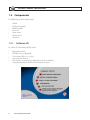
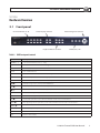
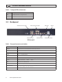
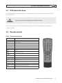
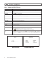
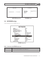
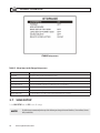
H.264 4-Channel DVR User Manual Product: DMR27U Please read this manual before using your recorder, and always follow the instructions for safety and proper use. Save this manual for future reference. DMR27U_RM Operate this device only in environments where the temperature or humidity is within the recommended range. Operation in extreme temperatures or humidity levels may cause electric shock and shorten the life of the product. Installation and servicing should be performed by qualified and experienced personnel only. DVR should always remain OFF during any installation process. Do not use the camera if fumes, smoke or a strange odor is emitted from the unit, or if it seems to function incorrectly. Disconnect the power source immediately, and consult your dealer. CAUTION CAUTION CAUTION LEGAL NOTICE Supercircuits products are designed to meet safety and performance standards with the use of specific Supercircuits authorized accessories. Supercircuits disclaims liability associated with the use of non-Supercircuits authorized accessories. The recording, transmission, or broadcast of any person’s voice without their consent or a court order is strictly prohibited by law. Supercircuits makes no representations concerning the legality of certain product applications such as the making, transmission, or recording of video and/or audio signals of others without their knowledge and/or consent. We encourage you to check and comply with all applicable local, state, and federal laws and regulations before engaging in any form of surveillance or any transmission of radio frequencies. Other trademarks and trade names may be used in this document to refer to either the entities claiming the marks and names or their products. Supercircuits, Inc. disclaims any proprietary interest in trademarks and trade names other than its own. No part of this document may be reproduced or distributed in any form or by any means without the express written permission of Supercircuits, Inc. © 2012 Supercircuits, Inc. All rights reserved. 11000 N. Mopac Expressway, Building 300, Austin, TX 78759 For Sales and Support, please contact your distributor. ii www.supercircuits.com Table of Contents SECTION 1 SECTION 2 SECTION 3 SECTION 4 SECTION 5 SECTION 6 SECTION 7 Product Description. . . . . . . . . . . . . . . . . . . . . . . . . . . . . . . . . . . . . . . . . . . . . . . . . . . . . . . . . . . . . . . . . . . . . . . . . . . . . . . 1 1.1 Features. . . . . . . . . . . . . . . . . . . . . . . . . . . . . . . . . . . . . . . . . . . . . . . . . . . . . . . . . . . . . . . . . . . . . . . . . . . . . . . . . . . 1 1.2 Components. . . . . . . . . . . . . . . . . . . . . . . . . . . . . . . . . . . . . . . . . . . . . . . . . . . . . . . . . . . . . . . . . . . . . . . . . . . . . . . 2 Hardware Overview. . . . . . . . . . . . . . . . . . . . . . . . . . . . . . . . . . . . . . . . . . . . . . . . . . . . . . . . . . . . . . . . . . . . . . . . . . . . . . . 3 2.1 Front panel. . . . . . . . . . . . . . . . . . . . . . . . . . . . . . . . . . . . . . . . . . . . . . . . . . . . . . . . . . . . . . . . . . . . . . . . . . . . . . . . 3 2.2 Backpanel. . . . . . . . . . . . . . . . . . . . . . . . . . . . . . . . . . . . . . . . . . . . . . . . . . . . . . . . . . . . . . . . . . . . . . . . . . . . . . . . . 4 2.3 DVR Hard disk drive. . . . . . . . . . . . . . . . . . . . . . . . . . . . . . . . . . . . . . . . . . . . . . . . . . . . . . . . . . . . . . . . . . . . . . . . . 5 2.4 Remote control. . . . . . . . . . . . . . . . . . . . . . . . . . . . . . . . . . . . . . . . . . . . . . . . . . . . . . . . . . . . . . . . . . . . . . . . . . . . . 5 System Setup . . . . . . . . . . . . . . . . . . . . . . . . . . . . . . . . . . . . . . . . . . . . . . . . . . . . . . . . . . . . . . . . . . . . . . . . . . . . . . . . . . . . 6 3.1 SETUP screen . . . . . . . . . . . . . . . . . . . . . . . . . . . . . . . . . . . . . . . . . . . . . . . . . . . . . . . . . . . . . . . . . . . . . . . . . . . . . . 6 3.2 LIVE mode setup options . . . . . . . . . . . . . . . . . . . . . . . . . . . . . . . . . . . . . . . . . . . . . . . . . . . . . . . . . . . . . . . . . . . . 7 3.3 RECORD setup options. . . . . . . . . . . . . . . . . . . . . . . . . . . . . . . . . . . . . . . . . . . . . . . . . . . . . . . . . . . . . . . . . . . . . . . 8 3.4 SYSTEM SETUP mode . . . . . . . . . . . . . . . . . . . . . . . . . . . . . . . . . . . . . . . . . . . . . . . . . . . . . . . . . . . . . . . . . . . . . . 11 3.5 NETWORK setup. . . . . . . . . . . . . . . . . . . . . . . . . . . . . . . . . . . . . . . . . . . . . . . . . . . . . . . . . . . . . . . . . . . . . . . . . . . 13 3.6 STORAGE mode. . . . . . . . . . . . . . . . . . . . . . . . . . . . . . . . . . . . . . . . . . . . . . . . . . . . . . . . . . . . . . . . . . . . . . . . . . . 15 3.7 SAVE SETUP. . . . . . . . . . . . . . . . . . . . . . . . . . . . . . . . . . . . . . . . . . . . . . . . . . . . . . . . . . . . . . . . . . . . . . . . . . . . . . 16 LIVE and SEARCH Modes. . . . . . . . . . . . . . . . . . . . . . . . . . . . . . . . . . . . . . . . . . . . . . . . . . . . . . . . . . . . . . . . . . . . . . . . . . 17 4.1 LIVE window. . . . . . . . . . . . . . . . . . . . . . . . . . . . . . . . . . . . . . . . . . . . . . . . . . . . . . . . . . . . . . . . . . . . . . . . . . . . . . 17 4.2 SEARCH window . . . . . . . . . . . . . . . . . . . . . . . . . . . . . . . . . . . . . . . . . . . . . . . . . . . . . . . . . . . . . . . . . . . . . . . . . . 18 4.3 Play mode. . . . . . . . . . . . . . . . . . . . . . . . . . . . . . . . . . . . . . . . . . . . . . . . . . . . . . . . . . . . . . . . . . . . . . . . . . . . . . . . 22 Archiving and Backup . . . . . . . . . . . . . . . . . . . . . . . . . . . . . . . . . . . . . . . . . . . . . . . . . . . . . . . . . . . . . . . . . . . . . . . . . . . . 24 5.1 Archiving still images . . . . . . . . . . . . . . . . . . . . . . . . . . . . . . . . . . . . . . . . . . . . . . . . . . . . . . . . . . . . . . . . . . . . . . 24 5.2 BACKUP still images or video clip to a USB memory stick. . . . . . . . . . . . . . . . . . . . . . . . . . . . . . . . . . . . . . . . . 26 5.3 Playing Backup video . . . . . . . . . . . . . . . . . . . . . . . . . . . . . . . . . . . . . . . . . . . . . . . . . . . . . . . . . . . . . . . . . . . . . . 27 Software Maintenance. . . . . . . . . . . . . . . . . . . . . . . . . . . . . . . . . . . . . . . . . . . . . . . . . . . . . . . . . . . . . . . . . . . . . . . . . . . . 30 6.1 Firmware upgrade. . . . . . . . . . . . . . . . . . . . . . . . . . . . . . . . . . . . . . . . . . . . . . . . . . . . . . . . . . . . . . . . . . . . . . . . . 30 6.2 Backup the setup configuration. . . . . . . . . . . . . . . . . . . . . . . . . . . . . . . . . . . . . . . . . . . . . . . . . . . . . . . . . . . . . . 31 6.3 Load setup configuration. . . . . . . . . . . . . . . . . . . . . . . . . . . . . . . . . . . . . . . . . . . . . . . . . . . . . . . . . . . . . . . . . . . 32 MClient – Network Client Viewer . . . . . . . . . . . . . . . . . . . . . . . . . . . . . . . . . . . . . . . . . . . . . . . . . . . . . . . . . . . . . . . . . . 33 7.1 Overview. . . . . . . . . . . . . . . . . . . . . . . . . . . . . . . . . . . . . . . . . . . . . . . . . . . . . . . . . . . . . . . . . . . . . . . . . . . . . . . . . 33 7.2 MClient Installation. . . . . . . . . . . . . . . . . . . . . . . . . . . . . . . . . . . . . . . . . . . . . . . . . . . . . . . . . . . . . . . . . . . . . . . . 34 7.3 PC MClient setup configuration options . . . . . . . . . . . . . . . . . . . . . . . . . . . . . . . . . . . . . . . . . . . . . . . . . . . . . . . 36 7.4 MClient – Live view. . . . . . . . . . . . . . . . . . . . . . . . . . . . . . . . . . . . . . . . . . . . . . . . . . . . . . . . . . . . . . . . . . . . . . . . 40 H.264 4-Channel DVR User Manual iii 7.5 MClient – search and playback view. . . . . . . . . . . . . . . . . . . . . . . . . . . . . . . . . . . . . . . . . . . . . . . . . . . . . . . . . . 41 Network – IE Browser Viewer . . . . . . . . . . . . . . . . . . . . . . . . . . . . . . . . . . . . . . . . . . . . . . . . . . . . . . . . . . . . . . . . . . . . . 44 8.1 Connect to the DVR, download and install Web Viewer . . . . . . . . . . . . . . . . . . . . . . . . . . . . . . . . . . . . . . . . . . 44 8.2 LIVE mode. . . . . . . . . . . . . . . . . . . . . . . . . . . . . . . . . . . . . . . . . . . . . . . . . . . . . . . . . . . . . . . . . . . . . . . . . . . . . . . . 45 8.3 Search and PLAYBACK mode . . . . . . . . . . . . . . . . . . . . . . . . . . . . . . . . . . . . . . . . . . . . . . . . . . . . . . . . . . . . . . . . 46 SECTION 9 Specifications. . . . . . . . . . . . . . . . . . . . . . . . . . . . . . . . . . . . . . . . . . . . . . . . . . . . . . . . . . . . . . . . . . . . . . . . . . . . . . . . . . . 49 APPENDIX A HDD Compatibility List. . . . . . . . . . . . . . . . . . . . . . . . . . . . . . . . . . . . . . . . . . . . . . . . . . . . . . . . . . . . . . . . . . . . . . . . . . . . 50 APPENDIX B Install FFDSHOW Codec. . . . . . . . . . . . . . . . . . . . . . . . . . . . . . . . . . . . . . . . . . . . . . . . . . . . . . . . . . . . . . . . . . . . . . . . . . . 52 SECTION 8 iv www.supercircuits.com SECTION 1: PRODUCT DESCRIPTION SECTION 1 Product Description The DMR27U is a professional, security grade, real-time, 4-channel digital video recorder. It includes H.264 digital technology providing increased recording capacity, enhanced image quality, and faster video transfer for remote viewing. Recording can be triggered manually, by alarm, by motion detection, or by a preset timer. User friendly on-screen menu displays provide controls for color, brightness and contrast for each camera. The optional 1TB SATA hard drive can store up to 7200 hours of video recorded from all 4 channels. 1.1 Features Your DVR includes the following special features: • • • • • • • • • • • • • • • • • • • • 4-channel, real-time live display and 4-channel simultaneous playback H.264 technology – Advanced recorded picture quality and data compression TRIPLEX – Simultaneous recording, payback, and remote viewing (networking). NaFS file system developed for preventing data loss from power failures Real Time Operating System and simplified hardware with a watchdog timer to ensure reliability Individual channel recording and playback with different frame rates High-quality live and playback resolution Multi-site management supported by CMS application Network via LAN, DHCP, DDNS, ADSL. Dynamic and static IP addresses supported User-friendly setup menu with graphic user interface Easy to implement weekly recording schedule On-screen display (OSD) icons provide helpful and well-explained information Motion detection within a 14 x 10 motion zone grid (each camera) USB port for JPEG, H.264 data backup and software upgrade using a USB memory stick Still image capture and review in JPEG format Operating controls on the front panel and remote control Password required for access Video loss detection Backup allows still-images and AVI data copying to a USB memory stick or network drive Multi-Language support H.264 4-Channel DVR User Manual 1 SECTION 1: PRODUCT DESCRIPTION 1.2 Components The DVR package contains the following items: • • • • • • • DVR unit QSG (Quick Setup Guide) DVR power adapter Power cord Remote control AAA batteries (2) Software CD 1.2.1 Software CD The software CD included with your DVR contains: • • • • • • 2 Quick Installation Guide FFDSHOW codec (see Appendix B) Client Software (MClient, see Section 7) User manual (this document) HDD calculator – for determining recording capacity of your hard disk drive Link to download Adobe Acrobat Reader for viewing documentation www.supercircuits.com SECTION 2: HARDWARE OVERVIEW SECTION 2 Hardware Overview 2.1 Front panel Channel Number (1~0) Video Display Controls Menu Navigation Controls Playback Motion Controls SETUP, ESC, PTZ Table 1. DVR front panel controls Name Description NUMBER (1~0) Select channel with number button (1 ~ 4 only) SEQ Auto sequence of channels in full screen mode. (Toggle) PTZ Enter PTZ (Pan, Tilt, Zoom) mode for PTZ enabled cameras SETUP Enter SYSTEM SETUP menu SEARCH Enter Search menu.--> Event search / Timeline search / Log / Archive search / II Can be use as “Play” and “Pause” function during playback BACKUP Archive in LIVE (backup Live picture) or PLAYBACK (backup picture and video) modes. tt Rewind the footage at 1x, 2x, and 4x speed in PLAYBACK mode. t Jump/Step backward. – In PLAYBACK mode, the playback position moves 60 seconds backward u Jump/Step forward – In PLAYBACK mode, the playback position moves 60 seconds forward. uu Fast forward the footage at 1x, 2x, and 4x speeds in PLAYBACK mode REC Start and stop recording manually UP () Scroll up in the system menu or select camera 1 in LIVE mode. It is also used to enter the number 1. RIGHT (u) Move right, change values in system menu, or select camera 2 in LIVE mode. It is also used to enter the number 2. DOWN () Scroll down in the system menu or select camera 3 in LIVE mode. It is also used to enter the number 3. LEFT (t) Move left, change values in system menu, or select camera 4 in LIVE mode. Also used to enter the number 4. Enter Select full screen or quad view in LIVE display mode ESC Return or cancel command H.264 4-Channel DVR User Manual 3 SECTION 2: HARDWARE OVERVIEW Table 2. Front panel LEDs and connectors Name Description HDD Solid light when DVR is accessing the hard disk. POWER Solid light when DVR is powered on. USB USB port for backup and software updates. 2.2 Backpanel Audio Channel Inputs Video Channel Inputs Audio Out Port VGA Out Ports Ethernet Power VGA/CVBS Switch DVR rear panel Table 3. Rear panel connectors and switches 4 Label Operation VIDEO IN 4 channel connectors for video input. Connect camera output to Video-in. VIDEO OUT 1 connector for video output. VGA Connector for VGA monitor AUDIO Audio 1~4:AUDIO IN/ADUIO OUT SENSOR IN Connection for sensor device ALARM OUT 1 alarm device output. Provides simple On/Off switching by using relay. 0.5A/125V, 1A/30V RS-485 Connect to PTZ camera, + PTZ D+ . – PTZ D– LAN RJ-45 connector for LAN connection DC 12V Apply 12V DC using the DC adapter supplied with the recorder VGA / CVBS switch Select either VGA monitor or CVBS (Composite Video Blanking Sync) monitor. DO NOT CHANGE THIS SETTING WHEN DVR IS ON. DVR MUST REBOOT IF THIS SWITCH IS CHANGED. T-ON/ T-OFF switch For manufacture use only www.supercircuits.com SECTION 2: HARDWARE OVERVIEW 2.3 DVR Hard disk drive The hard disk drive (HDD) included in your system is a security grade device, factory tested and certified to be functional for all operations of the DVR. Do not open the cover of your DVR. Opening the cover will void the warranty. CAUTION If you need to change the HDD installed in your DVR (voids warranty), refer to the HDD Compatibility List in Appendix A for recommended models. 2.4 Remote control Table 4. Remote control controls Button Description ID DVR ID setup REC Record manually NUMBER Press number button to select channel tt Fast Rewind uu Fast Forward u/ II Play/Pause u PTZ/ Jump/Step forward t Jump/Step backward SEL Enter DIRECTION Direction or number 1 to 4 SETUP Setup menu screen SEARCH Search menu screen ESC Esc BACKUP Archive and backup still image or video clip. SEQ Sequential channel conversion H.264 4-Channel DVR User Manual 5 SECTION 3: SYSTEM SETUP SECTION 3 System Setup Use the SETUP menu options to configure your DVR to perform optimally within your installation environment and to meet your specific security needs. 3.1 SETUP screen After pressing the SETUP button, the DVR will prompt you for password. The default password is 1111. Supercircuits highly recommends that the DVR password be changed during initial setup. CAUTION Use the menu navigation buttons (up , right u , down , and left t representing 1, 2, 3, and 4 respectively) or the number keys to enter the password, then press ENTER for password validation. 1 4 2 3 Menu navigation buttons After the password is entered, the SETUP icons will appear Use the navigate buttons to select a SETUP item. Press ENTER to open the menu and set options. 6 www.supercircuits.com SECTION 3: SYSTEM SETUP 3.2 LIVE mode setup options In the LIVE mode menu you can adjust how video images from the cameras appear on the monitor. Navigate through the menu items by pressing the and buttons. Use the t and u buttons to modify a setting. Setup LIVE screen H.264 4-Channel DVR User Manual 7 SECTION 3: SYSTEM SETUP Table 5. Menu items in LIVE mode setup Item Description OSD Enable/disable on-screen displays (OSD). SEQUENCE Enable/disable sequential display of video channels in full screen mode. SEQ-DWELL TIME Dwell time for each channel display in sequential display mode. EVENT BEEP Enable/disable internal beep alert sound. OSD CONTRAST Set the visibility level of the OSD. CHANNEL Select the channel for applying the following settings. DISPLAY Enable/disable display of the video channel in LIVE mode. SEQ LIST Enable/disable the specified channel shown in sequential display mode. BRIGHTNESS Change the brightness level for the specified channel. CONTRAST Change the contrast level for the specified channel. HUE Change the hue level for the specified channel. SATURATION Change the saturation level for the specified channel. VGA SCREEN MODE Select VGA screen mode as either FULL or Normal. Table 6. Event BEEP alarm/motion function Event Beep On Event Beep Off Buzzer Relay Out Buzzer Relay Out Alarm Yes Yes No Yes Motion Yes Yes No Yes NOTE The “Event Beep” function is NOT related to relay output. Relay output is setup in the RECORD menu. 3.3 RECORD setup options Set the options for recording video from each channel. Navigate through menu items by pressing the and buttons. Change the value of the menu item with the t and u buttons. 8 www.supercircuits.com SECTION 3: SYSTEM SETUP Setup RECORD screen Table 7. Menu items in Setup RECORD Menu item Description RESOLUTION Set resolution to either 704 x 480 or 352 x 240 CHANNEL Select the camera channel for which these settings apply FRAME RATE Set the frame rate for the specified channel. The sum of the frames rates of all channels cannot exceed maximum frame rate for the resolution selected. Maximum frame rates are 120 fps for 352 x 240 resolution and 30 fps for 704 x 480 resolution. QUALITY Select the recording quality for the specified channel from NORMAL / HIGH / SUPER. RECORDING Assign the recording mode for each channel: CONTINUOUS / BY MOTION / BY SENSOR / BY SCHEDULE / DISABLE. MOTION ZONE Select FULL ZONE or PARTIAL ZONE motion sensing. If PARTIAL ZONE is chosen, the screen changes to enable/disable motion sensing in each of 140 (14 x 10) image segments. MOTION SENSITIVITY Set the motion sensitivity for the specified channel. Adjust the motion sensitivity from 1 to 9. SENSOR TYPE Set the sensor type for the channel to either “–“ (none), N/O (normal open), or N/C (normal closed). PRE RECORD Enable/disable pre-event recording. Pre-event recording time is 3 sec. Only intra-frames are recorded for pre-event recording. POST EVENT RECORD Set post event recording time duration up to 30 seconds for the specified channel ALARM Enable/disable alarm generation for the specified channel ALARM DURATION Set alarm time duration for the specified channel AUDIO Enable/disable audio for the specified channel SCHEDULE Set recording schedule H.264 4-Channel DVR User Manual 9 SECTION 3: SYSTEM SETUP NOTE To receive smooth video during playback, set the frame rate of each channel for more than 3 fps. Switch to full screen during playback when audio recording is enabled. 3.3.1 PARTIAL ZONE settings After selecting PARTIAL ZONE in the MOTION ZONE menu, select the portion of the camera video within which motion sensing will occur. Each block in the MOTION ZONE display shown below represents a specific segment of the camera video image. Use the navigation buttons on the front panel to move to each block, and press Enter button to enable or disable motion sensing in that portion of the video. Areas selected for motion sensing are indicated by a color change of the block. By default, only the area in the middle of the camera video is monitored for motion. Motion Zone selection screen with default selections 3.3.2 RECORD SCHEDULE Select SCHEDULE in the RECORD menu to setup the record schedule for the camera channel. In the SCHEDULE menu, use the navigation buttons on the front panel to move to each option on the screen. [ALL]: Press Enter to apply to the entire time zone and all channels. [SUN to SAT]: Press Enter to apply to the entire time zone for the specified channel. [ENTER]: When a time slot is selected, press ENTER repeatedly to cycle through the options C (continuous), M (motion), S (sensor), or disable recording mode. 10 www.supercircuits.com SECTION 3: SYSTEM SETUP [COPY FROM, COPY TO]: Copy the Record schedule of one channel to another channel. [ESC]: Return to the RECORD setup menu. SCHEDULE recording setup screen 3.4 SYSTEM SETUP mode SYSTEM setup screen H.264 Network IP Camera User Manual 11 SECTION 3: SYSTEM SETUP Table 8. Menu items in SYSTEM SETUP screen Item Description DVR ID The name of the system. Press the ENTER to select this item. Select a character position with the and buttons. Press DESCRIPTION Press ENTER to see system information. LOAD DEFAULT Choose OFF or ON. If selecting ON, press ENTER to load defaults. ADMIN PASSWORD Set the administrator password. The password numbers (1,2,3,4) can be entered with the direction keys or number keys. The default password is 1111. NETWORK PASSWORD Set the network client password. The password numbers (1,2,3,4) can be entered with the direction keys or number keys. The default password is 1111. DATE FORMAT Select the preferred date and time display format. SET DATE & TIME Set the present date and time. If DLS (daylight savings) is ON, user can not enter this menu or change the date and time. PTZ CONTROL Set the camera speed, number, type and ID. KEY TONE Enable/disable the key tone. LANGUAGE Select system language. REMOTE CONTROL ID Select the ID of the remote control. (Default is 0). 1. Select ID from 0 to 9. 2. On a remote control, press the same number as the remote control ID set in DVR. 3. The icon is displayed in the LIVE screen of the DVR that responds to the remote control. DLS Set to ON or OFF for DLS (Daylight Saving) using the t or u buttons. After selecting ON, move the cursor to BEGIN (MM/ DD/HH) and press the SELECT button to set the start time of DLS. Move to END (MM/DD/HH) using p or q button to set the stop time of DLS. CAUTION: DLS can’t start from 23:00. Also, DLS can’t be applied if the BEGIN and END dates are the same. t or u to change the character. DVR ID setup screen 12 www.supercircuits.com Description display screen SECTION 3: SYSTEM SETUP DATE & TIME setup screen PTZ CONTROL screen 3.5 NETWORK setup Setup network parameters on the NETWORK setup screen. NETWORK setup screen Table 9. Menu items in the NETWORK setup screen Item Description PORT Video Port number (default:8000); BACKUP port number is PORT number + 1. WEB PORT IE Browser port number (default: 80) H.264 Network IP Camera User Manual 13 SECTION 3: SYSTEM SETUP Item Description CLIENT ACCESS Set to ON or OFF to enable or disable remote access through client software. BANDWIDTH SAVING Set to ON or OFF for key frame transmission. ON is favorable for use in low-bandwidth networks. Set to OFF for normal use. NETWORK TYPE Set the type of network connection: LAN, DHCP, or ADSL. NOTE: Options presented on the Network Setup screen support the type of network selected. DHCP When DHCP is selected, the DVR gets its IP address from a DHCP server. The IP address may change occasionally. ADSL (PPPoE) A registered ID and Password are required for an ADSL connection. LAN IP: Register IP address that is assigned to the DVR. Gateway: Register Network Gateway. Subnet Mask: Register Network Subnet Mask. DNS Server IP: Register Network DNS Server IP DDNS Support for DynDNS.com SEND-E-MAIL Send e-mail when IP address changes or an Event happens. 3.5.1 Ports For remote access (from outside the LAN or the Internet) to one or more DVRs connected to the same IP sharing device (LAN), each DVR must be assigned a unique WEB PORT number. The WEB PORT number in the NETWORK setup screen is the port assigned to the DVR in the IP sharing device (router). Additionally the DVR requires two additional ports on the IP sharing device: one to transmit video and the other to transmit BACKUP files. The video port number is defined in the PORT entry, and the BACKUP port number is always the PORT number +1. For instance, in the NETWORK screen shown above, the PORT number is 5445, so the DVR will use port 5446 for BACKUP. The ports defined for a DVR, including the PORT, WEB PORT, and BACKUP (WEB PORT +1) must not be used by other device on the local network. To access the DVR from outside the local network, the network router the must be setup to “port forward” (associate) these three ports to the IP address of the DVR. For more information on port forwarding, see http://portforward.com/. 3.5.2 Network types The DVR supports three types of networks: LAN, DHCP, and ADSL. LAN In a LAN configuration the IP address of the DVR is static (fixed). If your LAN is maintained by a network administrator, obtain the static IP address from the administrator. DHCP Select DHCP when the IP address is automatically assigned by the DHCP server. The DHCP server assigns the IP address and other parameters automatically to devices on the LAN not configured with static (unchanging) IP addresses. 14 www.supercircuits.com SECTION 3: SYSTEM SETUP ADSL (PPPOE) Select the Asymmetric Digital Subscriber Line (ADSL) Point to Point over Ethernet (PPPoE) option when the network type connected to the DVR is PPPoE. Table 10. ADSL parameters Item Description ID The user ID for an ADSL connection PASSWORD The password for an ADSL connection When the DVR is installed on an IP sharer connected with ADSL, a user can assign a static IP address to the DVR from an IP sharer using the “DMZ” function. 3.5.3 SEND E-MAIL notification options E-mail notification options include: • • • • • • • IP Notification: DVR will send an e-mail notification to recipient automatically if IP changes. EVENT ALARM: DVR will send an e-mail notification to recipient automatically if an event detected. MAIL ADDRESS: Recipient e-mail address MAIL SERVER name: Recipient e-mail server address ID: Recipient e-mail login ID PASSWORD: Recipient e-mail login password RETURN MAIL ADDRESS: Sender e-mail address 3.6 STORAGE mode Set the recording mode, initiate an HDD reformat, and save setup settings to a USB device in the STORAGE setup menu. H.264 Network IP Camera User Manual 15 SECTION 3: SYSTEM SETUP STORAGE setup screen Table 11. Menu items in the Storage Setup screen Item Description OVERWRITE Overwrite existing data when the hard disk drive is full FORMAT Format the hard disk drive USB UPGRADE DVR firmware can be upgraded through the USB port via USB memory stick. See paragraph 6.1. SAVE SETUP TO A USB User can save the DVR configuration to a USB memory stick. See paragraph 6.2. LOAD SETUP FROM A USB Upload/restore the DVR configuration using the USB memory stick. See paragraph 6.3. VIDEO DELETE Enable/disable recording limit. DELETE VIDEO AFTER Set the time limit for a recording to reside on the hard disk drive (from 1 to 60 days). 3.7 SAVE SETUP Select SAVE SETUP and click YES to save all settings. NOTE 16 The DVR reboots automatically when any of the following are changed: Network IP address, Time and Date, Format HDD, Load default. www.supercircuits.com SECTION 4: LIVE AND SEARCH MODES SECTION 4 LIVE and SEARCH Modes 4.1 LIVE window LIVE window Table 12. Screen icons in LIVE window Icon Description C Continuous recording in progress R Manual recording in progress M Motion recording is triggered S Sensor recording is triggered Indicates the HDD is overwriting Indicates alarm output is activated. Event indicator. When there is an alarm (sensor alarm or motion alarm) in the video channel, this icon is red. H.264 Network IP Camera User Manual 17 SECTION 4: LIVE AND SEARCH MODES Icon Description Indicates that a network client is connecting to the DVR. Indicates that sequencing mode is enabled. Graphical representation of the fullness of the HDD. The icon will appear when it matches with remote control ID. 4.2 SEARCH window In LIVE mode, press SEARCH and enter the password to open the SEARCH screen. Use the arrow buttons or remote control to enter the password. SEARCH window 4.2.1 EVENT Search The Event Search window is used to find stored video. Three categories of search filters can be applied: DATE, CHANNEL and TYPE. Use the p and q buttons move through the options and press ENTER to select a one. Press ESC to return to the previous screen. 18 www.supercircuits.com SECTION 4: LIVE AND SEARCH MODES 1. In the SEARCH window, use the p and q buttons to move highlight EVENT SEARCH. Press ENTER. 2. Use the navigation buttons to move to the date of the target surveillance video event. SEARCH window select channel 3. Press ENTER to select the date to move to the CHANNEL selector. 4. Use t and u buttons to change the channel selection from ALL to any one of the available channels. Press ENTER to select the CHANNEL and move to the TYPE selector. 5. Use the t and u buttons to change the TYPE of recording to A (All Event Recording), M (Motion Recording), S (Sensor Recording), M (Manual Recording), or C (Continuous Recording). Press ENTER to show the search results. LIST search criteria 6. To find the target surveillance event, use the p and q buttons to scroll through the listings, and the t and u buttons to display a list of recordings made previously to or after the current selection. H.264 Network IP Camera User Manual 19 SECTION 4: LIVE AND SEARCH MODES After the target event is selected, press ENTER to start video playback. In PLAYBACK mode, you can press the CAPTURE (BACKUP) button to launch the archiving function. 7. 4.2.2 TIMELINE Search The TIMELINE search window displays a graph that show when video and audio data was recorded. 1. In the SEARCH window, use the p and q buttons to highlight TIMELINE SEARCH. Press ENTER. 2. In the SEARCH TIMELINE window, use the navigation buttons to highlight the date of the target surveillance video event. SEARCH date, timeline screens NOTE In the SEARCH timeline window, the RED Bar indicates when video data was recorded, the GREEN Bar indicates when audio data was recorded. 3. Press ENTER to select the date and open the timeline SEARCH window. 4. Use directional buttons to select a start time. Press ENTER to move to the 60 minutes time table. 5. Use the t and u buttons to select the duration. Press ENTER. 6. Use the p and q buttons to Select All, or select a specific channel to search. 7. Press ENTER to playback the recorded video. 4.2.3 GO TO search You can directly specify a day and time at which to start video playback. Use the t or u buttons to move across the date – time field, and p or q buttons to change the date and time settings. 20 www.supercircuits.com SECTION 4: LIVE AND SEARCH MODES GO TO SEARCh window 4.2.4 GO FIRST time You can access the first data recorded on the HDD using this option. 4.2.5 GO LAST time You can access to the last data recorded on the HDD using this option. 4.2.6 LOG The LOG option provides a list of user actions. LOG option list H.264 4-Channel DVR User Manual 21 SECTION 4: LIVE AND SEARCH MODES 4.2.7 ARCHIVE The ARCHIVE search window is used to find a stored video. 1. In the SEARCH window, use the p and q buttons to highlight ARCHIVE. Press ENTER. 2. In the SEARCH window, use the navigation buttons to move to the date of the archived video events. Press ENTER to select the date and open the LIST window. SEARCH Archived video 3. Use the p or q button to scroll through the list and find the target event. 4. Press ENTER to see the selected capture or video (in paused mode). Press BACKUP to copy the capture or video to USB memory stick. If video is being copied, select the video type (format) of the clip – AVI or DVR. After a successful backup, a SAVE SUCCESS message appears. NOTE When saving a video clip in DVR format, Player.exe is copied to the memory stick. Use this application to watch the video clip. 4.3 Play mode Several front panel controls are useful when playing recorded video (see the table below). While playing recorded video, return to SEARCH by pressing ESC. 22 www.supercircuits.com SECTION 4: LIVE AND SEARCH MODES Play mode Table 13. Button functions in Play mode Button Description ESC Return to the previous menu screen or exit from the SETUP menu Press to play video in reverse at 1x, 2x, and 4x speeds. Reverse playback speed is shown at the lower right corner of the screen as -1x (normal), -2x (2 times normal), and -4x (4 times normal). Press to play video forward at 1x, 2x, 4x, and 8x speeds. Playback speed is indicated at the lower right corner of the screen as +1x, +2x, +4x, and +8x for normal, twice, 4 times, and 8 times normal speed. / II Press to play / pause recorded video. -- Jump/Step forward. Playback position moves 60 seconds forward. -- Jump/Step backward. Playback position moves 60 seconds backward. Use to select channel 1 to 4 in full screen mode or change to quad display by directional button. ENTER Switch between full screen and current display mode. H.264 4-Channel DVR User Manual 23 SECTION 5: ARCHIVING AND BACKUP SECTION 5 Archiving and Backup To BACKUP a still image or video clip to a USB storage device, it must first be archived on the HDD. 5.1 Archiving still images Still images can be captured and archived to a USB memory stick or hard drive while in LIVE mode and while playing back recorded video. The image saved is in .jpg format, and associated with the date and time the image was captured. The USB memory stick used for backup must be formatted as FAT32. 5.1.1 Archive and backup still images in LIVE mode To archive and backup still images in LIVE mode: 1. Insert a USB memory stick with FAT32 format into the USB port on the front of the DVR. 2. Press BACKUP. The DVR will archive the image on the screen. 3. Wait for the message SAVING or CHECK FAIL to close before removing the USB memory stick. SAVING indicates that the DVR is writing the archived file to the USB memory stick. CHECK FAIL indicates that the attempted backup to the USB memory stick failed. 4. Unplug the USB memory stick from the DVR. 5.1.2 ARCHIVE and BACKUP in PLAYBACK mode Video clips must be archived before they can be backed up. To archive recorded video: 1. Insert a USB memory stick with FAT32 format into the USB port on the front of the DVR. 2. Press SEARCH. Use the directional buttons on the DVR to enter the password, and then press ENTER. 3. Use the up and down directional buttons to highlight the preferred search method: EVENT SEARCH, TIMELINE SEARCH, GO TO, GO FIRST, or GO LAST. Press ENTER. 4. Locate and select the video portion you want to Archive. (See “SEARCH window” in paragraph 4.2.) 24 www.supercircuits.com SECTION 5: ARCHIVING AND BACKUP 5. Press ENTER to play the video clip. 6. Press BACKUP. 7. At the ARCHIVE prompt, use the left t or u buttons to highlight STILL or VIDEO. 8. Press ENTER, 9. If backing up a video clip: a. NOTE b. Use the t or u buttons to highlight the channel you want to archive. Only one camera can be backed up at a time. Use the directional buttons to select a single channel. The DVR will stop recording during backup. DVR can backup up to 1800 sec. (30 min.) at a time. Press the button to highlight OK. Press ENTER. H.264 4-Channel DVR User Manual 25 SECTION 5: ARCHIVING AND BACKUP c. At the DURATION prompt, enter the video clip duration in seconds by using the t or u buttons to select a digit, and the or buttons to select the value (0 – 9) of the digit. Maximum: 1800 seconds / 30 minutes d. Press ENTER. A VIDEO OK message will flash. e. When the VIDEO TYPE prompt appears, use the t or u buttons to highlight AVI or DVR (file format). f. Press ENTER to backup the video clip to the USB memory stick. 10. After the SAVE SUCCESS message appears, press ESC to exit. 11. Unplug the USB memory stick from the DVR. 5.2 BACKUP still images or video clip to a USB memory stick To BACKUP a still image or video clip the data must first be archived. To perform the BACKUP: 1. 26 Insert a USB memory stick with FAT32 format into the USB port on the front of the DVR. www.supercircuits.com SECTION 5: ARCHIVING AND BACKUP 2. Use Search and Archive functions to locate and play the target still image or video clip. ARCHIVE and LIST screens 3. While the still image or video clip is playing, press BACKUP. 4. If backing up a video clip: a. Use the t or u buttons to highlight AVI or DVR (file format) when VIDEO TYPE appears. b. Press ENTER to backup the video clip to the USB memory stick. A VIDEO OK message will flash. 5. After the SAVE SUCCESS message appears, press ESC to return to the Archive list. 6. Unplug the USB memory stick from the DVR. 5.3 Playing Backup video Video backed up to a USB memory stick can be played on a personal computer. The backed up video may be in AVI or DVR (NaFS) format. 5.3.1 Playing Backup video in AVI format Most MS Windows based PCs include a player for files in AVI format. However, if your computer will not play the AVI file correctly, install the FFDSHOW codec. An FFDSHOW codec installer is included on the DVR CD (see Appendix B). H.264 4-Channel DVR User Manual 27 SECTION 5: ARCHIVING AND BACKUP 5.3.2 Playing video backup in DVR format Video backed up in DVR format can be played on a PC with Microsoft Windows using the Player.exe player. Player.exe player is copied to the USB device when you backup a DVR formatted file. To play these files: 1. Insert the USB memory stick with the backed up video into a USB port on your computer. 2. Open the file system on the USB stick with Windows Explorer. 3. Find the directory named with a date code representing the day of the video clip. The directory is named using the format <year><month number><day> (yyyymmdd). Example: 20100201 was recorded on February 2, 2010. Video files in that directory saved in DVR (NaFS) format have filename extension .dvr 4. Double-click player.exe to open the application. Open media file Play 5. Click the open media file icon located in the lower left corner of the Player window. 6. In the Open Media File window, browse the USB memory stick to find the .dvr file you want to play. Click Open. 7. In the Player window, click the Play icon to watch the video. 28 www.supercircuits.com SECTION 5: ARCHIVING AND BACKUP Playback speed Open media file Date/Time of data Filename Screen size controls Volume control Playback controls VIIEWER.exe Player window NOTE To change playback speed, click the icon in the Playback controls. To select full screen playback, click “F”. H.264 4-Channel DVR User Manual 29 SECTION 6: SOFTWARE MAINTENANCE SECTION 6 Software Maintenance 6.1 Firmware upgrade To upgrade DVR firmware, please contact your distributor to obtain the firmware file and for assistance: 1. Obtain the new firmware file from your distributor. 2. Obtain a USB memory stick with a capacity of 1 GB or larger. 3. Format the memory stick to FAT32. 4. Create a folder on the USB memory stick named “upgrade”. 5. Copy the new firmware file to the upgrade folder on the USB memory stick. 6. On the DVR, press the SETUP button and enter the password. 7. Open the STORAGE window. STORAGE screen 8. 30 Plug the USB memory stick into the USB port on the front of the DVR. www.supercircuits.com SECTION 6: SOFTWARE MAINTENANCE 9. On the STORAGE window, select USB UPGRADE and press ENTER. DVR will upgrade to the new firmware automatically 10. Respond to the screen prompts to allow the USB firmware upgrade process to complete. STORAGE setup - USB UPGRADE 6.2 Backup the setup configuration To backup the DVR setup information, do the following: 1. Obtain a USB memory stick with a capacity of 1 GB or larger. 2. Format the memory stick to FAT32. 3. Insert the USB memory stick into the USB port on the front of the DVR. 4. On the STORAGE window, select SAVE SETUP TO A USB STICK and press ENTER. H.264 4-Channel DVR User Manual 31 SECTION 6: SOFTWARE MAINTENANCE 5. Wait until the process completes. A CHECK SUCCESS message will appear. STORAGE setup - SAVE SETUP TO A USB STICK 6.3 Load setup configuration To restore backed up setup configuration data, do the following: 1. Insert a USB memory stick containing backed up setup configuration data into the USB port on the front of the DVR. 2. On the STORAGE window, select LOAD SETUP FROM A USB STICK and press ENTER. 3. Wait until the process completes. A LOAD SUCCESS message will appear. STORAGE setup - LOAD SETUP 32 www.supercircuits.com SECTION 7: MCLIENT – NETWORK CLIENT VIEWER SECTION 7 MClient – Network Client Viewer The DVR provides LIVE remote viewing and other features using the MClient software provided on the CD with your DVR, and with the Microsoft® Internet Explorer (IE) browser. NOTE On a high-bandwidth network, up to four users can access one DVR simultaneously. On a low bandwidth network, not more than one user should access the DVR at any time. During remote viewing the video frame rate is limited to 1 frame/sec when the DVR is not recording. When the DVR is recording, the video frame rate for remote live viewing is the same as the frame rate at which the DVR is recording. 7.1 Overview The network client viewer MClient supports remote live viewing, search, playback, backup, and recording. Before installing MClient, verify that your PC meets the minimum requirements for the specifications shown in the table below. MClient may not perform correctly if the PC does not meet the minimum requirements. Table 14. PC requirements for remote monitoring PC specification Minimum requirement Recommended CPU Intel Pentium III 500 MHz Intel Pentium 4 2GHz Memory 128MB 512MB Video memory 16MB 64MB ® ® Resolution 1024x768 1024x768 OS Windows 2000 Windows XP with SP3, Windows Vista, or Windows 7 Network 10/100BASE-T 10/100BASE-T Others DirectX 8.1 DirectX 9.0c or newer 7.1.1 Remote access If MClient is used outside the local network, the network router must be setup to port forward three ports to the IP address of the DVR; the WEB PORT, PORT, and PORT + 1. These ports numbers are defined in the NETWORK setup options menu. See paragraph 3.5, NETWORK setup. H.264 4-Channel DVR User Manual 33 SECTION 7: MCLIENT – NETWORK CLIENT VIEWER 7.2 MClient Installation To install MClient software: 1. Log into your PC as a user with administration privileges. 2. Insert the Software CD provided with your DVR into the CD or DVD drive of your PC. Normally the window below will appear. DVR Software CD initial window Click INSTALL CLIENT SOFTWARE. 3. NOTE If MClient is already loaded on your PC, clicking INSTALL CLIENT SOFTWARE will remove the existing version. After the removal is complete, click INSTALL CLIENT SOFTWARE again to load the version provided on the CD. 4. Follow the on-screen directions to install MClient. An MClient icon, 5. Double click the MClient icon to start the application. 34 www.supercircuits.com , will appear on the PC desktop. SECTION 7: MCLIENT – NETWORK CLIENT VIEWER Connect/ Disconnect Playback Lock/ Unlock Date/Time HDD Usage Alarm Volume Zoom/Focus Pan/Tilt Setup MClient initial screen Table 15. MClient viewer controls Button Description CONNECT Connect to the DVR PLAYBACK Switch to search for and playback a recorded video. LOCK/ UNLOCK Lock/unlock all operations of the client software. DATE & TIME Display the current date and time. VOLUME Use the volume control bar to set the audio level. Audio can be on or muted by clicking the AUDIO icon. ALARM Alarm indicator. Lights for 5 seconds if the alarm output is activated on the DVR. HDD USAGE DVR HDD storage Indicator. ZOOM/ FOCUS Control ZOOM/ FOCUS features on a remote PTZ camera. PAN/TILT Control PAN/TILT features on a remote PTZ camera. Capture a still image. When the capture icon is clicked, the Image Capture pop-up window appears. The still image can be saved in either JPEG or BMP format. CAPTURE H.264 4-Channel DVR User Manual 35 SECTION 7: MCLIENT – NETWORK CLIENT VIEWER Button Description PLAY/PAUSE Play/pause live video. RECORDING Enable or disable recording of live video to local disk. SETUP Setup configuration of client software. EXIT Exit the client software. 7.3 PC MClient setup configuration options Before using MClient, setup the MClient software configuration. 7.3.1 Setup General options 1. On the MClient screen, click SETUP to open the Setup window. MClient Setup General window 2. In the Security Option frame, select the preferred security conditions and set a password. When you access any of the functions shown, you must enter the password. 3. In the Save Path frame, browse for and select folders where image captures and Backup files are saved. 4. In the Miscellaneous frame, check Automatic reconnection if you want to reconnect to the previously connected IP address after a network connection is lost. 5. Select the Time format you prefer from the options available in the pull-down menu. 36 www.supercircuits.com SECTION 7: MCLIENT – NETWORK CLIENT VIEWER 7.3.2 Setup Site options 1. In the Setup window, click Site to list sites added to the MClient configuration. Sites can be added to this list, and modified or removed by clicking the buttons at the top of the window. MClient Setup Site 2. Click Addition to register another site. See the window below. After parameters are set, click OK to include the entry in the Site list. Double click the Name entry to change the camera name Site Modify window 3. Complete the entries in the Site Addition pop-up window and click OK to create a DVR to connect to. a. Site Name – Enter any name of your choosing for the DVR H.264 4-Channel DVR User Manual 37 SECTION 7: MCLIENT – NETWORK CLIENT VIEWER b. IP Address – Enter the IP address of your DVR. If your DVR and PC are on the same local network, use the IP address shown in the DVR SETUP NETWORK option list. IF you are accessing your DVR across the Internet, enter the IP address of the router (modem) you use to access the internet from your local network. If the WEB PORT option on the DVR SETUP NETWORK option list is not 80, enter the address in the form: <IP>:<WEB PORT> c. Port No. – Enter the PORT number shown in the DVR SETUP NETWORK option list. d. Password – Enter the password assigned setup for your DVR. The default password is 1111. After creating the Site, the entry will appear in the Site list. 7.3.3 Event option In the Setup menu, click Event to specify how events, such as Startup, Shutdown, Camera loss, etc. are treated by MClient. These events can be entered into a LOG (saved in a log file), displayed as an ICON during Live video, or displayed in an EVENT LIST in LIVE mode. The path to and maximum size of the log file is defined in this window. Setup Event window EVENT SEARCH OPTIONS The Setup Event search window displays all logged events within a specified time period. 38 www.supercircuits.com SECTION 7: MCLIENT – NETWORK CLIENT VIEWER 7.3.4 Record options Set the recording method to Always, record on Event (for Motion and/or Alarm events), or Auto record. For Always and Event recording, select all channels or individual channels to record. When the Event method is selected, you can set the event for motion and/or alarm with duration. You can also set each or all channels to record. Setup Record window RECORD DISK OPTIONS In the Setup Record Disk window, select which local disk to use and the disk space to allocate for storage of recordings. Also, choose to overwrite data or stop recording when the allocated disk space is full. H.264 4-Channel DVR User Manual 39 SECTION 7: MCLIENT – NETWORK CLIENT VIEWER Setup Record Disk window 7.3.5 Language In the Setup Language window, select the preferred language from the pull-down list. The default language is English. 7.4 MClient – Live view To view real-time images from your DVR, to the following: 1. Double click the MClient icon on your PC desktop to launch the program. 2. Click CONNECT. See the screen capture below. 3. In the Connect pop-up window, click the down arrow in the Site Name field, or the down arrow in the IP Address field, and select the name or address of the site you want to connect to. 40 www.supercircuits.com SECTION 7: MCLIENT – NETWORK CLIENT VIEWER 4. Click OK. Within a few seconds, real-time images from the DVR will appear. MClient Live view 7.5 MClient – search and playback view When MClient is searching for or playing a recorded video, the controls identified on the following screen are significant. LIVE Date/Time Search Timeline bars MClient search controls H.264 4-Channel DVR User Manual 41 SECTION 7: MCLIENT – NETWORK CLIENT VIEWER Table 16. Main controls in Search Button Description LIVE Switch to Live Video mode. DATE TIME Displays the date and time of the recording selected on the time bar at the bottom of the window. SEARCH calendar The calendar shows dates with recorded video in light blue and the selected date in dark blue. TIMELINE BAR The timeline shows recorded data in dark blue on the bar. Adjust the time-line scale to playback. Click the play icon to display the recorded video. - CAPTURE Capture a still image. When the capture icon is clicked, the Image Capture pop-up window appears. The still image can be saved in either JPEG or BMP format. - MARK IN Set the video backup start time. - MARK OUT Set the video backup end time. - BACKUP Backup the selected recorded video in AVI format. 7.5.1 MClient – backup recorded video in AVI format Use the MClient search viewer to backup recorded video in AVI format: 1. On the MClient search viewer window, set the blue marker on the timeline at the time when you want the backup file to begin recording. Click the Play icon to review the video, if necessary. 2. Click the MARK IN button. 3. Set the ending time by dragging the blue marker on the timeline to the ending time for the backup file. 4. Click the MARK OUT button. The color of the timeline between the beginning time and ending time will change to dark green. 5. Click the BACKUP button. The pop up window shown below will appear. The start and end times can also be set in this window. 42 www.supercircuits.com SECTION 7: MCLIENT – NETWORK CLIENT VIEWER AVI backup specification 6. After selecting a channel for backup, click the OK button. The backup will begin. H.264 4-Channel DVR User Manual 43 SECTION 8: NETWORK – IE BROWSER VIEWER SECTION 8 Network – IE Browser Viewer The DVR provides remote live monitoring, search, and playback of recorded video. An ActiveX™ control provides a viewer (Web Client) that must be downloaded and installed to interact with the DVR. This procedure assumes that the DVR and its network are setup for access from a PC across a local LAN and/or remotely through the Internet. 8.1 Connect to the DVR, download and install Web Viewer To interact with your DVR across a network, do the following: 1. Open a Microsoft Internet Explorer window (tab). 2. In the internet address field of the browser, enter the IP address and web port of your DVR in the format: <IP address>:<port> If the web port number is 80 (default), the <port> entry is not required. If you are accessing your DVR across the Internet using the DynDNS service (convenient for DVRs with dynamic IP addresses), go to the appropriate DynDNS internet address. See www.dynDNS.com for more information about this service. 3. If prompted, follow the prompts to install the program (Web Client) and/or ActiveX control identified by your browser. 4. Follow the screen prompts to complete the install. After install, the Web Client application will open within the browser window. 44 www.supercircuits.com SECTION 8: NETWORK – IE BROWSER VIEWER Connect 5. Click Connect. 6. In the webpage dialog, enter the web IP address of your DVR, the video PORT number (from the Setup SYSTEM menu), and the password. Then click Connect in the Dialog pop-up window. A LIVE mode screen will open. Web Client server (DVR) login 8.2 LIVE mode LIVE mode viewing provides real-time images from the cameras connected to the DVR. A description of the screen controls is provided below. H.264 4-Channel DVR User Manual 45 SECTION 8: NETWORK – IE BROWSER VIEWER Date/Time Disconnect Connect Search Pan/Tilt Zoom/ Focus Connection Status LIVE mode controls Table 17. LIVE mode controls Name Description DATE and TIME Displays the current date and time. CONNECT/ DISCONNECT Connect/disconnect the DVR SEARCH Search for recorded video. PAN and TILT Use these buttons to control the PAN and TILT features of remote camera. ZOOM and FOCUS Use these buttons to control the ZOOM and FOCUS features of remote camera. CONNECTION STATUS Shows the client connection information. Full Screen Switch to full screen PAUSE Pause the display screen. CAPTURE Capture the image from the live display. AUDIO Site audio can be ON or OFF by clicking the Audio button. 8.3 Search and PLAYBACK mode In the web viewer window, click the Search button to change from LIVE mode to search and playback recorded video. 46 www.supercircuits.com SECTION 8: NETWORK – IE BROWSER VIEWER Date/Time Disconnect/ Connect Playback Buttons Search Calendar Video Map Marker Main user interface – search and playback Table 18. Main controls – search and playback Name Description DATE and TIME Displays the current date and time. CONNECT / DISCONNECT Connect / Disconnect to the DVR LIVE Switch to LIVE mode. BACKUP and CAPTURE Capture or backup the image from playback. PLAYBACK BUTTONS Control playback image SEARCH CALENDAR Select data for playback Video Map Shows a timeline of where recorded video exists for the date selected. Marker Sliding bar to set the start of video playback. Full Screen (not shown) Switch to full screen 8.3.1 Playback video To playback recorded video: 1. Click the date in the search calendar. Only days that have recorded video are selectable. H.264 4-Channel DVR User Manual 47 SECTION 8: NETWORK – IE BROWSER VIEWER 2. Slide the marker bar to the time where you want to start playing. 3. Click Play. 8.3.2 Backup video clip To backup recorded video: 1. Click the target date in the Search Calendar. Only days that have recorded video are selectable. 2. Click Backup. A capture/backup webpage dialog window will open. 3. Select each field in From and To and enter the start and end times of the video you want to backup. 4. In the File field, enter the directory where you want to store the backed up video file. 5. Open the Channel pull-down list and select the camera channel of the video you want to back up. 6. Click OK. The progress bar will change as video is downloading to your PC. 48 www.supercircuits.com SECTION 9: SPECIFICATIONS SECTION 9 Specifications Table 19. Specifications Item Video Audio Alarm Specification Input Channel, Input Level 4 channel, Composite 1.0 Vp-p, 75 Ohm Signal Format NTSC Output 1 CH Composite Output / 15 pin D-Sub VGA Output Input / Output 4 Line In / 1 Line Out Sensor Input 4 (NC/NO Selectable) Alarm Output 1 (Alarm, Motion, Video Loss) Compression H.264 Multi-operation TRIPLEX (Playback / Record / Network) Resolution 120 fps (352 x 240) / 30 fps (704 x 480) Recording quality grade NORMAL/HIGH/SUPER Recording Mode Continuous / Schedule / Motion/ Sensor / Manual Motion Detection Motion detection setup by Grid Display Speed Real Time Display Playback Search Mode Event, Archive, Log, Time Line Internal HDD Serial ATA (Up to 1TB) Recording Storage Serial port Network Client S/W General Backup USB 2.0 memory stick JPEG, AVI and DVR file formats Network Video clips and still images Camera Control 1 RS-485 Dynamic IP support Yes Network Interface 10/100BASE-T Ethernet (RJ-45) Functions Live, Search, Backup Power Source 12 Vdc @ 3.3 A Unit Weight 3.5 kg Dimension (W x D x H) 17.1” x 13.2” x 2.1” (435 mm x 335 mm x 54 mm) Temperature Operating: 41 °F ~ 104 °F (5 °C ~ +40 °C) Storage: 14 °F ~ 122 °F (-10 °C ~ +50 °C) Humidity (operating) 0 - 90% H.264 4-Channel DVR User Manual 49 APPENDIX A: HDD COMPATIBILITY LIST APPENDIX A HDD Compatibility List The hard disk drives included in the following table are functionally compatible with the DMR27U hardware and acceptable for security system applications. Table 20. HDD compatibility list Manufacturer Hitachi® Maxtor ® Samsung® 50 Model Capacity Buffer HDS728080PLAT20 80 GB 2 MB HDS721680PLAT80 80 GB 8 MB HDT722516DLAT80 160 GB 8 MB HDS722516DLAT80 160 GB 8 MB HDT722525DLAT80 250 GB 8 MB HDT725025VLAT80 250 GB 8 MB HDS722525VLAT80 250 GB 8 MB HDT725032VLAT80 320 GB 8 MB HDP725050GLAT80 500 GB 8 MB HDS725050KLAT80 500 GB 8 MB HDP72505DGLA360 500 GB 16 MB HDS721010KLA330 1 TB 32 MB 6Y080L0 80 GB 2 MB 6B160P0 160 GB 2 MB 6Y200P0 250 GB 8 MB 6L300R0 300 GB 16 MB SP0822N 80 GB 2 MB SP1604N 160 GB 2 MB SP2514N/OMD 250 GB 8 MB HD300LD 300 GB 8 MB www.supercircuits.com APPENDIX A: HDD COMPATIBILITY LIST Manufacturer Seagate® Western Digital® Model Capacity Buffer ST3800-12ACE 80 GB 2 MB ST31200-25ACE 120 GB 2 MB ST3160815AS (Barracuda) 160 GB 8 MB ST3160815AV 160 GB 8 MB ST3250820AV (Surveillance) 250 GB 8 MB ST3250820ACE (Barracuda) 250 GB 8 MB ST3250410AS (Barracuda) 250 GB 16 M ST3300831ACE 300 GB 8M ST3300820ACE 300 GB 8M ST3300831ACE 300 GB 16 M ST3400832ACE 400 GB 8M ST3400820ACE 400 GB 8M ST3400620A 400 GB 16 M ST3500630AV (Surveillance) 500 GB 16 M ST3500630A 500 GB 16 M HDS725050KLAT80 500 GB 8M ST3750840ACE 750 GB 8M ST3750640A 750 GB 16 M ST31000340SV 1 TB 32 M WD1600BB-22GUA0 160 GB 2 MB WD2000BB-00GUA0 200 GB 8 MB WD2500BB-00KEA0 250 GB 8 MB WD2500JB 250 GB 8 MB WD2500AAKS 250 GB 16 MB WD3202ABYS 320 GB 16 MB WD5000AACS 500 GB 16 MB WD7500AACS 750 GB 16 MB WD10EACS 1 TB 16 MB H.264 4-Channel DVR User Manual 51 APPENDIX B: INSTALL FDDSHOW CODEC APPENDIX B Install FFDSHOW Codec The FFDSHOW codec installer is provided on the software CD included with your DVR. Install this codec if the software on your PC does not play AVI formatted files backed up from the DVR. To install FFDSHOW: 1. Insert the Software CD into an optical drive in your PC. Play or AutoPlay the disk if the following window does not automatically open. 2. Click INSTALL FFDSHOW CODEC. 3. In the next window that opens, select the language you prefer from the drop down list, and then click OK. 4. When the “Welcome to the ffdshow Setup Wizard” window appears, click NEXT. 5. When the “License Agreement” window appears, read the complete agreement carefully. If you accept the terms of the agreement, click I AGREE. Otherwise, click CANCEL to exit this procedure. 52 www.supercircuits.com APPENDIX B: INSTALL FDDSHOW CODEC 6. In the “Choose Components” window, accept the default settings and click NEXT. NOTE Disk space required for installation with default settings is 12.6 MB. H.264 4-Channel DVR User Manual 53 APPENDIX B: INSTALL FDDSHOW CODEC 7. In the “Video decoder” window, uncheck the codecs you do not want to load. Click NEXT. 8. In the “Audio decoder” window, uncheck the codecs you do not want to load. Click NEXT. 9. In the “Video filters” window, uncheck Processing and select Subtitles as shown below. Click NEXT. 54 www.supercircuits.com APPENDIX B: INSTALL FDDSHOW CODEC 10. In the “Audio filters” window, accept the default settings and click NEXT. 11. In the “Choose Install Location” window, accept the default Destination Folder and then click NEXT. H.264 4-Channel DVR User Manual 55 APPENDIX B: INSTALL FDDSHOW CODEC 12. In the “Choose Start Menu Folder” window, define the folder you prefer for ffdshow and then click NEXT. 13. Wait until the installation is complete and then click NEXT. Click FINISH in the setup wizard window. 56 www.supercircuits.com