1
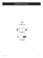
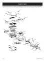
SBB2804-1 Gas Grill With Surround
Owner’s Manual
GAS-FIRED
Page 1
IMPORTANT
This manual should be read thoroughly by the person installing the grill and all persons who will use and
maintain the grill. The installer should be sure the manual is left in the possession of the user. The user
should retain this manual for future reference when using or cleaning the grill and to properly identify
any repair parts that may be required.
WARNING
Reference this manual for proper installation and maintenance instructions. Improper installation, adjustment, alteration, service or maintenance can cause personal injury or property damage. For assistance or additional information consult a qualified installer, service agency or the gas supplier.
CAUTION: FOR YOUR SAFETY
IF YOU SMELL GAS:
1.
2.
3.
4.
5.
Shut off gas to the appliance.
Extinguish any open flame.
Open the grill lid.
If odor continues, immediately call your gas supplier
or fire department.
Do not touch electrical switches.
CAUTION: FOR YOUR SAFETY
1. Do not store or use gasoline or other flammable vapors and liquids in the vicinity of this or any other
appliance.
2. An LP cylinder not connected for use shall not be stored in the vicinity of this or any other appliance.
CAUTION:
Parts may have sharp edges. Wear leather work gloves and handle parts carefully during the unpacking,
assembly and installation.
WARNING
Superb by Broilmaster® Gas Grills must ONLY use propane cylinders equipped with an Overfill Protection Device (OPD). Use only a reputable propane dealer when exchanging or filling cylinders. An overfilled or improperly filled propane cylinder can be dangerous.
Page 2
SBB00104-2-0808
Congratulations!
Welcome to the beauty and durability of a Superb by Broilmaster®
Gas Grill.
At Broilmaster, we continually strive to enhance the performance
and quality of our products for your grilling enjoyment. Every effort will be made to ensure that Broilmaster continues to be your
choice as the grill of the future.
Whether you are at the lake or in the privacy of your own backyard, the Superb by Broilmaster® Gas Grill performs far beyond
the ordinary and is designed to provide your family with years of
outdoor cooking pleasure.
Thank You!
Broilmaster® is a registered trademark of
Empire Comfort Systems, Inc.
918 Freeburg Ave.
Belleville, Illinois 62220
Telephone 800-851-3153
SBB00104-2-0808
Page 3
TABLE OF CONTENTS
Congratulations!
You have chosen the finest grill for your outdoor cooking pleasure. Please take time to read this entire manual before assembling your
Superb by Broilmaster® Gas Grill.
SECTION
PAGE
Hardware Package ........................................................................................................................................ 5
Parts View ..................................................................................................................................................... 6
Parts List ....................................................................................................................................................... 7
Grill Assembly .............................................................................................................................................. 8
Surround Location, Connections, and Safety ............................................................................................... 9
Enclosure Construction Guidelines ..............................................................................................................10
Surround Assembly ......................................................................................................................................11
Surround and Grill Assembly .......................................................................................................................12
Rotisserie Installation .................................................................................................................................. 13
Alternate Match Lighting ............................................................................................................................ 14
Rotisserie Operation .................................................................................................................................... 15
Propane Gas Grills .............................................................................................................................. 16 - 17
Gas Conversion to Natural Gas ................................................................................................................... 18
Operation ............................................................................................................................................. 19 - 20
Maintenance ................................................................................................................................................ 21
Troubleshooting .......................................................................................................................................... 22
Warranty Terms ........................................................................................................................................... 23
Your Superb by Broilmaster® Gas Grill is identified by model number, serial number, and gas
type. This information is provided on a product identification label located on the rear panel of
grill. For your convenience, complete this section for future reference when contacting your
dealer.
Model No.
Dealer
Serial No.
Dealer Phone No.
Gas Type: Propane
Page 4
Natural
Date of Purchase
SBB00104-2-0808
HARDWARE PACKAGE
SBB00104-2-0808
Page 5
PARTS VIEW
All repair part orders should be placed through your local Broilmaster® dealer. To locate a dealer in your area, contact Broilmaster Customer Service at 800-851-3153 or www.broilmaster.com. To ensure prompt and accurate service, please provide the following information when placing a repair part order: Model Number, Serial Number, Part Name, Part Number, and Quantity of parts needed.
1
2
3
3
4
10
12
5
7
13
8
6
11
9
14
15
16
17
18
19
22
20
21
23
23
24
25
26
27
27
29
26
34
35
28
31
32
30
32
33
Page 6
33
SBB00104-2-0808
PARTS LIST
INDEX NO.
PART NUMBER
1
SBB00014
THERMOMETER
2
SBB00108
LID
3
SBB00013
NUT AND LID BOLT
4
SBB00078
WARMING RACK
5
SBB00064
ROTISSERIE MOTOR
6
SBB00065
ROTISSERIE MOTOR BRACKET
7
SBB00067
ROTISSERIE ROD
8
SBB00068
ROTISSERIE FORKS
9
SBB00069
ROTISSERIE ROD BUSHING & SCREW
10
SBB00092
JAMB NUT
11
SBB00071
ROTISSERIE COUNTERBALANCE
12
SBB00070
ROTISSERIE ROD HANDLE
13
SBB00109
COOKING GRATE
14
SBB00102
FLAME TAMER
15
SBB00106
FLAME CARRYOVER
16
SBB00051
MAIN BURNER
17
SBB00110
ROTISSERIE BURNER BACK COVER
18
SBB00073
ROTISSERIE ORIFICE LP
18
SBB00075
ROTISSERIE ORIFICE NAT
19
SBB00062
ROTISSERIE BURNER
20
SBB00060
ROTISSERIE ELECTRODE
21
SBB00059
ROTISSERIE THERMOCOUPLE
22
SBB00111
ROTISSERIE THERMOCOUPLE SHIELD
23
SBB00050
MAIN BURNER ELECTRODE
24
SBB00091
RADIATION SHIELD
25
SBB00038
ROTISSERIE VALVE
26
SBB00037
MAIN BURNER VALVE
27
SBB00030
MAIN BURNER ORIFICE LP
27
SBB00031
MAIN BURNER ORIFICE NAT
28
SBB00041
MANIFOLD
29
B101205
FLEX LINE
30
SBB00049
IGNITOR
31
SBB00112
CONTROL PANEL
32
SBB00033
BEZELS
33
SBB00032
KNOBS
34
SBB00103
GREASE TRAY
35
SBB00107
SURROUND
SBB00104-2-0808
DESCRIPTION
Page 7
GRILL ASSEMBLY
Before You Begin
This grill requires some assembly and installation. Follow all
instructions.
If you purchased an accessory with your Superb by Broilmaster
Gas Grill, follow the instructions provided with the accessory for
assembly and installation. If an instruction refers to a step that is not
required for your grill model, please continue to the next step.
®
CAUTION: FOR YOUR SAFETY
Parts may have sharp edges. Wear leather work gloves and
handle parts carefully during the unpacking, assembly and
installation.
Page 8
Recommended Tools
These items are recommended for the assembly of your grill:
•
•
Phillips screwdriver
Soapy water solution (to test for leaks)
Grill Mountings
Refer to the instructions provided with each accessory for assembly, installation, and mounting procedures.
Gas Consumption on Grill Burners
Each Main Burner
HI
LO
Rotisserie Burner
Optional Side Burner
HI
LO
12,000 BTU/Hr
6,500 BTU/Hr
12,000 BTU/Hr
13,000 BTU/Hr
5,750 BTU/Hr
SBB00104-2-0808
SURROUND LOCATION, CONNECTIONS, AND SAFETY
Surround Kit Location
Built-In Kits are designed for outdoor use ONLY.
This Built-In Kit is designed for use with SBB2804 Broilmaster®
gas grills and cannot be used with any other grill or in any other
capacity.
Never install or operate your Built-In Kit in any building, garage,
or other enclosed area.
For your safety, the Built-In Kit should not be installed or operated
under any combustible materials, such as carports, covered
porches, awnings, or overhangs.
Never install or use your Built-In Kit in or on any recreational
vehicle or boat.
CAUTION: THE INSTALLATION AND OPERATION
OF THIS BUILT-IN KIT AT CLEARANCES LESS THAN
SPECIFIED BELOW MAY LEAD TO THE POSSIBILITY
OF FIRE, PROPERTY DAMAGE, OR PERSONAL
INJURY.
A minimum clearance of twenty-four (24”) inches is required
from all sides of the island to any combustible material.
Examples of combustible materials are patio furniture, fences, or
the outside of your home.
The area surrounding the built-in kit should be clear to ensure
proper ventilation. Do not obstruct the flow of combustion
and ventilation air in any way. The ventilation openings on the
enclosure must also remain free and clear of debris.
WARNING: DO NOT INSTALL OR OPERATE THIS BUILTIN KIT WHERE GASOLINE OR OTHER FLAMMABLE
MATERIALS ARE USED OR STORED. FAILURE TO
COMPLY WITH THIS WARNING COULD RESULT IN
EXPLOSION OR FIRE CAUSING PROPERTY DAMAGE
OR PERSONAL INJURY.
CAUTION: THE GRILL AND ITS INDIVIDUAL SHUTOFF
VALVE MUST BE DISCONNECTED FROM THE GAS
SUPPLY PIPING SYSTEM DURING ANY SYSTEM
PRESSURE TESTING AT TEST PRESSURES IN EXCESS
OF 1/2 PSIG.
Checking for Gas Leaks
CAUTION: DO NOT USE AN OPEN FLAME TO CHECK
FOR LEAKS. CHECKING FOR LEAKS WITH AN
OPEN FLAME MAY LEAD TO A FIRE OR EXPLOSION,
RESULTING IN PROPERTY DAMAGE OR PERSONAL
INJURY.
Using the following steps, check for gas leaks during initial
use and each time your Broilmaster® gas grill or side burner is
connected to gas or is connected to a cylinder that has not been
used recently
1.
Using dish washing detergent and water, make a soapy
solution.
2.
Turn OFF the knob on both the grill and side burner’s control
panel.
3.
Turn ON the gas at the supply. A hissing sound indicates a
leak. Turn OFF the gas and repair all leaks.
4.
If no hissing occurs, apply the soapy solution to all gas
connections.
5.
Look for bubbles. Bubbles indicate a leak.
6.
If there are bubbles, turn OFF the gas and repair all leaks.
7.
Turn the gas ON and repeat the above procedure until all
leaks are repaired.
Connection Requirements
CAUTION: NEVER USE LIQUID PROPANE GAS IN A
GRILL DESIGNED FOR NATURAL GAS, OR NATURAL
GAS IN A GRILL DESIGNED FOR LIQUID PROPANE
GAS. QUESTIONS REGARDING DIFFERENT TYPES OF
GASES SHOULD BE DIRECTED TO YOUR LOCAL GAS
COMPANY.
Installation must conform to local codes or, in the absence of
local codes, with the National Fuel Gas Code, ANSI Z223.1.
In Canada, installation shall be in accordance with CAN/CGAB149.2 Propane Installation Code, or CAN/CGA-B149.1 Natural
Gas Installation Code, and local codes where applicable. Consult
your local gas company or Propane gas dealer for code regulations
and recommended procedures.
Broilmaster® gas grills and side burners are NOT equipped with
pressure regulators. Your NAT gas grill operates at a manifold
pressure of seven (7”) inches water column.
SBB00104-2-0808
Page 9
ENCLOSURE CONSTRUCTION GUIDELINES
Enclosure must be construction from non-combustible material.
If tile is used on the top surface of your enclosure, it may be necessary to enlarge openings at the top edges to allow the frame pieces of
the SBB and BSA to mount flush against the enclosure.
Screws for enclosure mounting have not been supplied. Installer must measure for thickness and purchase and use appropriate hardware
for installation. If the enclosure is constructed from masonry materials, it may be necessary to substitute appropriate screws and
fasteners.
This diagram is only a basic plan for constructing an enclosure for your built-in kit. All construction and installation should comply with
all local building codes and requirements. Drawing is not to scale.
Key
A
B
C
D
E
F
G
H
J
K
L
M
N
Page 10
Dimension in Inches
38” (Minimum)
16” (Minimum)
28” (Minimum)
27 7/8”
9 9/32”
12 3/16”
6” (Minimum)
22 1/2”
10 27/32”
19 13/16”
2 1/2”
5 1/32”
22 3/8” (Single) - 15 5/8” (Double)
MINIMUM REQUIREMENTS
Key Dimension in Inches
O
14” (Single) - 27 1/2” (Double)
P
15 7/16” (Single) - 8 11/16” (Double)
Q
13 15/16”
R
5” (Minimum)
S
24 13/16”
T
24 3/4”
U
10”
V
2 1/4”
W
2 3/4”
X
9”
Y
1 13/16”
Z
14 3/8”
SBB00104-2-0808
SURROUND ASSEMBLY
1.
The grill is shipped with the surround and the grill head attached by four screws as shown in the drawing below. Please
remove the four screws to seperate the surround from the grill
head. See Figure 1.
3.
Secure the SBB surround to the enclosure using up to
eight screws (not provided). See Figure 3.
Note: If you have a masonry structure you may need to
substitute for the appropriate masonry fasteners.
Figure 3
Figure 1
2.
Place the SBB surround into position in the constructed
enclosure. See Figure 2.
Figure 2
SBB00104-2-0808
Page 11
SURROUND AND GRILL ASSEMBLY
4.
Slide grill head with flex gas line attached into surround. Make
sure flex gas line is protruding out surround side. See Figures
4 and 5.
Figure 6
Figure 4
6.
7.
8.
Figure 5
5.
Attach grill head to surround from inside of the grill
with four (4) lock washers, and 1/2” screws (provided).
See Figure 6.
Place flame tamers over burners. Pins on burner box fit through
holes on flame tamer. See Figure 7.
Place cooking grids into grill. See Figure 7.
Place warming rack on top of grill body side walls.
See Figure 7.
Figure 7
9.
Remove ignitor button, insert AA battery (provided) positive
side facing out, replace ignitor button. See Figure 8.
Figure 8
Page 12
SBB00104-2-0808
ROTISSERIE INSTALLATION
The Infrared burner (Rotisserie burner) is for rotisserie cooking
only. Warning: Never use the main burners while using the
Infrared Back Burner, as this could result in igniting the drippings, or overheating your grill. Remove warming rack and
cooking grids.
10. Remove all components from the carton. See Figure 9.
13. Slide a rotisserie fork onto each end of the spit. See Figure
12.
14. Adjust spacing between rotisserie forks to accommodate your
food. Tighten the thumbscrews to secure the holding forks.
15. Slide the bushing onto threaded end of spit. Insert spit into
slot of motor on left side of grill and place bushing into slot
on right side of grill. Tighten thumbscrew on bushing.
See Figure 12.
Figure 9
11. Attach the motor bracket to the left side of the grill with two
(2) lock washers, and 1/4” screws. See Figure 10.
Figure 12
16. Screw jamb nut to the threaded side of spit. Slide counterbalance onto threaded end of spit. The counterbalance will remain
to the outside of the grill. Screw second jamb nut into the spit
to hold counterbalance in place. See Figure 13.
17. Attach handle onto spit. See Figure 13.
Figure 10
12. Slide motor into position on motor bracket. See Figure 11.
Figure 13
Figure 11
SBB00104-2-0808
Page 13
ALTERNATE MATCH LIGHTING
1.
2.
3.
4.
5.
6.
7.
8.
9.
Turn the burner control knobs clockwise to the OFF
position.
Turn ON gas at the source.
Open the grill lid.
Locate the Ignitor Rod, which is permanently attached to the
inside of the right surround side.
Insert an unlit match into the coiled end of the ignitor rod.
Light the match.
Insert the ignitor rod through the right hole located on the
flame tamers of the grill. Position the match near the front
corner of the burner. See Figure 14.
Turn the left burner control knob counterclockwise to HI.
If the burner fails to light after 5 seconds, turn the burner control
knob OFF for five minutes then repeat the procedure.
If the burner continues not to light, turn OFF all gas and refer
to the troubleshooting section of your grill Owner’s Manual.
Figure 14
Page 14
SBB00104-2-0808
ROTISSERIE OPERATION
Using the Ignitor
Caution: If burner fails to light after 5 seconds, turn the burner
OFF for 5 minutes, to allow the gas to clear, then try again.
Attention: You must use the control knob that is second from the
left side of grill to ignite the rotisserie.
1.
2.
3.
4.
Turn the control knob clockwise
to the OFF position.
Turn ON gas supply to grill.
With the grill lid open, push and turn the rotisserie control
knob counterclockwise
to ON.
Push and hold the ignitor button until the rotisserie burner
ignites.
Attention: When igniting the rotisserie burner, hold rotisserie
control knob in for 30 seconds in order to energize the thermocouple.
5.
If rotisserie burner does not ignite, turn rotisserie control knob
clockwise
to the OFF position. Turn OFF gas supply
to grill. Refer to Troubleshooting section in this manual.
Before rotisserie cooking you will need to remove the warming rack
and the Cooking Grids from your grill. When Rotisserie Cooking
you can place a Cooking pan under the food to be cooked. This will
capture the drippings and keep your grill clean of excess grease
which could cause a fire. Use caution when moving a cooking pan
containing hot oils.
Rotisserie Use
Warning: Do not operate the side burner option simultaneously with the rotisserie. The side burner will melt the rotisserie
handle.
Secure meat firmly to the spit rod with meat holders (It may be
necessary to tie fowl and rolled roasts to retain their shape for even
rotation). To ensure proper rotation, it is important to adequately
balance and fasten the meat or fowl onto the spit rod.
Before heating the grill, rotate the spit rod and meat manually a
few times. If out of balance, attach the counterbalance assembly
to the spit to even out the weight and rotate again.
During cooking, adjust the meat holders if the meat shrinks and
pulls away from the spit rod. Use gloves and caution to prevent
burns.
Be certain that the rotisserie brackets and motor are secured in place,
then light the burner and close the grill lid for preheating.
After preheating, place the loaded spit rod into position. Start the
rotisserie motor and make certain the food is properly balanced.
Close the grill lid.
Note: Beef and pork roasts and certain types of fowl will release
a considerable amount of fat and juice in the process of cooking
and are therefore “self-basting.” Lean meat and chicken will taste
better if basted occasionally with melted butter, margarine, salad
oil, barbeque sauce or a sauce of your own preference.
The Rotisserie Motor is rated to turn a maximum load of
12 pounds.
The exact degree of “doneness” can be determined by the use of
a meat thermometer.
Warnings:
ROTISSERIE COUNTERBALANCE
Never use the Rotisserie Motor in the rain, and never use it if it
has become wet.
Always use a grounded three-prong outlet and a three-prong extension cord to energize the Rotisserie Motor.
Never alter or remove the grounding prong on the Rotisserie Power
Cord, as an electric shock hazard would then result.
Never permit an electrical supply cord or gas supply line to
contact any heated surface of this grill.
WARNING
The Rotisserie Motor must be electrically grounded in accordance
with local codes or, in the absence of local codes, with the National
Electric Code, ANSI/NFPA 70. Keep the Rotisserie Motor electric
cord away from the heated surface of the grill. Do not operate the
Rotisserie with a damaged cord or plug, or if the Rotisserie malfunctions or has been damaged in any manner. Call the Customer Service
for replacement. The power supply cord has a 3-prong grounded
plug. For your personal safety do not remove the grounding prong.
It must be plugged into a mating 3-prong grounding type receptacle,
grounded in accordance with the National Electrical Codes and local codes and ordinances. If an extension cord is used, it must be
properly grounded and suitable for use with Outdoor Appliances.
Keep the extension cord connection dry, off of the ground and out
of the reach of children. When the Rotisserie Motor is not in use,
remove and store in a dry area.
SBB00104-2-0808
Figure 15
SCREW JAMB NUTS ONTO ROD UNTIL SNUG AGAINST
COUNTERBALANCE. COUNTERBALANCE CAN BE
ADJUSTED VERTICALLY FOR BEST WEIGHT DISTRIBUTION.
Page 15
PROPANE GAS GRILLS
Grill Location
4.
When choosing the ideal location for your Superb by Broilmaster
Gas Grill, remember this grill is designed for outdoor use ONLY.
®
You should never install or operate your grill in any building,
garage, or other enclosed area.
For your safety, this grill should not be installed or operated under
any combustible materials, such as carports, covered porches,
awnings, or overhangs.
Never install or operate your grill in or on any recreational vehicle
or boat.
CAUTION: The installation and operation of this grill at
clearances less than specified below may lead to the possibility
of fire, property damage, or personal injury.
Some examples of combustible materials are a wall, a fence, patio
furniture, or the wall of your home.
The area surrounding the grill should be clear to ensure proper
ventilation. Do not obstruct the flow of combustion and ventilation
air in any way. The ventilation openings on the propane cylinder
enclosure must also remain free and clear of debris.
Portable grills should be level and positioned away from direct
wind prior to each use.
WARNING: Do not install or operate this grill where gasoline or other flammable materials are used or stored. Failure
to comply with this warning could result in explosion or fire
causing property damage or personal injury.
Gas Type
Never use Liquid Propane (LP) gas with a grill designed for Natural
gas, or Natural gas with a grill designed for Liquid Propane gas.
The type of gas required for your grill can be determined from the
product identification label located on the grill’s right side panel
of the cart. Questions regarding different types of gases should be
directed to your gas supplier.
Cylinder Requirements
Your Superb by Broilmaster Gas Grill requires a standard twenty
(20) pound propane gas cylinder.
®
The maximum height allowable for a replacement cylinder is approximately twelve (12”) inches (30.5 centimeters).
The propane gas cylinder must be:
1. Constructed and marked in accordance with the specifications
for LP gas cylinder of the U.S. Department of Transportation
(D.O.T.) or the National Standard of Canada, CAN/CSA-B339,
Cylinders, Spheres, and Tubes for Transportation of Dangerous
Goods; and Commission as applicable.
2. Provided with a listed overfilling protection device (OPD).
3. Provided with a listed safety device having direct access with
the vapor space of the cylinder and the cylinder supply system
must be arranged for vapor removal.
Page 16
5.
6.
Provided with a shutoff valve terminating in a valve outlet as
specified in the Standard for Compressed Gas Cylinder Outlet
and Inlet Connections, ANSI CGA-V-1.
Provided with a plug to effectively seal off the cylinder outlet
when the cylinder is being stored or transported.
Provided with a collar to protect the cylinder valve.
Caution: Do not use a propane gas cylinder which has a capacity greater than twenty (20) pounds with this grill and side
burner.
Propane Cylinder Safety
Liquid Propane (LP has a long history of safe use when the safety
precautions provided in this manual are followed.
Failure to follow these safety precautions could result in a fire
or explosion causing property damage or personal injury.
Propane gas cylinders should always be handled, stored, and transported with extreme caution in a secured upright position.
Never attempt to use or repair a propane gas cylinder that has been
damaged. Never attempt to use or repair a cylinder with a faulty or
damaged valve outlet. A cylinder that has been dropped, dented, or
otherwise damaged must be replaced.
A propane gas cylinder should never be transported in the passenger
area of a vehicle.
Keep cylinders out of direct sunlight and never apply any other
source of direct heat to them.
When refilling your cylinder, always insist on a reputable, qualified gas dealer. Your propane gas cylinder is filled by weight, and
should never exceed eighty (80%) percent of its weight limit. If
the cylinder is not completely empty, the gas dealer must make
necessary adjustments to ensure it is not overfilled. Never use an
overfilled Propane gas cylinder.
Cylinder Storage
Your grill must be stored outdoors in a well ventilated area if the
cylinder is attached to it.
Disconnected cylinders must have a threaded valve plug tightly
installed and must not be stored in any building, garage, or other
enclosed area.
Flammable materials (gasoline, grill covers, etc.) must not be stored
in the cylinder enclosure.
Always store Propane cylinders in a secured upright position, out
of reach of children.
Connection Requirements
Caution: Never use Liquid Propane (LP) gas in a grill designed
for Natural gas, or Natural gas in a grill designed for Liquid
Propane gas. Questions regarding different types of gases
should be directed to your local gas supplier.
SBB00104-2-0808
PROPANE GAS GRILLS (cont.)
Installation must conform to local codes or, in the absence of local
codes, with the National Fuel Gas Code, ANSI Z223.1. In Canada,
installation shall be in accordance with CAN/CGA-B149.2 Propane
Installation Code, or CAN/CGA-B149.1 Natural Gas Installation
Code, and local codes where applicable. Consult your local gas
supplier or propane gas dealer for code regulations and recommended procedures.
Warning: Superb by Broilmaster® Gas Grills require Liquid
Propane (LP) cylinders equipped with an Overfill Protection
Device (OPD). An overfilled or improperly filled Propane
cylinder can be dangerous.
Always use the pressure regulator and hose assembly supplied with
your Propane gas grill.
Note: Not all valve and cylinder combinations are compatible.
Check warning tag on valve and cylinder as well as external
fitting threads.
All Broilmaster pressure regulators and hose assemblies require
Propane cylinders with a Type 1 connection device as illustrated.
See Figure 17.
Figure 16
Attach the pressure regulator to the Propane gas cylinder’s valve
using the plastic handwheel. Tighten in a clockwise motion to
achieve a gas tight seal. See Figure 17.
Pressure Regulator and Hose Assembly
The pressure regulator has an outlet pressure of not more than
eleven (11”) inches water column. It must be connected to the
Propane gas cylinder’s female valve outlet before the grill can be
operated.
Caution: Operation of a propane gas grill without the
pressure regulator and hose assembly will cause gas leaks which
could lead to fire or explosion, resulting in property damage
or personal injury.
Figure 17
Caution: Do not use a wrench or any other tool to tighten. Use
of a wrench or other tool will damage the plastic handwheel.
The pressure regulator’s fitting must remain clean and free of
nicks and scratches. A dirty, nicked or scratched fitting can cause
a gas leak, resulting in an explosion or fire. Use only genuine
Broilmaster® replacement parts unless otherwise specified by the
manufacturer.
Connecting to Propane Gas / Cylinder Retention Means
Attention: Propane gas cylinders that are acceptable for use with
this grill must comply with “Cylinder Requirements” section and
“Connection Requirements” section (Pages 16 - 17.)
Open caddy door. Position the cylinder in the opening at the bottom
of the caddy. See Figure 16.
If you are using natural gas or a fixed fuel propane gas supply
a 3/8 NPT flare is provided for LP tank. Check for gas leaks as
discussed in the “Checking for Gas Leaks” Section of this manual
on page 9.
Figure 18
To disconnect the Propane gas cylinder, turn OFF the cylinder’s
valve and the grill’s control valve. Remove the regulator by turning
the plastic handwheel counterclockwise.
SBB00104-2-0808
Page 17
GAS CONVERSION TO NATURAL GAS
A conversion kit to natural gas is included with your grill.
1.
2.
3.
4.
5.
6.
7.
8.
9.
10.
11.
12.
13.
14.
Remove cooking grids and flame tamer from grill.
Use allen wrench supplied in conversion kit to remove control
knobs.
Remove control panel (4 Phillips screws).
Figure 19
Use a 7mm socket or wrench to remove all LP gas orifices
marked 1.02 from gas valves.
Install natural gas orifices marked 1.51 into gas valves. Apply
pipe compound to threads on orifices prior to installation.
Attach left side of control panel to grill with two (2) Phillips
screws from Step 3. Carefully insert left burner orifice into left
burner. Continue to carefully insert the remaining orifices into
the burners. Attach right side of control panel to grill with two
(2) Phillips screws from Step 3.
The low input adjustment screws are located inside the main
burner valve stems. Use small screwdriver supplied in conversion kit to turn each adjustment screw clockwise 1/4 turn (90
degrees).
The valve stem that is second from the left side of the grill is
the rotisserie valve stem and it will not be adjusted.
Remove rotisserie burner back cover (5 Phillips screws - four
on the back and one on inside top of the back of the grill).
Use a 14mm wrench or adjustable wrench to remove LP gas
rotisserie orifice marked 1.02 from orifice fitting.
Install natural gas rotisserie orifice marked 1.51 into orifice
fitting. Apply pipe compound to threads on orifice prior to
installation.
Remove the hose and regulator from the gas connection on
grill with an adjustable wrench.
Connect the grill to the natural gas supply.
Attention: Before lighting your grill check all gas connections
including the adjustment screws in valve stems for gas leaks
with a soapy water mixture.
Caution: Do not use the grill if a gas leak is detected until gas
leak is corrected. If a gas leak can not be stopped, do not use
grill. You must contact a qualified repair person.
Replace back panel (5 Phillips screws from step 8).
Page 18
15. Replace all control knobs with allen wrench.
16. Apply the completed conversion label adjacent to the rating
plate label on the rear panel of the grill.
17. The natural gas inlet pressure at the grill is to be set at 7.0” of
inlet pressure.
18. Ignite burners on grill and observe flame pattern. If flame is
yellow in color or flame is lifting off burner, the air shutter on
burners will require adjustment.
19. Turn OFF (but do NOT remove) natural gas supply to grill.
20. Loosen (but do NOT remove) two (2) Phillips screws at end
of each burner. Lift upward and pivot burner out of grill.
21. Loosen Phillips screw at air shutter. Air shutter for natural gas
should have about 1/4” opening. Open air shutter for a yellow
flame or close air shutter for a lifting flame. Tighten Phillips
screw at air shutter.
22. Replace burners into grill. Tighten two (2) Phillips screws at
end of each burner.
23. Ignite burners on grill to verify burner flame characteristics.
Installation must conform to local codes or, in the absence of local
codes, with the National Fuel Gas Code, ANSI Z223.1. In Canada,
installation shall be in accordance with CAN/CGA-B149.1 Natural
Gas Installation Code, and local codes where applicable. Contact
your local gas company for code regulations, recommended procedures, and the installation of your grill’s gas supply line.
Caution: The grill and its individual shutoff valve must be disconnected from the gas supply piping system during any system
pressure testing at test pressures in excess of 1/2 PSIG.
Caution: The grill must be isolated from the gas supply piping
system by closing its individual manual shutoff valve during
any pressure testing of the gas supply piping system at test
pressures equal to or less than 1/2 PSIG.
SBB00104-2-0808
OPERATION
Checking for Gas Leaks
Check for gas leaks every time you connect your Superb by
Broilmaster® propane gas grill to a Propane gas cylinder, when a
connected cylinder has not been used recently, or when either a
natural or propane grill is being used for the first time.
OPERATING INSTRUCTIONS
Using Matches
Caution: Do not use a flame when checking for leaks. Checking
for leaks with a flame may lead to a fire or explosion, resulting
in property damage or personal injury.
Attention: You must use the control knob on the right side of the
grill to ignite the first burner. The second burner to be ignited will
be the second from right side of grill and so forth, always moving
from right to left.
To check for gas leaks:
1. Use dish washing liquid and a little water to make a soapy
solution.
2. Turn OFF the knobs on the control panel.
3. Turn ON the gas at the supply or cylinder. A hissing sound
indicates a leak. Turn OFF the gas and repair the leak.
4. Apply the soapy water solution to all gas connections.
5. Look for bubbles. Bubbles indicate a leak.
6. If there are bubbles turn OFF the gas and repair the leak.
7. Turn the gas back ON and repeat the above procedures until
all leaks are repaired.
Caution: If a burner fails to light after 5 seconds, turn the
burner OFF for 5 minutes, to allow the gas to clear, then try
again.
Attention: The control knob that is second from left side of grill is
for the rotisserie. See Rotisserie Operation on page 15.
1. Turn the right control knob clockwise
to the OFF
position.
2. Turn ON gas supply to the grill.
3. Open the grill lid.
4. A match holder is attached to the inside of the right surround
side. Place a match into match holder. Insert burning match
through the front right hole of the flame tamer of the grill.
Place burning match adjacent to right burner.
Air Shutter Adjustment
1. Remove cooking grids and flame tamers from grill.
2. Ignite burners on grill and observe flame pattern. If flame is
yellow in color or flame is lifting off burner the air shutter on
burner will require adjustment.
3. Turn gas OFF and allow the grill to cool.
4. Loosen two (2) Phillips screws at end of each burner. Lift
upward and pivot burner out of grill.
5. Loosen Phillips screw at air shutter. Open air shutter for a
yellow flame or close air shutter for a lifting flame. Tighten
Phillips screw at air shutter.
6. Replace burners into grill. Tighten two (2) Phillips screws at
end of each burner.
7. Ignite burners on grill to verify burner flame characteristics.
OPERATING INSTRUCTIONS
Using the Ignitor
Caution: If a burner fails to light after 5 seconds, turn the
burner OFF for 5 minutes, to allow the gas to clear, then try
again.
Attention: You should use the center burner(s) to ignite the first
burner, then move from center to both sides.
Attention: The control knob that is second from left side of grill
is for the rotisserie. See Rotisserie Operation on page 15.
5.
1.
6.
2.
3.
4.
5.
Turn the right control knob clockwise
to the OFF
position.
Turn ON gas supply to the grill.
With the grill lid open, push and turn the right control knob
counterclockwise
to HI.
Push and hold in the ignitor button until the right burner ignites.
If right burner does not ignite, turn right control knob clockwise
to the OFF position. Turn OFF gas supply to grill.
Refer to Troubleshooting section in this manual.
SBB00104-2-0808
Figure 20
Push and turn the right control knob counterclockwise
to HI.
If right burner does not ignite, turn right control knob clockwise
to the OFF position. Turn OFF gas supply to grill.
Refer to Troubleshooting section in this manual.
Page 19
OPERATION (cont.)
Before Cooking
Before cooking on a grill for the first time, it should be “burned off”
to remove any oil residue from the manufacturing process.
1.
2.
3.
4.
5.
Raise the grill lid.
Light grill burners.
Burn on HI for ten minutes.
Close the lid and burn on HI for an additional ten minutes.
Turn OFF gas. The grill is now ready for use.
Preheating
Before cooking on a gas grill, allow the grill to preheat on HI for
5 minutes with the lid closed.
This uses very little fuel and provides better flavor.
Electrical Accessories
If an electrical accessory (e.g. rotisserie) is used on your grill, the
accessory must be electrically grounded in accordance with local
codes, or in the absence of local codes, with the National Electric
Code, ANSI/NFPA 70. In Canada, the electrical accessory must be
electrically grounded in accordance with the applicable section of
the current Canadian Electrical Code, CSA C22.1.
Any electrical accessory should be equipped with a three-prong
(grounding) plug, and plugged into a properly grounded threeprong receptacle or wall outlet. Do not cut or remove the grounding
prong from the plug.
If an extension cord is required, use only a three-prong cord and
plug into a properly grounded receptacle as described above.
Do not expose an electrical accessory to water. Avoid using any
electrical accessory in wet weather as it may present a shock
hazard.
Keep any electrical cord and fuel supply hose away from all heated
surfaces.
Page 20
SBB00104-2-0808
MAINTENANCE
Cleaning the Grill
Caution: To prevent injury, do not clean a hot grill.
Note: Do not use a commercial cleaner on the cooking grids. Do
not brush grids while they are hot. Do not scrape grids.
For baked on residue use a BRASS (NOT STEEL) brush on the
cooking grids and other components.
Burn Off
This process is much like that used in self-cleaning ovens and is
most efficient when completed after each use of the grill.
Caution: Do not open the grill during the burn off process.
Opening the grill during the burn off process may cause a sudden grease fire flare up that could burn your face and arms.
Wait until the grill has cooled before opening.
1.
2.
3.
Turn control knobs to HI. Close lid and allow the grill to burn
for ten minutes, or until no smoke is present. Do not allow the
grill to burn for more than 30 minutes.
Turn control knobs and gas supply to OFF and allow the grill
to cool.
Wipe COOL grill with a damp cloth to remove soot.
Grill Bottom
Periodically remove cooking grids and flame tamers to clean the
interior of the grill. Scrape off baked on residue with a putty knife
or brass brush and rinse with water. Clean the bottom air holes
with a small knife.
Grease Tray
Empty periodically.
Exterior
Clean regularly with a solution of mild detergent and hot water.
Superb by Broilmaster® protective covers are recommended. Stainless steel components can be easily cleaned with a spray-on stainless
steel cleaner found in most hardware stores.
Venturi Tubes
The venturi tubes allow air and gas to mix prior to burning, thus
ensuring an efficient flame. Spiders or other small insects may
build webs or nests inside the tubes obstructing air flow. Fire, or
flashback, can occur, in and/or around obstructed venturi tubes and
can cause damage to components beneath the grill or an unsafe
condition. TO reduce risk, inspections and cleaning should be
performed at least twice monthly when spiders are active. If the
grill has been unused for an extended period of time inspect the
tubes before using the grill.
Clean Rotisserie burner and venturi tubes as follows:
1. Remove rotisserie burner back cover (5 Phillips screws - 4 on
the back and 1 on the inside top).
2. Use a small flexible brush to remove any debris from the
venturi tubes (interior of burners).
3. Replace rotisserie burner back cover.
Burner Maintenance
Stainless steel burners often turn reddish brown after use. This does
not effect the performance of the grill. When cleaning the interior
of the grill, remove the burners and clean with a brass brush. Wash
with water and a mild detergent.
Electrode Position
Igniter electrode tips need to be placed about 1/8” from the burner
surface in order to work properly. Adjust accordingly if it is misaligned. See Figure 21.
BURNER
1/8”
IGNITOR
Figure 21
SBB00104-2-0808
Page 21
TROUBLESHOOTING
Although the manufacturer has attempted to ensure that your grill will operate properly and satisfactorily, sometimes problems do
arise. The following troubleshooting guide lists several possible problems and their probable cause and solution.
Problem
Burner will not light.
Cause
Gas injector not inserted in venturi tube.
Clogged gas injector.
Obstruction in gas line.
Spider webs in venturi tubes.
Misalignment of electrode.
Out of gas.
Inadequate grill temperature.
Flames blow out
Yellow flames.
Dead battery.
Poor combustion.
Misalignment of venturi tube and gas
injector.
Inadequate gas pressure.
Incorrect orifice/valve setting.
Cold grill.
Misalignment of burner tube and gas
injector.
Poor combustion.
Extreme wind.
Air shutter improperly set.
Spider webs in venturi tubes.
Seasoning salts on burner.
Oil film on burner.
Page 22
Solution
Realign/engage gas injector with the
venturi tube.
Remove gas injector from gas control assembly and clean.
For propane models, ensure gas valve on
cylinder is OFF. Remove flexible hose and
blow out any debris.
Clean venturi tubes. See Maintenance
Section on page 21
Position electrode properly.
Refill LP gas cylinder. If natural model,
turn on gas at source.
Replace with “AA” Alkaline battery.
Adjust air shutter.
Realign/engage gas injector with the
venturi tube.
Contact gas supplier for assistance.
Refer to gas conversion instructions in this
manual.
Preheat grill at least 5 minutes on HI with
the grill lid closed.
Realign/engage gas injector with the
burner tube.
Adjust air shutter.
Turn or shield grill.
Open air shutter.
Clean venturi tubes. See Maintenance
Section.
Clean by washing burner with mild detergent.
Allow burner to operate on HI for 10 to 15
minutes.
SBB00104-2-0808
WARRANTY TERMS
Limited Lifetime Warranty
5 Years Against Rust-Through
1 Year Against Rust-Through
•
SBB2804 Stainless Steel Grill Lid, Body, and Cooking grids, Stainless Steel Built-In Surround
•
•
•
•
Stainless steel burners
Infrared rotisserie burners
Stainless steel warming rack
Stainless steel flame tamer
•
All other parts not listed above
What Is Covered And For How Long
From the date this Superb by Broilmaster Gas Grill is first purchased, we will make available at our factory a free replacement for any
defective part covered by this warranty on the following basis. Proof of purchase required. Warranty applies to original owner and is
not transferable.
What Is Not Covered
• Removal and reinstallation cost.
• Labor for replacement or repairs.
• The costs of a service call to diagnose a problem.
• Transportation and shipping cost.
• Surface corrosion.
• Discoloration of stainless steel – a normal result from exposure to heat and weather – is not covered under this warranty.
• Damage caused by dropping, scraping, or abrasive cleaning voids the warranty for all cooking grids.
• Chips in the paint and porcelain coatings are not covered under warranty. Regular maintenance and cleaning - including the
use of a grill cover – will help keep your grill looking great for years.
• Grills and finishes damaged by abrasive cleaning, improper installation, improper storage, accident, misuse, abuse, alteration,
commercial use, and unusually harsh environmental conditions. Harsh conditions could include, but are not limited to: continual
seawater spray, direct contact with pool chemicals or lawn chemicals, direct contact with corrosive materials.
• Inoperable due to improper or lack of cleaning.
This warranty does not imply or assume any responsibility for consequential damages that might result from misuse, or improper
installation of this cooking appliance.
This warranty covers only claims involving defective workmanship or materials.
A bill of sale, cancelled check, or payment record should be kept to verify purchase date and establish warranty period. Note: Empire
Comfort Systems is committed to continuous product improvement. Materials and specifications are subject to change without
notice.
SBB00104-2-0808
Page 23
THE MOST DURABLE GRILL
KNOWN TO MAN
BROILMASTER®
A Division of Empire Comfort Systems, Inc.
918 Freeburg Ave.
Belleville, Illinois 62220
Phone: 1-800-851-3153
FAX: 1-800-443-8648
VISIT OUR WEB SITE AT WWW.broilmaster.com
Page 24
SBB00104-2-0808