1
&RQWHQWV
1997 Andreas Stihl, Waiblingen
0458 343 3021
6
16
18
19
19
20
21
22
23
24
24
25
25
26
26
27
28
28
30
30
32
36
39
42
43
44
45
This manual contains warnings,
operating and safety precautions for the
STIHL FS 44 brushcutter.
Pay special attention to the safety precautions outlined on pages 6 to 15.
Allow only persons who understand this
Manual to operate your brushcutter.
To receive maximum performance and
satisfaction from your STIHL brushcutter, it is important that you read and
understand the maintenance and safety
precautions before using your brushcutter. Contact your STIHL dealer or the
STIHL distributor for your area if you do
not understand any of the instructions
in this Manual.
O
n
l
i
n
e
v
4
4
Fuel
Fueling
Fitting the Harness
Starting
- Version with Bike Handle
- Stop Switch on Throttle Trigger
Housing
- Stop Switch on Engine Housing
Motormanagement
Adjusting Carburetor
Checking Spark Plug
Cleaning Air Filter
Spark Arresting Screen
in Muffler
Gearbox Lubrication
Lubricating Flexible Shaft
Sharpening Cutting Tools
- Grass Cutting Blade 230-4
- Grass Cutting Blade 230-8
Operating Instructions
Storing the Machine
Maintenance Chart
Specifications
Special Accessories
Andreas Stihl Limited Warranty
Federal and California Emission
Control Systems Utility Engines
-n
o
t
f
o
r
r
Printed on chlorine-free paper
2
2
4
46
46
47
48
48
49
50
51
52
53
e
r
s
i
o
n
Parts and Controls
- Version with Bike Handle
- Version with "J" Handle
- Version with Loop Handle
- Version with Loop Handle and
Standoff Lever
- All Versions
Safety Precautions and
Working Techniques
Selecting the Cutting Tool
Mounting the Bike Handle
Mounting the "J"-Handle
Mounting Loop Handle with
Standoff Lever
Mounting the Loop Handle
- Version A
- Version B
Mounting the Deflector
Mounting the Cutting Tools
- STIHL Supercut 20-2
- STIHL Polycut 20-3
- STIHL Autocut 20-2
- STIHL Autocut 25-2
- STIHL Polymatic 30-2
- STIHL Autocut 24-2
- STIHL Fixed Line Head
- Grass Cutting Blade 230
54
:DUQLQJ
Because a brushcutter is a high-speed
cutting tool some special safety precautions must be observed to reduce
the risk of personal injury. Careless or
improper use may cause serious or
even fatal injury. Make sure your unit
is equipped with the proper deflector,
handle and harness for the type of
cutting attachment being used.
Always wear proper eye protection.
STIHL’s philosophy is to continually
improve all of its products. As a result,
engineering changes and improvements are made from time to time. If
the operating characteristics or the
appearance of your brushcutter differs
from those described in this Manual,
please contact your STIHL dealer for
information and assistance.
67,+
e
p
r
i
n
t
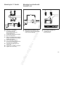
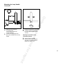
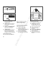
3DUWVDQG&RQWUROV
%LNH+DQGOH9HUVLRQ
13
2
3
7
1
5
9
4
8
343BA060 KN
12
11
10
e
r
s
i
o
n
1
6
3
15
8
10
14
11
2
5
-n
o
t
f
o
r
r
9
4
343BA061 KN
7
Bike handle
Throttle trigger
Throttle trigger interlock
Handle support
Clamp (Harness)
Starter grip
Spark plug boot
Carburetor adjusting screws
Fuel filler cap
Machine support
Throttle cable / stop switch wire
Throttle cable retainer
Slide control
O
n
l
i
n
e
v
6
1=
2=
3=
4=
5=
6=
7=
8=
9=
10 =
11 =
12 =
13 =
-+DQGOH9HUVLRQ
1=
2=
3=
4=
5=
6=
7=
8=
9=
10 =
11 =
"J"-handle
Throttle trigger
Throttle trigger interlock
Handle support
Clamp (Harness)
Starter grip
Spark plug boot
Carburetor adjusting screws
Fuel filler cap
Machine support
Throttle cable/stop switch wire
14 = Stop switch
15 = Handle hose
e
p
r
i
n
t
'HILQLWLRQV
%LNHKDQGOH
-KDQGOH
To hold the brushcutter with both
hands.
&DUEXUHWRUDGMXVWLQJVFUHZV
For tuning carburetor.
7KURWWOHWULJJHU
Controls the speed of the engine.
O
n
l
i
n
e
v
)XHOILOOHUFDS
For closing the fuel tank.
+DQGOHKRVH
For holding machine during starting
and cutting work.
0DFKLQHVXSSRUW
For resting machine on the ground.
7KURWWOHWULJJHULQWHUORFN
Must be depressed before the
throttle trigger can be activated.
7KURWWOHFDEOHVWRSVZLWFKZLUH
Connect operator’s control grip to
the powerhead.
+DQGOHVXSSRUW
Connects the drive shaft to the
handle bars.
&ODPS
The device to connect the brushcutter to the harness.
e
r
s
i
o
n
7KURWWOHFDEOHUHWDLQHU
Fixes the throttle cable on the drive
shaft.
6SDUNSOXJERRW
Connects the spark plug to the
ignition wire.
6WRSVZLWFK
Switches the engine’s ignition
system off and stops the engine.
-n
o
t
f
o
r
r
6WDUWHUJULS
The grip of the pull starter, which is
the device to start the engine.
6OLGHFRQWURO
Starting throttle lock and stop
switch. Keeps the throttle partially
open during starting and switches
the engine’s ignition off and stops
the engine.
e
p
r
i
n
t
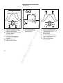
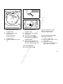
9HUVLRQVZLWKORRSKDQGOHDQGORRS
KDQGOHZLWKVWDQGRIIOHYHU
6
5
1
4
13
3
2
11
7
10
12
343BA059 K
9
e
r
s
i
o
n
16
14
-n
o
t
f
o
r
r
15
17
20
Loop handle
Standoff lever
Stop switch 1)
Throttle trigger interlock 2)
Starter grip
Spark plug boot
Carburetor adjusting screws
Fuel filler cap
Machine support
Throttle cable
Handle hose
Throttle trigger
Clamp (Harness) 2)
O
n
l
i
n
e
v
3
8
1=
2=
3=
4=
5=
6=
7=
8=
9=
10 =
11 =
12 =
13 =
18
19
$OOYHUVLRQV
14 = Fuel pump
15 = Air filter cover / choke
16 = Muffler
17 = Deflector
(version for all cutting tools)
18 = Skirt
19 = Line limiting blade
20 = Cutting tool
(STIHL "Supercut 20-1")
1)
Position varies according to
country-specific requirements
2)
Not all markets
e
p
r
i
n
t
'HILQLWLRQV
/RRSKDQGOH
To hold the brushcutter with both
hands.
)XHOILOOHUFDS
For closing the fuel tank.
0DFKLQHVXSSRUW
For resting machine on the ground.
O
n
l
i
n
e
v
6WDQGRIIOHYHU
Helps keep unit at a safe distance
from operator’s feet and legs.
7KURWWOHFDEOH
Connect operator’s control grip to
the powerhead.
6WRSVZLWFK
Switches the engine’s ignition
system off an stops the running
engine.
+DQGOHKRVH
For holding machine during starting
and cutting work.
7KURWWOHWULJJHU
Controls the speed of the engine.
6WDUWHUJULS
The grip of the pull starter, which is
the device to start the engine.
&ODPS
The device to connect the brushcutter to the harness.
)XHOSXPS
Provides additional fuel feed for a
cold start.
-n
o
t
f
o
r
r
&DUEXUHWRUDGMXVWLQJVFUHZV
For tuning carburetor.
e
r
s
i
o
n
7KURWWOHWULJJHULQWHUORFN
Must be depressed before the
throttle trigger can be activated.
6SDUNSOXJERRW
Connects the spark plug to the
ignition wire.
0XIIOHU
Attenuates exhaust noises and
diverts exhaust gases away from
operator.
'HIOHFWRUZLWK6NLUW
The deflector is designed to reduce
the risk of injury from foreign
objects flung backwards toward the
operator by the cutting tool and
from contact with the cutting tool.
6NLUW
The skirt at the bottom of the
deflector must be adjusted as
discribed in the chapters on
mounting the various cutting tools.
/LQHOLPLWLQJEODGH
Metal blade at the skirt in order to
keep the line of the cutting head at
the proper length.
&XWWLQJWRRO
The cutting attachment, i. e. blade,
made from metal for different
purposes (special accessory).
$LUILOWHUFRYHU&KRNH
Covers the air filter element.
Eases engine starting by enriching
mixture.
e
p
r
i
n
t
6DIHW\3UHFDXWLRQVDQG
:RUNLQJ7HFKQLTXHV
:DUQLQJ
Because a brushcutter is
a high-speed, fast-cutting
power tool, special safety
precautions must be observed to reduce
the risk of personal injury.
Never let the brushcutter run unattended.
:DUQLQJ
Do not lend or rent your brushcutter
without the owner’s manual. Be sure that
anyone using your brushcutter
understands the information contained
in this manual.
Most of these safety precautions and
warnings apply to the use of all STIHL
brushcutters. Different models may have
different parts and controls. See the
appropriate section of your owner’s
manual for a description of the controls
and function of the parts of your model
brushcutter.
Safe use of a brushcutter involves
1. the operator
2. the brushcutter
3. the use of the brushcutter.
-n
o
t
f
o
r
r
Striking such objects could damage the
cutting attachment and may cause
blades to crack, chip or break.
STIHL does not recommend the use of
rigid blades when cutting in stony areas.
Thrown objects or damaged blades may
result in serious or fatal injury to the
operator or bystanders.
Minors should never be allowed to use
a brushcutter. Bystanders, especially
children, and animals should not be
allowed in the area where a brushcutter
is in use.
e
r
s
i
o
n
:DUQLQJ
The use of any brushcutter may be
hazardous. If the rotating cutting tool
comes in contact with your body, it will
cut you. When it comes in contact with
solid foreign objects such as rocks or
bits of metal, it may fling them directly or
by ricochet in the direction of bystanders
or the operator.
7+(23(5$725
3K\VLFDO&RQGLWLRQ
You must be in good physical condition
and mental health and not under the
influence of any substance (drugs,
alcohol, etc.) which might impair vision,
dexterity or judgment. Do not operate a
brushcutter when you are fatigued.
O
n
l
i
n
e
v
It is important that you
read, fully understand
and observe the following
safety precautions and
warnings. Read the owner’s manual and
the safety instructions periodically. Careless or improper use of any brushcutter
may cause serious or fatal injury.
Have your STIHL dealer show you how
to operate your brushcutter. Observe all
applicable local safety regulations,
standards and ordinances.
:DUQLQJ
Be alert - if you get tired while operating
your brushcutter, take a break.
Tiredness may result in loss of control.
Working with any brushcutter can be
strenuous. If you have any condition that
might be aggravated by strenuous work,
check with your doctor before operating
a brushcutter.
:DUQLQJ
Prolonged use of a brushcutter (or other
machines) exposing the operator to
vibrations may produce whitefinger
disease (Raynaud’s phenomenon) or
carpal tunnel syndrome. These conditions reduce the hand’s ability to feel
and regulate temperature, produce
numbness and burning sensations and
may cause nerve and circulation damage
and tissue necrosis.
All factors which contribute to whitefinger disease are not known, but cold
weather, smoking and diseases or physical conditions that affect blood vessels
and blood transport, as well as high
vibration levels and long periods of
e
p
r
i
n
t
exposure to vibration are mentioned as
factors in the development of whitefinger
disease. In order to reduce the risk of
whitefinger disease and carpal tunnel
syndrome, please note the following:
-
-
:DUQLQJ
Brushcutter noise may
damage your hearing.
Wear sound barriers
(ear plugs or ear mufflers)
to protect your hearing. Continual and
regular users should have their hearing
checked regularly.
-n
o
t
f
o
r
r
All the above mentioned precautions do
not guarantee that you will not sustain
whitefinger disease or carpal tunnel
syndrome. Therefore continual and
regular users should monitor closely the
condition of their hands and fingers.
If any of the above symptoms appear,
seek medical advice immediately.
Brushcutter operation can
cause serious injury to eyes,
ears and person. The
deflector provided with your
brushcutter may not protect
the operator from all foreign objects
(gravel, glass, wire, etc.) thrown by the
rotating cutting
attachment. Thrown objects may also
ricochet and strike the operator. Therefore, to reduce the risk of injury to your
eyes never operate a brushcutter unless
wearing goggles or properly fitted safety
glasses with adequate top and side
protection complying with ANSI Z 87.1
(or your applicable national standard).
To reduce the risk of injury to your face
STIHL recommends that you also wear
a face shield or face screen over your
goggles or safety glasses.
e
r
s
i
o
n
-
:DUQLQJ
Wear proper protective clothing.
Protect your hands with
gloves when handling the
brushcutter and the cutting
tool. Heavy-duty, nonslip
gloves improve your grip and protect
your hands.
O
n
l
i
n
e
v
-
Most STIHL power tools are available
with an anti-vibration ("AV") system
designed to reduce the transmission
of vibrations created by the engine
to the operator’s hands. An AV
system is recommended for those
persons using power tools on a
regular or sustained basis.
Wear gloves and keep your hands
warm.
Keep the AV system well maintained.
A brushcutter with loose components or with damaged or worn AV
buffers will tend to have higher
vibration levels.
Maintain a firm grip at all times,
but do not squeeze the handles
with constant, excessive pressures,
take frequent breaks.
3URSHU&ORWKLQJ
Clothing must be sturdy and
snug-fitting, but allow
complete freedom of
movement. Avoid loosefitting jackets, scarfs, neckties, jewelry,
flared or cuffed pants, unconfined long
hair or anything that could become
caught on branches, brush or moving
parts of the unit. Wear long pants made
of heavy material to protect your legs.
Do not wear shorts, pants, sandals or
go bare foot. Secure hair so it is above
shoulder level.
Good footing is most
important in brushcutter
work. Wear sturdy boots
with nonslip soles. Steeltoed safety boots are recommended.
Wear an approved safety
hard hat to reduce the risk
of injury to your head when
there is a danger of head
injuries.
e
p
r
i
n
t
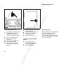
Arrows on the deflector $ and stop %
show the correct direction of rotation of
the cutting tool.
7+(%586+&877(5
000BA006
A
For illustrations and definitions of the
brushcutter parts see the chapter on
"Parts and Controls"
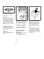
7UDQVSRUWLQJWKHEUXVKFXWWHU
:DUQLQJ
000BA007
)XHOLQJ
3UHSDUDWLRQIRUWKHXVHRIWKH
EUXVKFXWWHU
Adjust carrying harness and hand grip
to suit your size before starting work.
The machine should be properly
balanced as specified in your owner’s
manual for proper control and less
fatique in operation.
-n
o
t
f
o
r
r
Always turn off the engine and make
sure the cutting attachment has stopped before putting a brushcutter down.
When transporting your brushcutter in
a vehicle, properly secure it to prevent
turnover, fuel spillage and damage to
the brushcutter. Keep metal cutting
tools covered with the transport guard
(optional accessory).
B
e
r
s
i
o
n
7+(86(2)7+(%586+&877(5
O
n
l
i
n
e
v
:DUQLQJ
Never modify a brushcutter in any way.
Only attachments supplied by STIHL or
expressly approved by STIHL for use
with the specific STIHL brushcutter
models are authorized. Although certain
unauthorized attachments are useable
for the STIHL brushcutter, their use
may, in fact, be extremely dangerous.
The throttle trigger must move freely
and always spring back to the idle
position.The cutting tool must be
properly tightened and in safe operating
condition. Inspect for loose parts (nuts,
screws, etc.) and for cracked, bent,
warped or damaged blades.
Always check your brushcutter for proper
condition and operation before starting,
particularly the throttle trigger, throttle
trigger interlock (if applicable), stop
switch, cutting tool, deflector and
harness.
Your STIHL brushcutter uses an oilgasoline mixture for fuel (see the chapter on "Fuel" of your owner’s manual).
:DUQLQJ
Gasoline is an extremely
flammable fuel. If spilled and
ignited by a spark or other
ignition source, it can cause
fire and serious burn injury or property
damage. Use extreme caution when
handling gasoline or fuel mix.
Do not smoke or bring any fire or flame
near the fuel.
e
p
r
i
n
t
:DUQLQJ
)XHOLQJ,QVWUXFWLRQV
Fuel your brushcutter in well-ventilated
areas, outdoors.
2SHUDWLQJLQVWUXFWLRQV
:DUQLQJ
:DUQLQJ
Your brushcutter is a one-person
machine. Once started, it may fling
foreign objects for a great distance.
O
n
l
i
n
e
v
Improper use of any brushcutter can
cause serious or fatal personal injury.
Read, understand and follow all safety
instructions in your owner’s manual
before operating these products. To
reduce the risk of personal injury to the
operator from blade contact and thrown
objects, make sure your unit is equipped
with the proper deflector, handle and
harness for the type of cutting attachment being used (see chart in chapter
on "Selecting the Cutting Tool").
Always wear proper eye protection.
-n
o
t
f
o
r
r
:DUQLQJ
Check for fuel leakage while refueling
and during operation. If fuel or oil
leakage is found, do not start or run the
engine until leak is fixed and spilled fuel
has been wiped away. If this happens,
change your clothing immediately.
Unit vibrations can
cause an improperly
tightened fuel cap to
loosen or come off and
spill quantities of fuel.
In order to reduce risk of fuel spillage
and fire, tighten fuel cap by hand with as
much force as possible.
The screwdriver end of the STIHL
combination wrench or other similar tool
can be used as an aid for tightening
slotted fuel caps.
e
r
s
i
o
n
:DUQLQJ
Gasoline vapor pressure may build up
inside the gas tank of a two cycle engine
depending on the fuel used, the weather
conditions, and the venting system of
the tank. In order to reduce the risk of
burns and other personal injury from
escaping gas vapor and fumes, remove
the fuel filler cap on your brushcutter
carefully so as to allow any pressure
build-up in the tank to release slowly.
Never remove fuel filler cap while engine
is running. Select bare ground for fueling
and move at least 10 feet (3 m) from the
fueling spot before starting the engine.
Wipe off any spilled fuel before starting
your brushcutter and check for leakage.
6WDUWLQJ
To reduce the risk of eye and other injury
insure that bystanders are at least 50
feet (15 m) away. Stop the engine and
cutting tool immediately if you are
approached. Start and operate your
brushcutter without assistance. For
specific starting instructions, see the
appropriate section of your manual.
Place the brushcutter on firm ground or
other solid surface in an open area.
Maintain a good balance and secure
footing.
e
p
r
i
n
t
:DUQLQJ
:RUNLQJ&RQGLWLRQV
With the engine running but at idle,
attach the brushcutter to the spring hook
of your harness (see appropriate
chapter of this manual).
:DUQLQJ
Your brushcutter
produces toxic exhaust
fumes as soon as the
engine is running. These
gases (e.g. carbon
monoxide) may be colourless and
odourless. To reduce the risk of serious
or fatal injury from inhaling toxic fumes,
never run the brushcutter indoors or in
poorly ventilated locations.
:DUQLQJ
e
r
s
i
o
n
:DUQLQJ
When you pull the starter grip, don’t
wrap the starter rope around your hand.
Do not allow the grip to snap back, but
guide the starter rope to rewind it
properly. Failure to follow this procedure
may result in injury to hand or fingers and
may damage the starter mechanism.
Operate and start your brushcutter only
outdoors in a ventilated area.
-n
o
t
f
o
r
r
Use of this product can generate dust
and fumes containing chemicals known
to cause respiratory disease, cancer,
birth defects, or other reproductive harm.
If you are unfamiliar with the risks associated with the particular dust or fume at
issue, consult your employer, governmental agencies such as OSHA and
NIOSH and other sources on hazardous
materials. California and some other
authorities, for instance, have published
lists of substances known to cause
cancer, reproductive toxicity, etc.
Control dust and fumes at the source
where possible. In this regard use good
work practices and follow the recommendations of OSHA/NIOSH and occupational and trade associations. When the
:DUQLQJ
O
n
l
i
n
e
v
To reduce the risk of injury from loss
of control, be absolutely sure that the
cutting tool is clear of you and all other
obstructions and objects, including the
ground, because when the engine starts
at starting-throttle, engine speed will be
fast enough for the clutch to engage and
turn the cutting tool.
inhalation of toxic dust and fumes cannot be eliminated, the operator and any
bystanders should always wear a respirator approved by NIOSH/MSHA for the
type of dust and / or fumes encountered.
The muffler and other parts of the engine
(e.g. fins of the cylinder, spark plug)
become hot during operation and remain
hot for a while after stopping the engine.
To reduce risk of burns do not touch the
muffler and other parts while they are
hot.
Operate the brushcutter under good
visibility and daylight conditions only.
Work carefully.
Do not cut any material other than
grass, brush and wood. The cutting
tools may be used only for the
operations described in your manual.
e
p
r
i
n
t
002BA054 KN
002BA055 KN
To reduce the
risk of injury
from thrown
objects and
blade contact,
never operate a brushcutter without a
properly mounted deflector. Keep the
deflector (and the skirt where appropriate) adjusted properly at all times (see
chapter on mounting the various cutting
tools of your owner’s manual). Do not
overreach. Keep proper footing and
balance at all times.
002BA024 LÄ
002BA025 LÄ
O
n
l
i
n
e
v
e
r
s
i
o
n
:DUQLQJ
Never attempt to operate any brushcutter with one hand. Loss of control of
the brushcutter resulting in serious or
fatal injury may result.
To reduce the risk of bodily injury
resulting from loss of control and/or
contact with the cutting tool, make sure
your unit is equipped with the proper
handle and harness for the type of
cutting attachment being used (see
chart in chapter on "Selecting the
Cutting Tool").
Special care must be taken in slippery
conditions (wet ground, snow) and in
difficult, overgrown terrain. Watch for
hidden obstacles such as tree stumps,
roots and ditches to avoid stumbling.
-n
o
t
f
o
r
r
Always hold the brushcutter firmly with
both hands. Wrap your fingers tightly
around the handles, keeping the
handles cradled between your thumb
and forefinger. Keep your hands in this
position, to have your brushcutter under
control at all times. Make sure your
brushcutter handles and grip are in
good condition and free of moisture,
pitch, oil or grease.
Before cutting, inspect the
area for stones, glass,
pieces of metal, trash or
other solid objects. The
cutting attachment could throw objects
of this kind.
:DUQLQJ
This brushcutter is normally to be used
at ground level with the cutting attachment parallel to the ground. Use of a
brushcutter above ground level or with
the cutting attachment perpendicular to
the ground may increase the risk of
injury, since the cutting attachment is
more fully exposed and the brushcutter
may be more difficult to control. Never
use your brushcutter as a hedge
trimmer.
e
p
r
i
n
t
:DUQLQJ
Do not operate using the starting
throttle lock as you do not have control
of the engine speed. See section of your
owner’s manual on the proper use of the
slide control.
:DUQLQJ
Keep hands and feet
away from cutting
tool. Never touch a
rotating cutting tool
with your hand or any part
of your body. It continues to rotate for a
short period after the throttle trigger is
released (flywheel effect).
-n
o
t
f
o
r
r
:DUQLQJ
During cutting, check the tightness and
the condition of the cutting tool at
regular intervals. If the behavior of the
tool changes, stop the engine immediately, and check the nut securing
the tool for tightness and the cutting
tool for cracks and damage. Replace
cracked, bent, warped, damaged or dull
cutting tools immediately. Such tools
may shatter at high speed and cause
serious or fatal injury.
A loose blade may cause the blade to
vibrate, crack, break or come off the
brushcutter, which may result in
serious or fatal injury. Make sure that
the blade is properly tightened. Use the
wrench supplied or one of sufficient
length to obtain the proper torque. If the
blade loosens after being properly
tightened, stop work immediately. The
retaining nut may be worn or damaged
and should be replaced. Never use
unauthorized parts to secure the blade.
If the blade continues to loosen, see
your STIHL dealer. Never use a
brushcutter with a loose blade.
e
r
s
i
o
n
If the cutting tool or deflector becomes
clogged or stuck, always turn off the
engine and make sure the cutting tool
has stopped, before cleaning. Grass,
weeds, etc. should be cleaned off the
cutting tool at regular intervals.
,PSRUWDQWDGMXVWPHQWV
:DUQLQJ
To reduce the risk of personal injury
from loss of control or contact with the
running cutting tool, do not use a cutting
tool with incorrect idle adjustment. At
correct idle speed, the cutting tool
should not move. For directions on how
to adjust idle speed, see the appropriate
section of your owner’s manual.
O
n
l
i
n
e
v
When using rigid blades, avoid cutting
close to fences, sides of buildings, tree
trunks, stones or other such objects
that could cause the brushcutter to kick
out or could cause damage to the
blade. STIHL recommends use of the
nylon line heads or Polycut head for
such jobs. In addition, be alert to an
increased possibility of ricochets in
such situations.
:DUQLQJ
If you cannot set the correct idle speed,
have your STIHL dealer check your
brushcutter and make proper
adjustments and repairs
e
p
r
i
n
t
:DUQLQJ
0$,17(1$1&(5(3$,5$1'
6725,1*
Use only identical STIHL replacement
parts for maintenance and repair.
Use of non-STIHL parts may cause
serious or fatal injury.
Check condition of cutting tool at regular
short intervals. If behavior of tool
changes, check it immediately for tightness or any signs of cracks in
particular. Replace damaged or dull
cutting tools immediately, even if they
have only superficial cracks. If the
blade loosens after being properly
tightened, the retaining nut may be
worn or damaged and should be
replaced. If the blade continues to
loosen, see your STIHL dealer. Do not
attach any blade to a unit without
proper installation of all required parts.
Never use unauthorized parts to secure
the blade. Failure to use the proper
parts may cause the blade to fly off
and seriously injure the operator or
bystanders.
-n
o
t
f
o
r
r
:DUQLQJ
Always stop the engine and make sure
that the cutting tool is stopped before
doing any maintenance or repair work or
cleaning the brushcutter. Do not attempt
any maintenance or repair work not
described in your owner’s manual. Have
such work performed at your STIHL
service shop only.
:DUQLQJ
e
r
s
i
o
n
Follow the maintenance and repair
instructions in the appropriate section of
your owner’s manual. Please refer to the
maintenance chart at the last pages of
this manual.
:DUQLQJ
To reduce the risk of fire and burn
injuries, check fuel filler cap for leaks at
regular intervals. Use the specified
spark plug and make sure it and the
ignition lead are always in good
condition.
O
n
l
i
n
e
v
0DLQWHQDQFHUHSODFHPHQWRUUHSDLU
RIWKHHPLVVLRQFRQWUROGHYLFHVDQG
V\VWHPVPD\EHSHUIRUPHGE\DQ\
QRQURDGHQJLQHUHSDLUHVWDEOLVKPHQW
RULQGLYLGXDO+RZHYHULI\RXFODLP
ZDUUDQW\IRUDFRPSRQHQWZKLFKKDV
QRWEHHQVHUYLFHGRUPDLQWDLQHGSUR
SHUO\RULIQRQDSSURYHGUHSODFHPHQW
SDUWVZHUHXVHG67,+/PD\GHQ\
ZDUUDQW\
Never repair damaged cutting attachments by welding, straightening or
modifying the shape. This may cause
parts of the cutting tool to come off and
result in serious or fatal injuries.
:DUQLQJ
Never test the ignition system with
ignition wire boot removed from
spark plug or with unseated spark plug,
since uncontained sparking may cause
a fire.
:DUQLQJ
To reduce the risk of fire and burn injury,
use only spark plugs authorized by
STIHL. Always press spark plug boot
snugly onto spark plug boot of the
proper size. (Note: If boot has
detachable SAE adapter nut, it must be
attached.) A loose connection between
spark plug boot and ignition wire
connector in the boot may create arcing
that could ignite combustible fumes and
cause a fire. Keep spark plug clean, and
make sure ignition lead is in good
condition.
e
p
r
i
n
t
O
n
l
i
n
e
v
:DUQLQJ
Do not operate your brushcutter if the
muffler is damaged, missing or modified.
An improperly maintained muffler will
increase the risk of fire and hearing loss.
Never touch a hot muffler or burn will
result. If your muffler was equipped with
a spark-arresting screen to reduce the
risk of fire (e.g. in the USA, Canada and
Australia), never operate your brushcutter if the screen is missing or
damaged. Do not modify or remove any
part of the muffler or spark arresting
screen. Remember that the risk of forest
fires is greater in hot or dry weather.
e
r
s
i
o
n
Keep cutting tool sharp. Tighten all nuts,
bolts and screws, except the carburetor
adjustment screws, after each use.
Additionally, the daily maintenance
schedule for your brushcutter set forth
in your STIHL Owner’s Manual should
be strictly followed.
For any maintenance please refer to the
maintenance chart DQGWRWKHZDUUDQW\
VWDWHPHQW near the end of this manual.
Before storing for longer than a few
days, always empty the fuel tank.
-n
o
t
f
o
r
r
Store brushcutter in a dry, high or
locked location out of reach of children.
e
p
r
i
n
t
:DUQLQJ
O
n
l
i
n
e
v
To reduce the risk of serious injury,
never use wire or metal-reinforced line
or other material in place of the nylon
cutting lines. Pieces of wire could break
off and be thrown at high speed toward
the operator or bystanders.
For an illustration of the various cutting
tools and instructions on proper mounting see the chapter on "mounting the
cutting tools" in your owner’s manual.
8VLQJWKHPRZLQJKHDGV
They are to be used only on brushcutters equipped with a limiter blade in the
deflector in order to keep the line at the
proper length (see "Parts and
Controls" chapter of this manual).
If the lawn edges are planted with trees
or bordered by a fence etc., it is best to
use a nylon line head. It achieves a
"softer" cut with less risk of damaging
tree bark etc. than with the polymer
blades.
However, the polymer bladed STIHL
"Polycut" produces a better cut if there
are no plants along the edge of the lawn.
Sharpening is not necessary and worn
cutting blades are easily replaced.
-n
o
t
f
o
r
r
The STIHL Supercut, Autocut, Polymatic
and Polycut mowing heads produce a
clean and tidy finish.
e
r
s
i
o
n
86,1*7+(&877,1*722/6
000BA015
002BA018 LÄ
67,+/6XSHUFXW PRZLQJKHDG
Fresh line is advanced automatically.
Frayed line is replaced by a simple
adjustment (see instruction sheet
supplied with mowing head).
67,+/3RO\PDWLFPRZLQJKHDG
Frayed line is replaced by a simple
adjustment (see instruction sheet
supplied with mowing head).
67,+/$XWRFXW PRZLQJKHDG
Nylon cutting cord advances automatically when tapped against the
ground.
e
p
r
i
n
t
Uses either nylon lines or nonrigid
plastic blades
:DUQLQJ
To reduce the risk of serious or fatal
injury never attempt to cut woody
materials.
The WRRWK grass cutting blade is
intended to cut grass and weeds.
It has 4 cutting knives with cutting edges
on both sides, i.e. front and rear.
The WRRWK grass cutting blade is
recommended for cutting fern or reed.
Both blades have to be resharpened
when all cutting edges are dull.
-n
o
t
f
o
r
r
8VLQJWKHJUDVVFXWWLQJEODGH
All kinds of grass and weeds can be
easily cut with the grass cutting blade.
The brushcutter is swept in an arc
similiar to a scythe.
e
r
s
i
o
n
,PSRUWDQW
Three rectangular wear limit marks are
applied to the base (periphery) of the
Polycut. To reduce the risk of serious
injury from breakage of the head or
blades, the Polycut must not be used
when it has worn as far as one of these
marks. It is important to follow the
maintenance instructions supplied with
the head!
5LVNRINLFNRXWEODGHWKUXVW
ZLWKDOOULJLGFXWWLQJEODGHV
:DUQLQJ
000BA012 KN
002BA049 KN
O
n
l
i
n
e
v
67,+/3RO\FXWPRZLQJKHDG
when the shaded area of the rotating
blade comes in contact with a solid
object like a tree, rock, bush or wall.
The rapid counterclockwise rotation of
the blade may be stopped or slowed,
and the cutting attachment may be
thrown in an area to the right or to the
rear.
This kickout (blade thrust) may cause
loss of control of the brushcutter and
may result in serious or fatal injury to the
operator or bystanders. To reduce the
risk of injury, extreme caution should be
used when cutting with the shaded area
of any rigid blade.
Kickout (blade thrust) is the sudden and
uncontrolled motion towards the
operator’s right or rear that can occur
e
p
r
i
n
t
6HOHFWLQJWKH&XWWLQJ7RRO
&XWWLQJWRROV
STIHL Supercut 20-2 mowing head
STIHL Autocut 20-2 mowing head
STIHL Autocut 24-2 mowing head
STIHL Autocut 25-2 mowing head
STIHL Polymatic 30-2 mowing head
STIHL Polycut 20-3 mowing head
STIHL Fixed Line head
A fully equipped brushcutter comprises,
among other items:
STIHL brushcutters with a loop handle
ZLWKRXWVWDQGRIIOHYHU may be used
only with the above-mentioned mowing
heads with nylon line or plastic blades.
Cutting tool
Deflector
Handle
Carrying strap
Grass cutting blade 230-4
Grass cutting blade 230-8
6HOHFWWKHFRUUHFWFRPELQDWLRQIURP
WKHWDEOHDFFRUGLQJWRWKHFXWWLQJWRRO
\RXLQWHQGWRXVH
'HIOHFWRUV
Deflector for mowing heads
Deflector for all cutting tools
ZLWK
Skirt and line limiting blade
Deflector for all cutting tools
ZLWKRXW skirt and line limiting blade
For safety reasons, you may only combine the cutting tool, deflector, handle and
carrying strap versions shown when you
read WKHWDEOHKRUL]RQWDOO\IURPOHIWWR
ULJKW.
+DQGOHV
Loop handle
Loop handle ZLWK
Standoff lever
J-handle
Bike handle
-n
o
t
f
o
r
r
&DUU\LQJVWUDSV
Shoulder strap recommended
Shoulder strap
Full harness recommended
2WKHUFRPELQDWLRQV, e.g. reading the
table diagonally, DUHQRWSHUPLWWHG
VLQFHWKHUHLVRWKHUZLVHDULVNRI
VHULRXVLQMXU\
e
r
s
i
o
n
:DUQLQJ
Other plastic or metal cutting tools may
only be used on brushcutters with a bike
handle, "J"-handle or loop handle ZLWK
VWDQGRIIOHYHU in order to minimize the
risk of personal injury through contact
with the cutting tool.
O
n
l
i
n
e
v
e
p
r
i
n
t
&XWWLQJ7RRO
'HIOHFWRU
+DQGOH
&DUU\LQJ6WUDS
681FK006
e
r
s
i
o
n
-n
o
t
f
o
r
r
O
n
l
i
n
e
v
e
p
r
i
n
t
0RXQWLQJWKH%LNH+DQGOH
6
6
11
5
4
10
7
3
9
7
A
12
8
2
1
1
2
•
•
13
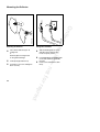
0RXQWLQJWKHFRQWUROKDQGOH
6HFXULQJWKHWKURWWOHFDEOH
•
•
•
•
•
•
•
•
Remove the screw from the nut .
Take both parts out of
the control handle .
Push the control handle
onto the bike handle throttle trigger must
point in direction of gear head.
Line up the holes .
Fit nut and screw in the
control handle.
Tighten the screw firmly.
-n
o
t
f
o
r
r
•
•
•
•
•
Mount the bike handle on the
drive tube - 30cm/12" $
forward of the engine.
Position the clamp and
support on the drive tube.
Place the bike handle in the
support so that the molded handle
is on the left (looking at handle from
engine).
Fit clamp on support.
Insert screws in holes.
Fit nuts on screws - fingertight.
Line up the bike handle as required.
Tighten the screws firmly.
e
r
s
i
o
n
•
12
O
n
l
i
n
e
v
1
Lay your brushcutter on its back
with the gear gear facing up.
Push the throttle cable retainers
into the holes on the underside
of the drive tube.
e
p
r
i
n
t
0RXQWLQJWKH-+DQGOH
6
0RXQWLQJ/RRS+DQGOHZLWK
6WDQGRII/HYHU
3
6
5
A
1
2
7
3
2
7
A
1
•
•
•
0RXQWWKHORRSKDQGOH with
standoff lever 20 cm/8" $ forward
of the control handle .
-n
o
t
f
o
r
r
•
•
•
•
•
Mount the "J" handle on the drive tube 20cm/8" $ forward of the
throttle trigger block.
Position the clamp and support
on the drive tube.
Place "J" handle in the support handle must point to left (looking at
handle from engine).
Place clamp on support Insert screws through the parts
and fit the nuts - fingertight.
Locate the plug against the
support .
Line up the "J" handle as required.
Tighten the screws firmly.
e
r
s
i
o
n
•
343BA055 K
2
3
•
4
4
3
002BA010 K
4
O
n
l
i
n
e
v
1
8
3
Insert square nuts in the
standoff lever ) line up the holes.
e
p
r
i
n
t
0RXQWLQJWKH/RRS+DQGOH
9HUVLRQ$
$
A
1
1
2
6
•
•
•
Mount the loop handle 20 cm/8" $ forward of the
control handle .
-n
o
t
f
o
r
r
•
•
Place the clamp in the loop
handle and position them both
against the drive tube .
Fit the clamp and place standoff
lever in position line up the holes.
Insert screws in holes and
screw them into standoff lever
fingertight.
Align the loop handle.
Tighten the screws firmly.
e
r
s
i
o
n
•
8
343BA056 K
8
002BA011 K
7
O
n
l
i
n
e
v
1
5
6
6
7
•
•
•
•
•
3
4
5
7
02BA012 K
4
Place the clamp in the loop
handle and position them both
against the drive tube .
Fit the clamp line up the holes.
Insert screws in holes and
screw on the nuts fingertight.
Align the loop handle.
Lock the nuts and tighten
the screws firmly.
e
p
r
i
n
t
0RXQWLQJWKH/RRS+DQGOH
9HUVLRQ%
002BA007 KN
%
1
A
3
•
Mount the loop handle on the drive tube 15cm/6" $ forward of the
control handle .
Position clamp against the
drive tube and slide it into the loop
handle.
43BA023 KN
343BA058 K
5
50 mm
( 2" )
•
•
e
r
s
i
o
n
•
O
n
l
i
n
e
v
4
2
Fit square nut in the loop handle.
Insert the clamp screw from
the other side and tighten down
securely.
$GMXVWLQJORRSKDQGOHWRPRVW
FRPIRUWDEOHSRVLWLRQ
Release clamp screw .
Move the loop handle along the
drive tube as required and then
tighten the clamp screw.
-n
o
t
f
o
r
r
•
•
e
p
r
i
n
t
0RXQWLQJWKH'HIOHFWRU
357BA007 KN
357BA008 KN
O
n
l
i
n
e
v
)LWWLQJVNLUWDQGEODGH
•
•
•
Fit the plate and line it up.
Insert M 5 x 18 screws and tighten
down securely.
•
Slide the ORZHU guide slot of the
skirt over the deflector it must snap into position.
Push blade into the XSSHU guide
on the skirt and line it up with the
first hole.
Fit the screw and tighten it down
firmly.
-n
o
t
f
o
r
r
•
•
Place either deflector for all
cutting tools
or
deflector for mowing heads
on the gearhead flange.
e
r
s
i
o
n
0RXQWLQJWKHGHIOHFWRU
e
p
r
i
n
t
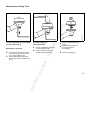
0RXQWLQJWKH&XWWLQJ7RROV
3
O
n
l
i
n
e
v
2
1
5HPRYLQJFXWWLQJWRRO
PRXQWLQJKDUGZDUH
%ORFNLQJWKHRXWSXWVKDIW
•
•
•
Position combination wrench on the mounting nut .
Release and unscrew the nut
clockwise (left-hand thread).
-n
o
t
f
o
r
r
•
Insert stop pin in the bore at
the side of the gear head as far as
stop - apply slight pressure.
Rotate output shaft until the stop
pin slips into position and blocks the
shaft.
e
r
s
i
o
n
/D\\RXUEUXVKFXWWHURQLWVEDFNZLWK
WKHJHDUKHDGIDFLQJXS
•
•
•
357BA014 KN
4
Remove shipping keeper if fitted.
Pull the rider plate and
thrust washer off
the shaft .
Now fit the cutting tool.
e
p
r
i
n
t
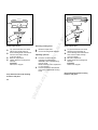
5HPRYLQJPRZLQJKHDG
67,+/3RO\FXW
•
•
•
•
•
•
•
•
$GMXVWLQJQ\ORQOLQH
•
•
.HHSLQVWUXFWLRQVKHHWIRUPRZLQJ
KHDGLQDVDIHSODFH
Block the output shaft unscrew mowing head clockwise.
Fresh line is advanced automatically, providing at least
FP of line is still projecting
from the head.
Blade on deflector trims surplus line
to correct length.
Fit new nylon line as described in
instructions supplied with mowing
head.
-n
o
t
f
o
r
r
Lay your brushcutter on its back
with the gear head facing up.
Screw mowing head counterclockwise onto the output shaft as far as it will go.
Block the output shaft.
Tighten down the mowing head
securely.
,PSRUWDQW
Remove the stop pin.
•
•
343BA024
357BA015 KN
O
n
l
i
n
e
v
e
r
s
i
o
n
67,+/6XSHUFXW
Lay your brushcutter on its back
with the gear head facing up.
Screw mowing head counterclockwise onto the output shaft as far as it will go.
Block the output shaft.
Tighten down the mowing head
securely.
,PSRUWDQW
Remove the stop pin.
.HHSLQVWUXFWLRQVKHHWIRUPRZLQJ
KHDGLQDVDIHSODFH
e
p
r
i
n
t
Block the output shaft unscrew mowing head clockwise.
5HSODFLQJFXWWLQJEODGHV
•
•
•
Push the bolt into
the mowing head and
engage it in the hexagon recess.
Screw the cap counterclockwise
on to the bolt and tighten it down
securely.
-n
o
t
f
o
r
r
Refer to instruction sheet supplied
with mowing head.
$VVHPEOLQJ67,+/$XWRFXW
.HHSLQVWUXFWLRQVKHHWIRUPRZLQJ
KHDGLQDVDIHSODFH
343ET026
343BA025
O
n
l
i
n
e
v
•
67,+/$XWRFXW
67,+/$XWRFXW
e
r
s
i
o
n
5HPRYLQJPRZLQJKHDG
0RXQWLQJWKHPRZLQJKHDG
•
•
•
•
Lay your brushcutter on its back
with the gear head facing up.
Screw mowing head counterclockwise onto the output shaft as far as it will go.
Block the output shaft.
Tighten down the mowing head
securely.
,PSRUWDQW
Remove the stop pin.
5HPRYLQJPRZLQJKHDG
•
Block the output shaft unscrew mowing head clockwise.
e
p
r
i
n
t
357BA017 KN
O
n
l
i
n
e
v
•
•
•
•
•
•
•
Lay your brushcutter on its back
with the gear head facing up.
Slip the plain washer and
thrust washer over the
shaft and against the
thrust plate .
Screw mowing head counterclockwise onto the output shaft as far as it will go.
Block the output shaft.
Tighten down the mowing head
securely.
,PSRUWDQW
Remove the stop pin.
-n
o
t
f
o
r
r
•
Hold the rotating mowing head
horizontal above the ground tap it on the ground DERXWFP fresh line is
advanced - blade on deflector trims
surplus line to the correct length avoid tapping head more than
once.
Line feed operates only if
both lines still have a
PLQLPXPOHQJWKRIFP.
Fit new nylon line as described in instructions supplied with mowing
head.
e
r
s
i
o
n
67,+/3RO\PDWLF
67,+/$XWRFXW
$GMXVWLQJQ\ORQOLQH
.HHSLQVWUXFWLRQVKHHWIRUPRZLQJ
KHDGLQDVDIHSODFH
5HPRYLQJPRZLQJKHDG
•
Block the output shaft unscrew mowing head clockwise.
$GMXVWLQJQ\ORQOLQH
•
Refer to instruction sheet supplied
with mowing head.
e
p
r
i
n
t
357BA019 KN
O
n
l
i
n
e
v
e
r
s
i
o
n
67,+/)L[HG/LQH+HDG
5HOHDVLQJPRXQWLQJQXW
•
•
•
•
•
•
.HHSLQVWUXFWLRQVKHHWIRUPRZLQJ
KHDGLQDVDIHSODFH
Block the output shaft and
unscrew the mounting nut
clockwise.
If the mounting nut becomes slack due
to frequent loosening and retightening,
fit a new one.
-n
o
t
f
o
r
r
Lay your brushcutter on its back
with the gear head facing up.
Position the head on the thrust
plate .
Slip the thrust washer over the
output shaft .
Block the output shaft.
Screw mounting nut counterclockwise on to the output shaft and
tighten it down firmly.
,PSRUWDQW
Remove the stop pin.
)LWWLQJQ\ORQOLQH
•
Refer to instruction sheet supplied
with fixed line head.
e
p
r
i
n
t
)XHO
8
3
4
6
O
n
l
i
n
e
v
5
1
7
343BA010 KN
2
1RWH Remove skirt and blade from
deflector before mounting this
cutting tool.
Lay your brushcutter on its back
with the gear head facing up.
Place cutting tool on the thrust
plate .
Cutting edges of blade 230-8 must point clockwise.
Cutting blade 230-4 may be
fitted either way round.
•
•
Slip the thrust washer and rider plate over
the output shaft .
Block the output shaft.
Screw mounting nut counterclockwise on to output shaft and
tighten down securely.
,PSRUWDQW
Remove the stop pin.
-n
o
t
f
o
r
r
•
•
•
•
•
e
r
s
i
o
n
*UDVVFXWWLQJEODGH
5HOHDVLQJPRXQWLQJQXW
•
Block the output shaft and unscrew
the mounting nut clockwise.
If the mounting nut becomes slack due
to frequent loosening and retightening,
fit a new one.
This engine is certified to operate on
unleaded gasoline and with the
mix ratio 50:1.
Your two-stroke engine requires a
mixture of brand-name gasoline and
quality two-stroke engine oil with the
classification TC.
Use regular branded unleaded gasoline
with a minimum octane rating of
90 RON (U.S.A./Canada: pump octane
min. 89!). If the octane number of the
regular grade gasoline in your area is
lower use premium unleaded fuel.
Fuel with a lower octane rating may
result in preignition (causing "pinging")
which is accompanied by an increase in
engine temperature. This, in turn,
e
p
r
i
n
t
O
n
l
i
n
e
v
e
r
s
i
o
n
increases the risk of the piston seizure
and damage to the engine.
We recommend STIHL 50:1 two-stroke
engine oil since it is specially formulated
for use in STIHL engines.
Use only STIHL two-stroke engine oil or
equivalent branded two-stroke aircooled engine oils with the classification
TC for mixing.
Do not use BIA or TCW (two-stroke
water cooled) mix oils!
Take care when handling gasoline.
Avoid direct contact with the skin and
avoid inhaling fuel vapour.
-n
o
t
f
o
r
r
The chemical composition of the fuel is
also important. Some fuel additives not
only detrimentally affect elastomers
(carburetor diaphragms, oil seals, fuel
lines etc.), but magnesium castings as
well. This could cause running problems
or even damage the engine. For this
reason it is essential that you use only
name branded fuels!
The canister should be kept tightly
closed in order to avoid any moisture
getting into the mixture.
The fuel tank and the canister in which
fuel mix is stored should be cleaned
from time to time.
)XHOPL[DJHV
Only mix sufficient fuel for a few days
work, not to exceed 3 months of storage.
Store in approved safety fuel-canisters
only. When mixing, pour oil into the
canister first, and then add gasoline.
Gasoline
Oil (STIHL 50:1 or
equivalent branded TC oils)
US gal.
US fl.oz
1
2 1/2
5
2.6
6.4
12.8
Dispose empty mixing-oil canisters only
at authorized disposal locations.
e
p
r
i
n
t
)XHOLQJ
)LWWLQJWKH+DUQHVV
1
343BA028
343BA027
O
n
l
i
n
e
v
e
r
s
i
o
n
Before fueling, clean the filler cap
and the area around it to ensure that no
dirt falls into the tank.
Before storing your machine for a long
period, drain and clean the fuel tank and
run engine until carburetor is dry.
Always thoroughly shake the mixture in
the canister before fueling your machine.
:DUQLQJ
After fueling, tighten fuel cap
as securely as possible by hand.
Change the fuel pick up body every year.
-n
o
t
f
o
r
r
:DUQLQJ
In order to reduce the risk of burns or
other personal injury from escaping gas
vapor and fumes, remove the fuel filler
cap carefully so as to allow any pressure
build-up in the tank to release slowly.
3
Models with a loop handle come without
a harness (available as special accessory for these models).
6KRXOGHUVWUDS
•
•
Put on the shoulder strap .
Adjust length until the spring
hook rests against your right hip.
Special accessory
e
p
r
i
n
t
2
3
O
n
l
i
n
e
v
4
3
5
e
r
s
i
o
n
)XOOKDUQHVV
%DODQFLQJWKHEUXVKFXWWHU
•
•
•
Put on the full harness .
Adjust length until the spring
hook rests against your right hip.
•
•
Attach the spring hook to
the clamp on the drive shaft.
slacken the screw .
Slide the clamp up or down
the drive shaft.
Tighten the screw moderately.
•
•
Let go of the brushcutter and check
to see how it is balanced.
In normal working position, cutting
tool must just touch the ground.
Tighten the screw firmly.
-n
o
t
f
o
r
r
e
p
r
i
n
t
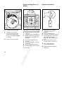
IfHQJLQHLVFROG:
•
Turn filter cover clockwise to
&+2.(.
IfHQJLQHLVZDUP:
•
Turn filter cover counterclockwise to581.
-n
o
t
f
o
r
r
•
•
Hold down the throttle trigger
interlock and squeeze
the throttle trigger .
Move the slide control to67$57 position.
Now release the throttle trigger,
slide control and trigger interlock
in that order = This is the
VWDUWLQJWKURWWOHSRVLWLRQ
343BA029
357BA030 KN
O
n
l
i
n
e
v
•
Observe safety precautions - see
chapter "Safety Precautions and
Working Techniques".
e
r
s
i
o
n
•
Also use this setting if engine has been
running but is still cold.
•
343BA031
6WDUWLQJ
9HUVLRQZLWK%LNH+DQGOH
Press transparent fuel pump bulb at
least five times
- it must be filled with fuel.
e
p
r
i
n
t
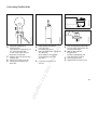
Pull the starter grip slowly with your
right hand until you feel it engage and then give it a brisk strong pull.
Do not pull out starter rope more
than 70cm (27") - it might break.
Do not let the starter grip snap
back - guide it slowly into the
housing so that the starter rope
can rewind properly.
-n
o
t
f
o
r
r
•
•
343BA032
O
n
l
i
n
e
v
•
Put the unit on the ground:
It must rest securely on the engine
support and deflector. Check that
the cutting tool is not touching the
ground or any other obstacles.
Make sure you have a firm
footing: Hold the unit with you left
hand and press it down ILUPO\ your thumb should be under the drive shaft.
Do not stand or kneel on the drive
shaft!
e
r
s
i
o
n
•
:KHQHQJLQHEHJLQVWRILUH
•
If HQJLQHLVFROG
Turn filter cover counterclockwise until mark on filter cover
points to N
continue cranking until engine runs.
•
If HQJLQHLVZDUP
Continue cranking until engine runs.
e
p
r
i
n
t
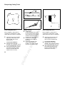
•
•
Turn filter cover to 581.
Blip the throttle trigger the slide control moves to the
"Run" position and the engine
returns to idling speed.
-n
o
t
f
o
r
r
•
Squeeze the throttle trigger warm up engine for brief period at
full throttle.
Release throttle trigger slide control moves to the
"Run" position , and the engine
returns to idling speed.
•
Make sure carburetor is correctly
adjusted - cutting tool must not
rotate when engine is idling.
Your brushcutter is ready for
operation.
7RVKXWGRZQWKHHQJLQH
Move slide control to6723.
357BA036 KN
357BA035 KN
357BA035 KN
O
n
l
i
n
e
v
If HQJLQHLVFROG
If HQJLQHLVZDUP
e
r
s
i
o
n
$VVRRQDVHQJLQHUXQV
e
p
r
i
n
t
Turn filter cover to 581.
•
•
•
•
•
•
If you did not turn the
filter cover to 581 quickly
enough after the engine began
to fire, the combustion chamber
is flooded.
Remove spark plug boot .
Unscrew and dry off the
spark plug.
Set slide control to 6723.
Open the throttle fully.
Pull the starter rope several times
to clear the combustion chamber.
-n
o
t
f
o
r
r
•
As soon as engine runs:
Warm up engine for about 1 minute
at full throttle.
Release throttle trigger slide control moves to the
"Run" position and the engine
returns to idling speed.
•
•
•
•
343BA035
343BA034
O
n
l
i
n
e
v
•
•
e
r
s
i
o
n
,IWKHHQJLQHGRHVQ¶WVWDUW
$WYHU\ORZRXWVLGHWHPSHUDWXUHV
$OORZHQJLQHWRZDUPXS
Refit the spark plug and connect
the spark plug boot.
Set slide control to 67$57 .
Turn filter cover to 581,
even if engine is cold.
Now start the engine.
)XHOWDQNUXQXQWLOGU\DQGWKHQ
UHIXHOHG
•
•
Press transparent fuel pump bulb
several times - it must be filled
with fuel.
Now start the engine.
e
p
r
i
n
t
•
•
•
Move stop switch to Hold down the interlock lever ,
squeeze the throttle trigger and
engage the spring lock in the
notch (see arrow) on the throttle
trigger retainer.
Let go of the throttle trigger, spring
lock and interlock lever in that
order. The trigger is now in the VWDU
WLQJWKURWWOHSRVLWLRQ.
Turn the filter cover clockwise to
&+2.( .
IfHQJLQHLVZDUP:
•
Turn filter cover counterclockwise to 581 .
-n
o
t
f
o
r
r
•
If HQJLQHLVFROG:
Observe safety precautions - see
chapter "Safety Precautions".
e
r
s
i
o
n
•
Also use this setting if engine has been
running but is still cold.
•
Press transparent fuel
pump bulb at least five times
- it must be filled with fuel.
343BA031
343BA037
343BA030
O
n
l
i
n
e
v
343BA036
6WDUWLQJ
6WRS6ZLWFKRQ7KURWWOH
7ULJJHU+RXVLQJ
e
p
r
i
n
t
Pull the starter grip slowly with your
right hand until you feel it engage and then give it a brisk strong pull.
Do not pull out starter rope more
than 70cm (27") - it might break.
Do not let the starter grip snap
back - guide it slowly into the
housing so that the starter rope
can rewind properly.
-n
o
t
f
o
r
r
•
•
343BA033
O
n
l
i
n
e
v
•
Put the unit on the ground:
It must rest securely on the engine
support and deflector. Check that
the cutting tool is not touching the
ground or any other obstacles.
Make sure you have a firm
footing: Hold the unit with you left
hand around the handle hose
(thumb under the handle) and press
it down ILUPO\.
Do not stand or kneel on the drive
shaft!
e
r
s
i
o
n
•
:KHQHQJLQHEHJLQVWRILUH
•
If HQJLQHLVFROG
Turn filter cover counterclockwise to N
and continue cranking
until the engine runs.
•
If HQJLQHLVZDUP
Continue cranking until the engine
runs.
e
p
r
i
n
t
•
If HQJLQHLVZDUP
Hold down interlock lever and
blip the throttle trigger to disengage the spring lock so that
the engine can return to idle speed.
7RVKXWGRZQWKHHQJLQH
Move stop switch to the position.
$WYHU\ORZRXWVLGHWHPSHUDWXUHV
$OORZHQJLQHWRZDUPXS
•
•
As soon as engine runs:
Hold down interlock lever warm up the engine by running it for
about 1 minute at full throttle release the throttle trigger.
Turn the filter cover to 581 so
that engine returns to idle speed.
-n
o
t
f
o
r
r
•
If HQJLQHLVFROG
Hold down interlock lever and
warm up engine for brief period
at full throttle.
Release the throttle trigger and
turn filter cover to 581 so that
engine returns to idle speed.
Make sure carburetor is correctly
adjusted - cutting tool must not
rotate when engine is idling.
,IWKHHQJLQHGRHVQ¶WVWDUW
•
•
•
•
•
•
If you did not turn the filter cover
to 581 quickly enough after
the engine began to fire, the
combustion chamber is flooded.
Remove spark plug boot .
Unscrew and dry off the
spark plug.
Move stop switch to position.
Hold down interlock lever and
open the throttle fully.
Pull the starter rope several
times to clear the combustion
chamber.
343BA038
43BA036
343BA037
O
n
l
i
n
e
v
•
e
r
s
i
o
n
$VVRRQDVHQJLQHUXQV
e
p
r
i
n
t
Refit the spark plug and connect
the spark plug boot.
Move stop switch to position.
Turn filter cover to 581 even if engine is cold.
Now start the engine.
•
•
Press transparent fuel pump bulb
several times - it must be filled
with fuel.
Now start the engine.
•
•
•
Observe safety precautions - see
chapter "Safety Precautions".
Move stop switch to Squeeze the throttle trigger and
engage the spring lock in the
notch (see arrow) on the throttle
trigger retainer.
Let go of the throttle trigger and
spring lock. The trigger is now in
the VWDUWLQJWKURWWOHSRVLWLRQ.
-n
o
t
f
o
r
r
)XHOWDQNUXQXQWLOGU\DQGWKHQ
UHIXHOHG
•
e
r
s
i
o
n
•
•
•
•
343BA029
343BA042
343BA039
O
n
l
i
n
e
v
343BA040
6WDUWLQJ
6WRS6ZLWFKRQ
(QJLQH+RXVLQJ
If HQJLQHLVFROG
•
Turn filter cover clockwise to
&+2.( .
If HQJLQHLVZDUP:
•
Turn the filter cover counterclockwise to 581.
Also use this setting if engine has
been running but is still cold.
e
p
r
i
n
t
343BA031
O
n
l
i
n
e
v
Press transparent fuel
pump bulb at least five times
- it must be filled with fuel.
•
•
Put the unit on the ground:
It must rest securely on the engine
support and deflector. Check that
the cutting tool is not touching the
ground or any other obstacles.
Make sure you have a firm
footing: Hold the unit with you left
hand around the handle hose
(thumb under the handle) and press
it down ILUPO\.
Do not stand or kneel on the drive
shaft!
-n
o
t
f
o
r
r
•
e
r
s
i
o
n
•
•
Pull the starter grip slowly with your
right hand until you feel it engage and then give it a brisk strong pull.
Do not pull out starter rope more
than 70 cm (27") - it might break.
Do not let the starter grip snap
back - guide it slowly into the
housing so that the starter rope
can rewind properly.
e
p
r
i
n
t
343BA042
343BA043
343BA032
O
n
l
i
n
e
v
•
If HQJLQHLVZDUP
Continue cranking until the engine
runs.
•
•
•
If HQJLQHLVFROG
Warm up engine for brief period
at full throttle.
Release the throttle trigger.
Turn the filter cover to 581 so
that engine returns to idle speed.
•
If HQJLQHLVZDUP
Blip the throttle trigger to disengage the spring lock so that
the engine can return to idle speed.
-n
o
t
f
o
r
r
•
If HQJLQHLVFROG
Turn filter cover counterclockwise to N
and continue cranking
until the engine runs.
e
r
s
i
o
n
$VVRRQDVHQJLQHUXQV
:KHQHQJLQHEHJLQVWRILUH
Make sure carburetor is correctly
adjusted - cutting tool must not
rotate when engine is idling.
$WYHU\ORZRXWVLGHWHPSHUDWXUHV
$OORZHQJLQHWRZDUPXS
•
•
As soon as engine runs:
Warm up engine for about 1 minute
at full throttle.
Release throttle trigger and turn filter cover to 581 so that
engine returns to idle speed.
7RVKXWGRZQWKHHQJLQH
Move the stop switch to .
e
p
r
i
n
t
0RWRUPDQDJHPHQW
Remove spark plug boot .
Unscrew and dry off the
spark plug.
Move stop switch to position.
Open the throttle fully.
Pull the starter rope several
times to clear the combustion
chamber.
Refit the spark plug and connect
the spark plug boot.
Set stop switch to position.
Turn filter cover to 581 even if engine is cold.
Now start the engine.
)XHOWDQNUXQXQWLOGU\DQGWKHQ
UHIXHOHG
•
•
-n
o
t
f
o
r
r
•
•
•
•
•
If you did not turn the filter cover
to 581 quickly enough after
the engine began to fire, the
combustion chamber is flooded.
343BA035
343BA034
O
n
l
i
n
e
v
•
•
•
•
•
e
r
s
i
o
n
,IWKHHQJLQHGRHVQ¶WVWDUW
Press transparent fuel
pump bulb several times
- it must be filled with fuel.
Now start the engine.
0RWRU0DQDJHPHQW
Exhaust emissions are controlled by the
design of the fundamental engine
parameters and components
(e.g. carburetion, ignition, timing and
valve or port timing) without the addition
of any major hardware.
e
p
r
i
n
t
343BA047
O
n
l
i
n
e
v
•
•
Check the air filter
and clean it if necessary.
Mount the cutting tool.
•
-n
o
t
f
o
r
r
•
Check spark arresting screen (if
fitted) and clean it if necessary.
1\ORQOLQHPRZLQJKHDG
Trim lines to correct length:
Lines must extend as far as
line limiting blade on the deflector.
It ensures that your machine will run
smoothly, be fuel efficient, operate
reliably and produce low emissions.
,IWKHHQJLQHUXQVXQVDWLVIDFWRULO\DW
KLJKDOWLWXGHVRUDWVHDOHYHO
Slight readjustment of the carburetor
may be necessary:
e
r
s
i
o
n
Your carburetor is preset at the factory.
This is the optimum setting under the barometric pressure and climatic
conditions at the factory and is suitable
for most operating sites.
Start the engine and adjust idling
speed correctly with the idle speed
adjusting screw /$the cutting tool must not rotate.
•
343BA048
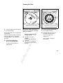
$GMXVWLQJ&DUEXUHWRU
Warm up the engine.
$WKLJKDOWLWXGH
Turn the high speed adjusting
screw + and low speed adjusting
screw / clockwise (leaner) or as
far as stop.
$WVHDOHYHO
Turn the high speed adjusting
screw + and low speed adjusting
screw / counterclockwise (richer)
or as far as stop.
e
p
r
i
n
t
Turn the idle speed
adjusting screw/$
clockwise until engine runs
smoothly - cutting
tool must not rotate.
&XWWLQJWRROURWDWHVZKHQ
HQJLQHLVLGOLQJ
Turn the idle speed adjusting
screw /$ counterclockwise until
cutting tool stops rotating then back off screw about
another one half turn from that
position.
-n
o
t
f
o
r
r
(QJLQHVWRSVZKLOHLGOLQJ
343BA046
343BA046
O
n
l
i
n
e
v
It is usually necessary to change
the setting of the idle speed
adjusting screw/$ after every
correction to the low speed
adjusting screw /.
e
r
s
i
o
n
$GMXVWLQJLGOHVSHHG
(UUDWLFLGOLQJEHKDYLRU
SRRUDFFHOHUDWLRQ
Idle setting is too lean.
Turn the low speed adjusting
screw/ counterclockwise until
engine runs and accelerates
smoothly.
000BA002 KN
&KHFNLQJ6SDUN3OXJ
Wrong fuel mix (too much engine oil in
the gasoline), a dirty air filter and unfavorable running conditions (mostly at
part throttle etc.) affect the condition of
the spark plug. These factors cause
deposits to form on the insulator nose
which may result in trouble in operation.
If engine is down on power, difficult to
start or runs poorly at idling speed,
first check the spark plug.
Remove spark plug see "If engine doesn’t start:"
Clean dirty spark plug.
Check electrode gap $ it should be 0.7 - 0.8 mm
(about 0.03") readjust if necessary.
•
•
•
e
p
r
i
n
t
343BA049
O
n
l
i
n
e
v
Use only suppressed spark plugs of
the approved type.
Rectify faults which have caused fouling
of spark plug:
Incorrect carburetor setting, too much oil
in fuel mix, dirty air filter, unfavorable
running conditions, e.g. operating at
part load.
)LWDQHZVSDUNSOXJDIWHU
DSSUR[RSHUDWLQJKRXUV
or earlier if the electrodes are
badly eroded.
Dirty air filters reduce engine power,
increase fuel consumption and make
starting more difficult.
,IWKHUHLVDQRWLFHDEOHORVV
RIHQJLQHSRZHU
•
•
Turn filter cover to
&+2.( to prevent dirt falling into the
carburetor.
Take out the screw and
pull off the filter cover without
turning it.
-n
o
t
f
o
r
r
•
e
r
s
i
o
n
•
•
•
343BA050
&OHDQLQJ$LU)LOWHU
Take the foam filter element out of the filter housing.
Wash the element in fresh, nonflammable cleaning solution
(e.g. warm soapy water)
and dry it off.
Always replace a damaged
filter element.
e
p
r
i
n
t
Fit the filter cover with the
choke lever in the closed
position - line up choke mark
on filter cover with . of &+2.(
on housing.
Secure cover with screw .
343BA052
343BA051
O
n
l
i
n
e
v
•
Install foam filter element .
e
r
s
i
o
n
•
•
If the engine is low on power, check the
spark arresting screen inside the muffler.
Slacken off but do not remove the
screws Pull out the spark arresting screen
from underneath the cover in the direction of the arrow (see
illustration).
•
•
Clean spark arresting screen if
necessary.
If screen is damaged or coked up,
fit a new one.
Refit the spark arresting screen.
Assemble in the reverse sequence.
-n
o
t
f
o
r
r
•
•
•
•
*Not all models
*HDUER[/XEULFDWLRQ
•
•
•
•
•
•
357BA050 KN
6SDUN$UUHVWLQJ6FUHHQLQ
0XIIOHU
Check grease level regularly
- about every 50 hours of
operation.
Unscrew the filler plug .
If no grease can be seen on the inside of the filler plug, screw the tube
of STIHL gear lubricant
0781 120 1117/1119 into the filler
hole.
Squeeze grease into the gear
housing - about 5 - 10 g (1/4 oz).
Do not completely fill the
gear housing with grease.
Refit the filler plug and tighten it
down firmly.
e
p
r
i
n
t
357BA051 KN
357BA052 KN
O
n
l
i
n
e
v
•
•
•
Pull the flexible shaft out
of the drive tube.
Use STIHL gear grease
0781 120 1109/1110 to coat dry areas of the shaft:
Do not apply too much grease never pump grease into the
drive tube.
If shaft has turned blue, fit a
new one.
-n
o
t
f
o
r
r
•
•
•
Check film of lubricant at
regular intervals every 50 hours of operation if you
use your brushcutter daily
or once a year if you use your
brushcutter occasionally.
Mark the end of the gear head on
the drive tube.
Release the clamp screws .
Pull the gear head off the
drive tube.
e
r
s
i
o
n
•
•
•
•
•
A
357BA054 KN
3
357BA053 KN
/XEULFDWLQJ)OH[LEOH6KDIW
Push shaft into the drive tube turn it to and fro until distance $is
less than 10mm (3/8").
Slide the drive tube into
the gear head turn drive shaft back and
forth until mark is reached.
Line up the gear head.
Tighten down the clamp screws.
e
p
r
i
n
t
Never straighten or weld a bent or
cracked grass cutting blade - it might
shatter and cause serious or fatal injury.
•
•
6KDUSHQFRUUHFWO\
If slightly dull:
Use flat file 0814 212 3310 In case of more serious wear or
nicks: Resharpen with a grinder maintain a sharpening angle of
30° $ on the cutting edge .
File back the cutting edge
parallel to the lines % (see
illustration).
Resharpen frequently, take
away as little material as
possible - two or three strokes
of the file are usually enough.
•
•
7RDYRLGRXWRIEDODQFH
Resharpen the cutters uniformly - do not alter the contour
of the parent blade in any way.
After resharpening about 5 times,
have blade checked on STIHL
balancer 5910 850 2600 and
rebalanced as necessary.
•
-n
o
t
f
o
r
r
•
Resharpen only when all cutting
edges on both sides of the
blade are dull: This ensures
balanced wear.
e
r
s
i
o
n
*UDVVFXWWLQJEODGH
357BA058 KN
357BA057 KN
357BA055 KN
O
n
l
i
n
e
v
357BA056 KN
6KDUSHQLQJ&XWWLQJ7RROV
*UDVVFXWWLQJEODGH
Never straighten or weld a bent or
cracked grass cutting blade - it might
shatter and cause serious or fatal injury.
•
•
•
Resharpen when the tips of the
cutting edges have worn
down to about 1mm/3/64" $.
7RDYRLGRXWRIEDODQFH
Resharpen the cutters uniformly - do not alter the contour
of the parent blade in any way.
After resharpening about 5 times,
have blade checked on STIHL
balancer 5910 850 2600 and
rebalanced as necessary.
e
p
r
i
n
t
357BA060 KN
357BA061 KN
O
n
l
i
n
e
v
357BA059 KN
2SHUDWLQJ,QVWUXFWLRQV
e
r
s
i
o
n
0HDVXUHPHQWVDQGDQJOHVIRU
UHVKDUSHQLQJ
6KDUSHQFRUUHFWO\
If slightly dull:
Use flat file 0814 212 3310 In case of more serious wear or
nicks: Resharpen with a grinder.
File back the cutting edge
parallel to the lines ( (see
illustration).
Resharpen frequently, take
away as little material as
possible - two or three strokes
of the file are usually enough.
•
•
•
-n
o
t
f
o
r
r
Leave clearance of 2mm/5/64" %
between cutting edge and parent
blade - 5should be 2mm/5/64".
Radius5is 2.5mm/7/64"and is
obtained automaticallyif you use
the specified file and maintain
a filing angle of 30° &.
Cutting edge ' must be exactly
in line with center of blade’s
mounting hole.
'XULQJEUHDNLQSHULRG
A factory new machine should not be
run at high revs (full throttle off load) for
the first three tank fillings. This avoids
unnecessary high loads during the
break-in period.
As all moving parts have to bed in
during the break-in period, the
frictional resistances in the engine
are greater during this period.
The engine develops its maximum
power after about 5 to 15 tank fillings.
'XULQJRSHUDWLRQ
After a long period of full-throttle
operation, allow engine to run for a while
e
p
r
i
n
t
6WRULQJWKH0DFKLQH
O
n
l
i
n
e
v
e
r
s
i
o
n
at idle speed so that the heat in the
engine can be dissipated by flow of
cooling air. This protects enginemounted components (ignition,
carburetor) from thermal overload.
$IWHUILQLVKLQJZRUN
Storing for an long period:
see chapter "Storing the Machine".
-n
o
t
f
o
r
r
Storing for a short period:
Wait for engine to cool down. To avoid
condensation, fill the fuell tank and
keep the unit in a dry place until you
need it again.
For periods of about 3 months or longer:
•
•
•
•
•
Drain and clean the fuel tank.
Run engine until carburetor is dry this helps prevent the carburetor
diaphragms sticking together.
Remove, clean and inspect the
cutting tool.
Thoroughly clean the machine pay special attention to the
cylinder fins and air filter.
Store the machine in a dry, high or
locked location - out of the reach
of children and other unauthorized
persons.
e
p
r
i
n
t
Throttle trigger, stop switch
Air filter
Replace
Check
Replace
Filter in fuel tank
Fuel tank
Clean
Carburetor
Check idle adjustment cutting tool must not turn
Cooling inlets
Inspect
Clean or replace
Spark arresting screen in muffler
All accessible screws and nuts
(not adjusting screws)
Retighten
Visual inspection
Replace
Sharpen metal cutting tools
Check tightness of cutting tool
Inspect
Cutting tool
Flexible shaft
x
x
x
-n
o
t
f
o
r
r
Lubricate
The user of the brushcutter may carry
out only the maintenance operations
described in this manual. Other repair
work may be performed only by an authorized STIHL Service Shop.
see page:
as required
if damaged
if faulty
monthly
weekly
after each
refueling stop
x
x
x
x
x
x
x
x
x
x
x
x
32-41
45
45
30
30
29
43-44
43-44
44
x
e
r
s
i
o
n
Clean
x
x
x
Readjust idle
Readjust electrode gap
Inspect
Spark plug
x
O
n
l
i
n
e
v
Visual inspection (condition, leaks)
Clean
Check operation
Clean
Complete machine
after finishing
work or daily
Please note that the following maintenance intervals apply for normal operating conditions.
If your daily working time is longer than normal or cutting conditions are difficult, shorten the specified intervals accordingly.
before
starting work
0DLQWHQDQFH&KDUW
:DUUDQW\FODLPVIROORZLQJUHSDLUVFDQ
EHDFFHSWHGRQO\LIWKHUHSDLUKDV
EHHQSHUIRUPHGE\DQDXWKRUL]HG
67,+/6HUYLFH6KRSXVLQJRULJLQDO
67,+/VSDUHSDUWV
x
x
x
x
x
46
46
x
x
x
x
x
x
x
23-28
23-28
48-49
23-28
47
47
Original STIHL parts can be identified by
the STlHL part number, the 67,+ logo
and the STIHL parts symbol The symbol may appear alone on small
parts.
e
p
r
i
n
t
6SHFLILFDWLRQV
(QJLQH
,JQLWLRQ6\VWHP
)XHO6\VWHP
Single cylinder two-stroke engine
Displacement:
30.2 cm3
(1.84 cu.in)
Bore:
34.8 mm
(1.36 cu.in)
Stroke:
31.8 mm
(1.25 in)
Engine power
to ISO 8893:
0.7 kW (0.95 bhp)
Max. engine speed: Speed limited by
control valve
Max. output
shaft speed
(tool mounting):
7 500 r.p.m.
Idle speed:
3 100 r.p.m.
Type:
Electronic (breakerless)
magneto ignition
Carburetor:
All position diaphragm carburetor
with integral fuel pump
Spark plug
(suppressed):
Air filter:
Foam element
Sound
pressure
level Lpeq
to
ISO 7917 1)
Sound
power
level Lweq
to
ISO 10884 1)
dB (A)
97
94
97
94
dB (A)
108
103
108
103
Vibration
acceleration
to
ISO 7916
Idle speed
(m/s2)
Handle
right
left
3.3
3.0
3.3
3.0
4.1
5.2
4.1
5.2
Average for idle speed and maximum engine speed with
equal periods of exposure
2)
Version with bike handle
3)
Version with loop handle
4)
Version with loop handle with standoff lever
O
n
l
i
n
e
v
1)
Mow. head
Metal tool
Mow. head
Metal tool
Fuel tank capacity:
0.51 l (1.08 US pt)
Fuel mixture:
see chapter “Fuel”
:HLJKW
without cutting tool
and deflector:
Vibration
acceleration
to
ISO 7916
Max. speed
(m/s2)
Handle
right
left
3.3
3.6
4.2
3.7
13.2
9.5
10.1
9.6
-n
o
t
f
o
r
r
FS 44 2)
FS 44 2)
FS 44 R 3)
FS 44 R 4)
Tool
Spark plug thread:
e
r
s
i
o
n
Model
Electrode gap:
GM AC CSR 45
or NGK BMR 6A;
Heat range 200
0.7 - 0.8 mm
(0.03 in)
M 14 x 1.25;
9.5 mm
(0.37 in) long
FS44 with bike handle
FS44 with loop handle
5.6 kg
(12.3 lb)
5.1 kg
(11.2 lb)
e
p
r
i
n
t
6SHFLDO$FFHVVRULHV
&XWWLQJ7RROV
1\ORQOLQHIRUFXWWLQJKHDGV
STIHL Supercut 20-2 mowing head
4002 710 2162
PPGLDPHWHUJUHHQ
15m/50ft
0000 930 2217
for 4
STIHL Autocut 24-2 mowing head
4002 710 2109
STIHL Autocut 20-2 mowing head
4002 710 2106
PPGLDPHWHUUHG
10.7m/35ft
0000 930 2218
for 7 and 8
STIHL Autocut 25-2 mowing head
4002 710 2108
STIHL Polymatic 30-2 mowing head
4002 710 2120
STIHL Polycut 20-3 mowing head
4002 710 2130
7KHUPRSODVWLFEODGHV
for 7
Pack of 12
4111 007 1001
e
r
s
i
o
n
7UDQVSRUWJXDUG
for 9 and 10
4119 790 3906
Grass cutting blade 230-4 4001 713 3801
2WKHUVSHFLDODFFHVVRULHV
Grass cutting blade 230-8 4001 713 3803
Shoulder strap
Full harness
Goggles
-n
o
t
f
o
r
r
STIHL Fixed Line Head
4001 713 2102
Not approved for FS 44 with
loop handle.
O
n
l
i
n
e
v
PPGLDPHWHURUDQJH
15m/50ft
0000 930 2243
for 1 to 8
STIHL gear grease
(80 g/3 oz tube) 0781 120 1109
(225 g/8 oz tube 0781 120 1110
STIHL gear lubricant
(80 g/3 oz tube) 0781 120 1117
(225 g/8 oz tube 0781 120 1119
e
p
r
i
n
t
67,+/,QFRUSRUDWHG)HGHUDODQG&DOLIRUQLD
(PLVVLRQ&RQWURO:DUUDQW\6WDWHPHQW
<RXU:DUUDQW\5LJKWV
DQG2EOLJDWLRQV
As the small off-road equipment engine
owner, you should be aware, however,
that STIHL Incorporated may deny you
warranty coverage if your small off-road
equipment engine or a part has failed
due to abuse, neglect, improper maintenance or unapproved modifications.
O
n
l
i
n
e
v
Your emission control system includes
parts such as the carburetor and the
ignition system. Also included may be
hoses, and connectors and other
emission related assemblies.
2ZQHU¶V:DUUDQW\5HVSRQVLELOLWLHV
As the small off-road equipment engine
owner, you are responsible for the performance of the required maintenance
listed in your owner’s manual. STIHL
Incorporated recommends that you
retain all receipts covering maintenance
on your small off-road equipment engine,
but STIHL Incorporated cannot deny
warranty solely for the lack of receipts or
for your failure to ensure the performance of all scheduled maintenance.
-n
o
t
f
o
r
r
STIHL Incorporated must warrant the
emission control system on your small
off-road engine for the period of time
listed below provided there has been no
abuse, neglect or improper maintenance
of your small off-road equipment engine.
0DQXIDFWXUHU¶V:DUUDQW\&RYHUDJH
The small off-road equipment engines
are warranted for two years in California.
In other states, 1997 and later model
year small off-road equipment engines
are also warranted for two years. If any
emission-related part on your engine is
defective, the part will be repaired or
replaced by STIHL Incorporated free of
charge.
e
r
s
i
o
n
The U.S. Environmental Protection
Agency (EPA), the California Air
Resources Board (CARB) and STIHL
Incorporated are pleased to explain the
Emission Control System Warranty on
your model year 2000 and later equipment type engine. In California, new
small off-road engines must be designed,
built and equipped to meet the State’s
stringent anti-smog standards. In other
states, new 1997 and later model year
small off-road equipment engines must
be designed, built and equipped, at the
time of sale, to meet the U.S. EPA
regulations for small non road engines.
The equipment engine must be free from
defects in materials and workmanship
which cause it to fail to conform with
U.S. EPA standards for the first two
years of engine use from the date of
sale to the ultimate purchaser.
Where a warrantable condition exists,
STIHL Incorporated will repair your small
off-road equipment engine at no cost to
you, including diagnosis (if the diagnostic
work is performed at an authorized
dealer), parts, and labor.
Any replacement part or service that is
equivalent in performance and durability
may be used in non-warranty maintenance or repairs, and shall not reduce the
warranty obligations of the engine
manufacturer.
You are responsible for presenting your
small off-road equipment engine to a
STIHL service center as soon as a
problem exists. The warranty repairs will
be completed in a reasonable amount of
time, not to exceed 30 days.
If you have any questions regarding
your warranty rights and responsibilities,
please contact a STIHL customer
service representative at 1-800-4678445 or you can write to STIHL Inc.,
536 Viking Drive, P.O. Box 2015,
Virginia Beach, VA 23450-2015.
&RYHUDJHE\67,+/,QFRUSRUDWHG
STIHL Incorporated warrants to the
ultimate purchaser and each subsequent
purchaser that your small off-road
equipment engine will be designed,
built and equipped, at the time of sale,
to meet all applicable regulations. STIHL
Incorporated also warrants to the initial
purchaser and each subsequent
purchaser that your engine is free from
defects in materials and workmanship
which cause the engine to fail to
conform with applicable regulations for a
period of two years.
e
p
r
i
n
t
0DLQWHQDQFH5HTXLUHPHQWV
The maintenance instructions in this
manual are based on the application of
the recommended 2-stroke fuel-oil
mixture (see also instruction "Fuel").
Deviations from this recommendation
regarding quality and mixing ratio of fuel
and oil may require shorter maintenance
intervals.
O
n
l
i
n
e
v
The California Air Resources Board’s
Emission Warranty Parts List specifically
defines the emission-related warranted
parts. These warranted parts are:
Carburetor
Choke (Cold start enrichment system)
Intake manifold
Air filter
Spark plug
Magneto or electronic ignition system
(ignition module)
Catalytic converter (if applicable)
Fasteners
-n
o
t
f
o
r
r
'LDJQRVLV
You, as the owner, shall not be charged
for diagnostic labor which leads to the
determination that a warranted part is
defective. However, if you claim warranty
for a component and the machine is
tested as non-defective, STIHL
Incorporated will charge you for the cost
of the emission test.
Mechanical diagnostic work will be
performed at an authorized STIHL
servicing dealer. Emission test may be
performed either at STIHL Incorporated
or at any independent test laboratory.
:DUUDQW\:RUN
STIHL Incorporated shall remedy
war-ranty defects at any authorized
STIHL servicing dealer or warranty
station. Any such work shall be free of
charge to the owner if it is determined
that a warranted part is defective. Any
manufacturer-approved or equivalent
replacement part may be used for any
warranty mainten-ance or repairs on
emission-related parts and must be
provided without charge to the owner.
STIHL Incorporated is liable for damages
to other engine components caused by
the failure of a warranted part still under
warranty.
e
r
s
i
o
n
:DUUDQW\3HULRG
The warranty periods will begin on the
date the utility equipment engine is
purchased by the initial purchaser and
you have signed and sent back the
warranty card to STIHL. If any emission
related part on your engine is defective,
the part will be replaced by STIHL
Incorporated at no cost to the owner.
Any warranted part which is not
scheduled for replacement as required
maintenance, or which is scheduled only
for regular inspection to the effect of
"repair or replace as necessary" will be
warranted for the warranty period.
Any warranted part which is scheduled
for replacement as required maintenance will be warranted for the period of
time up to the first scheduled replacement point for that part.
:KHUHWRPDNHDFODLPIRU:DUUDQW\
6HUYLFH
Bring the product to any authorized
STIHL servicing dealer and present the
signed warranty card.
/LPLWDWLRQV
This Emission Control Systems
Warranty shall not cover any of the
following:
- repair or replacement required
because of misuse, neglect or lack of
required maintenance,
- repairs improperly performed or
replacements not conforming to
STIHL Incorporated specifications
that adversely affect performance
and/or durability, and alterations or
modifications not recommended or
approved in writing by STIHL
Incorporated,
and
- replacement of parts and other
services and adjustments necessary
for required maintenance at and after
the first scheduled replacement point.
e
p
r
i
n
t