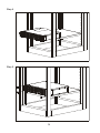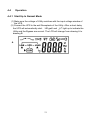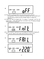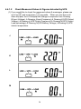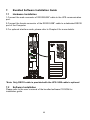
1
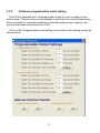
UniStar C Intelligent True On-Line UPS User Manual 1K/2K/3K Form No. 003-2308 Rev C Table of Contents 1 Important Safety Introduction ...................................................................3 An Important Notice.............................................................................3 Storage Instruction ............................................................................4 Product Introduction ............................................................................4 2.1 General Characteristics .......................................................................4 2.2 Special Features .................................................................................5 UPS Functiuonal Descriptions .............................................................6 3.1 UPS Front Panel Display Descriptions ................................................6 3.1.1 LED Panel (Standard) ........................................................................6 3.1.2 LCD Panel ...........................................................................................6 3.1.2.1 LCD Display.........................................................................................6 3.1.2.2 Symbols on the LCD Display Panel .....................................................7 3.2 Rear Panel Descriptions ....................................................................8 3.3 Operating Modes & Voltage System Configurations .........................10 3.3.1 System Configuration Settings ..........................................................10 3.3.2 Software Programmable Outlet Setting .............................................12 3.4 Communication Port Explanation ......................................................14 3.4.1 True RS232 Port Descriptions .........................................................14 3.4.2 USB Port Descriptions .......................................................................15 3.4.3 EPO ...................................................................................................15 Installation and Operation..................................................................16 4.1 Unpacking .........................................................................................16 4.2 Selecting Installation Position ..........................................................17 4.3 Set Up................................................................................................18 4.4 Operation .........................................................................................21 4.4.1 Start Up in Normal Mode ...................................................................21 4.4.1.1 Start-up in Battery Mode (Cold Start) ................................................23 4.4.1.2 Check Measured Values & Figures detected by UPS .......................24 4.4.1.3 UPS Default Data and Special Function Execution ...........................25 4.4.1.4 UPS Default Settings and Their Alternatives .....................................28 4.4.1.5 UPS Is Off Due To Unknown Reason and Trouble Shooting............29 4.4.1.6 Shut Off .............................................................................................30 4.4.2 Status & Audible Alarm .....................................................................30 4.4.3 Battery Replacement .........................................................................31 UPS Working Principle ......................................................................33 5.1 UPS System Block Diagram ..............................................................33 5.2 When Utility is Normal .......................................................................34 5.3 When Utility is Abnormal/Absent .......................................................35 5.4 Overload Condition ............................................................................36 5.5 Inverter Failure ..................................................................................37 5.6 Inverter/Internal Over Temperature ...................................................38 5.7 Inverter Over Current and Output Voltage Out Of Tolerance ............38 Maintenance Guide ...........................................................................39 1.1 1.2 2 3 4 5 6 1 6.1 6.2 6.3 7 7.1 7.2 8 8.1 8.2 8.2.1 9 Trouble Shooting ............................................................................... 39 Error Codes and their Descriptions ................................................... 39 Maintenance...................................................................................... 39 Bundled Software Installation Guide ................................................. 40 Hardware Installation ........................................................................ 40 Software Installation .......................................................................... 40 Dry Contact card SC-Relay (Optional) .............................................. 41 The Pin assignments of 10-Pin Terminal .......................................... 41 SNMP Card ..................................................................................... 42 SNMP/WEB Card SC-SNMPI (Optional) .......................................... 42 Specifications .................................................................................... 43 2 1. Important Safety Instruction 1.1 An Important Notice 1. Do not open the case, as there are no serviceable parts inside. Your Warranty will be void. 2. Do not try to repair the unit yourself; contact your local supplier or your warranty will be void. 3. If liquids are split onto the UPS or foreign objects dropped into the unit, the warranty will be null and void. 4. Do not install the UPS in an environment with sparks, smoke or gas. 5. This UPS is equipped with an EMI filter. To prevent potential leakage current hazard, ensure that the AC main supply is securely grounded. 6. This UPS is designed to be installed and commissioned in a sheltered, controlled environment as follows: - Operating temperature 0-40°C and 30-90% non-condensing humidity. - Always avoid contact with direct sunlight. - Do not install the UPS in a flammable or hazardous environment. - Dusty, corrosive and salty environments can do damage to any UPS. - Install the UPS indoors as it is not designed for installation outdoors. 7. To prevent any overheating of the UPS, keep all ventilation openings free from obstruction, and do not place anything on top of the UPS. Keep the UPS rear panel 20 cm away from the wall or other obstructions. 8. The battery will discharge naturally if the system is unused for any length of time. 9. Install the UPS away from objects that give off excessive heat and areas that are excessively wet. 10. Always switch off the UPS and disconnect the batteries when relocating the UPS. 11. The batteries should be recharged every 2-3 months if unused. If this is not done, then the warranty will be null and void. When installed and being used, the batteries will be automatically recharged and kept in top condition. 12 Make sure that the AC Utility outlet is correctly grounded. 13. Please ensure that the input voltage of the UPS matches the utility supply voltage. Use a certified input power cable with the correct plugs and sockets for the appropriate voltage system. 14. Intended for installation in a temperature-controlled, indoor area free of conductive contaminants. 15. Maximum ambient temperature 40°C 3 1.2 Storage Instruction For extended storage in moderate climate, the batteries should be charged for 12 hours every 3 months interval by connecting the UPS to the utility supply and switch on input breaker located at UPS rear panel. Repeat this procedure every 2 months if the storage ambient temperature is above 30 C. 2. Product Introduction 2.1 General Characteristics True online technology continuously supplies your critical device with a stable, regulated, transient-free pure sine wave AC Power. 1. High-efficiency PWM sine-wave topology yields an excellent overall performance. The high crest factor of the inverter handles all high inrush current loads without the need to upgrade the power rating. 2. User-friendly Plug-and-Play design allows hassle-free installation. All units up to 3Kva are supplied with input cables and output receptacles as standard. 3. Built-in Maintenance-free sealed-type batteries. 4. To protect the unit from overloading, the UPS will automatically switch to bypass mode in 30 seconds if loading is at 105%~ 120% of rated capacity. It will automatically switch back to inverter mode once overload condition ceases. 5. Should the output becomes short-circuited, the UPS will be locked automatically, then provide visual & audible alarm and cuts the output supply automatically till the short circuit situation is resolved manually. 4 2.2 Special Features 1. High Frequency Transformer-less technology with rack/tower convertible enclosure allows the UPS to be installed in the most difficult of environments with space constraints. 2. This UPS is equipped with digital control logic for greater functionality and enhanced high level power protection. Digital signal processing (DSP) also provides the UPS with powerful communication capability, which enhances the flexibility for easy remote control and monitoring 3. Wide input voltage tolerance from 60V ~ 144V (120V version) or 120V~288V (230V version) allows under-voltage or over-voltage correction without unnecessary battery drain and helps extend the battery life. 4. DC-start function allows start-up of the UPS during power outages. 5. Revolutionary battery management circuit analyzes battery discharging status to adjust battery cut-off point and extend battery life. 6. Active Power Factor Correction (PFC) control function constantly maintains the UPS Input Power Factor (PF) at > 0.99 for superb energy efficiency. 7. Software Selectable Bypass input voltage tolerance (Sensitivity low/high) to prevent under or over voltage being supplied to the load in Bypass mode. The selectable Voltage ranges are (i) Sensitivity: Low: 90/180~130/260V & (ii) Sensitivity High: 97/194~130/260V. 8. Software Selectable Output Voltages (100/110/115/120/127V on 120V models or 200/208/220/230/240) on 230V models to meet various voltage systems. 9. The UPS is designed to comply with various stringent international standards for Electromagnetic Interference & protection (EMC). 5 3. UPS Functional Descriptions 3.1 UPS Front Panel Display Descriptions 3.1.1 LCD panel LCD Display Green LED steadily lights up to indicate that the Utility input voltage is within the window (80Vac~144Vac, or 160Vac~288Vac); the LED flashes flickeringly to indicate that the Utility input voltage is within the acceptable window (60Vac~79Vac, or 120Vac~159Vac). 、 Green LED lights up to indicate there is an output available at the Programmable Outlet 1 & Programmable Outlet 2. Amber LED lights up to indicate the Bypass Input is normal. UPS Fault LED UPS On/Alarm Silence UPS OFF Switch 6 Special functions log in/out Go to next page Go to previous page or change the setting of the UPS. To confirm the change of UPS Setting ◎ Manual Bypass:Press" ON-KEY ” and " Up-KEY" key simultaneously for approx. 3 seconds to transfer from "Inverter to Bypass" (the bypass led continuously “blinks“ and audio alarm will beep intermediately) or "Bypass to Inverter", when the UPS is on Line Mode and the Bypass Voltage Window is Normal. 3.1.2.1 Symbols on the LCD Display Panel Item Symbol Description 1 LINE Utility or Bypass Source 2 Battery Low 3 Battery Abnormal 4 UPS Overloading 5 Site Wiring Fault 6 UPS Working in Service Mode 7 OFF UPS Shutoff 8 FAIL UPS Abnormal Lock 9 UPS Flow Chart 10 4 Digits Measurement Display 11 Indicate the item desired to be measured 22 23 24 25 26 27 Er05 Er06 Er10 Er11 Er12 Er** Battery Weak or Dead Output Short Circuit Inverter Over-current UPS Overheat UPS Output Overloading Other Error Code 7 3.2 Rear Panel Descriptions 120V 5 6 4 1KVA 1 2 3 8 10 2KVA 3KVA 8 7 230V 1KVA 2KVA 3KVA 1. USB Port 2. RS232 Port 3. Emergency Power Off (EPO) Dry Contact Signal inputs 4. Communication Card Options Slot 5. External Battery Connector 6. AC power connection socket 7. AC Outlets 8. Two programmable outlets 9. Utility Input circuit breaker 10. Cooling Fans 11. Output circuit breaker for two outlets 12. Output circuit breaker for two programmable outlets 9 3.3 Operating Modes & Voltage System Configurations Download and open the “UPS Setting Tool” Software to see the screen as below 3.3.1 System Configuration Settings 1. System Voltage Selection:Select Input Voltage 110V or 220V 2. Voltage Configurations:Select UPS Output Voltage 200V/208V/220V/230V/240V or 100V/110V/115V/120V/127V 3. UPS Modes:Select Normal/CF50*/CF60* Mode 4. Output Voltage Fine Tuning:Output Voltage Regulation from 0~±3% 10 5. Bypass Voltage Windows:Sensitivity: Select Sensitivity Low/Sensitivity High** Sensitivity Low Sensitivity High 120V System 90V~130V 97V~130V 230V System 180V~260V 194V~260V 6. Syn-Frequency Window:Select 3Hz/1Hz Inverter Freq synchronizing range 7. Com Port:Select the Com Port of PC 8. Click on “Write” to confirm the configuration settings. The UPS will beep twice to acknowledge setting is successful. 9. Turn off the UPS and unplug input power cord from AC Power Utility receptacle to shutdown whole unit without internal power supply existing, after setting is complete. 3 seconds later reconnect input power cord into AC Power Utility receptacle and turn on the UPS, referring to the section 4.4 Operation. The UPS will perform in new settings. Note: *CF50/CF60 = Frequency Converter mode 50 to 60Hz or 60 to 50Hz. When operating in CVCF mode the full load rating of the UPS is reduced to 75% (1000va becomes 750va). Additionally, the AC low transfer point based on load percentage is referred to the new power rating. 160Vac load rating is 66% ~ 100% (495va ~ 750va) 140Vac load rating is 33% ~ 66% 120Vac load rating is 0% ~ 33% **Sensitivity Low:90/180~130/260V, High: 97/194~130/260V 11 3.3.2 Software programmable outlet setting The UPS is equipped with 2 programmable outlets for use to supply to less critical loads. These outlets can be disabled to shed the less critical loads during back-up modes or overload conditions to maintain quality power supply to the more critical loads connected to the UPS. Click on the “Programmable outlet setting” bar to enter to the setting screen as shown below. 12 1. Outlet Turn On After UPS On– select the time to automatically enable this outlet within the specified time when the UPS is powered on. If “0” sec is selected, the outlet will be enabled once the UPS is powered on. 2. Outlet Turn Off After AC Failure – select this option to automatically disable the outlet within the specified time after utility outage to shed the less critical loads to provide longer battery back-up time for the other more critical loads connected to the UPS. 3. Outlet Turn On After AC Recovery – select this option to automatically enable the outlet within the specified time after the utility is restored. 4. Outlet Turn Off When Battery Low - select this option to automatically disable the outlet at the specified remaining battery power capacity(%) during battery mode to shed the less critical loads to prolong battery back-up time for the other more critical loads connected to the UPS. 5. Outlet Turn Off When UPS Overload – select this option to automatically disable the outlet during overload condition (bypass mode) to possibly allow the more critical loads: a) To be continually supplied via Bypass without shut down 6. You have to select the "Setting" menu to configure new parameters. The calibration is confirmed successfully after the UPS beeps twice. Turn off the UPS and unplug input power cord from AC Power Utility receptacle to shutdown whole unit without internal power supply existing, after setting is complete. 3 seconds later reconnect input power cord into AC Power Utility receptacle and turn on the UPS, referring to the section 4.4 Operation. The UPS will perform in new settings. 7. Manual Control Switch – Click “On” or “Off” to manually enabled or disabled the programmable outlets, overriding all previous settings. 13 3.4 Communication Port Explanation The UPS is equipped with EPO dry contacts input, true RS232 & USB Communication port as standard to provide communication with bundled UPS monitoring software for remote monitoring of UPS status via PC. There are 4 other optional interface cards available to meet various communication needs, i.e. DCE (dry contact relay card) 、R2E、USE and SNMP/WEB card (Please consult Chapter 8). The bundled software of the UPS is compatible with many operating systems such as Windows 98, & 2000, ME, NT, XP and Vista. For other applications such as Novell, NetWare, Unix, Linux, please contact your local dealer for suitable software. All the communication ports (including optional cards) can be active & used simultaneously to monitor the UPS status. However only 1 communication interface at any one time with the highest priority has the ability to command & control the UPS. The priority of these communication interfaces are as follow: Highest Priority (in descending order), 1) EPO input port 2) Optional Interface card 3) USB 4) RS232 3.4.1 True RS232 Port Descriptions The RS232 interface shall be set as follows: Baud Rate 2400 bps Data Length 8 bits Stop Bit 1 bit Parity None 14 The Pin Assignments of the true RS232 port are illustrated as follows: 5 4 3 2 1 9 8 7 6 3.4.2 Pin 3: RS232 Rx Pin 2: RS232 Tx Pin 5: Ground USB Port Descriptions The USB communication protocol definition as below: 1. Complies with USB version 1.0, 1.5Mbps 2. Complies with USB HID Version 1.0. 3. The Pin Assignments of the USB port: 1 VCC (+5V) 2 D- 3 D+ 4 Ground 3.4.3 EPO The Pin assignments of the EPO Input port are: 1 2 1 EPO+ 2 Ground To enable the EPO function, please short Pin 1 & 2. 15 4. Installation and Operation Read the Safety Instruction guide (page 2 to 3) before installing the UPS 4.1 Unpacking Inspect the UPS upon receipt. Staco has designed robust packaging for your product. However, accidents and damage may occur during shipment. Notify the forwarder and dealer if there is damage. The packaging is recyclable; save it for reuse or dispose of it properly. Remove the UPS from the carton box. Check the package contents. Standard content shall includes: 1 set of User's Manual 2 pcs of IEC output cables (for UPS with IEC sockets only) 1 pc of detached AC Input Power Cord (for UPS with IEC sockets only) 1 set of UPS communication software with RS232 cable 1 set of Tower/Rack Accessories Kit as below: 16 4.2 Selecting Installation Position The UPS is heavy. Select a location sturdy enough to handle the UPS weight. To ensure proper operation and long operating life, always position the UPS according to the following requirement: 1. Keep minimum 20cm (8 inches) distance clearance from the rear panel of the UPS to avoid any obstructions. 2. Do not block the air-flow to the ventilation louvers of the unit. 3. Please ensure the installation site is free from excessive dust and the ambient temperature and humidity should be within the specified limits. 4. Do not place the UPS in a dusty or corrosive environment or near any flammable objects. 5. This UPS is not designed for outdoor use. Relative humidity (non condensation) 17 0%~90% 4.3 Set up Tower Configuration Setup Step 1 Power Module + Battery Module Step 1 18 Rack-Mount Configuration Setup Step 1 Step 2 Step 3 19 Step 4 Step 5 20 4.4 Operation 4.4.1 Start Up In Normal Mode (1) Make sure the voltage of Utility matches with the input voltage window of the UPS. (2) Connect the UPS to the wall Receptacle of the Utility. After a short delay the UPS will automatically start. LED and light up to indicate the Utility and the Bypass are normal. The LCD will change from drawing A to drawing B. A 21 B (3) The UPS is on Bypass Mode now and will proceed to self-test automatically. If there is no abnormal message then the pre-start-up of the UPS was successful and the charger begins to charge the batteries. (4) Press the UPS On Switch„ ‟for approx. 3 seconds, until the unit beeps twice. If the UPS start-up is successful, the LCD display changes from drawing B to drawing C. C (5) In case of failure in self-test, the LCD display will illustrate as drawing D, then, an error code or error status will be shown on the screen. D E 22 (6) The start-up sequence of the UPS is complete as illustrated as drawing E. Make sure the UPS is plugged onto the wall receptacle for at least 8 hours to ensure the batteries are fully charged. To turn off the UPS press and hold the Off switch until the alarm beeps twice, then release the switch. The UPS will shut down a few seconds later. 4.4.1.1 Start-up in Battery Mode (Cold Start) (1) Make sure the UPS has fully charged batteries installed. (2) Press the UPS On switch for approx. 3 seconds until the audible alarm sounds twice, then release the On switch. The LCD display will change from Drawing A to drawing G. G (3) Press the UPS On switch of the UPS a second time for approx. 3 seconds until the audible alarm sounds twice, then release the On switch. Failure to press the On switch a second time within 10seconds will cause the UPS to shut off. The LCD display changes from drawing G to drawing H, then the UPS will be in self-test Mode. The Inverter will supply voltage to the output within 1 minute, and the LCD display changes to drawing I. H I 23 4.4.1.2 Check Measured Values & Figures detected by UPS (1) If you would like to check the measured values & messages, please use scroll up and scroll down key pads. When you use the scroll down key pad, the LCD display will change in sequence from Drawing E(Input Voltage) Drawing J(Input Frequency) Drawing K(UPS Output Voltage) Drawing L(UPS Output Frequency) Drawing M(UPS Output Load percentage) Drawing N(UPS Battery Voltage) Drawing O(UPS interior temperature. J K L M 24 N O 4.4.1.3 UPS Default Data and Special Function Execution (1) After UPS is turned on successfully, use Display screen to drawing P1. key pad to change the LCD P1 P2 (2) Press key pad to scroll down the LCD screen, then check the UPS settings. The LCD display will show in sequence: Drawing P1(audible alarm)Drawing Q1(self test)Drawing R1(Bypass Voltage)Drawing S(Output Frequency Synchronized Window)Drawing T(Inverter Output Voltage)Drawing U1(UPS Operation Mode)Drawing V(Output Voltage Fine Tuning) 25 Q1 Q2 R1 R2 S 26 T U1 U2 U3 V 27 (3) Press scroll up key pad, you may execute special functions. The functions include Buzzer ON (as drawing P1) or buzzer OFF (as drawing P2, Alarm silence for UPS warning) and self-test ON (as Drawing Q1) or OFF (as Drawing Q2. UPS will execute battery test for 10 seconds), if the self-test is successful, it show as Drawing W; otherwise, it will show as Drawing D & error message at the same time. W 4.4.1.4 UPS Default Settings and Their Alternatives (1) Begin with the UPS Off and disconnected from the utility. Connect the UPS to the utility and immediately proceed with the following, before the UPS starts to self test. Make sure the UPS is not “ON” yet, which means it is not in Line Mode or Backup Mode. Press the ON Switch and scroll down key pads simultaneously for approx. 3 seconds, the audible alarm will sound twice, the LCD display screen displays as drawing P1. The UPS is now in setup mode. (2) To scroll down the LCD screen press the scroll down key pad. (3) Except audible alarm (as Drawing P1 & P2) and self-test (Q1 & Q2), all of the default settings may be changed by pressing scroll up key pad. (4) Use caution if adjusting the bypass input acceptable window. It can be 180Vac~ 260Vac for 220Vac system, 90Vac~130Vac for 110Vac system or 194Vac~260Vac for 220Vac system, 97Vac~130Vac for 110Vac system. (5) Drawing S indicates the bypass frequency window of the inverter output. The acceptable setting values are +/-3Hz and +/-1Hz. (6) Drawing T indicates the acceptable Inverter Output Voltage, of which voltage is 200V, 208V, 220V, 230V, or 240V for 220Vac system , or 100V, 110V, 115V, 120V and 127V. (7) Drawings U1, U2 and U3 indicate the operating modes of the UPS, of which the alternatives are Online, fixed 50Hz Output or fixed 60Hz Output. (8) Drawing V indicates the adjustments of the Inverter Output, which may be calibrated as 0%, +1%, -1%, +2%, -2%, +3%, or -3%。 (9) When all the setting changes are done, you have to save the changes. Press the scroll down key pad until the display show as drawing X. Now press the enter key pad to save all the changes. The changes will be activated only when the UPS is re-started. 28 X (10) Turn off the UPS and disconnect from the Utility. (11) Your Setting changes are complete. 4.4.1.5 UPS Is Off Due to Unknown Reason and Trouble Shooting (1) If there is a serious abnormal condition occurred, the UPS will lock itself as shown in the drawing Y and a abnormal message will show in the LCD screen. Y (2) In most of abnormal conditions occur, the UPS remains bypass output; however, when it is out of bypass window set, the UPS will be locked and the abnormal status will be shown as drawing Z on the LCD screen. Z (3) To release the UPS lock, proceed as follows: (a) Check those error messages recorded (b) See Chapter 6.2 to trouble shoot the problem. Otherwise, consult your local distributor for service. (c) Press key pad for 5 seconds and the audible alarm will sound twice. (d) Disconnect the UPS from the Utility Input. (e) The UPS lock problem is now cleared. 29 4.4.1.6 Shut Off (1) Press key pad for about 5 seconds, the Inverter output will be turned off, the output load is supplied by Bypass loop and the LCD screen displays as drawing B. (2) Disconnect the UPS from the utility. (3) The UPS is turned off completely. 4.4.2 Status & Audible Alarm The following table helps to define some of the common UPS statuses with respect to their audible alarm descriptions. Status Definitions UPS faulty, Inverter shutdown. All functions inhabited. UPS faulty, loads continue to be supplied via Inverter or Bypass. battery mode battery low confirm/RS232 port receiving service mode ok UPS initial start-up with self test Audible Alarm Descriptions Long Continuous Beep Single successive beep with ~ 2 sec interval Single short successive beep with ~1 sec interval Very quick and short successive beep 2 quick & short beeps 1 quick & short beep 2 successive quick & short beeps, repeating per ~2 sec interval. 30 4.4.3 Battery Replacement Step 1 Step 2 31 Step 3 Step 4 1KVA 2K/3KVA 32 5. UPS Working Principle 5.1. UPS System Block Diagram (fig 5.1) Figure 5.1 above illustrates the True On-Line Double Conversion architecture of the UPS system. The major modules consist of: 1) An AC to DC power converter (Rectifier) with PFC control circuit 2) A DC to AC power high frequency inverter 3) An Intelligent Battery Charger 4) A bank of stationary maintenance-free batteries 5) A DC to DC push/pull converter control circuit 6) A Static Bypass Loop 7) Input & Output EMI Filter The table below provides a summery guide to the UPS operating modes against the Utility AC Power Source conditions 33 Utility Conditions UPS Operating Modes LEDs Display indications Utility Normal Rectifier convert AC to DC, battery charging, Inverter convert DC to AC , , LEDs and supply to loads with clean & stable remain illuminated power. Utility Abnormal (under or over voltage) / Absent Rectifier and charger stop operating, Battery discharge via DC~DC boost LED off, circuit and supply to Inverter. Loads illuminated continue to receive supply from Inverter. Alarm beeps, UPS now on battery mode. Utility Abnormal/Absent, Battery low voltage Rectifier and charger stop operating, Battery discharge via DC~DC boost LED off, & circuit and supply to Inverter. Alarm LED illuminated. beeps with quick & short succession, indicating battery power low and Inverter may stop supply soon. LED Paragraph 5.2 ~ 5.7 below provide detailed descriptions of the UPS operating principle 5.2 When Utility is Normal The working principle of the UPS under Utility normal condition is illustrated as follows: Fig 5.2 When Utility is normal, the AC source is rectified to DC, which fed into the inverter. The charger will turn on automatically to charge batteries. The inverter revert the DC to a cleaned and pure AC to supply energy to the load connected. The , , LEDs illuminated. 34 5.3 When Utility is Abnormal/Absent The working principle of the UPS under Utility abnormal condition is illustrated as follows: Fig 5.3 1. When Utility is abnormal, the UPS will direct the battery energy automatically to the Inverter without delay, and turn off the charger and AC/DC converter. The inverter converts the DC to AC to supply energy to the output connected load without interruption. The LED will be illuminated. 2. When Utility is back to Normal, the UPS will turn on the AC/DC converter, turn off the DC/DC converter and switch the charger to charging mode. It has the same working principle as figure 5.2. 3. During a utility outage, the UPS will work as illustrated in figure 5.2. When Battery is low, the audible alarm will beep continuously until the battery reaches low battery cut off. The battery low protection of the UPS will cut off battery supply after a preset threshold to avoid the battery from over-drain. The & (Battery Low) LED‟s will light up until the UPS is completely cut off. The UPS will re-start automatically when Utility is available. 35 5.4 Overload Condition The working principle of the UPS when overloading is illustrated as follows: (1) Generally, modern electronics & IT equipment generate an inrush current when switching on. The amount of inrush current varies from equipment to equipment, some can be as high as 6 times its rated capacity while others produce negligible inrush. To prevent severe damage to the Inverter, caused by inrush produced by loads, the UPS is equipped with an electronic overload protection feature. If the UPS load is >105~120% of its capacity, it will switch to bypass mode in 30 seconds to protect the Inverter. If the overload condition is eliminated by reducing the load to <105%, the UPS will switch back to Inverter mode automatically. If the UPS is over 150% loading, it inverter will shutdown immediately. 36 2. The UPS Bypass loop is also equipped with overload protection. Its overload capacity is illustrated by the graph & table below. 5.5 Inverter Failure Output Load short circuit when being supplied from inverter If the output load is shorted while being supplied by the Inverter, the UPS will shutdown the Inverter automatically. The Fault LED lights up and the audio alarm beeps continuously. The UPS will not switch on automatically after a short circuit condition is eliminated. The UPS has to be re-start manually (refer to 4.4.1 „Start Up in Normal Mode‟). Fig 5.5 37 5.6 Inverter/Internal Over temperature If the UPS experiences internal over-temperature while the Utility is normal, it will switch to bypass loop. The UPS will switch back to inverter mode when the overtemperature situation is eliminated. If over temperature occurs when Utility is abnormal, it will beep continuously and the Fault LED will light up. The UPS will cut off supply to the loads. 5.7 Inverter Over Current and Inverter Output Voltage Out of Tolerance If the UPS inverter delivers over-current and out-of-tolerance voltage to its outlets, the UPS has failed. The UPS will switch to bypass loop when Utility is normal. The Utility LED, Bypass LED and Fault LED will light up. If these two fault conditions occur when Utility is abnormal, the UPS will cut off the supply to its outlets and the Fault LED will light up. 38 6. Maintenance Guide 6.1 Trouble Shooting When the UPS becomes faulty or malfunctions during operation, you may check the fault lists below for possible solutions. Should the problem persist, please contact Staco for assistance. 6.2 6.3 Error Codes and Their Descriptions Code Descriptions Er05 Battery weak or faulty Er06 Output short-circuited Er07 Er11 Er12 EPO mode UPS over-temperature Inverter overload Er14 Fans out of order Er18 EEPROM's data error Er24 Utility Low(<85/170V)& Battery Disconnect Er28 Bypass overload Er31 EEPROM's data not conform to the Jumper Setting Maintenance Clean the dust from the ventilation openings and intakes on the rear panel. 1. Turn off the UPS and wipe the casing with a damp cloth. 2. Periodically unplug the power cord of the UPS from the wall receptacle to test the batteries condition. 3. Be sure you have already saved your application before you proceed to the battery discharging capability test. 39 7. Bundled Software Installation Guide 7.1 Hardware Installation 1.Connect the male connector of RS232/USB* cable to the UPS communication port. 2.Connect the female connector of the RS232/USB* cable to a dedicated RS232 port of the Computer. 3.For optional interface cards, please refer to Chapter 8 for more details. EPO G DC 36V 1 2 AC OUTPUT *Note: Only RS232 cable is provided with the UPS. USB cable is optional 7.2 Software Installation Please refer to the user‟s manual of the bundled software CD ROM for installation guide. 40 8. 8.1 Dry Contact card SC-Relay (Optional) The pin assignments of 10-Pin Terminal: 1 2 3 4 4 5 6 7 8 9 10 1 UPS on Bypass mode (Bypass) 2 Utility Normal (Normal close contact) 3 Utility Normal (Normal open contact) 4 Inverter On 5 Battery Low 6 Battery Bad or abnormal 7 UPS Alarm 8 Common 9 Shutdown UPS positive(+) signal 10 Shutdown UPS negative(-) signal The shutdown function will be activeated, after a +6~+25Vdc is put between pin 9 and pin 10 for 5 seconds. The capacity of each relay contact is 40Vdc/25mA. Installation Position:Optional Slot. Flexible signal output for N.C.(Normal Close) or N.O.(Normal Open) contact by shorting pin1-2 or pin2-3 form JP1-5. The shutdown function will be enabled 1 minute after a blackout occurs if pins 1-2 of both CN1 and CN6 are shorted. Or, the shutdown function can only be enabled by pin9-10 of CN3 if the pin2-3 of both CN1 and CN6 are shorted. 41 8.2 SNMP Card 8.2.1 SNMP/WEB card SC-SNMPI (Optional) For installation, please refer to the user‟s manual attached with the card. Installation Position:Option slot 42 9. Specifications Model 1KVA 2KVA 3KVA 1000VA 2000VA 3000VA 700Watts 1400Watts 2100Watts VA Rating Apparent Output Power Active Output Power Power Factor 0.7 Topology Double conversion On-Line Type Rack/Tower 120V Models: UL, cUL, FCC 230V Models: CE Agency Approvals Input Voltage Window 120V 230V 60/70/80 - 144Vac 120/140/160 - 288Vac Based on load percentage (0~33/33~66/66~100%) Low Line Transfer Voltage Range Low Line Comeback High Line Transfer High Line Comeback 120V 230V 120V 230V 120V 230V 120V 230V 60/70/80Vac 120/140/160Vac 85Vac 170Vac 144Vac 288Vac 139Vac 278Vac Frequency 50/60 Hz auto-select, ± 5Hz Phase Single phase with ground PF >0.99 at full rated linear load 0 ms. Typical Transfer Time AC Leakage current Surge Protection 115V 5mA 230V 3.5mA 115V 230V 400 joules 300 joules 120V 230V 120V,software adjustable to 100/110/115/120/127 230V,software adjustable to 200/208/220/230/240 Output Voltage Voltage Regulation Output (INV. mode) Frequency(Synchroniz ed Range) Frequency(Battery Mode) 1% until low battery warning 3Hz or 1Hz (setting by software) ±0.1% (0.05~0.06Hz) unless synchronized to line 43 Current Crest Factor 3:1 Harmonic Distortion ≦ 3% THD(Linear Load) ≦ 7% THD(Non-Linear Load) Transient Response(ms) <=60ms/5% Waveform Efficiency Pure Sine wave To AC Mode (Full load) 85% 85% 88% To Battery Mode (Full load) 83% 83% 85% 12V/7.2Ah 12V/7.2Ah 12V/9Ah 3 6 6 >7min. >7min. >5min. Battery System Type Numbers of Batteries Backup Time(Full Load) Recharging Time Charging Current (Max.) Charging Voltage 4 Hours to 90% 1.1A 2.16A 2.7A 41.0Vdc±0.5V 82.0Vdc±0.5V 82.0Vdc±0.5V Yes Hot Swappable Battery Yes Internal battery DC leakage current Battery type 30uA ( 10uA) with no AC applied and the unit in the off position Sealed, non-spill, maintenance-free, lead acid Transfer Time AC to DC Inverter to Bypass Zero 2.5ms(Typical) DC Start Self Diagnostics Zero Yes By button of the front panel or Software Control Front Panel LCD Load Level/Battery Level/ Battery Mode/ Normal Mode/Bypass Mode/ Self-Test/ Weak/Bad Battery/Site Wiring Fault/ Fault/ Overload/Programmable Outlet1//Programmable Outlet2 Key ON Button/ OFF Button/ (Test/Alarm Reset Button) Protection Overload (AC Mode ) <105% continuous >106%~120% for 30 seconds transfer to bypass >121%~150% for 10 seconds transfer to bypass >150% for immediately transfer to bypass * Notification: continuous alarm. 44 (Battery Mode) <105% continuous >106%~120% for 30 seconds shuts down >121%~150% for 10 seconds shuts down >150% for immediately shuts down * Notification: continuous alarm. (Bypass Mode) <105% continuous >106%~120% for 250 seconds shuts down >121%~130% for 125 seconds shuts down >131%~135% for 50 seconds shuts down >136%~145% for 20 seconds shuts down >146%~148% for 5 seconds shuts down >149%~157% for 2 seconds shuts down >158%~176% for 1 seconds shuts down >177%~187% for 0.32 seconds shuts down >188% for 0.16 seconds shuts down * Notification: continuous alarm. Bypass mode : Input Fuse/Input Breaker Normal Mode: Output Breaker/Electronic Circuit Battery Mode: Output Breaker/Electronic Circuit Short Circuit Battery ABDM EPO - Standard Over Temperature UPS shuts down immediately Normal Mode Transfer to Bypass Mode Battery Mode UPS shuts down immediately Audible Alarm Battery Mode Sounding once every 1.5 seconds Low Battery Sounding once every 0.2 seconds Overload Sounding once every 3 second Fault Continuously Sounding(or Sounding once every 3 second) Physical Dimensions(HxWxD in/mm) 3.5/89x17.3/440x 25.6”/650 3.5/89x17.3/440x 25.6/650 34.5Ib(15.7kg) 64.7Ib(29.4kg) 65.3Ib(29.7kg) 120V 230V NEMA 5-15P 10A, IEC 320-C14 120V (6) 5-15R NEMA 5-20P 10A, IEC 320-C14 (2) 5-15R (2) 5-20R NEMA L5-30P 16A, IEC 320-C20 (4) 5-15R (1) L5-30R (4) 10A,IEC 320-C13 (1) 16A,IEC 320-C19 Weights Input Connection 3.5/89x17.3/440x 16/406 Output Connection 230V (6) 10A,IEC 320-C13 Environmental Operation Temperature 0-40°C 45 <50dBA Noise Level Relative Humidity 0 to 90% (Without condensation) Interface Interface Type -Standard SNMP (Optional) Compatible platforms 1 *USB port+ 1*RS-232 port Power management from SNMP manager and Web browser Windows 95/98/NT/2000/XP/Vista Novell NetWare, Linux, etc. Standards and Certification Safety Performance EMC IEC/EN 62040-1-1,IEC 60950-1 IEC/EN 62040-3 IEC/EN62040-2 Class A, FCC Part 15 Subpart B Class A, IEC/EN55011, CISPR11, IEC61000-4-2/-3/-4/-5, IEC61000-2-2, IEC61000-3-2/-3 Markings CE, UL, cUL, FCC 46