1
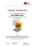
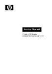
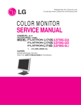
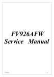
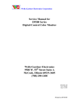
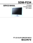
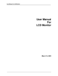
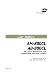
COLOR MONITOR
SERVICE MANUAL
MODEL: SDM-HS73P
( U/C AEP CH Model )
CAUTION
BEFORE SERVICING THE UNIT,
READ THE SAFETY PRECAUTIONS IN THIS MANUAL.
OK
MENU
CONTENTS
SPECIFICATIONS ................................................... 2
PRECAUTIONS ....................................................... 3
TIMING CHART ........................................................4
OPERATING INSTRUCTIONS ................................ 5
WIRING DIAGRAM ................................................. 6
BLOCK DIAGRAM ................................................... 7
ADJUSTMENT ...................................................... 8
EXPLODED VIEW.................................................. 9
ACCESSORIES & PACKING MATERIALS............ 10
SPECIFICATIONS
1. LCD CHARACTERISTICS
Type
: TFT Color LCD Module
Active Display Area : 17 inch(337.92(H) x 270.336(V))
Size
: 358.5(W) x 296.5(H) x 19.5(D)
Pixel Pitch
: 0.264 (Per one triad) x 0.264
Color Depth
: 16.2M Colors
Electrical Interface
: LVDS
Operating Mode
: Normally White
Backlight Unit
: 4-CCFL (Cold Cathode
Fluorescent Lamp)
2. OPTICAL CHARACTERISTICS
2-1. Viewing Angle by Contrast Ratio ≥ 10
Left : -60° min., -70°(Typ) Right : +60° min., +70°(Typ)
Top :+60° min., +70°(Typ) Bottom : -60°min., -70°(Typ)
2-2. Luminance
: 350(min), 400(Typ)
2-3. Contrast Ratio
: 250(min), 450(Typ)
5. POWER SUPPLY
5-1. Power : AC 100~240V, 50/60Hz , 1.0A
5-2. Power Consumption
MODE
: R, G, B Analog
: 0~0.70 V( 5%)
: 0 Vp-p
: 0.35 Vp-p
: 0.7 Vp-p
: 75 Ω
ON/ON
ACTIVE
less than 45 W
GREEN
STAND-BY
OFF/ON
OFF
less than 1 W
AMBER
SUSPEND
ON/OFF
OFF
less than 1 W
AMBER
DPMS OFF
OFF/OFF
OFF
less than 1 W
AMBER
POWER S/W OFF
-
-
less than 1 W
OFF
6-1. Operating Temperature: 5°C~35°C (41°F~95°F)
(Ambient)
6-2. Relative Humidity
: 10%~80%
(Non-condensing)
6-3. MTBF
: 50,000 Hours(Typ)
30,000 Hours(Min)
7. DIMENSIONS (with TILT/SWIVEL)
Width
Depth
Height
: 441 mm (17.36'')
: 216 mm (8.50'')
: 404 mm (15.90'')
8. WEIGHT (with TILT/SWIVEL)
Net. Weight
Gross Weight
3-3. Operating Frequency
Horizontal
: 28 ~ 80kHz
Vertical
: 48 ~ 75Hz
4. Max. Resolution
Analog
POWER ON (NORMAL)
6. ENVIRONMENT
3. SIGNAL (Refer to the Timing Chart)
3-1. Sync Signal
• Type
: Separate Sync
3-2. Video Input Signal
1) Type
2) Voltage Level
a) Color 0, 0
b) Color 7, 0
c) Color 15, 0
3) Input Impedance
H/V SYNC VIDEO POWER CONSUMPTION LED COLOR
: 1280 x 1024 / 75Hz
-2-
: 6.0 kg (13.23 lbs)
: 8.1 kg (18.86 lbs)
PRECAUTION
WARNING FOR THE SAFETY-RELATED COMPONENT.
WARNING
• There are some special components used in LCD
monitor that are important for safety. These parts are
marked on the schematic diagram and the
replacement parts list. It is essential that these critical
parts should be replaced with the manufacturer’s
specified parts to prevent electric shock, fire or other
hazard.
• Do not modify original design without obtaining written
permission from manufacturer or you will void the
original parts and labor guarantee.
TAKE CARE DURING HANDLING THE LCD MODULE
WITH BACKLIGHT UNIT.
• Must mount the module using mounting holes arranged
in four corners.
• Do not press on the panel, edge of the frame strongly
or electric shock as this will result in damage to the
screen.
• Do not scratch or press on the panel with any sharp
objects, such as pencil or pen as this may result in
damage to the panel.
• Protect the module from the ESD as it may damage the
electronic circuit (C-MOS).
• Make certain that treatment person’s body are
grounded through wrist band.
• Do not leave the module in high temperature and in
areas of high humidity for a long time.
• The module not be exposed to the direct sunlight.
• Avoid contact with water as it may a short circuit within
the module.
• If the surface of panel become dirty, please wipe it off
with a softmaterial. (Cleaning with a dirty or rough cloth
may damage the panel.)
CAUTION
Please use only a plastic screwdriver to protect yourself
from shock hazard during service operation.
-3-
BE CAREFUL ELECTRIC SHOCK !
• If you want to replace with the new backlight (CCFL) or
inverter circuit, must disconnect the AC adapter
because high voltage appears at inverter circuit about
650Vrms.
• Handle with care wires or connectors of the inverter
circuit. If the wires are pressed cause short and may
burn or take fire.
TIMING CHART
<< Dot Clock (MHz), Horizontal Frequency (kHz), Vertical Frequency (Hz), Horizontal etc... (µs), Vertical etc... (ms) >>
Mode
1
2
3
4
5
6
7
8
9
10
11
12
13
14
15
16
17
18
19
20
21
22
H/V
Sort
Sync
Polarity
H
–
V
+
H
–
V
–
H
–
V
H
–
–
V
–
H
–
V
–
H
+-
V
+
H
+
V
+
H
+
V
+
H
+
V
+
H
–
V
–
H
–
V
–
H
–
V
–
H
+
V
+
H
–
V
–
H
+
V
+
H
–
V
–
H
–
V
–
H
–
V
–
H
+
V
+
H
+
V
+
H
+
V
+
H
+
V
+
Dot
Clock
28.350
25.175
30.240
31.500
31.505
36.000
40.000
50.000
49.500
57.285
65.000
75.000
78.750
80.000
108.000
100.000
92.940
105.590
46.200
108.000
108.000
135.000
Frequency
Total Period Video Active Time Front Porch Sync Duration
(E)
(A)
(C)
(D)
18
108
Back Porch
(F)
Blanking time
(B)
Resolution
54
180
720x400
70Hz
31.500
900
720
70.156Hz
449
400
12
3
34
49
31.469
800
640
16
96
48
160
59.940Hz
525
480
10
2
33
45
35.00
864
640
64
64
96
224
66.667Hz
37.50
525
840
480
640
3
16
3
64
39
120
45
200
75.0Hz
500
480
1
3
16
20
35.162
896
720
34
40
102
176
59.901Hz
587
480
12
2
93
107
35.156
1024
800
24
72
128
224
56.250Hz
625
600
1
2
22
25
37.879
1056
800
40
128
88
256
60.317Hz
628
600
1
4
23
28
48.077
1040
800
56
120
64
240
72.188Hz
666
600
37
6
23
66
640x480
60Hz
640x480
65Hz
640x480
75Hz
720x480
60Hz
800x600
56Hz
800x600
60Hz
800x600
72Hz
46.875
1056
800
16
80
160
256
75.0Hz
625
600
1
3
21
25
800x600
75Hz
49.727
1152
832
32
64
224
320
832x624
74.553Hz
667
624
3
3
37
43
75Hz
48.363
1344
1024
24
136
160
320
1024x768
60Hz
60.004Hz
806
768
3
6
29
38
56.476
1328
1024
24
136
144
304
70.069Hz
806
768
3
6
29
38
60.023
1312
1024
16
96
176
288
(MAC16”)
1024x768
70Hz
75.029Hz
800
768
1
3
28
32
1024x768
75Hz
60.241
1328
1024
32
96
176
304
1024x768
74.927Hz
804
768
3
3
30
36
75Hz
67.500
1600
1152
64
128
256
448
(MAC19)
75.000Hz
900
864
1
3
32
36
1152x864
75Hz
68.681
1456
1152
32
128
144
304
1152x870
75.062Hz
915
870
3
3
39
45
75Hz
1152x900
66Hz
61.795
1504
1152
30
128
194
352
65.950Hz
937
900
2
4
31
37
71.732
1472
1152
16
96
208
320
76.068Hz
943
900
2
8
33
43
31.216
1480
1170
37
129
144
310
50.026Hz
624
584
3
3
34
40
60.000
1800
1280
96
112
312
520
60.000Hz
1000
960
1
3
36
40
63.981
1688
1280
48
112
248
408
60.020Hz
1066
1024
1
3
38
42
79.976
1688
1280
16
144
248
408
75.025Hz
1066
1024
1
3
38
42
-4-
(MAC21)
1152x900
75Hz
1170x584
50Hz
1280x960
60Hz
1280x1024
60Hz
1280x1024
75Hz
TIMING CHART
VIDEO
B
A
E
C
D
SYNC
F
OPERATING INSTRUCTIONS
REAR VIEW
FRONT VIEW
NY
SO
D-Sub Signal
Connector
OK
MENU
See front control panel
Power Connector
Front Control Panel
MENU
OK
5
1. Power switch and indicator
This switch turns the dislay on and off.
This power indicator lights up in green when the
display is turned on, and lights up in orange when
the monitor is in power saving mode.
3
2
1
4. OK Button
This button select the item or executes the settings
in the menu.
5.
2. MENU Button
This button display or close the main menu.
3.
4
Buttons
These buttons function as the
buttons when
selecting the menu items and making adjustments.
-5-
Button(Backlight control)
WIRING DIAGRAM
Connector Ass’y
P/N: 190027329
J705
J702
GENESS
CN4
CN2
J710
CN1
CN3
-6-
AC Input
AVD D2.5V
DVDD2.5V
AVD D3.3V
DVDD3.3V
-7-
LIPS
5V
2.5V
Reg.
3.3V
Reg.
12V
5V
5V
AVD D 2.5V
DVDD 2.5V
AVD D 3.3V
DVDD 3.3V
5V
D-SUB
R,G,B, H/V Sync
(MCU/ADC /LVDS )
Data 8 Bit
Address
LVDS
(Low Voltage
Differential Signaling)
GM2121
including
R,G,B
differential
LCD Module
Flash
Memory
BLOCK DIAGRAM
ADJUSTMENT
1. Procedures of how to go to service mode.
3. Operation
1) Enter the service mode of this unit by turning on the
power while pressing and holding the " " key
simultaneously.
2) Press "MENU" key----MAINTAIN.
3) Press "OK" key to enter the service menu.
4) Select the desired function.
5) Press the "MENU" key to exit OSD.
6) Turn off the power and then turn on it again. The
monitor then enters the normal mode.
To enter the service again, repeat the procedure
described above.
Data is manually set to improve the productivity. The
brightness, contrast, and backlight are set to 50, 70
and 100 respectively. After that, the default data of the
color temperature to be adjusted is set.
4. Warm up time
Warm up for 30 minutes before performing any
adjustment.
5. Adjustment for White Balance
a. Display Full white pattern at SXGA/60Hz.
b. Set up [SERVICE MODE].
c. Click "INITIAL EEPROM".
d. Click "WHITE BALANCE".
Note
W/B readjustment is required after the panel, board
and microcomputer are replaced. However, be sure to
perform aging for more than 30 minutes for RGB reset
before W/B adjustment.
6. 9300K color adjustment
2. Setup
1) Prepare timing and pattern data for a signal
generator according to the Sony timin specifications.
2) Connect a monitor video cable to the signal generator.
3) Put Color Analyzer(ex. CA-110) 50cm away from the
monitor, specify it vertically in the center of the
display, and adjust the focus to the optimum level
using an eyepiece.
4) Put the monitor and Color Analyzer(ex. CA-110) in a
light-shielded room.
5) Set up [SERVICE MODE] of the monitor.
-8-
a. Select "9300K" in "COLOR TEMP" and enter.
b. Use a 35% IRE white video field in the primary
mode.
c. Adjust "SUB CONTRAST " to secure the color
temperature.
d. Press "OK" key to exit adjust mode.
7. 6500K color adjustment
a. Select "6500K" in "COLOR TEMP" and enter.
b. Repeat the adjustment procedure as steps b to d at
9300K.
EXPLODED VIEW
8
10
GENESS
-9-
1
6
2
7
9
11
5
NY
SO
4
3
EXPLODED VIEW PARTS LIST
Ref. No.
Description
Part No.
1
X40426241
BEZEL ASSY (Silver)
1
X40430951
BEZEL ASSY (Black)
2
180553911
LCD PANEL
3
X40424691
BACK CABINET ASSY (Silver)
3
X40430941
BACK CABINET ASSY (Black)
4
X40414641
CENTER CABINET ASSY
5
X40414651
STAND ASSY
6
A1410606A
H MOUNT
7
409440521
BOTTOM VENT COVER (Silver)
7
409440531
BOTTOM VENT COVER (Black)
8
190027329
CONNECTOR ASSY
9
A1410596A
G MOUNT
10
A1410597A
A MOUNT
11
409440631
REAR COVER (Silver)
11
409440651
REAR COVER (Black)
- 10 -
ACCESSORIES & PACKING MATERIALS
Part No.
Description
182711021
D-SUB CABLE
182711821
POWER-SUPPLY CORD SET (E, U/C)
182712021
POWER-SUPPLY CORD SET (AEP)
182712221
POWER-SUPPLY CORD SET (CH)
182711921
POWER-SUPPLY CORD SET (JAPAN)
409895502
CD-ROM (MANUAL)
409895311
QUICK SETUP GUIDE (E, CH, U/C)
409895321
QUICK SETUP GUIDE (AEP)
409895301
QUICK SETUP GUIDE (JAPAN)
409440101
PROTECTION BAG
409441701
CUSHION
409902401
INDIVIDUAL CARTON
-11-
Sony EMCS Corporation Ichinomiya Tec
9-878-221-01
Feb. 2004
2004AR02-1