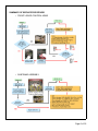
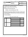
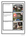
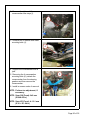
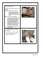
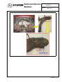
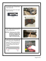
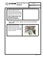
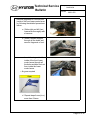
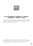
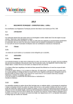
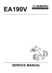
1
Dear 2001-2003 Elantra or 2003 Tiburon Owner:
This notice is sent to you in accordance with the requirements of the National Traffic and Motor
Vehicle Safety Act.
Hyundai has decided that a defect, which relates to motor vehicle safety, exists in certain model
year 2001 through 2003 Hyundai Elantra vehicles that were produced during the period beginning June 30, 2000 through January 13, 2003 and certain model year 2003 Hyundai Tiburon
vehicles produced beginning on October 26, 2001 through January 13, 2003. This recall affects
such vehicles registered in and operated in Connecticut, Delaware, Illinois, Indiana, Iowa,
Maine, Maryland, Massachusetts, Michigan, Minnesota, Missouri, New Hampshire, New Jersey, New York, Ohio, Pennsylvania, Rhode Island, Vermont, West Virginia, and Wisconsin, and
the District of Columbia (the Salt Belt).
Federal law requires that any vehicle lessor receiving this recall notice must forward a copy of
this notice to the lessee within ten days.
What is the problem?
"During winter months, large quantities of salt are used to de-ice roads in the Salt Belt states,
noted above. Road salt may result in internal corrosion and thinning of the steel in the front
lower control arms. In severe cases, the corrosion may progress to the point where the lower
control arm's upper and lower panels become perforated. A perforated front lower control arm
may fracture between its ball joint attachment and the forward and rearward pivot attachments
to the chassis. This could affect your control over the tire and wheel assembly.
Reduced control of the front wheel direction may increase the risk of a vehicle crash without
warning.
What will Hyundai do?
"We are asking you to schedule an appointment as soon as possible to take your vehicle to your
Hyundai dealer. The Hyundai dealer will inspect the front lower control arms for corrosion
damage. If specified levels of internal corrosion damage are found, the front lower control arms
will be replaced with new front lower control arms incorporating additional holes in the upper
and lower panels. If your front lower control arms do not require replacement, the dealer will
add drainage holes to the front lower control arms and will treat the front lower control arms
with rust-proofing material to arrest the internal corrosion process.
In addition to treating the front lower control arms, the Hyundai dealer will inspect the front
subframe of your vehicle for signs of corrosion that could potentially progress and ultimately
affect vehicle performance. This additional inspection is a precautionary measure to offer
improved drainage in the front subframe. If the dealer finds a specified level of corrosion damage, the dealer will replace the front subframe. Otherwise, the dealer will treat the front subframe with rust-proofing materials and add drainage holes.
Page 1 of 35
Both procedures will be performed at no charge to you. You should plan to leave your vehicle
at your Hyundai dealer to have this service performed. Repair times will vary and depend on
your dealer's appointment schedule.
What should you do?
"We urge you to call your Hyundai dealer to schedule an appointment to have this work performed as soon as possible.
What if you have other questions?
"If you have any difficulty having this repair performed, we recommend that you call the Hyundai Customer Assistance Center at 1-800-633-5151. If you are still not satisfied that we have
remedied this situation without charge, and within a reasonable amount of time, you may wish
to write to the Administrator, National Highway Traffic Safety Administration, 1200 New Jersey Avenue, SE, Washington, D.C. 20590, or call their toll-free Vehicle Safety Hotline at 1-888327-4236 (TTY: 1-800-424-9153), or go to http://www.safercar.gov.
Reimbursement Notification
"Hyundai has a program for reimbursing owners of 2001 through 2003 Elantras and 2003 Tiburons produced through January 13, 2003 who paid to have the front lower control arms replaced
after April 14, 2008 and prior to receiving this recall notification letter.
To obtain information about reimbursement from Hyundai, please call the Hyundai Customer
Assistance Center at 1-800-633-5151. Ask about reimbursement information for campaign
091.
We urge your prompt attention to this important safety matter.
Hyundai Motor America
Page 2 of 35
July 10, 2009
TO:ALL HYUNDAI DEALER PRINCIPALS/GENERAL MANAGERS:
ALL HYUNDAI DEALERSHIP SERVICE MANAGERS:
ALL HYUNDAI DEALERSHIP PARTS MANAGERS:
ALL HYUNDAI DEALERSHIP SALES MANAGERS:
SUBJECT: Recall Campaign 091 - Front Lower Control Arm and Front Subframe Corrosion TSB# 09-01-022
Hyundai Motor America is conducting a Customer Notification for inspection and rust-proofing
treatment or replacement of the front lower control arms and front sub-frame on certain 2001 2003 model year Elantra and 2003 Tiburon model year vehicles.
This campaign provides a procedure for the inspection and rust-proofing treatment or replacement of the front lower control arms and front subframe.
In order to identify only those vehicles affected by Campaign 091, it will be necessary to access
Hyundai Motor America's "Warranty Vehicle Information" screen via WEBDCS before starting
the repair. The "Warranty Vehicle Information" screen will identify affected vehicles with an
open Campaign 091.
Dealer Letter, Customer Letter, and Technical Service Bulletin #9-01-022 will be posted on
Hyundai's Website July 10, 2009.
All Hyundai dealers will be shipped a supply of the following materials in their weekly parts
shipments as part of the Subframe/Trailing Arms/Front Lower Control Arms campaigns:
1.Tool kit(s)
2.Chemical kit - additional chemicals can be ordered from your facing PDC as more chemicals
are required.
Customer notification letters will be mailed in weekly flights starting Friday, July 17, 2009.
It is IMPORTANT TO SUBMIT A CAMPAIGN CLAIM FOR EACH VEHICLE SERVICED
so your dealership can be compensated for your work and Hyundai can maintain accurate
records of campaign completions.
LEGAL LIABILITY NOTICE: You are required to keep confidential any and all information
and documents provided to you by Hyundai Motor America in the conduct of carrying out work
for this recall campaign. Hyundai Motor America dealers may use owner information provided
for the recall campaign only for the purpose of conducting and performing this recall campaign,
and for no other purpose.
Page 3 of 35
Hyundai appreciates your cooperation and support. Questions may be directed to your District
Parts and Service Manager or Warranty HELPREP line at 1-877-446-2922.
HYUNDAI MOTOR AMERICA
Page 4 of 35
Technical Service
Bulletin
Group
CAMPAIGN
Number
09-01-022
Date
Subject
XD ELANTRA, GK TIBURON - FRONT LOWER
CONTROL ARM AND FRONT SUBFRAME
CORROSION TREATMENT (CAMPAIGN 091)
CIRCULATE TO:
[X] SERVICE ADVISOR
JULY, 2009
Model
ELANTRA (XD); TIBURON (GK)
[ ] GENERAL MANAGER [X] PARTS MANAGER
[X] SERVICE MANAGER [X] WARRANTY MGR
[X] TECHNICIAN
[ ] SALES MANAGER
IMPORTANT: DEALERS MUST PERFORM THIS CAMPAIGN ON ALL AFFECTED
VEHICLES WHENEVER AN AFFECTED VEHICLE IS IN THE SHOP
FOR ANY MAINTENANCE OR REPAIR.
IMPORTANT: WHEN A VEHICLE ARRIVES AT THE SERVICE DEPARTMENT,
ACCESS HYUNDAI MOTOR AMERICA’S “WARRANTY VEHICLE
INFORMATION” SCREEN VIA WEBDCS TO IDENTIFY OPEN
CAMPAIGNS.
DESCRIPTION:
• Some 2001-2003 Elantra (XD) and 2003 Tiburon (GK) vehicles that are
registered and operated in specified “salt belt” states may exhibit corrosion
damage to the front lower control arms.
• Inspect the front lower control arms for corrosion damage. Measure the
thickness of the front lower control arm steel. If specified levels of corrosion
damage have occurred, as described in this bulletin, replace the front lower
control arms with new front lower control arms that incorporate additional
holes in the upper and lower panels. If the front lower control arms do not
require replacement, add drainage holes and treat the front lower control
arms with rust-proofing material.
• Inspect the front subframes for corrosion damage. As a precautionary
measure and to improve drainage from the subframe, add drainage holes
and treat the front subframe with rust-proofing material. If corrosion
perforation is found as described in this bulletin, replace the front subframe.
Page 5 of 35
SUMMARY OF SERVICE PROCEDURE:
• FRONT LOWER CONTROL ARMS
• SUBFRAME ASSEMBLY
Page 6 of 35
Technical Service
Bulletin
Group
CAMPAIGN
Number
09-01-022
APPLICABLE VEHICLES - VERIFY THAT THE VEHICLE IS IDENTIFIED AS
AFFECTED BY THE CAMPAIGN VIA WEBDCS:
Models: 2001-2003 (XD) Elantra, 2003 (GK) Tiburon
Applicable vehicle production date range:
• XD Elantra - From Job#1 through January 13, 2003.
• GK Tiburon - From Job#1 through January 13, 2003.
Area: Salt belt states: Connecticut, Delaware, Illinois, Indiana, Iowa, Maine, Maryland,
Massachusetts, Michigan, Minnesota, Missouri, New Hampshire, New Jersey, New
York, Ohio, Pennsylvania, Rhode Island, Vermont, West Virginia, Wisconsin and the
District of Columbia.
PARTS (KIT) REQUIRED:
FRONT LOWER CONTROL ARMS
Model
Kit #
Components
Remark
Lower arm, LH
Lower arm, RH
XD
54505-2D002QQH
Nut, 2EA
Bolt, 2EA
Bolt, 4EA
G bush mounting
A bush mounting
Lower arm, LH
Lower arm, RH
GK
54505-2C607QQH
Nut, 2EA
Bolt, 2EA
Bolt, 4EA
G bush mounting
A bush mounting
Page 7 of 35
A: A bush mounting bolt
B: G bush mounting bolt
SUBFRAME ASSEMBLY
Model
Kit #
Components
XD
62405-2D011QQH
Subframe, 2 nuts, 2 bolts
GK
62405-2C511QQH
Subframe, 2 nuts, 2 bolts
Remark
WAX APPLICATION FOR CORROSION PREVENTION
Model
XD/GK
Kit #
62460-2D000QQH
Components
Remark
2 Rubber plugs
For plugging 40mm holes after
wax application.
Page 8 of 35
Technical Service
Bulletin
Group
CAMPAIGN
Number
09-01-022
TOOLS REQUIRED (not supplied in tool kit - Dealer supplied)
No.
Name
Image
Remark
1
Hammer
2
Electric drill
3
Drill bit (8mm
diameter)
Center-pointed type
4
Drill bit (12mm
diameter)
Center-pointed type
Page 9 of 35
5
File
For removing burrs from
around the drilled holes
6
Air gun
Straight nozzle type
NOTE: Additional drill bits should be obtained from your local Parts Supply
vendor when needed.
TOOL KIT (supplied to dealers by HMA)
No.
Name
1
Hole saw (40mm
diameter)
Image
Remark
Provided in tool kit
Usage tips:
1. Remove plug ejection
spring from arbor.
2. Use anti-seize compound on arbor threads
when replacing hole
saw.
3. Spin hole saw cutter
before contacting cutting surface to minimize
tooth damage.
2
Hole saw (20mm
diameter)
With center point
Usage tips:
1. Remove plug ejection
spring from arbor.
2. Use anti-seize compound on arbor threads
when replacing hole
saw.
3. Spin hole saw cutter
before contacting cutting surface to minimize
tooth damage.
Page 10 of 35
Technical Service
Bulletin
Group
CAMPAIGN
Number
09-01-022
3
Air gun
90 degree angle nozzle
type; provided in tool kit
4
Thickness gauge
Measuring thickness of
panel
5
Flexible magnet
Flexible type; provided
in tool kit
6
Control arm drilling template
2 templates provided.
Each can be used on
either left or right control
arm.
NOTE: Dealers will automatically be supplied with a Tool Kit from HMA.
NOTE: Additional hole saws and arbors should be obtained by calling SPX at
800-345-2233. Please note the replacement hole saws from SPX are
compatible with the arbors in the supplied tool kit.
Page 11 of 35
Part Number
Description
J-50236
1 5/8” (40mm) Hole Saw
J-50237
1/2” Hex Shank Arbor
J-50238
13/16” (20mm) Hole Saw
J-50239
3/8” Hex Shank Arbor
CHEMICAL KIT:
No.
Name
Image
Remark
1
Wax injection gun
P/N 00232-19036
2
Cavity wax
P/N 00232-19034
1 vehicle per can
Page 12 of 35
Technical Service
Bulletin
3
Undercoating
spray
Group
CAMPAIGN
Number
09-01-022
P/N 00232-19035
Black color
10 vehicles per can
NOTE: Dealers will be supplied with an initial order of the Chemical Kit.
Additional product should be ordered through your facing PDC.
SERVICE PROCEDURE:
• SUBFRAME INSPECTION
1. Lift up the vehicle.
Page 13 of 35
2. Lightly strike the subframe thorougly
with a hammer.
CAUTION: Be careful, DO NOT strike
the subframe too hard to
prevent deformation
damage.
3. Inspect the subframe for corrosion
perforation.
The photo at the right shows corrosion
perforation.
CAUTION: Make sure to inspect for
corrosion perforation
throughout the subframe
including the sides.
NOTE: If there is any corrosion
perforation, replace the
subframe assembly following
the SUBFRAME
REPLACEMENT
PROCEDURE. If no
perforation exists, go to the
SUBFRAME WAX
APPLICATION FOR
CORROSION PREVENTION
procedure.
• SUBFRAME WAX APPLICATION FOR CORROSION PREVENTION
1. Put a marking point (C) on the left side member as indicated in the photo below.
Page 14 of 35
Technical Service
Bulletin
Group
CAMPAIGN
Number
09-01-022
2. Put a marking point on the right side member at the same position as the left side.
Page 15 of 35
3. Put 2 marking points (D, E) on the left side of # 2 member as indicated in the photo.
D: 10mm from the first inflection point of press bending line (yellow dotted line)
E: 5mm from the second inflection point of press bending line (yellow dotted line)
4. Put 2 marking points on the right side of # 2 member at the same positions as the
left side.
Page 16 of 35
Technical Service
Bulletin
Group
CAMPAIGN
Number
09-01-022
5. Center the 40mm hole saw on the
mark (C) and drill a hole on the left
side member.
6. Repeat this procedure for the right.
CAUTION: Protect yourself by
wearing goggles, a
respirator, gloves, etc.
Page 17 of 35
7. Remove burrs from around both the
upper and lower openings of the
drilled holes with a file and remove
remnants of rust from around the
holes prior to wax application.
8. Center the 20mm hole saw on the
mark (D) and drill a hole on the right
side member.
9. Repeat this procedure for the left.
10. Chuck a drill bit 8mm in diameter to
a drill. Center the drill bit on the
mark (E) and drill a hole on the left
side member.
11. Repeat this procedure for the right.
Page 18 of 35
Technical Service
Bulletin
Group
CAMPAIGN
Number
09-01-022
12. Remove fragments of rust from the
inside of the subframe by following
the detailed procedures below.
a. Strike the subframe
thoroughly with a hammer
to loosen internal rust.
b. Insert a flexible magnet
through the 40mm and
20mm holes and remove
fragments of rust.
Page 19 of 35
c. Insert the air gun into the
inside of the subframe
through holes in the right
and left side members
and blow out rust from
inside the subframe.
d. - Air guns required
e. Repeat steps from a) to c)
2 or more times.
Page 20 of 35
Technical Service
Bulletin
Group
CAMPAIGN
Number
09-01-022
13. Pour about 850cc of cavity wax into
the injection gun reservoir. Spray
cavity wax into the inside of the
subframe through all the holes until
wax drains through the holes.
NOTE: Make sure to use one bottle
(1000cc) of cavity wax per
vehicle for the subframe and
front lower control arm. Use
about 150cc cavity wax for
front lower control arm wax
application.
CAUTION: (1) Protect yourself by
wearing goggles, a
respirator, gloves, etc.
CAUTION: (2) Insure proper
ventilation of your
working area.
CAUTION: (3) Be careful NOT to
contaminate nearby parts
and panels with wax or
undercoating.
14. Spray undercoating on the
subframe, especially around the
holes.
Page 21 of 35
15. Cover both 40mm holes with hole
plugs.
Page 22 of 35
Technical Service
Bulletin
Group
CAMPAIGN
Number
09-01-022
• SUBFRAME REPLACEMENT PROCEDURE
This instruction provides a procedure to replace the ELANTRA (XD) and TIBURON
(GK) subframe more easily and efficiently than the original procedure.
Procedure
Original Procedure
Revised Procedure
To replace the crossmember,
remove it simultaneously with the
steering gearbox.
It is possible to remove the crossmember without detaching the
steering gearbox from the vehicle.
DO NOT remove the steering gearbox for the crossmember replacement.
1. Lift the vehicle off the ground.
2. Remove the right and left front
wheels.
3. Remove the right and left wheel side
covers (A).
Page 23 of 35
4. Remove the under cover.
5. Remove the front pipe (B).
6. Remove the right and left lower
control arm ball joint mounting nuts
(C).
7. Remove the right and left stabilizer
link lower ends (D) from the
stabilizer bar.
8. Remove the power steering pipe line
mounting bolts (E).
Page 24 of 35
Technical Service
Bulletin
Group
CAMPAIGN
Number
09-01-022
9. Remove the RH power steering gear
mounting bolts (F).
10. Remove the LH power steering
gear mounting bolts (G).
11. Remove the bolts (H) holding the
front and rear roll stoppers to the
brackets.
Page 25 of 35
12. Remove the right and left
crossmember rear stays (I).
13. Unfasten the 2 washer tank lower
mounting bolts (J).
14. Support the crossmember with a
jack.
15. Removing the 4 crossmember
mounting bolts (K), detach the
crossmember from the steering
gearbox and then remove the
crossmember.
16. Install in reverse order of removal.
NOTE: Perform toe adjustment, if
necessary.
NOTE: Spec GK (Front): 0±2 mm
(0.08±0.08 in.)
NOTE: Spec XD (Front): 4 +3/-1 mm
(0.16 +.12/-.04 in)
Page 26 of 35
Technical Service
Bulletin
Group
CAMPAIGN
Number
09-01-022
• FRONT LOWER CONTROL ARM INSPECTION AND REMOVAL
1. Lift up the vehicle.
2. Lightly strike the right and left front
lower control arms thoroughly with a
hammer.
CAUTION: Be careful, DO NOT strike
the front lower control
arms too hard to prevent
deformation damage.
Page 27 of 35
3. Inspect the lower control arms for
corrosion perforation.
# The photo at the right shows corrosion
perforation.
CAUTION: Inspect for corrosion
perforation throughout the
right and left front lower
control arms including the
sides.
NOTE: If there is any corrosion
perforation on either the right
or left front lower control
arms, replace both right and
left front lower control arm
assemblies following the
applicable shop manual. If no
perforation exists, go to the
next step to further inspect
the front lower control arms
for corrosion.
4. Put a marking point (F) on the left
front lower control arm as indicated
in the photo.
5. Put a marking point on the right front
lower control arm at the same
position as the left side.
Page 28 of 35
Technical Service
Bulletin
Group
CAMPAIGN
Number
09-01-022
Page 29 of 35
6. Center the 12mm drill bit on the mark
(F) and drill a hole on the left front
lower control arm.
7. Repeat this procedure for the right
lower control arm.
8. With a file, remove burrs around the
holes. Totally remove remnants of
rust around the holes.
CAUTION: If the burrs are not fully
removed, it may prevent
the thickness gauge from
being inserted over the
edge of the drilled holes.
9. Inspect the thickness of the front
lower control arm lower panels with
the 1.5mm groove of the thickness
gauge (G). Check the thickness of
the front lower control arms at as
many points around the hole as
possible.
Page 30 of 35
Technical Service
Bulletin
Group
CAMPAIGN
Number
09-01-022
10. If either the right or left front lower
control arm metal fits into the
thickness gauge or is inserted into
the groove, replace both right and left
assemblies. If the front lower control
arm metal does not fit into the 1.5mm
thickness gauge, go to the procedure
FRONT LOWER CONTROL ARM
WAX APPLICATION FOR
CORROSION PREVENTION.
• FRONT LOWER CONTROL ARM WAX APPLICATION FOR CORROSION
PREVENTION
1. Align the right angled triangle
template with the 2 current holes (H)
in the center of the front lower
control arm as shown in the photo at
the right. Put a mark (I) on the right
front lower control arm. Repeat this
procedure for the left.
Page 31 of 35
2. Center the 20mm hole saw on the
mark and drill a hole in the right
lower control arm. Repeat this
procedure for the left.
Page 32 of 35
Technical Service
Bulletin
Group
CAMPAIGN
Number
09-01-022
3. Remove fragments of rust from the
inside of the front lower control arms
by following the detailed procedures
below.
a. Strike right and left front
lower arms thoroughly with
a hammer.
b. Insert a flexible magnet
through all the holes and
remove fragments of rust.
c. Insert the air gun into the
inside of the front lower
control arms through all
the holes and blow out rust
from inside the lower
control arms.
• Air guns required
d. Repeat steps from a) to c)
more than 2 times.
Page 33 of 35
4. Pour about 150cc of cavity wax into
the injection gun reservoir.
5. Spray cavity wax into the inside of
the right and left front lower control
arms through all the holes until wax
drains through the holes.
CAUTION: (1) Protect yourself by
wearing goggles, a
respirator, gloves, etc.
CAUTION: (2) Insure proper
ventilation of your
working area.
CAUTION: (3) Be careful NOT to
contaminate nearby parts
and panels with wax or
undercoating.
6. Spray undercoating around the
holes.
WARRANTY CLAIM INFORMATION:
XD Elantra: Produced from Job #1 through Jan. 13, 2003 (Subframe + Front Lower
Control Arm)
Op Time
Op Code
Description
91B021R0
Subframe / Lower Arm Replacement
2.5
91B021R1*
Subframe Replacement / Lower Arm Inspection & Wax Application
2.8
91B021R2
Subframe Replacement / Lower Arm Inspection & Replacement
2.6
91B021R3*
Subframe Wax Application/ Lower Arm Replacement
1.4
91B021R4*
Subframe Wax Application / Lower Arm Inspection & Wax Application
0.9
91B021R5*
Subframe Wax Application / Lower Arm Inspection & Replacement
1.5
XD
Page 34 of 35
Technical Service
Bulletin
Group
CAMPAIGN
Number
09-01-022
GK Tiburon: Produced from Job #1 through Jan. 13, 2003 (Subframe + Front Lower
Control Arm)
Op Time
Op Code
Description
91B021R6
Subframe / Lower Arm Replacement
2.7
91B021R7*
Subframe Replacement / Lower Arm Inspection & Wax Application
3.1
91B021R8
Subframe Replacement / Lower Arm Inspection & Replacement
2.8
91B021R9*
Subframe Wax Application / Lower Arm Replacement
1.4
91B021RA*
Subframe Wax Application / Lower Arm Inspection & Wax Application
0.9
91B021RB*
Subframe Wax Application / Lower Arm Inspection & Replacement
1.5
GK
NOTE: Submit claims using Campaign Entry Screen
NOTE: * Each applicable claim includes a sublet amount for chemical, hole saw,
and drill bit reimbursement.
NOTE: * Reimbursement for the Wax Injection Gun will be processed in
Dealership’s Parts statement.
PARTS SCRAP INFORMATION:
1. Lower Arm/Subframe Inspection and Replacement (without drilling holes) - It
is required that digital photos be taken of the replaced parts as well as the VIN
plate. These pictures must be attached to their respective repair order for DPSM
review. The removed lower arms/subframe may be scrapped.
2. Lower Arm/Subframe Inspection and Replacement (with drilling holes) - It is
required to retain the core sample and repair information for DPSM review. The
removed lower arms/subframe may be scrapped.
3. Lower Arm/Subframe Inspection and Wax Application - It is required to retain
the core sample and repair information for DPSM review.
Page 35 of 35