1
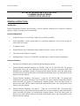
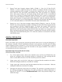
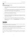
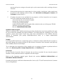
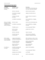
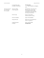
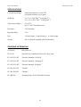
Instruction Manual
Fluoride Electrode
EUTECH INSTRUMENTS PTE LTD.
INSTRUCTION MANUAL
FLUORIDE ION ELECTRODE
1
Instruction Manual
Fluoride Electrode
TABLE OF CONTENTS
GENERAL INSTRUCTIONS .......................................................................................................... 3
Introduction................................................................................................................................................................... 3
Required Equipment ..................................................................................................................................................... 3
Required Solutions........................................................................................................................................................ 3
GENERAL PREPARATION............................................................................................................ 4
Electrode Preparation.................................................................................................................................................... 4
Electrode Slope Check (with pH/mV meter) ................................................................................................................ 4
Electrode Slope Check (with ion meter) ....................................................................................................................... 5
MEASUREMENT.............................................................................................................................. 5
Measuring Hints............................................................................................................................................................ 5
Sample Requirements ................................................................................................................................................... 6
Units of Measurement................................................................................................................................................... 6
MEASUREMENT PROCEDURE ................................................................................................... 6
Direct Measurement...................................................................................................................................................... 6
Direct Measurement of Fluoride (using a pH/mV meter) ............................................................................................. 6
Direct Measurement of Fluoride (using an ion meter).................................................................................................. 8
Direct Measurement of Fluoride in Water (ASTM D1179, METHOD B) ................................................................... 8
Direct Measurement of Fluoride in Acid Solutions ...................................................................................................... 9
Direct Measurement of Fluoride in Alkaline Solutions ................................................................................................ 9
Low Level Fluoride Measurements (using a pH/mV meter) ...................................................................................... 10
Low Level Fluoride Determination (using an ion meter) ........................................................................................... 11
Titration ...................................................................................................................................................................... 12
Titration Procedure for Fluoride Determination ......................................................................................................... 12
ELECTRODE CHARACTERISTICS........................................................................................... 13
Reproducibility ........................................................................................................................................................... 13
Interference ................................................................................................................................................................. 13
Complexation.............................................................................................................................................................. 14
Temperature Influences .............................................................................................................................................. 14
Electrode Response..................................................................................................................................................... 14
Limits of Detection ..................................................................................................................................................... 15
pH Effects ................................................................................................................................................................... 15
Electrode Life.............................................................................................................................................................. 16
Electrode Storage ........................................................................................................................................................ 17
ELECTRODE THEORY ................................................................................................................ 17
Electrode Operation .................................................................................................................................................... 17
TROUBLESHOOTING GUIDE .................................................................................................... 18
Meter........................................................................................................................................................................... 18
Plastic-ware................................................................................................................................................................. 18
Electrodes.................................................................................................................................................................... 18
Standards and Reagents .............................................................................................................................................. 19
Sample ........................................................................................................................................................................ 19
Technique.................................................................................................................................................................... 19
TROUBLESHOOTING HINTS..................................................................................................... 20
SPECIFICATIONS.......................................................................................................................... 22
ORDERING INFORMATION....................................................................................................... 22
2
Instruction Manual
Fluoride Electrode
EUTECH INSTRUMENTS PTE LTD.
FLUORIDE ION ELECTRODE
INSTRUCTION MANUAL
GENERAL INSTRUCTIONS
Introduction
Eutech Instruments Fluoride Ion Electrode is used to measure fluoride ions in aqueous solutions
quickly, simply, accurately, and economically.
Required Equipment
1.
A pH/mV meter or an ion meter, either line operated or portable.
2.
Semi-logarithmic 4-cycle graph paper for preparing calibration curves when using the
meter in the mV mode.
3.
A magnetic stirrer.
4.
Eutech Fluoride Ion Combination Epoxy-body Electrode, Code no. EC-FO-03.
5.
Lab-ware made of plastic, not glass.
6.
Polishing Paper, Code no. EC-MIS-PP, to polish dirty or etched electrode membranes.
Required Solutions
1.
Deionized or distilled water for solution and standard preparation.
2.
Eutech Fluoride Standard Solution, 0.1 M NaF, Code No. EC-SCS-FL1-BT. To prepare
this solution from your own laboratory stock, half fill a one liter volumetric flask with
distilled water and add 4.2 grams of reagent-grade sodium fluoride. Swirl the flask gently
to dissolve the solid. Fill the flask to the mark with distilled water, cap, and upend several
times to mix the solution.
3.
Eutech Fluoride Standard, 1,000 ppm F-1, Code No. EC-SCS-FL2-BT. To prepare this
solution from your own laboratory stock, half fill a one liter volumetric flask with distilled
water and add 2.21 grams of reagent-grade sodium fluoride. Swirl the flask gently to
dissolve the solid. Fill the flask to the mark with distilled water, cap, and upend several
times to mix the solution.
4.
Eutech Fluoride Standard, 100 ppm F-1, Code No. EC-SCS-FL3-BT. To prepare this
solution from you own laboratory stock, half fill a one liter volumetric flask with distilled
water and add 0.22 grams of reagent-grade sodium fluoride. Swirl the flask gently to
dissolve the solid. Fill the flask to the mark with distilled water, cap, and upend several
times to mix the solution.
3
Instruction Manual
Fluoride Electrode
5.
Eutech Total Ionic Strength Adjuster Buffer (TISAB 1), Code No. EC-ISA-FL1-BT.
TISAB 1 is used to adjust the pH of the solution, de-complex fluoride and provide a
constant background ionic strength. To prepare this solution from your own laboratory
stock, half fill a four liter beaker with distilled water. Place the beaker on a magnetic
stirrer, add a large stirring bar, and begin stirring. Slowly add 230 ml of concentrated
acetic acid, 232 grams of reagent-grade sodium chloride, and 16 grams of reagent-grade
CDTA. After the solids have dissolved, allow the solution to cool to room temperature.
Slowly add 150 grams of reagent-grade sodium hydroxide. After the solids have dissolved,
allow the solution to cool to room temperature. Calibrate a pH electrode and adjust the pH
to 5.25 with small addition of 5 M NaOH. Fill to the mark with distilled water.
6.
Eutech Low Level Total Ionic Strength Adjuster Buffer (TISAB 2), Code No. EC-ISAFL2-BT. Use when measuring in samples containing less than 2X10⁻⁵M (0.4 ppm) fluoride
and containing no fluoride complexing agents. To prepare this solution from your own
laboratory stock, place about 2'000 ml distilled water in a four liter beaker. Add 57 ml
glacial acetic acid and 58 grams sodium chloride. Place the beaker on a magnetic stirrer,
add a stirring bar and begin stirring. Immerse a calibrated pH electrode into the solution.
Slowly add 5 M NaOH until the pH is 5.25. Allow the solution to cool and fill to the mark
with distilled water.
GENERAL PREPARATION
Electrode Preparation
Remove the rubber caps covering the electrode tips and the rubber insert covering the filling hole of
the reference electrode. Fill the combination electrode or the reference electrode with the filling
solution shipped with the electrode to a level just below the fill hole. No preparation is required
with a sealed reference electrode. Connect the electrodes to the proper terminals of the meter as
recommended by the meter manufacturer.
Electrode Slope Check (with pH/mV meter)
(Check electrodes each day)
1.
To a 150 ml plastic beaker, add 50 ml of distilled water and 50 ml of TISAB. Place the
beaker on a magnetic stirrer and begin stirring at a constant rate. After assuring that the
meter is in the millivolt mode, lower the electrode tips into the solution.
2.
Using a pipet, add 1 ml of 0.1M, 1,000 ppm, or 100 ppm fluoride standard to the beaker.
When the reading has stabilized, record the mV reading.
3.
Using a pipet, add 10 ml of the same fluoride standard used above to the beaker. When the
reading has stabilized, record the mV reading.
4.
Determine the difference between the two readings. The electrode is operating correctly if
the millivolt potential has changed by 57±2 mV, assuming the solution temperature is
between 20o and 25oC. See the TROUBLESHOOTING section if the potential change is not
within this range.
4
Instruction Manual
Fluoride Electrode
Slope is defined as the change in potential observed when the concentration changes by a factor of
10.
Electrode Slope Check (with ion meter)
(Check electrodes each day)
1.
Prepare standard fluoride solutions whose concentrations vary by tenfold. Use either the
0.1M, 1,000 ppm, or 100 ppm fluoride standard. Use the serial dilution method for this
preparation.
2.
To a 150 ml beaker, add 50 ml of the lower value standard and 50 ml of TISAB. Place the
beaker on the magnetic stirrer and begin stirring at a constant rate. Lower the electrode tips
into the solution. Assure that the meter is in the concentration mode.
3.
Adjust the meter to the concentration of the standard and fix the value in the memory
according to the meter manufacturer's instructions.
4.
Rinse the electrodes with distilled water and blot dry.
5.
To another 150 ml beaker, add 50 ml of the higher value standard and 50 ml of TISAB.
Place the beaker on the magnetic stirrer and begin stirring at a constant rate. Lower the
electrode tips into the solution.
6.
Adjust the meter to the concentration of the standard and fix the value in the memory.
7.
Read the electrode slope according to the meter instructions. Correct electrode operation is
indicated by a slope of 90-100%. See the TROUBLESHOOTING section if the slope is not
within this range.
MEASUREMENT
Measuring Hints
All samples and standards should be at the same temperature for precise measurement. A difference
of 1oC in temperature will result in a 2% measurement error.
Constant, but not violent, stirring is necessary for accurate measurement. Magnetic stirrers can
generate sufficient heat to change the solution temperature. To counteract this effect, place a piece
of insulating material, such as a styrofoam sheet, between the stirrer and the beaker.
Always rinse the electrodes with distilled water and blot dry between measurements. Use a clean,
dry tissue to prevent cross-contamination.
For samples with high ionic strength, prepare standards whose composition is similar to the sample.
Always check to see that the membrane is free from air bubbles after immersion into standard or
sample.
5
Instruction Manual
Fluoride Electrode
Sample Requirements
All samples must be aqueous and not contain organics which can dissolve the epoxy electrode body
and/or the cement bonding the sensing crystal to the electrode body. Inorganic solutions will not
affect the electrode. Infrequent measurements in solutions containing methanol, acetone, or dioxane
are permitted. Highly polar solvents, such as CHCl3 or DMF, should not be contained in the
samples. Please check with Eutech Instruments Pte Ltd. before using the electrode in other organic
solvents.
The addition of TISAB to samples and standards will adjust the pH to 5.0-5.5. Samples must be
above pH 5 to avoid forming complexes with hydrogen ions and below pH 7 to avoid interference
by hydroxide ions.
The temperature of the standard solutions and of the sample solutions should be the same and below
80oC. The use of TISAB 1 also preferentially forms complexes with aluminum and with iron,
breaking the complexes that fluoride forms with these ions. With 1 ppm fluoride present, up to 3-5
ppm aluminum or iron is complexed. If higher levels of aluminum or iron are present, use TISAB 3.
Units of Measurement
Fluoride concentrations are measured in units of ppm as fluoride, moles per liter, or any other
convenient concentration unit. Table 1 indicates some concentration units and conversion factors.
TABLE 1: Concentration Unit Conversion Factors
ppm F-1
190.0
19.0
1.9
moles/liter
1.0X10⁻²M
1.0X10⁻³M
1.0X10⁻⁴M
MEASUREMENT PROCEDURE
Direct Measurement
Direct measurement is a simple procedure for measuring a large number of samples. A single meter
reading is all that is required for each sample. The ionic strength of samples and standards should
be made the same by adjustment with TISAB for all fluoride solutions. The temperature of both
sample solution and standard solution should be made the same.
Direct Measurement of Fluoride (using a pH/mV meter)
1.
By serial dilution, prepare three standard solutions from the 0.1M, 1,000 ppm, or the 100
ppm stock standard. The resultant concentrations should be 10-2M, 10-3M, and 10-4M or
100, 10, and 1 ppm. Add 50 ml of TISAB 1 or TISAB 2 to each 50 ml of standard. When
calibrating, assume that the added TISAB has no effect on the standard concentration.
2.
Place the most dilute solution on the magnetic stirrer and begin stirring at a constant rate.
After assuring that the meter is in the mV mode, lower the electrode tips into the solution.
After the reading has stabilized, record the mV reading.
6
Instruction Manual
Fluoride Electrode
3.
Place the mid-range solution on the magnetic stirrer and begin stirring. After rinsing the
electrodes with distilled water, blot dry, and immerse the electrodes in the solution. When
the reading has stabilized, record the mV value.
4.
Place the most concentrated solution on the magnetic stirrer and begin stirring. After
rinsing the electrodes with distilled water, blot dry, and immerse the electrodes in the
solution. When the mV reading has stabilized, record the mV value.
5.
Using the semi-logarithmic graph paper, plot the mV reading (linear axis) against the
concentration (log axis). Extrapolate the curve down to about 1.0X10⁻⁵M. A typical
calibration curve can be found in Figure 1.
A calibration curve is constructed on semi-logarithmic paper when using the pH/mV
meter in the millivolt mode. The measured electrode potential in mV (linear axis) is
plotted against the standard concentration (log axis). In the linear region of the
curve, only three standards are necessary to determine a calibration curve. In the
non-linear region, additional points must be measured. The direct measurement
procedures given are for the linear portion of the curve. The non-linear portion of the
curve requires the use of low level procedures.
6.
To a clean, dry, 150 ml plastic beaker, add 50 ml of sample and 50 ml of TISAB 1 or
TISAB 2. Place the beaker on the magnetic stirrer and begin stirring. Rinse the electrodes
with distilled water, blot dry, and lower the electrode tips into the solution. When the
reading has stabilized, record the mV reading. Using the calibration curve, determine the
sample concentration.
7.
The calibration should be checked every 1-2 hours. Assuming no change in ambient
temperature, place the electrode tips in the mid-range standard. After the reading has
stabilized, compare it to the original reading recorded in Step 3 above. A reading differing
by more than 0.5 mV or a change in the ambient temperature will necessitate the repetition
of Steps 2-5 above. A new calibration curve should be prepared daily.
7
Instruction Manual
Fluoride Electrode
Direct Measurement of Fluoride (using an ion meter)
1.
By serial dilution of the 0.1M, 1,000 ppm, or 100 ppm fluoride standard, prepare two
fluoride standards whose concentration is near the expected sample concentration. Add 50
ml of TISAB 1 or TISAB 2, to each 50 ml of standard. When calibrating, assume that the
added TISAB has no effect on the standard concentration.
2.
Place the more dilute solution on the magnetic stirrer and begin stirring at a constant rate.
Assure that the meter is in the concentration mode.
3.
Lower the electrode tips into the solution.
4.
Adjust the meter to the concentration of the fluoride standard and fix the value in the
memory according to the meter manufacturer's instructions after stabilization of the
reading.
5.
Rinse the electrodes with distilled water and blot dry.
6.
Place the more concentrated solution on the magnetic stirrer and begin stirring at a
constant rate.
7.
Lower the electrode tips into the solution.
8.
Adjust the meter to the concentration of the fluoride standard and fix the value in the
memory according to the manufacturer's instructions after stabilization of the reading.
9.
For low level measurements, place the rinsed, dried electrodes into a solution containing
equal volumes of distilled water and TISAB 1 or TISAB 2 (or add 10 ml of TISAB 2 to
each 100 ml of distilled water). After stabilization, fix the blank value in the meter
according to the meter manufacturer's instructions.
10.
After rinsing the electrodes and blotting dry, place the electrode tips into the sample
diluted with an equal volume of TISAB 1 or TISAB 2. After stabilization, read the
concentration directly from the meter display.
11.
The calibration should be checked every 1-2 hours. Assuming no change in ambient
temperature, place the electrode tips in the first fluoride standard. After the reading has
stabilized, compare it to the original reading in Step 4 above. A reading differing by more
than 0.5 mV or a change in ambient temperature will necessitate repetition of Steps 2-8 (29) above. The meter should be re-calibrated daily.
Direct Measurement of Fluoride in Water (ASTM D1179, METHOD B)
The procedure is used to determine total fluoride concentration in water in ppm. TISAB is added to
standards and to samples in order to break fluoride complexes of iron and aluminum, adjust the pH,
and provide a constant ionic strength. Fluoride sample concentration is determined, using this
method, independent of the level or nature of dissolved minerals.
8
Instruction Manual
Fluoride Electrode
Prepare 2, 1, and 0.5 ppm fluoride standards by serial dilution of the 100 ppm fluoride standard. To
each 50 ml of standard, add 50 ml of TISAB 1 or TISAB 2. Calibrate the meter as previously
described by using the 2, 1, and 0.5 ppm standards. The calibration curve should be drawn on semilogarithmic 2-cycle graph paper or use an ion meter.
Direct Measurement of Fluoride in Acid Solutions
Hydrogen ion complexes a portion of the fluoride ion in solutions with a pH below 5, forming HF
or HF2-1, which cannot be detected by the electrodes. Adjustment to weakly acidic/weakly basic
range before making the fluoride determination is necessary, but not with strongly basic solutions.
The use of sodium acetate buffers the pH above 5 and helps fix the total ionic strength of standards
and samples to the same level.
1.
Dissolve reagent grade sodium acetate (CH3COONa) in distilled water to prepare a 15%
solution. Prepare a sufficient quantity to dilute all standards and samples.
2.
Prepare a blank solution containing all components of the sample except fluoride. This
solution will be used to prepare standards.
3.
Add fluoride to the blank solution to prepare standards in the concentration range of the
unknown solutions. If using a standard pH/mV meter, prepare three standards and a
calibration curve as previously described. If an ion meter is used, only two standards are
necessary. Add 9 parts of sodium acetate to each 1 part of standard. Fresh standards should
be prepared every two weeks if the standard contains less than 10 ppm fluoride.
4.
Calibrate the electrodes as described in the section Electrode Slope Check.
5.
After diluting each unknown sample 10:1 with sodium acetate (as in 3 above), measure the
mV potential and determine the fluoride concentration.
Direct Measurement of Fluoride in Alkaline Solutions
Hydroxide ions interfere with fluoride measurements in basic solutions with a low fluoride content.
At a fluoride concentration less than 1.0X10⁻⁴M and at a pH of 9.5 or above, the electrode potential
reading, caused by the concentration of both hydroxide and fluoride ions, is higher than it would be
if fluoride alone were present. (See section entitled pH Effects.)
Using a 4M buffered potassium acetate solution to adjust the pH to between 5 and 6 eliminates
hydroxide ion error and raises the total ionic strength of both standards and samples to the same
value. The fluoride ion concentration can be determined in the usual manner after both standards
and samples are diluted 10:1 with the buffer solution.
1.
To prepare a 4M buffered potassium acetate solution, add one part of distilled water,
slowly, to two parts of 6M acetic acid, CH3COOH, in a large beaker surrounded by a water
bath. Slowly add 50% KOH solution to the acetic acid mixture, with constant stirring,
until a pH of 5 is reached. Prepare enough buffer to dilute all standards and samples 10:1.
9
Instruction Manual
2.
Fluoride Electrode
Following the directions given in the preceding section (Determination of Fluoride in
Acid Solutions), prepare standards, calibrate the electrodes and measure the unknown
samples.
Low Level Fluoride Measurements (using a pH/mV meter)
Use the following low level fluoride measurement procedure in the non-linear portion of the
calibration curve. (See Figure 1.) This procedure is used for fluoride samples containing less than
2X10⁻⁵M or 0.4 ppm fluoride and containing no fluoride complexing agents. Use low level TISAB
2 for both samples and standards. A longer response time should be expected for low level fluoride
measurements.
1.
By serial dilution, prepare a 1.0X10⁻³M or 10 ppm fluoride standard by diluting the 0.1M,
1,000 ppm, or 100 ppm standard solution. Add 50 ml low level TISAB 2 to 50 ml of
standard solution.
2.
Using a 150 ml beaker, add 50 ml of distilled water and 50 ml of low level TISAB 2.
Place the beaker on the magnetic stirrer and begin stirring at a constant rate. Lower the
electrode tips into the solution. Assure that the meter is in the mV mode.
3.
Increments of the standard should be added to the beaker according to the steps outlined in
Table 2 below. After the reading stabilizes, record the mV reading for each addition.
TABLE 2: Low Level Measurement Calibration Curve
Step
1
2
3
4
5
6
7
Pipet
A
A
A
A
A
B
B
Added
Volume (ml)
0.1
0.1
0.2
0.2
0.4
2.0
2.0
Concentration
ppm
M
0.01
1.0X10⁻⁶
0.02
2.0X10⁻⁶
0.04
4.0X10⁻⁶
0.06
6.0X10⁻⁶
0.10
1.0X10⁻⁵
0.29
2.9X10⁻⁵
0.48
4.8X10⁻⁵
Pipet A = 1 ml graduated pipet
Pipet B = 2 ml pipet
Solutions: additions of standard / TISAB 2 to 50 ml of distilled water
and 50 ml of low level TISAB 2.
4.
On semi-logarithmic graph paper, plot the concentration (log axis) against the millivolt
reading (linear axis) as in Figure 1. Keep the final solution for checking the electrode
calibration.
5.
To a 150 ml plastic beaker, add 50 ml of sample and 50 ml of low level TISAB 2. Place the
beaker on a magnetic stirrer and begin stirring. After rinsing the electrodes and blotting
dry, place the electrode tips into the solution. After stabilization of the reading, read the
mV potential and determine the concentration from the calibration curve. A new low level
calibration curve should be prepared daily using fresh standards.
10
Instruction Manual
Fluoride Electrode
Low Level Fluoride Determination (using an ion meter)
Follow the previous procedure for fluoride measurements with an ion meter, except use low level
TISAB 2 instead of TISAB 1. Always use the blank correction.
11
Instruction Manual
Fluoride Electrode
Titration
Titration is a very accurate determination of fluoride. Eutech Fluoride Ion Electrodes can be used as
highly sensitive endpoint detectors for titration of a fluoride-containing sample. Though titration are
more time consuming than direct ion measurements, the results are more accurate and reproducible.
Titration accurate to ±0.2% of the total fluoride concentration of the sample can be performed using
lanthanum nitrate as the titrant. Total fluoride concentration should be at least 1.0X10⁻³M for
endpoint detection. Low results are given if aluminum, iron, or trivalent chromium are present at a
level of 1% or higher.
Special titration procedures for aluminum, lithium, lanthanum, and thorium also makes use of the
fluoride electrode as an endpoint indicator.
Titration Procedure for Fluoride Determination
1.
Dissolve 43.3 grams of reagent grade lanthanum nitrate, La(NO3)3.6H2O, in about 500 ml
distilled water in a 1 liter volumetric plastic flask. Fill to the mark with distilled water.
This 0.1M lanthanum solution will be used for all titration.
2.
Using the 0.1M fluoride standard, standardize the lanthanum nitrate by titration. To a 150
ml plastic beaker, add approximately 9.0 ml of fluoride standard (accurately measured) and
about 50 ml of distilled water. Place the beaker on the magnetic stirrer and begin stirring.
Lower the electrode tips into the solution.
3.
Using a 10 ml plastic burette, add the La(NO3)3 titrant in 0.5-1.0 ml increments. Record the
mV reading against the volume of titrant added. As the mV potential change increases, add
smaller increments, down to 0.1-0.2 ml increments. Continue to add titrant and record the
mV potential against the volume until little change is noted in the mV reading even when
adding 0.5-1.0 ml increments.
4.
Using linear graph paper, plot the mV readings (y-axis) against the volume (x-axis). The
end-point is determined as the steepest slope on the titration curve. Record the endpoint.
o
Vt
5.
To a 150 ml plastic beaker, add approximately 9.0 ml of sample solution (accurately
measured) and about 50 ml of distilled water. Place the beaker on a magnetic stirrer and
begin stirring. Lower the rinsed, dried electrode tips in the solution.
6.
7.
Titrate the sample as in step 3 above. The endpoint is denoted as x
x
Vt
Calculate the sample concentration, Cs
x o
Vt Vf o
x
Cs = ⎯⎯⎯⎯⎯ . 2Cs
o x
Vt Vf
where:
x
12
Instruction Manual
Cs
o
Cs
x
Vt
Vt
x
Vf
Vf
Fluoride Electrode
= concentration of sample
= fluoride standard concentration (0.1M)
= volume of titrant added to achieve the endpoint of unknown sample
= volume of titrant added to achieve the endpoint in standardization
= volume of sample used in sample titration
= volume of standard used in standardization titration.
A typical titration curve is shown in Figure 2.
ELECTRODE CHARACTERISTICS
Reproducibility
Electrode measurements reproducible to ±2% can be obtained if the electrode is calibrated every
hour. Factors such as temperature fluctuations, drift, noise, and variations in illumination limit
reproducibility. Reproducibility is independent of concentration within the electrode's operating
range.
Interference
The hydroxide ion, OH-1, is an electrode interference. Anions which make the sample more basic,
such as CO3-2 or PO4-3 would increase the OH-1 interference, but do not interfere with direct
electrode operation. Other anions commonly associated with fluoride, such as Cl-1, Br-1, I-1, SO4-2,
HCO3-1, NO3-1, and acetate, do not interfere with correct electrode operation. Most cations do not
interfere with the response of the fluoride electrode to fluoride ion.
13
Instruction Manual
Fluoride Electrode
Complexation
Hydrogen ion, as well as some other multivalent cations, aluminum, silicon, iron+3, will form
complexes with fluoride. The total ionic strength of the solution, the pH of the solution, the total
fluoride concentration, and the concentration of the complexing agent all contribute to the degree of
complexation. TISAB 1 and TISAB 2 complex about 5 ppm aluminum or iron in a 1 ppm fluoride
solution.
Temperature Influences
Samples and standards should be within ±1oC of each other, since electrode potentials are
influenced by changes in temperature. Because of solubility equilibrium on which the electrode
depends, the absolute potential of the reference electrode changes slowly with temperature. The
slope of the electrode, as indicated by the factor "S" in the Nernst equation, also varies with
temperature. Table 3 gives values for the "S" factor in the Nernstian equation for the fluoride ion.
TABLE 3: Temperature vs. Values for the Electrode Slope
Temp (oC)
0
10
20
25
30
40
50
"S"
54.20
56.18
58.18
59.16
60.15
62.13
64.11
The temperature range for the Eutech Fluoride Ion Electrodes is 0o-80oC, provided that temperature
equilibrium has occurred. Only intermittent use is recommended at temperatures from 80o-100oC.
If the temperature varies substantially from room temperature, equilibrium times up to one hour are
recommended.
Electrode Response
Plotting the electrode mV potential against the fluoride concentration on semi-logarithmic paper
results in a straight line with a slope of about 57 mV per decade. (Refer to Figure 1.)
The time needed to reach 99% of the stable electrode potential reading, the electrode response time,
varies from one minute or less in highly concentrated solutions to several minutes near the detection
limit. (Refer to Figure 3.)
14
Instruction Manual
Fluoride Electrode
A drifting potential reading or a decrease in electrode slope may mean that the electrode membrane
needs polishing.
To polish the membrane:
1.
If using polishing paper, cut off a 1-2" piece and place it face up on the lab bench.
2.
Put a few drops of distilled or deionized water in the center of the paper.
3.
Holding the paper (cotton) steady with one hand, bring the membrane of the electrode
down perpendicular to the paper and, with a slight swirling motion, gently polish the tip of
the electrode against the surface of the polishing paper (cotton) for a few seconds.
4.
Rinse the electrode surface with distilled or deionized water and soak the electrode tip in
standard solution for about five minutes before use.
5.
If using jeweller's rouge, place a cotton ball on the table top and flatten it using the bottom
of a beaker.
6.
Put 1-2 drops of distilled or deionized water in the center of the cotton pad.
7.
Add a small amount of jeweller's rouge to the damp cotton.
8.
Continue with Steps 3 and 4 above.
Limits of Detection
Fluoride concentration down to 1.0X10⁻⁶M (0.02 ppm) fluoride can be measured in neutral
solutions. Since sample contamination can be a factor in low level fluoride measurements, care
must be taken in making determinations below 1.0X10⁻⁵M. The upper limit of detection is a
saturated fluoride solution.
pH Effects
Hydrogen complexes a portion of fluoride in solution, forming the un-dissociated acid HF and the
ion HF2-1 in acid solutions with a pH below 5. The proportion of free fluoride ion in acid solutions
is shown in Figure 4.
15
Instruction Manual
Fluoride Electrode
When the level of hydroxide is greater than one-tenth the level of fluoride ion present, hydroxide
ion interferes with electrode response to fluoride. As an example, no hydroxide interference with
fluoride measurements take place at pH 7 when the hydroxide concentration is 1.0X10⁻⁷ or less. As
the pH increases, the hydroxide interference becomes appreciable. At pH 10, hydroxide ion
concentration is 1.0X10⁻⁴M and no error is found in measurements of 1.0X10⁻²M fluoride. At the
same hydroxide ion concentration and a fluoride concentration of 1.0X10⁻⁴M, about a 10%
measurement error appears. At a fluoride concentration of 1.0X10⁻⁵M, considerable error exists in a
pH 10 solution. Figure 5 illustrates these errors.
The addition of TISAB 1 or TISAB 2 to all fluoride samples and standards buffers the pH between
5.0-5.5 to help avoid hydroxide interference or the formation of hydrogen complexes of fluoride.
Electrode Life
A fluoride electrode will last six months in normal laboratory use. On-line measurements might
shorten operational lifetime to several months. In time, the response time will increase and the
calibration slope decreases to the point calibration is difficult and electrode replacement is required.
16
Instruction Manual
Fluoride Electrode
Electrode Storage
The fluoride electrode may be stored for short periods of time in 1.0X10⁻²M fluoride solution with
TISAB added. For longer storage (longer than two weeks), rinse and dry the sensing pellet and
cover the membrane tip with any protective cap shipped with the electrode. The reference portion of
the combination electrode (or the outer chamber of the reference electrode) should be drained of
filling solution, if refillable, and the rubber insert placed over the filling hole. The fluoride electrode
should never be stored in distilled water.
ELECTRODE THEORY
Electrode Operation
The fluoride electrode consists of a single crystal of lanthanum fluoride as the membrane, bonded
into a glass or an epoxy body. Only fluoride ions are mobile in the ionic conductor crystal. When
the membrane comes in contact with a solution containing fluoride ions, a potential develops across
the membrane. This potential is measured against an external (or internal) constant reference
potential with a standard pH/mV meter or an ion meter and depends on the level of free fluoride
ions in the solution. The Nernstian equation describes the level of fluoride ions in solution
corresponding to the measured potential:
E = Eo - S log X
where:
E =
Eo =
S =
X =
measured electrode potential
reference potential (a constant)
electrode slope (~57 mV/decade)
level of fluoride ions in solution
The activity, X, represents the effective concentration of free fluoride ions in the solution. Total
fluoride concentration, Ct, may include some bound as well as free fluoride ions. Since the
electrode only responds to free ions, the concentration of the free ions, Cf, is found by:
Cf = Ct - Cb
where Cb represents the concentration of all bound or complexed fluoride ions.
The activity is related to the free ion concentration, Cf, by the activity coefficient, γ , by:
X = γ Cf
Activity coefficients vary, depending on total ionic strength, I, defined as:
I = ½ Σ CxZx2
where:
Cx = concentration of ion X
Zx = charge of ion X
Σ = sum of all of the types of ions in the solution
17
Instruction Manual
Fluoride Electrode
In the case of high and constant ionic strength relative to the sensed ion concentration, the activity
coefficient, γ, is constant and the activity, X, is directly proportional to the concentration.
All samples and standards containing fluoride ions have TISAB added so that the background ionic
strength is high and constant relative to variable concentrations of fluoride. The recommended ISA
for the fluoride electrode is TISAB though similar solutions can be used as long as they do not
contain ions that would interfere with the electrode's response to fluoride.
The reference electrode must also be considered. When two solutions of different composition are
brought into contact with one another, liquid junction potentials arise. Millivolt potentials occur
from the inter-diffusion of ions in the two solutions. Electrode charge will be carried unequally
across the solution boundary resulting in a potential difference between the two solutions, since
ions diffuse at different rates. When making measurements, it is important to remember that this
potential be the same when the reference is in the standardizing solution as well as in the sample
solution or the change in liquid junction potential will appear as an error in the measured electrode
potential.
The composition of the liquid junction filling solution in the reference electrode is most important.
The speed with which the positive and negative ions in the filling solution diffuse into the sample
should be equitransferent. No junction potential can result if the rate at which positive and negative
charge carried into the sample is equal.
TROUBLESHOOTING GUIDE
The goal of troubleshooting is the isolation of a problem through checking each of the system
components in turn: the meter, the plastic-ware, the electrodes, the standards & reagents, the
sample, and the technique.
Meter
The meter may be checked by following the check-out procedure in the instrument instruction
manual.
Plastic-ware
Clean plastic-ware is essential for good measurement. Be sure to wash the plastic-ware well with a
mild detergent and rinse very well with distilled or deionized water.
Electrodes
The electrodes may be checked by using the procedure found in the sections entitled Electrode
Slope Check.
1.
2.
Be sure to use distilled or deionized water when following the procedures given in
Electrode Slope Check.
If the electrode fails to respond as expected, see the sections Measuring Hints and
Electrode Response. Repeat the slope check.
3.
If the electrodes still fail to respond as expected, substitute another fluoride ion electrode
that is known to be in good working order for the questionable electrode. If the problem
18
Instruction Manual
Fluoride Electrode
persists and you are using an electrode pair, try the same routine with a working reference
electrode.
4.
If the problem persists, the reagent may be of poor quality, interference in the sample may
be present or the technique may be faulty. (See Standards and Reagents, Sample, and
Technique sections below.)
5.
If another electrode is not available for test purposes, or if the electrode in use is suspect,
review the instruction manual and be sure to:
- Clean and rinse the electrodes thoroughly.
- Prepare the electrodes properly.
- Use the proper filling solution.
- Adjust the pH and the ionic strength of the solution by the use of the proper TISAB.
- Measure correctly and accurately.
- Review TROUBLESHOOTING HINTS.
Standards and Reagents
Whenever problems arise with the measuring procedure that has been used successfully in the past,
be sure to check the standard and reagent solutions. If in doubt about the credibility of any of the
solutions, prepare them again. Errors may result from contamination of the TISAB, incorrect
dilution of standards, poor quality distilled/deionized water, or a simple mathematical
miscalculation.
Sample
Look for possible interference, complexing agents, or substances which could affect the response or
physically damage the sensing electrode (or the reference electrode) if the electrodes work perfectly
in the standard, but not in the sample.
Try to determine the composition of the samples prior to testing to eliminate a problem before it
starts. (See Measuring Hints, Sample Requirements, and Interference.)
Technique
Be sure that the electrode's limit of detection has not been exceeded. Be sure that the analysis
method is clearly understood and is compatible with the sample.
Refer to the instruction manual again. Reread the sections GENERAL PREPARATION and
ELECTRODE CHARACTERISTICS.
If trouble still persists, call Eutech Instruments Pte Ltd. at (65) 6778-6876 and ask for the Customer
Services Department.
19
Instruction Manual
Fluoride Electrode
TROUBLESHOOTING HINTS
Symptom
Out of Range
Reading
Noisy or Unstable
Readings (readings
continuously or
rapidly changing)
Drift (reading
slowly changing
in one direction)
Low Slope or
No Slope
Possible Causes
defective meter
Next Step
check meter with shorting strap
(see meter instruction manual)
defective electrode
check electrode operation
electrodes not plugged
in properly
unplug electrodes and reset
reference electrode
not filled
be sure reference electrode is
filled
air bubble on membrane
remove bubble by re-dipping
electrode
defective meter
check meter with shorting strap
air bubble on membrane
remove bubble by re-dipping
electrode
TISAB not used
use recommended TISAB
meter or stirrer
not grounded
ground meter or stirrer
defective electrode
replace electrode
electrode exposed
to interference
soak electrode in fluoride
standard with added TISAB
samples and standards
at different temperatures
allow solutions to come to room
temperature before measurement
electrode exposed to
complexing agents
check section entitled
incorrect reference
filling solution
use recommended
filling solution
standards contaminated
or incorrectly made
prepare fresh standards
TISAB not used
use recommended TISAB
standard used as TISAB
use TISAB
electrode exposed
check section entitled
Complexation
20
Instruction Manual
Fluoride Electrode
Complexation
to complexing agents
air bubble on membrane
remove bubble by re-dipping
probe
"Incorrect Answer"
(but calibration
curve is good)
incorrect scaling
of semi-log paper
plot millivolts on the linear axis.
On the log axis, be sure that
concentration numbers within
each decade are increasing with
increasing concentration
incorrect sign
be sure to note sign of
millivolt number correctly
incorrect standards
prepare fresh standards
wrong units used
apply correct conversion factor:
10-3M = 19 ppm as F-1
complexing agents
in sample
check section entitled
Complexation
21
Instruction Manual
Fluoride Electrode
SPECIFICATIONS
Concentration Range:
Saturated solutions to 1.0X10⁻⁶M
(saturated solutions to 0.02 ppm)
pH Range:
5 to 7 at 1.0X10⁻⁶M F-1 (0.02 ppm F-1)
5 to 11 at 1.0X10⁻¹M F-1 (1900 ppm F-1)
Temperature Range:
0o to 80oC
(80o to 100oC intermittent use)
Resistance:
150-200 kohm
Reproducibility:
±2%
Size:
110 mm length; 12 mm diameter; 1 m cable length
Storage:
Store in fluoride standard with TISAB added
ORDERING INFORMATION
CODE/NO.
DESCRIPTION
EC-FO-03
Fluoride Ion Combination Electrode, epoxy body
EC-SCS-FL1-BT
Fluoride Standard, 0.1M NaF
EC-SCS-FL2-BT
Fluoride Standard, 1,000 ppm F-1
EC-SCS-FL3-BT
Fluoride Standard, 100 ppm F-1
EC-ISA-FL1-BT
TISAB 1
EC-ISA-FL2-BT
TISAB 2
EC-MIS-PP
Polishing Paper for the Fluoride Electrodes
22