1
THE CORVUS SERVICE MANUAL
H-Series Drives
*\ CORVUS SYSTEMS
*
*
DISCLAIMER OF ALL WARRANTIES & LIABILITIES
Corvus Systems, Inc. makes no warranties, either expressed or implied, with respect to this
manual or with respect to the software described in this manual, its qUality, performance, merchantability, or fitness for any particular purpose. Corvus Systems, Inc. software is sold or
licensed lias is:' The entire risk as to its quality or performance is with the buyer and not Corvus
Systems, Inc., its distributor, or its retailer. The buyer assumes the entire cost of all necessary
servicing, repair, or correction and any incidental or consequential damages. In no event will
Corvus Systems, Inc. be liable for direct, indirect, incidental or consequential damages, even if
Corvus Systems, Inc. has been advised of the possibility of such damages. Some states do not
consequential damages, so the above limitation may not apply to you.
Every effort has been made to insure that this manual accurately documents the operation and
servicing of Corvus products. However, due to the ongoing modification and update of the software along with future products, Corvus Systems, Inc. cannot guarantee the accuracy of printed
material after the date of publication, nor can Corvus Systems, Inc. accept responsibility for
errors or omissions.
NOTICE
Corvus Systems, Inc. reserves the right to make changes in the product described in this manual at any time without notice. Revised manuals and update sheets will be published as needed
and may be purchased by writing to:
Corvus Systems, Inc.
2029 O'Toole Avenue
San Jose, CA 95131
Telephone: (408) 946-7700
TWX
910-338-0226
This manual is copyrighted and contains proprietary information. All rights reserved. This document may not, in whole or in part be copied, photocopied, reproduced, translated or reduced to
any electronic medium or machine readable form without prior consent, in writing, from
Corvus Systems, Inc.
Copyright© 1982 by Corvus Systems, Inc. All rights reserved.
Mirror® patent pending, The Corvus Concept,T. Transporter,T. Corvus OMNINET,T. Corvus
Logicalc,T. Time Travel Editing,T. EdWord,T. Constellation,T. Corvus,T. Corvus Systems,T. Personal
Workstation,"" Tap Box,'· Passive Tap Box,T. Active Junction Box,T. Omninet Unif· are trademarks
of Corvus Systems, Inc.
FCC WARNING
This equipment generates, uses, and can radiate radio frequency energy and if not installed and
used in accordance with the instruction manual, may cause interference to radio communications. As temporarily permitted by regulation it has not been tested for compliance with the
limits for Class A computing devices pursuant to Subpart J of Part 15 of FCC Rules, which are
designed to provide reasonable protection against such interference. Operation of this equipment in a residential area is likely to cause interference in which case the user at his own
expense will be required to take whatever measures may be required to correct the interference.
CORVUS DEALER SERVICE
CORVUS SYSTEMS
H-SERIES 5.25-INCH
WINCHESTER DISK DRIVE
SERVICE MANUAL
COVERING
MODEL 6, MODEL 11, MODEL 20
This document contains three types of notations. These are, in increasing order of importance,
NOTE, CAUTION, and WARNING. The NOTE indicates some action to be taken to speed or
simplify a procedure. The CAUTION indicates that potential damage to the equipment or user
data exists, and care should be taken to avoid this. The WARNING indicates that potential harm
or injury to the service technician or operator exists, and extreme care should be taken to
avoid these.
PART NO. 7100-04704
PUBLICATION NO. GEN/10.3-01/l.1
PUBLICATION DATE APRIL I, 1983
CORVUS DEALER SERVICE
TABLE OF CONTENTS
CORVUS DEALER SERVICE
TABLE OF CONTENTS
List of Figures and Tables
v
List of Assembly and Schematic Drawings. . . . . . . . . . . . . . . . . . . . . . . . . . . . . . . . . . . . . . . . . . . . . . . . . . . . . . . . . . . .. vi
Specifications ... '. . . . . . . . . . . . . . . . . . . . . . . . . . . . . . . . . . . . . . . . . . . . . . . . . . . . . . . . . . . . . . . . . . . . . . . . . . . . . . . . .. vii
CHAPTER
1.1
1.2
1.3
1.4
1.5
1.6
1 -
GENERAL DESCRIPTION
Scope of Chapter
' . . . . . . . . . . . . . . . . . . . . . . . . . . . . . . . . . . . . . . . ..
Introduction
Purpose of Equipment. . . . . . . . . . . . . . . . . . . . . . . . . . . . . . . . . . . . . . . . . . . . . . . . . . . . . . . . . . . . . . . . . . . . . ..
Model Identification. . . . . . . . . . . . . . . . . . . . . . . . . . . . . . . . . . . . . . . . . . . . . . . . . . . . . . . . . . . . . . . . . . . . . . . ..
Corvus Disk System
1.5.1
Power Supply. . . . . . . . . . . . . . . . . . . . . . . . . . . . . . . . . . . . . . . . . . . . . . . . . . . . . . . . . . . . . . . . . . . ..
1.5.2
Data Backup. . . . . . . . . . . . . . . . . . . . . . . . . . . . . . . . . . . . . . . . . . . . . . . . . . . . . . . . . . . . . . . . . . . . ..
Winchester Disk Drive. . . . . . . . . . . . . . . . . . . . . . . . . . . . . . . . . . . . . . . . . . . . . . . . . . . . . . . . . . . . . . . . . . . . ..
1
1
1
1
2
2
2
2
CHAPTER 2 - INSTALLATION
2.1
2.2
2.3
2.4
2.5
Scope of Chapter . . . . . . . . . . . . . . . . . . . . . . . . . . . . . . . . . . . . . . . . . . . . . . . . . . . . . . . . . . . . . . . . . . . . . . . . . ..
Introduction
Receiving a Drive. . . . . . . . . . . . . . . . . . . . . . . . . . . . . . . . . . . . . . . . . . . . . . . . . . . . . . . . . .. . . . . . . . . . . . . . . ..
2.3.1
Diagnostic Test. . . . . . . . . . . . . . . . . . . . . . . . . . . . . . . . . . . . . . . . . . . . . . . . . . . . . . . . . . . . . . . . . . ..
Environmental Considerations
Daisy-Chaining of Disk Drives
3
3
3
3
5
5
CHAPTER 3 - OPERATION
3.1
3.2
3.3
3.4
3.5
3.6
Scope of Chapter. . . . . . . . . . . . . . . . . . . . . . . . . . . . . . . . . . . . . . . . . . . . . . . . . . . . . . . . . . . . . . . . . . . . . . . . . ..
Introduction
Controls. . . . . . . . . . . . . . . . . . . . . . . . . . . . . . . . . . . . . . . . . . . . . . . . . . . . . . . . . . . . . . . . . . . . . . . . . . . . . . . . . ..
3.3.1
Front Bezel LEOs. . . . . . . . . . . . . . . . . . . . . . . . . . . . . . . . . . . . . . . . . . . . . . . . . . . . . . . . . . . . . . . . ..
3.3.2
Front Bezel Switches. . . . . . . . . . . . . . . . . . . . . . . . . . . . . . . . . . . . . . . . . . . . . . . . . . . . . . . . . . . . . ..
Power-On Sequence
Environn1ental Requirements
3.5.1
Static Electricity
3.5.2
Line Noise
3.5.3
Temperature
Periodic Maintenance
3.6.1
Regular Checks
7
7
7
7
7
8
8
8
9
9
9
9
CHAPTER 4 - DRIVE DESCRIPTION
4.1
4.2
4.3
4.4
4.5
4.6
4.7
Scope of Chapter
. . . . . . . . . . . . . . . . . . . . . . . . . . . . . . . . . . . . .. . . . . . . . . . . . . . . . . . . . . . . . . . . . . ..
Introduction
Drive Layout
4.3.1
Power Supply
,
4.3.2
dc Power Cables
General Description
Disk Sealed Mechanism
Controller Firmware
Data Storage
10
10
10
10
11
11
12
12
12
CORVUS DEALER SERVICE
4.8
4.9
Transportation Considerations
Theory of Operation . . . . . . . . . . . . . . . . . . . . . . . . . . . . . . . . . . . . . . . . . . . . . . . . . . . . . . . . . . . . . . . . . . . . . . ..
4.9.1
Power- Up
Controller PCA
".. . . . ..
4.9.2
4.9.2.1
Controller During Seek
4.9.2.2
Controller During Read and Write
4.9.3
Backplane PCA
4.9.4
Paddleboard PCA
4.9.5
Interface PCA
4.9.6
Read/Write PCA
Motor Control PCA
4.9.7
14
14
14
16
16
16
18
18
18
19
19
CHAPTER 5 - DISASSEMBLY
5.1
5.2
5.3
Scope of Chapter ......................................................•....................
Introduction
5.2.1
Tools Required
Plastic Package
"
5.3.1
Top Cover . . . . . . . . . . . . . . . . . . . . . . . . . . . . . . . . . . . . . . . . . . . . . . . . . . . . . . . . . . . . . . . . . . . . . . ..
5.3.2
Controller PCA
5.3.3
Backplane Cover
5.3.4
Drive Mechanism
5.3.5
Read/Write PCA
5.3.6
Motor Control PCA
5.3.7
Power Supply . . . . . . . . . . . . . . . . . . . . . . . . . . . . . . . . . . . . . . . . . . . . . . . . . . . . . . . . . .. . . . . . . . . ..
5.3.8
Front Bezel . . . . . . . . . . . . . . . . . . . . . . . . . . . . . . . . . . . . . . . . . . . . . . . . . . . . . . . . . . . . . . . . . . . . . ..
20
20
"20
20
20
20
21
21
21
21
24
24
CHAPTER 6 - ADJUSTMENTS AND MAINTENANCE
6.1
6.2
6.3
6.4
6.5
Scope of Chapter
Introduction
". . . . . . .. . . . . . . . . . . . . . . . . . . . . . . . ..
Power Supply Voltage Check and Adjustment
6.3.1
Voltage Check (CP510)
6.3.2
Voltage Adjustment
Motor Brake Adjustment . . . . . . . . . . . . . . . . . . . . . . . . . . . . . . . . . . . . . . . . . . . . . . . . . . . . . . . . . . . . . . . . . . ..
Index Sensor Adjustment
CHAPTER
7.1
7.2
7.3
7-
25
25
25
25
25
26
28
DEALER SERVICE DIAGNOSTICS
Scope of Chapter
Introduction
Drive Diagnostics RevB
7.3.1
CRC
7.3.2
EXR
7.3.3
UPD
7.3.4
VSN
FMT
7.3.5
7.3.6
PRM
7.3.6.1
MUX
7.3.6.2
DRIVE
7.3.7
SET
7.3.8
PARK
7.3.9
QUIT
"
ii
30
30
30
30
31
31
31
32
32
32
33
33
33
33
CORVUS DEALER SERVICE
7.4
7.5
7.6
7.7
Controller Diagnostic
7.4.1
General Description
7.4.2
Controller Diagnostic Commands
7.4.2.1
A) Abort Diagnostic
7.4.2.2
B) Macro Menu
7.4.2.3
C) Change Slot Number
7.4.2.4
D) Download Diagnostic
7.4.2.5
I) Analyze Servo
7. 4.2.6
J) Single Do Seek
7.4.2.7
L) Full Cylinder Loopseek
7.4.2.8
P) Print Quiet Summary Report
7.4.2.9
Q) Sector Quiet Program
7.4.2.10
S) Read Scan Disk
7.4.2.11
T) Single Cylinder Seek Scan
7.4.2.12
X) Write Scan Disk
7.4.2.13
Y) Rezero Heads
7.4.3
Error Codes
Burn-In Program
7.5.1
C)ONT
7.5.2
L)IST
7.5.3
R)ESTART
7.5.4
Q)UIT
Read Burn-In Results
Track Diagnostic
7.7.1
C)ONT
7.7.2
L)IST
7.7.3
R)ESTART
7.7.4
Q)UIT
"
"
"
"
"
"
34
34
34
34
35
35
35
36
36
36
36
36
37
37
37
37
38
38
38
38
38
39
39
39
39
39
40
40
CHAPTER 8 - FAULT ISOLATION PROCEDURES
8.1
8.2
8.3
8.4
8.5
Scope of Chapter
Introduction
Tools
Error Codes
Interpreting Error Codes
8.4.1
Troubleshooting Procedures
8.5.1
On-Site Checks
8.5.2
Isolate the Problem
8.5.3
Drive Not Ready
8.5.3.1
Interface
8.5.3.2
Controller Firmware
8.5.3.3
Power Supply Voltages
8.5.3.4
Drive Electronics
8.5.3.5
Drive Sealed Mechanism
8.5.4
Link Inoperative
8.5.4.1
Check Link Action
8.5.4.2
Power Supply
8.5.4.3
CRC Test
8.5.4.4
Controller Communication
8.5.4.5
Servo Action
8.5.4.6
Controller Firmware
iii
"
"
"
"
"
,
,
"
,
"
41
41
41
41
41
45
45
45
46
46
46
46
46
47
47
47
47
47
48
48
48
CORVUS DEALER SERVICE
Boot ROM
Interface Components
Drive Initialization
Final Adjustments and Tests
8.6.1
CRC Test
8.b.:?
Install and Test Mirror
8.6.3
CRC Test
8.6.4
Power Supply
8.6.5
Burn-In Test
Trouble Shooting Flowchart
Common Symptoms and Recommended Solutions
8.5.4.6
8.5.4.7
8.5.4.8
8.6
8.7
8.8
Appendix A
Appendix B
Appendix C
Glossary
H-Series Parts List
Internal Cabling Chart
~
~
48
48
48
49
49
49
49
49
49
50
51
56
58
59
iv
CORVUS DEALER SERVICE
LIST OF FIGURES AND TABLES
CORVUS DEALER SERVICE
LIST OF FIGURES AND TABLES
Illustrations
Figure
Figure
Figure
Figure
Figure
Figure
Figure
Figure
Figure
Figure
Figure
Figure
Figure
Figure
Figure
1
2
3
4
5
6
7
8
9
10
11
12
13
14
15
H-series drive
Mirror switches. . . . . . . . . . . . . . . . . . . . . . . . . . . . . . . . . . . . . . . . . . . . . . . . . . . . . . . . . . . . . . . . . . . . . ..
Rear bezel. . . . . . . . . . . . . . . . . . . . . . . . . . . . . . . . . . . . . . . . . . . . . . . . . . . . . . . . . . . . . . . . . . . . . . . . . . ..
Controller address switches
Front bezel. . . . . . . . . . . . . . . . . . . . . . . . . . . . . . . . . . . . . . . . . . . . . . . . . . . . . . . . . . . . . . . . . . . . . . . . . ..
Data configuration
Drive mechanism components
Sector interleaving
. . . . . . . . . . . . . . . . . . . . . . . . . . . . . . . . . . . . . . . . . . . . . . . ..
Drive mechanism block diagram
Stepper motor assembly
Read/Write PCA removal
Motor Control PCA removal
CPSI0 power supply
Bra.ke mechanism adjustment
Index sensor adjustment . . . . . . . . . . . . . . . . . . . . . . . . . . . . . . . . . . . . . . . . . . . . . . . . . . . . . . . . . . . . . ..
1
4
5
6
8
11
13
14
15
17
22
23
26
27
29
Tables
Table 1
Table 2
Table 3
Decimal disk error codes
42
Hexidecimal disk error codes. . . . . . . . . . . . . . . . . . . . . . . . . . . . . . . . . . . . . . . . . . . . . . . . . . . . . . . . . . . . .. 43
Signed decimal disk error codes
44
v
CORVUS DEALER SERVICE
LIST OF ASSEMBLY AND SCHEMATIC DRAWINGS
CORVUS DEALER SERVICE
LIST OF ASSEMBLY AND SCHEMATIC DRAWINGS
Final Assembly, H-Drive
Base Assembly, H-IJrive. . . . . . . . . . . . . . . . . . . . . . . . . . . . . . . . . . . . . . . . . . . . . . . . . . . . . . . . . . . . . . . . . . . . . . . . . . ..
Cover Assembly, H-Drive
Backplane Assembly, H-Drive .
CP5IO Power Supply Assembly.
CP510 Power Supply Schematic . . . . . . . . . . . . . . . . . . . . . . . . . . . . . . . . . . . . . . . . . . . . . . . . . . . . . . . . . . . . . . . . . . . ..
CP5IO Power Supply Parts List
(1 of 2)
(2 of 2)
CP5IO Power Supply Parts List
Controller PCA, PIN 263-02323-xxx Schematic
(1 of 6)
Controller PCA, PIN 263-02323-xxx Schematic
(2 of 6)
Controller PCA, PIN 263-02323-xxx Schematic
(3 of 6)
Controller PCA, PIN 263-02323-xxx Schematic
(4 of 6)
Controller PCA, PIN 263-02323-xxx Schematic
(5 of 6)
Controller PCA, PIN 263-02323-xxx Schematic
(6 of 6)
Controller PCA, PIN 263-02323-xxx Assembly. . . . . . . . . . . . . . . . . . . . . . . . . . . . . . . . . . . . . . . . . . . . . . . . . . . . . . . ..
Motor Control PCA, PIN 263-024IO-xxx Schematic. . . . . . . . . . . . . . . . . . . . . . . . . . . . . . . . . . . . . . . . . . . .. (1 of 2)
Motor Control PCA, PIN 263-024IO-xxx Schematic. . . . . . . . . . . . . . . . . . . . . . . . . . . . . . . . . . . . . .. . . . . .. (2 of 2)
Motor Control PCA, PIN 263-024IO-xxx Assembly
Motor Control PCA, PIN 263-0I908-xxx Schematic. . . .. . . . . . . . . . . . . . . . . . . . . . . . . . . . . . . . . .. . . . . .. (1 of 2)
Motor Control PCA, PIN 263-0I908-xxx Schematic. . . . . .. . . . . . . .. . . .. . . . .. . . . . . . . . . . . . . . . . . . . .. (2 of 2)
Motor Control PCA, PIN 263-0I908-xxx Assembly. . . . . .. . . . . . . . . . . . .. . . . . . . . . . . . . . . . . . . .. . . . . . . . . . . ..
Read/Write PCA, PIN 263-0238I-xxx Schematic . . . . . . . . . . . . . . . . . . . . . . . . . . . . . . . . . . . . . . . . . . . . . . .. (1 of 3)
Read/Write PCA, PIN 263-0238I-xxx Schematic . . . . . . . . . . . . . . . . . . . . . . . . . . . . . . . . . . . . . . . . . . . . . . .. (2 of 3)
Read/Write PCA, PIN 263-0238I-xxx Schematic . . . . . . . . . . . . . . . . . . . . . . . . . . . . . . . . . . . . . . . . . . . . . . .. (3 of 3)
'Read/Write PCA, PIN 263-0238I-xxx Assembly. . . .. .. . .. . . . . .. .. . . . . . . . . . . .. . . . . . . . . . . . . . . .. . . . . . . . ..
. . .. . . . . .. . .. .. .. . . . .. . . . . . .. .. . . . .. .. (1 of 3)
Read/Write PCA, PIN 263-02I57-xxx Schematic. . . .. .
(2 of 3)
Read/Write PCA, PIN 263-02I57-xxx Schematic
Read/Write PCA, PIN 263-02I57-xxx Schematic
(3 of 3)
Read/Write PCA, PIN 263-02I57-xxx Assembly. . . . . . . . . . . . . . . . . . . . . . . . . . . . . . . . . . . . . . . . . . . . . . . . . . . . . . ..
vi
60
61
62
63
64
65
66
67
68
69
70
71
72
73
74
75
76
77
78
79
80
81
82
83
84
85
86
87
88
CORVUS DEALER SERVICE
SPECIFICATIONS
CORVUS DEALER SERVICE
SPECIFICATIONS
Operational Specifications
MODEL 6
MODEL 11
MODEL 20
Disks per Drive
Disk Diameter (in/mm)
Data Surfaces per Drive
Heads per Surface
Data Heads
Number of Data Cylinders/Drive
(including all spare tracks)
Sectors per Track
Track Density (TPI)
Bytes per Sector (Formatted)
Bytes per Track (Formatted)
Bytes per Drive (Formatted)
Bit Density, maximum (BPI)
Average Latency (ms)
Average Access Time (ms)
Maximum Access Time (ms)
Maximum Access Time, single-track
Data Transfer Rate (Kb/s)
Recording Format
Rota tional Speed (RPM)
Start Time (s)
Stop Time (s)
1
5.25/133
2
2
5.25/133
3
5.25/133
6
1
2
306
1
4
306
20
303
512
10,240
6.27MB
9,706
8.3
49
99
3
625
MFM
3,600
20
15
20
303
512
10,240
12.53MB
9,706
8.35
49
99
3
625
MFM
3,600
20
15
4
1
6
306
20
303
512
10,240
18.80MB
9,706
8.3
49
99
3
625
MFM
3,600
20
15
Physical Dimensions
Height (in/cm)
Length (in/cm)
Width (in/cm)
Weight Obs/kgs)
5.75 /14.6
15.0/38.1
12.0/30.5
Environmental Requirements
Operating Temperature (F/C)
Non-Operating Temperature (F/C)
Operating Relative Humidity (%)
Non-Operating Relative Humidity (%)
Operating altitude (ft)
Non-Operating altitude (ft)
Operating Vibration (g)
Non-Operating Vibration (g)
Non-Operating Shock (g)
390 to 1220 /4 0 to 500
-400 to 1400 1-400 to 600
8 to 80
8 to 80
-1,000 to +10,000
-1,000 to +50,000
0.1 (5 cps linear increase to 100 cps)
1.0 (2 cps linear increase to 100 cps)
5.0 for 5ms duration
vii
CORVUS DEALER SERVICE
Power Requirements
Line Voltage, Domestic (VAC)
Line Voltage, Foreign (VAC)
Power Consumption (Watts)
Line Fuse (Amperes)
for 100V-120V
for 220V-240V
100-120, 48Hz-62Hz, Single-Phase
220-240, 48Hz-62Hz, Single-Phase
125
2.0 slow-blow
1.0 slow-blow
Reliability
Mean Time Between Failures (MTBF)
10,000+ operational hrs., within above
requirements
Not more than 0.5 hrs.
Maximum Repair Time
viii
CORVUS DEALER SERVICE
CHAPTER 1
GENERAL DESCRIPTION
CORVUS DEALER SERVICE
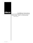
Figure L
H-Series Drive
CORVUS DEALER SERVICE
General Description
CHAPTER 1
GENERAL DESCRIPTION
1.1
Scope of Chapter
This chapter outlines the purpose of the Corvus Systems ™ H-Series ™ Model 6, Modellland Model20disk drives. A
Brief description and layout is include, as is a definition of Winchester technology.
Introduction
This document contains instructions for maintenance and repair of the Corvus Systems H-Series, 5. 25-inch disk drive.
Repair procedures for A-series (8-indl, II-megabyte Rev A) drives and B-series (8-inch, 11- and 20-megabyte Rev B,
and all non-H-Series, 5.25-inch, 6-megabyte) drives as are networks and other Corvus equipment. Corvus (tm) Level I
Dealer Service is on a modular replacement basis, and this manual is written to address this policy.
1..2
The H-Series drives are manufactured in three capacities: 6-megabytes (Model 6), 12-megabytes (Model II), and
18-megabytes (Model 20). These drives all use the same grey high-impact foam-injection plastic cabinet. This is the
same drive enclosure used by several of the B-series, 5.25-inch, 6-megabyte drives. Checking the serial number will
identify the type of drive to be serviced. Instructions for troubleshooting and repair for all H-Series drives are detailed
in this document.
Also included in this manual is documentation on the Dealer Service Diagnostic Utilities supplied to each Corvus
Servicing dealer. These utilities provide for burn-in/reliability testing, adjustment, and troubleshooting of all Corvus
disk drives. The initialization and diagnostic utilities for the H-Series drives are unique to the H-Series, and contain
software specific to these drive models. Use the appropriate A-, B- and H-Series software only for the proper drives.
Installation and operation of the disk drive are not covered in detail in this manual. For instructions in installation and
operation, see the Corvus "Disk Systems Installation Guide" and Corvus "Disk Systems User Guide."
1..3
Purpose of Equipment
The Corvus disk drive is a high-speed, intelligent mass-storage peripheral disk device designed to provide the host
microcomputer with storage and ret rival of digital information instantly at the request of the host system. The Corvus
disk system consists of the 5.25-inch disk mechansim, a Z_80™ intelligent controller and power supply, and may be
ordered with a host interface, 34-pin interface flatcable and Corvus Utility diskettes.
1.4
Model Identification
The three Corvus H-Series disk drives are identical, differing only in the internal layout of the drive sealed mechansim.
The Model 6 uses one platter, the Model 11 uses two, and the Model 20 uses three. The drive type, capacity, and
manufacture date may be determined from the serial number tag located at the rear of the drive cabinet.
The following is a sample serial number to be found on a Corvus H-Series, Model 11 disk drive:
023-BH350/M
and is decoded below:
02
3
B
H
350
/M
represents the week of manufacture (week 02)
represents the year of manufacture (3 for 1983)
represents a Model 11 drive (A=Model 6, C=Model 20)
represents an H-Series drive
represents the serial number of that years' manufacture
represents that this drive was shipped with a Mirror™ installed internally
Whenever communicating with Corvus in reference to Corvus products, include the serial number of the equipment
involved.
"'Corvus Systems is a registered trademark of Corvus Systems, Inc.
"'Mirror is a registered trademark of Corvus Systems, Inc.
™H-Series is a registered trademark of Corvus Systems, Inc.
TI'Z-80 is a registered trademark of Zilog, Inc.
1
General Description
CORVUS DEALER SERVICE
The Corvus Disk System
The Corvus Mass-Storage Disk System utilizes a sealed 5.25-inch Winchester disk mechansim manufactured by
International Memories, Inc (lMI). The drive, with its intelligent controller, is designed as a plug-in device, requiring
minimal software setup. Interfacing to host computers is via 34-pin flat-cable interface. Installation and setup
procedures are covered in the corresponding "Disk System Installation Guide" and "Disk System User Guide" for the
appropriate computer system.
1.5
All H-Series drives consist of a 5.25-inch drive mechansim (with integral Read/Write PCA) and Motor Control PCA,
single power supply, Z-80 Controller PCA, and cooling fan mounted in a grey plastic cabinet.
The Mirror PCA (when installed) and Z-80 intelligent Controller PCA are plugged into the two card slots of the
backplane, located inside the top cover.
1.5.1
Power Supply
All H-Series drives operate from either 110-120YAC or 220-240YAC, 50Hz or 60Hz single-phase power, and use a
single power supply. These power supplies are interchangable between all H-Series drives.
1.5.2
Data Backup
Data backup is accomplished via the Corvus Mirror™. The Mirror converts the data from digital format to video
format which is then stored on video cassette tape, using one of many commercial YCRs. The Corvus Mirror option
comes internal to the drive when it is ordered, or added as an external device later. All Mirrors are available with a
software-controlled, remote-control interface to a Panasonic™ YCR model NY-8200. Mirror troubleshooting and
repair is covered in the Corvus Mirror Service Manual.
Winchester disk drive
The Corvus disk drive uses the IMI Winchester disk mechansim. This new generation of disk drive utilizes a sealed
environment, and low-load, low-mass, aerodynamically-suspended read-write heads which rest directly on the disk
surface after power-down. It is the contaminant-free environment that allows for reduction in clearance between head
and recording media. This results in the heads riding on an 18-micro-inch air bearing, or air cushion. Since bit density is
closely related to head-media clearance and head mass, disk drives utilizing Winchester technology can achieve large
storage capacities at a premium of space. An added advantage of the Winchester sealed mechansim is that it requires no
regular maintenance.
1. 6
™Panasonic is a registered trademark of Panasonic, Inc.
2
CORVUS DEALER SERVICE
CHAPTER 2
INSTALLATION
CORVUS DEALER SERVICE
Installation
CHAPTER 2
INSTALLATION
2.1
Scope of Chapter
This chapter discusses installation of the disk drive hardware as it applies to environmental requirements, to insure
proper operation. Installation and operation procedures for the Corvus disk system are outlined in the "Corvus Disk
Systems Installation Guide" and "Corvus Disk Systems User Guide."
2.2
Introduction
Each drive, when it is received, should be checked for shipping damage, and tested for proper function. This chapter
contains these check-out procedures as well as those for installing single drives and multiple-drive systems.
2.3
Receiving a Drive
Any time a drive is received, several checks should be performed before the drive is installed at the customer site. Each
Corvus disk drive should be carefully unpacked and checked for shipping damage. External evidence of rough handling
may be symptomatic of damage to fragile mechanisms within the drive.
NOTE:
Any damage claims must be reported to the local office of the shipper so an inspection may be made, and a damage report filed.
Also, if the damaged equipment is a new product, Corvus Order Processing Department must be contacted for proper return
procedures. If the damaged equipment is a recently serviced product being returned under an RMA number (Return
Merchandise Authorization number), contact Corvus Customer Service Department for proper return procedures.
The disk drive mechanism in the Corvus disk system is an extremely sensitive device. Subjecting the drive to a one-g
force (one gravity) will be amplified and transmitted to the heads, impacting them onto the platter with a 100-g force.
This necessitates very careful handling of the drive mechanism both in shipping and operation.
When a drive is received, check that all chips in the 2-80 Controller PCA are seated well in their sockets. Chips coming
loose during shipping account for a percentage of the failures upon reciept.
1)
Remove the two screws securing the cabinet cover to the drive basepan at the rear, and remove the cover. Be
careful not to stress the dc power cable and flatcables connecting to the Controller PCA and Backplane PCA.
2)
Locate the Mirror PCA (if installed) plugged into the lower of the two card slots of the backplane, and remove it.
3)
Locate the Controller PCA installed behind the Mirror PCA, and press firmly on all socketed chips, seating them
securely into their sockets.
4)
Replace Mirror PCA.
5)
Replace drive cover and secure with screws.
2.3.1
Diagnostic Test
Upon reciept of a disk drive, several procedures must be exercised to verify the proper functioning of the equipment:
1)
Verify front bezel switch positions
2)
Verify Mirror Switch positions (on rear bezel)
3)
Check Controller Firmware VERSION
4)
Check power supply Voltages
5)
Execute CRe Test
6)
Check Parameters (drive and MUX) and record on paper
7)
Execute EXERCISE Utility
3
CORVUS DEALER SERVICE
Installation
8)
Run BURN-IN Diagnostic (destructive to data)
9)
Update Controller Firmware (drive Diagnostic option UPD) changing tables when prompted (answer "yes")
Any Corvus disk drive may be ordered with a Corvus Mirror PCA installed. In all S.2S-inch drives, the Mirror PCA
plugs into the Backplane PCA alongside the Controller PCA, inside the cabinet cover. The drive has four DIP switches,
located on the rear of the cabinet, which MUST be set to correctly reflect the internal Mirror configuration (whether
installed or not). If these switches are not set properly, the drive may not function properly (refer to the chart below for
proper switch configuration). Drives using a Mirror externally should use the "No Mirror Installed" switch
combination.
1
2
3
~~~
234
4
Pushed in
OPEN
~~
OPEN
DRIVES WITH NO
MIRROR OR EXTERNAL MIRROR:
DRIVES WITH
PAUSECAM MIRROR:
2
3
4
~~~
OPEN
DRIVES WITH
NTSC MIRROR:
The shaded area indicates that the switch should be pushed in on that side.
Figure 2. Mirror Configuration Switches
Check the drive power supply voltages and adjust if necessary (refer to Chapter 6, "Adjustments and Maintenance" for
details).
Next, thoroughly test the drive, using the Dealer Service Diagnostics (as outlined in Chapter 7 "Diagnostics" of this
manual). Execute a CRC-Format Check, as well as verify the drive Parameters (specifically the Spare Track table and
the Virtual drive Offset table). If either of these tables display values out of range, use the PARAMETERS diagnostic
utility to reset them to their appropriate values.
A new drive may be shipped with up to twenty-four tracks spared. There are a total of thirty-one spare tracks available
on a new drive, which leaves a minimum of seven (and most likely more) for use in the field. When the drive
Parameters are first checked, the values should be noted, recorded on a label, and attached to the drive for future
reference.
In the event that the drive format is disturbed in shipment, it may be necessary to reformat the drive. The FORMAT
utility should be used only as a last resort. Using the PARAMETERS diagnostic utility, first try to restore the drive
parameters before attempting the FORMAT utility. The format program will restore default parameters to the drive,
and therefore necessitate re-initialization of these parameters with the original values (i.e. previously spared tracks).
Default parameters are:
Spare Track table:
VDO table:
no tracks spared
Model6 drive 1 = 0
Model 11 drive 1 = 0
Model 20 drive 1 = 0
(drive 2 = 911 must be added after FORMAT)
Interleaving Spec:
all H-Series drives = 9
Be sure to check the drive parameters before and after formatting the drive. If the drive has ever had a track spared, the
Spare Track table and VDO table may need reconstructing before the data is restored. Knowing what tracks are spared
prior to formatting the drive will simplify this procedure. Note on the label, any future tracks spared.
4
CORVUS DEALER SERVICE
2.4
Installation
Environmental Considerations
All electronic equipment needs cooling and the Corvus disk drive is no exception. When installing, do not "pigeon-hole"
the drive. There should be sufficient open area both front and rear. Place the drive on a level, hard surface without
cushion or carpet; the air intake slots are on the bottom of the cabinet, and must not be restricted. Do not place a video
monitor on top of, or near the Corvus drive. Electromagnetic fields generated by this device may cause drive
malfunction.
Be sure the proper line voltage has been selected and proper fuse size is installed.
Insure the interface cable is properly connected between the connector on the interface card in the host computer, and
the PROCESSOR connector on the rear bezel of the Corvus disk drive cabinet. Be sure the "one" edge (edge with dark
stripe) is to the right, when facing the rear of the drive unit.
Connects to
Video Remote
Control
VIDEO
IN
Connects
to Video
Recorder
VCR REMOTE
OUT~
0
Connects
to Interface
Card
•
Mirror Dip Switches
,:
Connects
to Add-on
Drive (If any)
Air Flow Slots
PROCESSOR
:I
DRIVE
Bi
:1
III
0
Power Switch
Connects
toAC Cable
Figure 3. Rear Bezel
Check that all four front panel switches are in the correct position. Run your finger along from right to left, under the
switches. All switches should be to the left, unless the disk drive is connected to a Corvus Multiplexer Network system,
or to a DEC™ LSI-11™ computer. If so, the appropriate switches should be set.
Locate the power switch on the rear of the drive, and turn it on. The drive motor will begin to spin, and all LEOs (front
bezel Light Emitting Diodes) will come on, and the BUSY LED will flash regularly. After approximately thirty seconds,
the FAULT LED will go out, and the heads will rezero. LED activity will briefly alternate between READY and BUS~
after which the drive will set the READY signal, and all LED activity will cease, with the READY LED on. The disk
drive is now ready for communication with the host system.
2.S
Daisy-Chaining of Disk Drives
A maximum of 80 megabytes of on-line storage may be achieved by daisy-chaining four Model 20 drives. This is
accomplished by using a common input/output interface bus, commonly referred to as daisy-chaining. A special
Corvus add-on drive flat cable is available specifically for this purpose. One add-on drive cable is required for each
additional disk drive in the system. All series and Versions of disk drives may be daisy-chained together with the
exception of the Rev A, 8-inch 11MB disk drive (Rev A drives may be daisy-chained only to other Rev A drives). All
must use Controller Firmware version CF18.3 or later.
™DEC is a registered trademark of Digital Equipment Corporation
™LSI_ll is a registered trademark of Digital Equipment Corporation
5
Installation
CORVUS DEALER SERVICE
Changing the unit-select switches (positions 1 and 4) on the drive 2-80 Controller PCA for each add-on drive is
required when daisychaining drives. New drives are shipped with the switches configured as drive 1. Additional drives
should be set according to their position in the daisy-chain (2, 3 or 4). Refer to the Corvus "Disk System Installation
Guide" for the appropriate computer system.
For complete installation and initialization procedures, refer to the appropriate Corvus "Disk System Installation
Guide" and "Disk System User Guide."
~7
t'/
12345678
~HHHH--¥V
DRIVE ADDRESS 1
~
,,/---------t'/
1
234
5
6
7
8
o~
iffnlTln V
DRIVE ADDRESS 2
,,/----------1"/
1
234
5
6
7
8
~HHHH/
DRIVE ADDRESS 3
,c./---------t'/
1
234
5
6
7
8
~HHHH___IV
DRIVE ADDRESS 4
~
Figure 4.
Controller Address Switches
6
CORVUS DEALER SERVICE
CHAPTER 3
OPERATION
--------------------------------_._-----------------------._--_.-.-
CORVUS DEALER SERVICE
Operation
CHAPTER 3
OPERATION
3.1
Scope of Chapter
This chapter describes operator controls and their use as applies to troubleshooting and repair of the drive. Front bezel
control switches and Light Emitting Diodes are described, and their functions detailed. Environmental requirements
are discussed, and recommended regular checks for the drive are given.
Operation and initialization instructions are detailed in the Corvus "Disk System User Guide" for the appropriate host
operating system.
3.2
Introduction
All Corvus S.2S-inch, H-Series drives have front bezel indicator lights and function switches. The switches must be set
properly reflecting the system configuration in order for the drive to function properly. Indicator LEOs on the front
bezel display the state of the drive, and help in diagnosing the condition of the drive at any time.
3.3
Controls
Operator controls are located on the front bezel of the enclosure. Three LEOs monitor the current state of the drive
controller. Four function switches are located under the LEOs. Rear bezel components consist of fuse and power
selection unit (CORCOM), power switch, video connectors, Mirror configuration DIP switches, connectors for host
processor, daisy-chained drive, and remote control VCR interface cables.
3.3.1
Front Bezel LEOs
The LEOs are labled READ'Y, BUS'Y, and FAULT During the power-up sequence all LEOs are on, and BUSY blinks
while the drive motor reaches operating speed. After the drive has completed the power-up sequence, the READY
signal will be set, the READY LED will be on, and the BUSY and FAULT LEOs will be off.
During normal operation, the READY LED is active when the drive is ready to receive a command from the host
processor. The BUSY LED is active when the drive is currently executing a command received from the host processor.
The FAULT LED is active when command execution has been interrupted due to the occurence of an error. The FAULT
LED is an indicator of drive malfunction or operational error, although some software may cause this LED to light
during normal operation. FAULT LED function is accompanied by an error code displayed on the computer
screen.
3.3.2
Front Bezel Switches
The function switches are located below the LEOs on the front bezel. These are (from left to right) LSI, MUX,
FORMAT, RESET During normal operation, in a single-user system without an LSI-II computer, all switches should
be set to the left.
All switches except for the RESET switch are polled by the controller ROM routines to determine system
configuration. Only the RESET switch directly affects the hardware.
Located furthest to the left, the LSI switch is a two-position switch; the OFF (left) position is the normal position, the
ON (right) position is for use with a DEC™ System LSI-II™. At power-on time, the controller polls this switch to
determine if a DEC LSI-II computer is attached, and loads the DEC RLOI™ and RLO2™ disk drive emulation routines
from the Controller Firmware area into controller RAM.
The next switch, the MUX switch, is also a two-position switch; the OFF (left) position is the single-user position, the
ON (right) position is for use with the Corvus Multiplexer Network™. At power-on time, the controller polls this
switch to determine if a Multiplexer is attached, and loads the the Multiplexer polling routine from the Controller
Firmware area into controller RAM.
TO'DEC RUn and RLo2 are registered trademarks of Digital Equipment Corporation
TI·Corvus Multiplexer Network is a registered trademark of Corvus Systems, Inc.
7
CORVUS DEALER SERVICE
Operation
LSI-11
LSI-11
MUX
Multiplexer
Format
Reset
Figure 5. Front Bezel Configuration Switches
The FORMAT switch is a two-position switch; left position is OFF (norma!), right position is ON. This switch serves
two functions. First, when the drive is turned on, the controller checks all front bezel switches. If the FORMAT switch
is ON (right) at this time, the drive will come READY if the ROM-based self-test completes successfully. If, however,
this switch is OFF, the controller reads the Controller Firmware from cylinders 0 and 1 into the on-board controller
RAM. If this procedure is successful, the controller sets the READY signal, and the READY LED is lit, and the BUSY
and FAULT LEOs are extinguished. The drive is now ready to accept a command from the host system. Secondly, the
FORMAT switch must be on for the diagnostic program F)ORMAT to execute (see chapter on DIAGNOSTICS). In
this mode the switch acts only as a hardware safety switch. No one may execute the F)ORMAT program without
having physical access to the drive. The switch being turned ON alone will not format the drive. Only the combination
of the format software and the FORMAT switch will allow one to format the drive. If this switch is ON during normal
operations, communication between the drive and the host system may be impaired.
Located furthest to the right, the RESET switch is a spring loaded, momentary-contact toggle switch. Toggling this
switch initiates a reset signal which resets the intelligent controller in the drive to its original power-on state: the heads
re-zero and disk Controller Firmware is again loaded in from the disk into the controller RAM. The drive is then ready
to accept another command from the host processor.
3.4
Power-On Sequence
No specific sequence need be followed when powering on the Corvus disk system, with one exception. If the Corvus
disk drive is used with an OMNINET local network, power on the Disk Server first. Next power on the disk drive, then
the host computer. This procedure supersedes all other procedures that may be found in previous Corvus publications.
3.5
Environmental Requirements
All working environments contain possible hinderances to proper operation of electronic equipment. The following
are some possible environmental problems and their solutions.
3.5.1
Static Electricity
Static voltages of thousands of volts can be generated in most office environments. If a system shows irregularities
whenever an operator comes in contact with the host computer, network or peripheral equipment, supporting table or
surface, static should be suspect.
8
CORVUS DEALER SERVICE
Operation
Static is most easily generated in a cool and dry enviromnent, usually associated with cold weather. Since increased
humidity helps prevent static electricity buildup, some type of humidifying device can be helpful. Ideal relative
humidity is 70 percent to 75 percent.
3.5.2
Line Noise
Electrical noise on the power line is a major cause of inconsistent equipment operation. Voltage spikes, "brownouts"
and dropouts as well as low line voltage are just some of the common causes of drive malfunction.
Located in the CORCOM power selection unit is a line filter capable of handling most minor electrical noise on the
power line. Also, the power supply is capable of handling dropouts of up to three complete power cycles.
If power is suspect, the problem may lie in poor continuity of the building wiring, noisy or high power-consumption
devices on the same circuit, or poor external supply to the building. Power can be improved by including a constant
voltage regulator or isolation transformer in the power circuit. The constant voltage regulator will help minimize the
effect of line voltage fluctuations on the Corvus drive, while the isolation transformer will be effective in protecting
the Corvus drive from line noise caused by other high-load electrical equipment such as photocopy machines, heating
and cooling equipment, elevators, etc. To lessen the impact of frequent power interruption, the use of an
uninterrupted power supply (UPS) is recommended.
Temperature
Although in most environments, the disk drive needs no actual warm-up time, there are temperature limits that the
drive must operate within (see "Specification" at beginning of this manual). The temperature change maximum for the
Corvus disk is 15 degrees fahrenheit per hour.
3.5.3
3.6
Periodic Maintenance
Inherent in the design of the Winchester technology disk devices, is the freedom from the need for regular preventive
maintenance. The sealed disk mechanism of the Corvus disk drive requires no maintenance, and contains no
field-serviceable components.
CAUTION:
Since contamination of the atmosphere In the mechanism necessitates replacement of the unit,
removing the cover to the sealed mechanism voids all warranties.
3.6.1
Regular Checks
Power supply voltages will change with time, and should be checked periodically. Each time the Corvus drive cabinet is
opened, check the power supply voltages to verify that they are within specified tolerances (refer to chapter 7 for
adjustment procedures).
Due to slight oxidation build-up on cable connectors and IC pins, reseating the flatcable and power connectors and
socketed controller ICs periodically will also help insure reliability.
9
CORVUS DEALER SERVICE
CHAPTER 4
DRIVE DESCRIPTION
CORVUS DEALER SERVICE
Drive Description
CHAPTER 4
DRIVE DESCRIPTION
Scope of Chapter
This chapter provides a description of the Corvus S.2S-inch, Model 6, Model 11 and Model 20 disk drives and their
component interactions. Some terms are defined to help provide a foundation for the following descriptions.
4.1
4.2
Introduction
The Corvus H-Series drives are functionally identical except for the drive capacity. They are:
Model 6:
Model 11:
Model 20:
S.6MB
12.8MB
18.3MB
Each drive is divided into three modules. power supply, disk sealed mechanism, and controller electronics. The
individual components of these modules are:
-
Disk sealed mechanism
Read/Write PCA
Motor Control PCA
power supply or Supplies
Backpla~e PCA
Controller PCA
Paddleboard PCA
Drive Cabinet
All drive components of the H-Series drives are identical and are completely interchangible. These are the minimum
accessable modules and are offered as replacement parts as listed above. No sub-assemblies are available as spares.
4.3
Drive Layout
The H-Series drive retains the high-impact plastic cabinet of the 6-megabyte Rev C through Rev E drives, but uses
many new internal components. The new drive sealed mechanism can be identified by its aluminum casting (as
opposed to the B-Series 6MB molded plastic drive mechanism). Mouted beneath the drive mechanism is a Read/Write
PCA and a Motor Control PCA. These are also compatible between all three drive capacities.
The power supply is a single unit, supplying +12V and +sV It is completely compatible with all H-Series drives.
The H-Series Backplane PCA is attached to the drive cover via standoffs. The Backplane PCA has two card slots which
accept the Controller PCA (nearest the cover) and the Mirror PCA (when installed). The H-Series backplane is
common to all three H-Series models, but cannot be interchanged between other S.2S-inch drives.
The Controller PCA is located in the uppermost slot (nearest the cover) of the drive Backplane PCA. This PCA is
common to all three H-Series models, but cannot be interchanged between other S.2S-inch drives.
The Mirror PCA used with S.2S-inch drives is interchangable between all Revisions of the H-Series drives as well as all
other S.2S-inch drives.
The front bezel Paddleboard PCA is the same PCA used in all revisions of the S.2S-inch drive and most versions of the
B-inch drives, and is interchangable between these drives.
Power Supply
Every Corvus H-Series drive comes with a power supply to provide all voltages required by the drive mechanism and
drive electronics. The H-Series drives require only +12V and +sV The CPS12 is the only power supply required by all
H-Series drive models.
4.3.1
10
CORVUS DEALER SERVICE
Drive Description
4.3.2
dc Power Cables
All power supplies connect to a dc power cable which then connect to the disk mechanism and the drive Backplane
PCA. All dc power cables attach to solder terminals on the power supply PCB. The H-Series drives use power cables
which connect the single power supply to the Read/Write PCA on the underside of the disk mechanism, and to the
Backplane PCA.
4.4
General Description
The recording media of the Corvus 5. 25-inch Winchester disk drives consists oEan nickel-oxide coating on aluminum
disks called platters. There is one 5.25-inch platter in the Model 6 H-Series drive, two platters in the Model 11 drive,
and three in the Model 20. All platter surfaces are utilized for data storage. One head rides above each surface on an
18-microinch air bearing (air cushion).
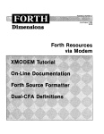
Data is stored magnetically on circular tracks, which are configured as concentric circles on each platter. Each track is
further divided radially into 20 sectors, each sector containing one 512-byte block available for user data. The term
track refers toa single head surface of a cylinder, each cylinder consisting of all tracks in common vertical alignment on
all surfaces. There are 306 cylinders on the H-Series drives, with cylinder zero located furthest from the platter center.
/
" .....
.... ------
--
~,
I
I
.........
)
/1
-
-------
I
I
I
- -
-
-
-
-
1-
....... 1
-
TRACK
CYLINDER
)
.;'
--------
figure 6. Data Configuration
A block is the smallest addressable unit within the drive. Internally, each block consists of 512 bytes of data. Externally,
the drive handles data in sectors as defined by the host computer.
Typically, each host operating system defines a sector as 128 bytes, 256 bytes or 512 bytes. The Corvus interface
software uses the appropriate read and write commands (one each for writing and reading 128, 256 or 512 bytes)
depending on the requirements of the operating system.
This does not cause a conflict, since the drive simply stores 1,2 or 4 host-defined sectors for each disk drive block. Read
and write commands of less than 512 bytes are transparent to the host system, due to the intelligent controller's ability
to handle data blocking internally.
11
CORVUS DEALER SERVICE
Drive Descri ption
Disk Sealed Mechanism
The Corvus mass-storage disk mechanism uses a combination of both new Winchester technology and traditional disk
design.
4.5
The S.2S-inch platters revolve on a common spindle, driven by a brushless dc motor at 3600 RPM. Motor speed is
monitored by the Motor Control PCA, located uppermost beneath the drive mechanism, and is independent of line
frequency. The index pulse is generated by the magnetic index detector mounted to the underside of the drive base
near the spindle. The Solenoid Brake is also located adjacent to the motor hub, and engages immediately after the drive
is powered off. Adjustment procedure for the Solenoid Brake and index detector are located in the section titled
"Adjustments and Maintenance."
Each head is suspended above the platter surface on an 18-microinch (.4S72 microns) air bearing. A particle of smoke,
dust, or a human hair could easily play havoc with with these critical tolerances, and cause catastrophic failure of the
disk device. The seal on the drive mechanism prevents this from occurring by keeping the internal atmosphere
contaminant-free. Breaking this seal for any reason, voids the warranty.
There are two heads for each platter in the drive mechanism. The heads are held by flexure arms, attached to a
common head stack casting which moves on precision bearings and stainless steel rails. Positioning of the heads over
the appropriate cylinder is accomplished by a four-phase stepper motor, via a split stainless steel band. Seeking to a
specific cylinder is accomplished by stepping the motor through four phases for each cylinder. Reversing the sequence
of these motor phases will result in reverse head movement. Each increment of the motor is equal to 0.9 degrees
rotation.
Two Printed Circuit Assemblies are Mounted beneath the drive mechanism. These are the Read/Write PCA and the
Motor Control PCA. The Motor Control PCA is responsible for monitoring the spindle motor speed and altering it as
necessary. Index and track 0 signals are also buffered on this board. The Read/Write PCA, contains a 6801
microprocessor IC which makes the drive mechanism itself an intelligent device, freeing the 2-80 controller from
many rudimentary tasks. The Read/Write PCA sends data to and receives data from the drive mechanism and the
Controller PCA. Many motor control signals are also generated on the Read/Write PCA.
4.6
Controller Firmware
Corvus reserves the first two cylinders of the drive for special code. This is referred to as Controller Firmware, and is
not accessable to the host operating system. This Firmware contains programming and system information required
by the Z-80 drive controller and is loaded into the disk drive RAM when the drive is powered on or when the RESET
switch is toggled. The spare track table, Multiplexer parameters, Semaphore and Pipe information are contained in the
Controller Firmware. Identical copies of Firmware reside in each of the two cylinders. The rest of the disk area is
available to the host system for data storage, the configuration of which depends upon the type of host operating
system. Only Controller Firmware version CF18.3 or later may be used with H-Series drives.
When daisy-chaining one or more H-Series disk drives, it is necessary to update Controller Firmware on all drives in
the system using the latest version of firmware data file (CF18.3 or newer).
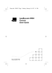
Data Storage
Data storage arrangement is by concentric tracks vertically aligned as cylinders. Each track is sectioned into 20 sectors,
each sector has a data capacity of one S12 byte block. Logical sectors are numbered by using an interleaving
specification (sector skewing scheme) of nine for all H-Series drives.
4.7
All surfaces are used for data storage. Since this drive uses a stepper motor for head positioning, no servo tracks
are required.
Contained in the head stack is the microchip. This select microcircuitry is responsible for selecting which head is being
used. The microchip is also responsible for preamplification, and transmitting of the signal to the drive electronics for
further amplification.
12
Drive Description
CORVUS DEALER SERVICE
TOP COVER
STEPPER MOTOR
LINEAR ACTUATOR
BEZEL
AIR FILTER
-..,#£~ READ/WRITE
Figure '7.
Drive Mechanism Components
13
BOARD
CORVUS DEALER SERVICE
Drive Description
I
: 13
,
,
I
\
\
I
'I
17 "
'\
............ _ "
2
I
I
I
1/
I
6 ',
I
/
/
11
","
,/
/,
__
SECTOR
"0
. . - "Q"
\ ,,-1:---==:= ·:· =:~---198
_-~.-
"
I , /1 ",,,,/
",,"// I
/
I
10 ",'" / I
1
'"
1
"1 /
,
/
I
/ 12'
I 3
Figure 8.
\ , ' ... ,
I
\
\
I
\
1
\
I
I
I
I
I
__
.......................
,
\
\
\
',7
,
16'
\
5 '
\
\
\
14 \
Sector Interleaving
4.8
Transportation Considerations
All Corvus H-Series, 5. 25-inch disk drives have the capability of having the heads "parked" off of the data area of the
platters. Refer to the chapter on "Diagnostics" in this document for the head parking procedure.
Parking the heads in this manner does not preclude the drive from the need for gentle handling. The disk drive is a
delicate instrument. If, when the drive is transported, it is subjected to rough handling, the heads will impact the disk
surface, possibly causing damage.
4.9
Theory of Operation
All communication between the drive and the host computer system is interfaced by the Controller Firmware, resident
in the controller RAM after the drive is powered on. Without firmware the drive will not recognize commands sent
from the host system.
The Corvus drive responds to a small list of commands generated by the disk interface software, which are patched
into the host operating system when the drive is first initialized. These normal commands are:
Read 128-, 256- or 512- byte sector
Write 128-, 256- or 512- byte sector
Enter Prep Mode (download special firmware to RAM)
Mirror (Backup, Identify, Verify, Restore and Remote)
Semaphore (Lock, Unlock, Retry, and Error report)
Read Drive Parameters (Spare Track and Mux table)
Pipes (Initialize, Open, Read, Write, Close and Purge)
All normal drive operations are accomplished using the above commands, as the Controller Firmware contains all Z-80
routines for decoding these commands. Other commands are possible, and are accomplished by first executing the
Enter Prep Mode command which replaces Controller Firmware with special firmware containing routines for
decoding these commands (i.e. diagnostics).
4.9.1
Power-Up
As soon as the power supply voltages have stabilized, the Z-80 controller board executes a ROM routine which
initializes the Z-80 microprocessor and then tests the controller RAM and ROM. If the self-test fails, the Z-80 halts
execution, leaving the FAULT and BUSY LEOs on, and READY LED off.
14
CORVUS DEALER SERVICE
Drive Description
MFM
.-READ DATA
-
~
READ
LOGIC
,.....
~
HEAD
SECTION
LOGIC
•
---[]
HUB
BRACE
WRtTE_GA!~
MFM
WRITE DATA_
-
i
-REDUCE 'WRITE CURA
.- READY
I
:::J
~
I
-L-- _ _ _ _
~
DC HUB MOTOA
INDEX
DET.
:::3
::::I
MTA POWER
:TRACK 000
SE Ej COMPl.
I
I
CONTROL
LOGIC
TEPPER A
TEPPER 8
'1:1"'1"1:"
11:1"'1"'1:"
01 RECTION IN_
-
--
SEL.1_
2
=
f _SELECTED!::
.E:
IL
,.....~-
~FORM·I
_ INDEX
WRI!E FAULT
oRIVE
)
~
MOTOR
VELOCITY
-
STEP
I
I
I
-
10
r----...,
~-
WRITE
LOGIC
I
-
-
--
I
I
_I
C
0
.~
=.
-
=-
TRACK 000
DETECT
8TEPPE~
MOTOR
(ACTUAT
)
INDEX
TRACK 000
-I
t
I
I
...J
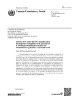
Figure 9.
111111111
R/W HEAD
CONNECTIONS
Drive Mechanism Block Diagram
15
CORVUS DEALER SERVICE
Drive Description
If the self-test executes successfully, the drive begins the controller-boot routine. This consists of first re-zeroing the
heads, bringing them over the first cylinder of the disk surfaces. The front bezel switches are then sampled. If the
FORMAT switch is ON (right), the controller sets the READY signal. If it is OFF, the Controller Firmware is read from
the first cylinder into the on-board RAM. If the Firmware is successfully read in, the drive comes READY If a bad block
(CRC error) is encountered while reading the firmware, the controller will attempt to read from the second copy, any
bad sectors found in the first. It will continue to read alternate copies from the the first two cylinders until all
Controller Firmware is successfully loaded into the controller RAM. The controller will then set the READY signal,
and the READY LED will be on, with the BUSY and FAULT LEOs off.
4.9.2
Controller PCA
The Z-80 drive controller is responsible for interpreting commands sent from the host computer system and
controlling the sub-assemblies (the drive mechanism and associated Read/Write PCA, and the Mirror PCA). The
controller reports back to the Host Computer, via a 34-pin flatcable, the success of the command executed by means of
a one byte return code. A return code of zero is returned if no errors occur. (See Error Code Chart in "Troubleshooting"
section for non-zero return codes).
The Controller PCA contains the 4MHz Z-80A CPU and Z-80A support ICs as well a 4K controller ROM (containing
elementary procedural Z-80 code for the intelligent controller) and 5K of on-board RAM (used for buffering data to and
from the disk, and storing utility code loaded from the Controller Firmware area of the disk). The three Z-80A PIa ICs
are used to buffer signals to and from the host Interface PCA, Corvus Mirror and network devices, drive sealed
mechanism, and the front bezel controller switches and LEOs. In addition, one of the PIa ICs monitors the on-board
CRC generator/checker IC, and informs the Z-80 CPU in the case of a CRC error.
All disk-to-controller memory and controller memory-to-disk data transfers as well as all controller memory-to-Host
Computer memory and Host Computer memory-to-controller memory data transfers are handled by discrete Direct
Memory Access (DMA) circuitry. This DMA state machine is responsible for fast memory transfer during the
execution of read and write commands.
The Controller PCA receives MFM read data from the Read/Write PCA and converts it to NRZ read data before
passing it on to the Host Computer. Similarly, the controller receives NRZ data from the Host Computer and converts
it to MFM format before passing it on to the Read/Write PCA for writing to the disk media.
4.9.2.1
Controller During Seek Commmand
The Host Computer operating system sends a command to the drive controller in a one-, two- or four-byte format.
The controller, using decoding routines contained in the Controller Firmware, decodes the command. The Z-80
microprocessor then calculates the difference between the current cylinder number (always held resident in RAM) and
the requested cylinder. The resultant difference is stored in a RAM memory location and later decremented once for
each cylinder the heads are moved.
Read/Write PCA is then commanded to strobe the stepper motor windings (PHASE A-D). The controller decrements
the cylinder count one for each full motor phase sequence (A-D) and halts the stepper motor at the appropriate
cylinder.. At each cylinder, the controller applies a lock current to counteract the motor's momentum. If the present
cylinder is not the destination cylinder, this current is very low. When the destination cylinder is reached, full locking
current is applied to the motor windings which keep the heads on cylinder.
The next sector to move past the heads is read to verify the success of the seek. If the incorrect cylinder was reached,
the heads are re-zeroed and the seek is attempted again. If the seek fails during this re-try, the drive halts operation,
and a seek error is returned to the host operating system.
4.9.2.2
Controller During Read and Write Commands
The read command begins with the command bytes are received from the Host Computer in parallel form, via the
Interface PCA. This command will be unique for either a 128-, 2.56- or 512-byte sector read. The requested sector
number will accompany the command bytes.
16
CORVUS DEALER SERVICE
Drive Description
STEPPER MOTOR
CARRIAGE
Figure 10.
Stepper Motor Assembly
The controller will calculate a difference value between the current cylinder, and the cylinder containing the
destination sector. The drive mechanism will be commanded to seek to the new cylinder, and the correct head selected.
The controller is now ready to read in the data from the sector, and waits for the appropriate sector to be positioned
under the head. READ GATE is asserted, and the Z-80 relinquishes control to the discrete DMA state machine which
captures the data signal in MFM form from the heads tack microchip via the bi-directional data bus. The data is
amplified, filtered and shaped (squared) before being converted to to NRZ format. The Controller PCA handles CRC
error checking, parallel-to-serial conversion, and transfer of the data to on-board RAM and then to Host Computer
RAM once control is returned to the Z-80. A return code is sent to the host computer identifying the success of the
command.
The drive controller handles data in 512-byte quanties only. Host-defined sector sizes less than 512 bytes are handled
by storing multiple sectors in each 512-byte Corvus sector.
17
CORVUS DEALER SERVICE
Drive Description
Similarly, the write command begins when the command bytes, along with the associated sector address(es} are
received. The Z-80 controller then determines whether the write command is for 128, 256 or 512 bytes (depending on
the host system's standards), and relinquishes control to the DMA circuitry for transfer of the data from host memory
to the on-board controller RAM.
Next, preparations are made for writing that block out to the disk. If the quantity of data to be written is less than 512
bytes, the sector is first read into controller RAM. When the proper sector comes around, the con,troller again turns
control over to the DMA circuitry. The drive processor again is put into a wait state while the DMA transfers data
bytes one at a time to the parallel-to serial converter. A CRC value is generated from the serial data and inserted in the
data stream. The data is converted from NRZ format into MFM format and then directed to the read/write heads for
writing to the sector. The CRC information is used during a read, for checking data integrity.
The disk write operation is concluded by reading in the block and its associated CRC byte to verify its success. Every
write command is followed by a verify (read) command. A status byte is then sent to the host system indicating the
result of the disk write.
4.9.3
Backplane PCA
The Backplane is responsible for transfering power and signals between the Controller PCA, Mirror PCA,
Paddleboard PCA and the Host Interface PCA (via the rear bezel 34-pin connector). The upper slot of the Backplane is
reserved for the Controller PCA, and the lower slot is reserved for the Mirror PCA. These two PCA positions may not
be interchanged.
This two-piece printed circuit assembly accepts flatcables from the front bezel Paddleboard PCA as well as from the
Host Computer System. A single dc power cable supplies voltage to the Backplane PCA via a four-pin connector.
The Backplane PCA for the H-Series drives is unique to these products, and is not interchangeable with other Corvus
drive products. The Backplane PCA for the Model 6, Model 11 and Model 20 is interchangeable only between these three
drives.
4.9.4
Paddleboard PCA
The Paddleboard PCA, located on the front bezel of the drive enclosure contains switches and LEOs. The function of
these controls are detailed in chapter 2.
All Paddleboard PCA revisions are compatible with all drive revisions, and are interchangeable.
4.9.5
Interface PCA
The Corvus disk system will interface to many different microcomputer systems, and may be purchased with any of
several interface cards available.
The typical interface card contains address decoding, bidirectional data buffering, and handshaking circuitry. Some
interface cards also have ROMs containing boot routines for booting the microcomputer from the Corvus disk; some
do not, and these computers must boot from floppy diskette.
Connected to the 34-pin flatcable, the Interface PCA contains two input ports, and one output port and address
decoder. One input port is an eight-bit tristate data buffer, used for receiving data bytes during drive-to-host transfers.
The other input port is the status port, used for determining the state of the disk drive. The output port is an eight-bit
latch, used in host-to-drive data transfers.
When the host system needs to access the disk, it first checks the BUS DIRECTION signal, and if the bus is in the
host-to-drive direction, and the READY signal is high, the drive is ready to accept a new command. The host then
sends command bytes to the drive.
During a read or write command, the bus will remain in one direction without turning around, until all bytes have been
transferred. The drive will acknowledge the acceptance and execution of commands by setting the bus direction bit of
the status port. This is a signal that the return code is on the data bus, which must be retrieved before the drive will
accept new commands.
All of the above handshaking is taken care of by the Corvus interface software and is totally transparent to the user.
18
Drive Description
CORVUS DEALER SERVICE
4.9.6
Read/Write PCA
The Read/Write PCA is located beneath the drive mechanism. The Read/Write PCA is responsible for buffering,
filtering the read data, and supplying write current. Also, the sector and track 0 signals are generated here.
The Read/Write PCA contains a 6801 microprocessor IC, which handles much of the servo motor controt write
current control and most of the drive mechanism control schemes.
The Read/Write PCA is available as a spare parC and is interchangeable between all H-Series drive mechanisms,
regardless of capacity.
4.9.7
Motor Control PCA
Spindle motor speed is monitored by the circuitry on the Motor Control PCA. A tachometer feedback loop helps
maintain spindle speed within 0.5% of 3600 RPM. The magnetic index detector delivers pulses to the Motor Control
PCA, which generates the index signal. The Motor Control PCA monitors this signat and adjusts motor speed as
required.
The Motor Control PCA is available as a spare parC and is interchangeable between all H-Series drive mechanisms,
regardless of capacity.
Two Motor Control PCAs exist, one (p/n 811-02410) for use with the two-wire brake mechanism, and one (p/n
811-01908) for use with the three-wire brake mechanism. Each of these PCAs must be matched with the appropriate
brake mechanism, and may not be substituted for one another.
19
CORVUS DEALER SERVICE
CHAPTER 5
DISASSEMBLY
CORVUS DEALER SERVICE
Disassembly
CHAPTER 5
DISASSEMBLY
5.1
Scope of Chapter
This chapter contains disassembly instructions for all H-Series drives. These three drive models (Model 6, Model 11,
and Model 20) are all physically identical. The disassembly instructions that follow apply to all.
Introduction
5.2
The Corvus H-Series drive consists of a high-impact plastic shell, the top and bottom halves held together with two
screws at the rear of the cabinet. The backplane has two edge-connector slots which accept the Mirror PCA (when
installed) and Controller PCA, and a 20-pin flatcable connector which accepts the cable from the front bezel
Paddleboard PCA. All these are mounted to the drive cover. The drive sealed mechanism and power supply are both
attached to the cabinet basepan.
WARNING:
Before disassembling any disk equipment, be sure the power Is disconnected.
5.2.1
Tools Required
The following tools are required for disassembly of all Corvus H-series drives:
1)
#2 phillips screwdriver
2)
5/64-inch hex driver
3)
3/32-inch nut driver
4)
3/16-inch blade screwdriver
Plastic Package
5.3
The H-Series drives share the grey plastic drive cabinet with the Corvus Rev C, D and £, 6MB disk drives. Disassembly
is similar.
5.3.1
Top Cover
1.
Remove the two phillips screws at the rear of the cover.
2.
Remove the cover by sliding it back and lifting it straight up. Be careful not to stress the dc cabling and flatcables
connected to the Controller PCA and the Backplane PCB.
5.3.2
Controller PCA
1. Remove the drive mechanism flatcables from the upper connectors of the Controller PCA noting their orientation
(one edge to the left).
2.
Note the orientation of the two flatcables (one-edge to the left) connecting the drive mechanism to the Controller
PCA, and disconnect them.
3.
If the drive has a Mirror PCA installed in the Backplane, remove it by gently disengaging it from the standoffs and
pulling it out of the backplane slot.
4.
Remove the two nylon standoffs securing the controller to the cover.
5.
Remove the controller by gently pulling it out of the backplane slot.
20
Disassembly
CORVUS DEALER SERVICE
Backplane PCA
5.3.3
(
1.
Disconnect the one dc power cable and one flatcable from the Backplane, noting their orientation (one edge to
the left).
2.
Release the forward half of the Backplane PCA from the nylon standoffs.
3.
Remove the five nylon standoffs securing the Backplane to the cover.
4.
Remove the Backplane PCA by moving it down and forward.
NOTE:
The ground wire connecting the drive mechanism to the power supply MUST be connnected for the drive to perform properly.
5.3.4
Drive Mechanism
1.
Disconnect the ground wire between the drive mechanism and the power supply.
2.
Remove the four phillips screws securing the drive mechanism mounting brackets to the basepan.
3.
Noting the orientation of the dc power cable and flatcables, disconnect them from the drive mechanism.
4.
Remove the drive mechanism, with its brackets, up and out of the basepan.
5.
Remove the four phillips screws securing the brackets to the drive mechanism, and remove the brackets.
5.3.5
Read/Write PCA
1.
Remove the drive mechanism as outlined above.
2.
Remove the mounting brackets.
3.
Place the drive mechanism on its top, exposing the Read/Write PCA.
4.
Disconnect the read-write/head-select mylar flatcable from the Read/Write PCA to the drive mechanism
(see figure 11.)
5.
Remove the three standoff securing the Read/Write PCA to the drive mechanism.
NOTE:
The central standoff securing the Read/Write peA provides an electrical ground, and must be metal.
6.
Gently lift the Read/Write PCA up, disconnecting the Motor Control PCA connector J-24 (refer to figure 11).
7.
Once the Read/Write PCA is free of the Motor Control PCA connector, swing the PCA up to expose the stepper
motor connector.
8.
Noting the stepper motor cable orientation (yellow wire towards outside), disconnect it.
5.3.6
Motor Control PCA
1.
Noting its position and orientation, unplug the brake mechanism connector (J-21) from the Motor Control PCA.
2.
Noting its position and orientation, unplug the spindle motor connector (J-22) from the Motor Control PCA.
3.
Noting its position and orientation, unplug the index sensor connector (J-25) from the Motor Control PCA.
4.
Noting its position and orientation, unplug the track zero switch sensor connector (J-23) from the Motor Control
PCA. This connector must be rotated 90 degrees from vertical before being re-connected.
5.
Remove the two standoffs and one slot screw, noting their respective positions, and remove the Motor
Control PCA.
21
CORVUS DEALER SERVICE
Disassembly
STEPPER MOTOR CABLE
READ/WRITE AM)
HEAD SELECT CABlE
\
,,//~i·'/)
(/
~ ~
v~
MOTOR CONTROl
BOARD CONNECTOR
STEPPER MOTOR
READ/WRITE BOARD
FRAME
Figure 11. Read/Write PCA Removal
22
Disassembly
CORVUS DEALER SERVICE
SPINDLE MOTOR CABLE
I
MOUNTING SCREWS (2)-----.1
STANDOFF
Figure 12. Motor Control PCA Removal
23
CORVUS DEALER SERVICE
5.3.7
Power Supply
1.
Disconnect the ac wiring harness connector from the rear bezel CORCOM unit and power switch.
2.
Remove the screw securing the ac groundwire to the power supply.
3.
Remove the screw securing the dc groundwire to the power supply.
4.
Disconnect the dc wiring cables from the drive mechanism and the Backplane PCA.
5.
Disconnect the ac fan cord from the cooling fan.
6.
Remove the four phillips screws securing the power supply to the basepan.
7.
Remove the power supply straight up and out of the basepan.
5.3.8
Disassembly
Front Bezel
1.
Remove the flatcable from the front bezel Paddleboard PCA, noting its orientation (one edge down).
2.
Remove the three phillips screws securing the front bezel to the basepan.
3.
Remove the bezel straight forward.
24
CORVUS DEALER SERVICE
CHAPTER 6
ADJUSTMENTS AND MAINTENANCE
CORVUS DEALER SERVICE
Adjustments
CHAPTER 6
ADJUSTMENTS AND MAINTENANCE
6.1
Scope of Chapter
This chapter will cover check and adjustment of power supply voltages, brake solenoid and index detector.
6.2
Introduction
The Corvus disk system is based on a Winchester disk mechanism. Because of this storage device's sealed environment,
the mechanism itself needs no preventive maintenance.
6.3
Power Supply Voltage Check and Adjustment
Aging of the power supply and normal heating and cooling of the drive electronics can cause the power supply voltages
to drift. Voltages should be checked each time the installation is visited for system checkout.
All three H-Series drives use the same power supply, the CPS10, and is interchangible between all three H-Series
drives.
WARNING:
Extreme caution should be exercised when adjusting the power supply. High voltages present a
potential hazard.
6.3.1
Voltage Check (CP510):
1.
Remove cover to the enclosure as outlined in chapter s.
2.
Locate voltage test points at the edge of the CPS10 power supply. These are labeled +12\1, +12V COM, +5\1, +SV
COM.
3.
Turn on the ac power switch.
4.
Using a DIGITAL voltmeter, check the power supply voltages at these connections, using the corresponding
COMMON test point. All voltages must be within ±O.l volts of the specified voltage.
s.
If any of the voltages are out of tolerance, follow the adjustment procedure for this supply.
6.3.2
Voltage Adjustment (CP510):
1.
Remove cover to the enclosure as outlined in chapter s.
2.
Connect ac power to the disk drive, and turn on the ac power switch.
3.
Monitoring the de voltages as outlined above, adjust the +sV and +12V using the following adjustments:
CPS10
R-9
R-16
+12V
+SV
25
Adjustments
CORVUS DEALER SERVICE
Figure 13. CP510 Power Supply
NOTE:
During adjustment, the +sV or +12V may drop to or near zero. This is due to the over-voltage protection circuitry being
activated. To reset this condition, turn off the ac power switch, and bleed the +sV or +12V charge to ground using a 10-K
resistor. Set the trim resistor to its original position, turn on ac power and proceed with the adjustment.
4.
Remove ac power from the drive.
5.
Replace the drive cover and screws.
CAUTION:
Do not manually spin the drive motor at any time.
6.4
Motor Brake Adjustment
1.
Remove the drive mechanism from the cabinet and remove Read/Write PCA as described in Chapter 5.
2.
Loosen the two brake mechanism assembly mounting screws.
3.
Hold the brake solenoid assembly against the lateral location bosses.
4.
Place the appropriate thickness gauge between the brake friction shoe and the motor hub.
3-wire Motor Brake Assembly: 0.007" ±0.003"
2-wire Motor Brake Assembly: 0.012" ±0.003"
5.
While holding the brake plunger fully retracted, move brake assembly against thickness gauge and motor hub, and
tighten brake mounting screws. Do not overtighten these screws.
6.
Recheck the adjustment of the brake mechanism. With the brake plunger fully retracted, the hub-to-plunger
clearance should be as described above.
7.
Reinstall Read/Write PCA.
26
CORVUS DEALER SERVICE
Adjustments
LATERAL LOCATION BOSSES
/
o
~
'''V ··.015 GAUGE
BRAKE CABLE
REGISTER AGAINST
LATERAL LOCATION BOSSES
HOLD PLUNGER
FULLY RETRACTED
Figure 14. Brake Mechanism Adjustment
27
Adjustments
6.5
CORVUS DEALER SERVICE
Index Sensor Adjustment
CAUTION:
Altering of the Index Sensor adjustment may cause loss of data on the drive mechanism. This
adjustment should be attempted only if a backup of the drive data exists.
1.
Remove the drive mechanism from the drive cabinet and remove Read/Write PCA as described in Chapter 5.
2.
Loosen the two index sensor assembly screws.
3.
Rotate motor until the the silver-colored timing tab lines up with the index sensor.
4.
Place a 0.015" thickness gauge between the sensor and the index tab on the motor.
5.
Move the index sensor against thickness gauge and tighten mounting screws.
6.
Recheck the adjustment of the index sensor. With the index timing tab aligned with the index sensor, the clearance
should be 0.015" ±0.003".
7.
Reinstall Read/Write PCA.
28
CORVUS DEALER SERVICE
INDEX TIMING TAB
INDEX SENSOR CABLE
\~EXSEN&m
RETAINING CLIP (2)
MOUNTING SCREW (2)
Figure 15.
Index Sensor Adjustment
29
Adjustments
CORVUS DEALER SERVICE
CHAPTER 7
DEALER SERVICE DIAGNOSTICS
CORVUS DEALER SERVICE
Diagnostics
CHAPTER 7
DEALER SERVICE DIAGNOSTICS
Scope of Chapter
7.1
The Dealer Service Diagnostic Utilities are supplied to aid the technician in tracing faults in the Corvus disk drive
system, and speed the correction of these faults. The Drive Diagnostic, Controller Diagnostic and Track Diagnostic
utilities are covered in this chapter. The Mirror and OMNINET Diagnostics are covered in the service manuals for
those products.
Introduction
7. 2
Each Authorized Corvus Dealer Service Center will be supplied with Dealer Service Utilities. These utilities will help
the technician exercise and diagnose the Corvus disk and network systems.
The Dealer Service Utilities diskette is comprised of standard Drive Diagnostic for the all Corvus disk drives (including
the H-Series drives), Controller Diagnostic which will exercise and diagnose the drive utilizing the drive Z-80
processor, and a rigorous Burn-In program which exercises and tests the drive system infinitely (i.e. overnight). Also
included is a single-track read-write diagnostic, for determining the condition of an individual track.
Some versions of the diagnostic utilities display only 40 characters on the video monitor. When viewing the diagnostic
menu under each specific item, typing a question mark (7) will display an additional 40 characters of menu options.
The latest release of Dealer Service Diagnostics cover all series of Corvus disk drives:
A-Series:
8-inch, 11-MB, Rev A drive
B-Series:
8-inch, 11-MB, Rev B drive
B-inch, zo-MB, Rev B drive
5. Z5-inch, 6MB, Rev A through Rev E
H-Series:
S.Z5-inch, 6-MB (Model 6) Rev A
S.Z5-inch, 1Z-MB (Model 11) Rev A, Rev B
5. Z5-inch, 18-MB (Model ZO) Rev A, Rev B
Diagnose the H-Series drives using only diagnostics specifically labeled as service diagnostics for the H-Series drives.
Previous diagnostics versions (pre-April 1, 1983) will not communicate with the Corvus disk drive properly.
Drive Diagnostics (DRVDIAG)
7.3
This program is essentially the same program provided on the Initialization Utility diskettes supplied with each Corvus
drive. AU options within this program are non-destructive to data on the drive, with the exception of the Format utility.
While the PARAMETERS option of the diagnostic program does not actually destroy data, changing these values using
this diagnostic option will change relative track and sector addresses which will make the data inaccessable.
7.3.1
CRC
A good sector is defined as one capable of retaining all bits in the order they were written. When a block is read from a
sector, the CRC value is read with it and tested. Bit errors may occur due to a bad sector, damaged in one of two ways:
1)
physically (faulty media resulting in dropped bits and mismatched CRC bytes)
Z)
magnetically (miscellaneous bits written to the block resulting in a mismatched CRC value)
30
Diagnostics
CORVUS DEALER SERVICE
The Cyclic Redundancy Code test is a non-destructive test which reads each block of data, and checks it against its CRC
value. If for any reason, the CRC value in that sector does not match the block of data, the CRC checker/generator
signals the controller that an error has been detected, and the processor halts operation. Any errors will be reported at
the end of the program. CRC errors encountered during normal drive operation will halt disk drive operation with the
error code displayed.
Run this test several times to determine whether the error is due to faulty media (where specific sectors will repeatedly
will show errors) or random magnetic bit changes (where sectors will show one-time errors). Tracks containing sectors
with repeated errors should be spared (using Drive Diagnostic utility PRM).
'7.3.2
EXR
The exercise test (EXR) seeks random sectors and reads the header information from that sector to verify the success
of the seek. Periods print to the video display for successful operations, asterisks for hard errors (errors that exist after
ten retrys) and question marks for soft errors (operations that succeed after at least one retry).
Pressing RETURN displays the error list, consisting of total number of passes (seeks), hard and soft errors. Any errors
reported should be followed by a CRC test to check for faulty sectors.
'7.3.3
UPD
This Controller Firmware Update utility rewrites a new copy of Controller Firmware into each of the first two
cylinders of the drive. All H-Series drives must use Controller Firmware version CF18.3 or greater.
Since it is not possible to update the firmware on the boot drive, the system MUST first be booted from another boot
device (another Corvus Drive, or floppy diskette).
The H-Series version of this utility will prompt you with:
Change Tables? (YIN)
A negative answer to this question will not endanger data resident on the drive. Although the UPDate utility is
non-destructive to the data itself, answering affirmatively to this will result in these tables being rewritten with
default values:
Spare Track table
VDO table: Drivel
Interleaving Spec
+ No Tracks Spared
= 0
=9
Be aware that whenever these default table values are written to the firmware area (by answering YES to "Change
Tables ?"), they replace previous values that may have been written at an earlier time. These may include spared tracks,
and virtual drives in addition to the default of 1 drive. If data is resident on the drive when these values are changed, all
relative references to the data (absolute sector addresses) will be changed, and the data will be inaccessable afterwards.
The Format program will also rewrite these default table values.
Next, the program will display a Controller Firmware file name. This will be in the form of :
ENTER CONTROLLER CODE FILE: CFxx.x
The current level of Controller Firmware at this writing is CF18.4AP. If another version is to be used, it should be
entered now. The version of Controller Firmware used on the drive should be none other than that supplied with the
Corvus initialization diskettes that were used when the drive was originally initialized.
'7.3.4
VSN
This utility displays the current versions of the Controller Firmware and controller ROMs:
DRIVE 1: Vxx.x CORVUS SYSTEMS DD-MMM-YY
CONTROLLER ROM VERSION: nn
31
CORVUS DEALER SERVICE
Diagnostics
where DD-MM-YY represents the release date of that Controller Firmware version, xx.x represents the Controller
Firmware version (i.e. CFI8.4AP) and nn represents the suffix of the controller ROM (i.e. 7.63). At this printing, the
current versions are:
Controller Firmware: CFI8.4AP
Controller ROM: 7.63
'7.3.5
FMT
WARNING:
This utility will destroy data on the drive.
Although the Format utility should be used only as a last resort when attempting to reestablish normal drive
operations, the drive may at some time need reformatting. This diagnostic-level, or bottom-level format writes the
rudimentary magnetic pattern to the tracks required before data may be retained properly. This format must be intact
before the drive may be initialized for any operating system or data storage using Corvus initialization software.
First turn the FORMAT to the ON (right) position, then execute the Format utility. Some versions of this utility
request a password, which is HAL When the Format has completed, the program will display:
FORMAT COMPLETE - NOW UPDATING FIRMWARE
ENTER CONTROLLER CODE FILE: CFxx.x
The program will now rewrite the Controller Firmware using the input file displayed. If another version of firmware is
to be used, enter the filename now. Use only the Controller Firmware version appropriate for the drive (see UPDATE
utility above).
The Format program writes default Drive Parameters to the drive:
Spare Track table
= No Tracks Spared
VDO table: Drivel = 0
Interleaving Spec
= 9
and should be updated as necessary after the Format program terminates (see UPDATE above, and PARAMETERS
below).
'7.3.6
PRM
The Parameter option of the diagnostic program allows the checking and alteration of the Constellation Mulitplexer
parameters (including Master Multiplexer Configuration table and Polling Parameters) and Drive parameters
(including Spare Track table, Sector Interleaving Specification and Virtual Drive Offset table)
'7.3.6.1
MUX
Selecting this option displays the Multiplexer table:
M
M
M
M
M
M
M
M
X
As displayed above, the Multiplexer table is not to be altered if the drive is not connected to a Corvus Multiplexer
network, or is connected to a single, Host Multiplexer.
Only if a Master Multiplexer is used in the Multiplexer Network is this table to be changed. In the instance that a
Master Mux is installed, each of the eight ports (M in the above table) should changed to either "N" if no device is
connected to the port, "C" if a computer other than a DEC-System LSI-II is connected to the port, or "L" when an
LSI-II is used, or left an "M" if a Host Mux is connected to that port.
32
CORVUS DEALER SERVICE
Diagnostics
There is only one MUX table, and it should be changed to reflect the configuration of the Master Multiplexer only, or
left unchanged if only a Host Mux is used.
Polling Parameters is the next option of the program. When the drive is used with a Corvus Multiplexer local network
with Intertec Superbrain * or Radio Shack TRS-80* computers, the Polling Parameters should be changed:
Standard Polling parameters: 180,26,32,0
For Superbrain and TRS-80: 180,52,32,0
7.3.6.2
DRIVE
Selecting this option displays the Spare Track table, Sector Interleaving Specification, and Virtual Drive Offset table.
Whenever a track is found to contain a faulty sector (via the CRC test), that track must be removed from service, and a
spare track used. These bad tracks are eliminated by listing them in the Spare Track table. This utility enables the user
to:
ADD a track to the Spare Track table (remove it from use)
DELETE a track from the Spare Track table (restore it to use)
LIST the Spare Track table
QUIT or exit from the spare track routine
By selecting the ADD option, the track number returned by the CRC test (see CRC below) can be entered, thereby
ignoring the track with the erring sector.
The Sector Interleaving Specification is the next option of the program. Interleaving, or skewing, is defined as the use of
an offset constant in the logical numbering of sectors. This value for all H-Series drives is nine for all computer systems
except the DEC System LSI-II which uses a value of five. Sector Interleaving is shown in Figure 8.
Check the Interleaving Specification when the drive is first received, and whenever it is formatted.
Next, the Virtual Drive Offset table should read:
DRIVE 1
0
unless otherwise instructed by the Corvus "Disk System Installation Guide." This table should be checked when the
drive is first received, and whenever the drive is formatted. Model 20 disk drives must be configured as two virtual
Oogical) drives. This is accomplished by adding a second virtual drive, beginning at track 911.
7.3.7
SET
This utility allows the user to change the slot number, drive number, or drive type of the drive to be diagnosed. This
allows the technician to connect several drives to one host computer, and test anyone.
7.3.8
PARK HEADS
Whenever the H-Series drives are to be transported, the heads must first be parked off the data area. The PARK
HEADS command accomplishes this by moving the heads onto a non-critical area of the drive platters. All drive
indicator LEOs will be off after executing this diagnostic option. This indicates that the heads are parked, and the drive
should now be powered off immediately. To restore the drive from the park mode, either toggle the RESET switch or
power the drive on.
7.3.9
QUIT
Selecting this option exits the program, and returns the user to the main Dealer Service menu.
33
CORVUS DEALER SERVICE
Diagnostics
'7.4
Controller Diagnostic
The purpose of the Controller Diagnostic program is to provide comprehensive testing for the Corvus disk drives.
Some of these utilities are designed for use when adjusting the servo mechanisms on the Corvus 8-inch, II-megabyte
and 20--megabyte disk drives, and will not be used with the H-Series drives. These few utilities are included here only
because they are provided on all Dealer Service Diskettes.
'7.4.1
General Description
The Controller Diagnostic program is a combination of 2-80, host system machine code and high-level language
programs which allow the technician to directly communicate to the intelligent controller of the disk drive. The code
breaks down into three parts as follows:
High-level language terminal program: The high-level portion of the program makes the host
computer a semi-intelligent terminal which can communicate with the drive controller. There are
several features implemented in the high-level program, such as base conversions, slot selection and
the driver which downloads the code to the drive controller.
Host system machine code: The machine code provides the low-level interface to the drive controller.
It transmits and receives data from the controller according to the parameters passed to it by the
high-level program. It is slot selectable and contains a one second time-out feature which allows the
program to recover if the drive is not responding.
2-80 code: The 2-80 code is the heart of the diagnostic and is the largest portion of the program. It
performs the commands which are passed to it by the high-level program via ASCII characters. It
consists of three blocks of code which are loaded to different locations in the controller memory.
Controller Diagnostic Commands
The following is a detailed description of each function of the Controller Diagnostic. Please note that there should be
no spaces in the commands unless the notation <space> is specified.
'7.4.2
Whenever the entry of a Controller Diagnostic command results in the response
fIX
(YIN)?"
where x is the command entered, be sure the continuation of this test is appropriate; these commands are destructive
to data.
During normal operation, when an error is encountered, the controller will repeat the operation in an attempt to
succeed. All errors returned by the Controller Diagnostic are reported without retrying the command.
'7.4.2.1
A) ABORT DIAGNOSTIC:
This command allows the operator to leave the diagnostic and return to the command level of the operating system.
The format for this command is:
A <return>
'7.4.2.2
B) MACRO MENU:
This command allows the operator to create a Macro program. The computer will prompt you with:
W)RITE MACRO X)ECUTE MACRO
Enter W to create a Macro program. The format for this command is:
W<return>
34
CORVUS DEALER SERVICE
Diagnostics
The computer will return with the prompt:
ENTER COMMANDS FOLLOWED BY<RETURN>
TO END ENTRY: TYPE 'END' < RETURN>
Enter single-letter Controller Diagnostic commands from this Controller Diagnostic menu, one at a time, each
followed by<return>. The Macro list should begin with the DOWNLOAD command and terminate with "END." The
computer will then prompt you with:
DATA OK?
Entering a "n" will return the Controller Diagnostic command prompt. Entering a "Y" will result in the computer
prompt:
ENTER MACRO FILENAME =>
Enter the name you wish to call the Macro program you have just created (maximum 11 characters). The computer will
respond with:
* MACRO FILE WRITTEN TO DISK *
The Macro file can be executed by selecting "X" from the Macro Menu. The computer will prompt you for the
filename:
ENTER MACRO FILENAME =>
Enter the filename of the Macro program you have previously created, and press<return>. The Macro program will
begin execu bon:
* EXECUTING MACRO ==> xx.MAC *
and finish with:
* END OF MACRO PROGRAM *
A sample Macro program with the name of "TEST" is on the Dealer Service Utilities diskette.
'7.4.2.3
C) CHANGE SLOT NUMBER:
This command allows the operator to change the slot number of the drive under test. The default value is set to slot 2 at
the start of execution. (Note: It is possible to have multiple drives under test by starting execution, then changing slot
numbers. You will have to return to the original slot to view test results.) The format for this command is:
C<return>
The computer will prompt you for the slot number as follows:
ENTER SLOT NUMBER (DEFAULT=2) ?
Enter the slot number desired and press <return>.
'7.4.2.4
D) DOWNLOAD DIAGNOSTIC:
This command must be executed before any of the tests can be performed on the drive. This command loads the Z-80
code into the memory of the drive controller. The FORMAT switch must be on before downloading the diagnostic in
order for the program to function correctly. The format for this command is:
D<return>
35
CORVUS DEALER SERVICE
7.4.2.5
Diagnostics
I) ANALYZE SERVO:
This command allows the operator to measure the seek time of the servo without an oscilloscope. Since the S.2S-inch
drives use a stepper motor servo mechanism which does not require any adjustment, this utility is for use with 8-inch
Corvus drives only. The format of this command is as follows:
I <return>
The controller will perform 2S6 seeks and then report the average seek time in milliseconds. This number should be 70
ms ±2.Sms if the servo is within tolerance (8-inch drives only).
J) SINGLE DO SEEK:
This command instructs the controller to seek to the cylinder specified in the command. It is used to move the heads to
a specific cylinder to observe servo tracks. The format for this command is:
7.4.2.6
ccc.J <return>
where ccc represents the desired cylinder number in hexidecimal. Since the S.2S-inch drive has no servo tracks, this
utility is limited to use on the 8-inch drives.
7.4.2.7
L) FULL CYLINDER LOOPSEEK:
This command instructs the controller to continuously seek from cylinder zero to maximum cylinder. This command
can be used to check servo action and to adjust the servo board (8-inch drives only), or as a general servo exercise utility
for all drives. The Controller will continue seeking until a new command is issued. The format for this command is:
L <return>
7.4.2.8
P) PRINT QUIET SUMMARY REPORT:
This command allows the operator to view the results of the sector quiet, seek scan, read scan and write scan
commands. The results are printed in the following format:
1)
SEEK ERRORS: Seek errors are represented in the following format:
ccc:ddd:ee
where ccc is the desired cylinder in decimal, ddd is the cylinder in decimal which was actually found and ee is the
error code. See the error codes in section 8.4.3.
2)
CRC ERRORS: CRC errors are represented in the following format:
ccc-h xxxxx
where ccc is the cylinder number in decimal, h is the head number in decimal, and xxxx is the number of errors in
decimal.
3)
TOTAL SEEKS: This number represents the number of seeks the controller has performed so far. The number
will be in decimal.
4)
SEEK TIME: This number represents the total time spent performing seeks in milliseconds. The average seek time
can be calculated by dividing seek time by the number of seeks.
S)
RPM: These numbers represent the minimum and maximum speed of the drive during the execution of the sector
quiet diagnostic.
7.4.2.9
Q) SECTOR QUIET PROGRAM:
CAUTION:
This command will DESTROY data on the disk.
36
CORVUS DEALER SERVICE
Diagnostics
This command instructs the controller to begin executing the sector quiet diagnostic. This diagnostic is a very
comprehensive test of the drive media and electronics. The controller performs continuous seeks, reads and writes at
random locations on the disk. The results of this test are obtained by the command documented in 7.4.2.8. The format
of this command is:
Q<return>
The controller will respond with:
Q (YIN) ?
Enter Y <return> to begin the test, enter N to abort. The controller will continue this test until a new command is
issued.
'7.4.2.10
S) READ SCAN DISK:
This command instructs the controller to perform a sector verify pass (CRC check). The results of the scan will be
added to the sector quiet results which are available thru the command documented in 7.4.2.8. The format for this
command is:
5 <return>
The controller will continue to read scan the disk until a new command is issued.
'7.4.2.11
T) SINGLE CYLINDER SEEK SCAN:
This command instructs the controller to single step across the disk. This can be used to observe the servo tracks on the
8-inch drives as the heads move across the platters. The format of the command is:
T<return>
The controller will continue to seek scan until a new command is issued.
'7.4.2.12
X) WRITE SCAN DISK:
CAUTION:
This command will DESTROY data on the disk.
This command instructs the controller to perform a bottom level format of the drive. This will not write Controller
Firmware, it will simply format the entire disk. The format for this command is:
X <return>
The controller will respond with:
X (YIN) ?
Enter Y to write scan the disk, enter N to abort. The controller will continue to write scan the disk until a new
command is issued.
'7.4.2.13
Y) REZERO HEADS:
This command instructs the controller to position the heads on cylinder zero. The format for this command is:
Y <return>
37
CORVUS DEALER SERVICE
Diagnostics
'7.4.3
Error Codes
The errors codes returned by the command documented in 7.4.2.8 are as follows:
00 - Hardware detected fault in read or write
01 - heads move off track while not seeking
02 - seek time out
03 - Phase lock oscillator error (PLO)
04 - sector CRC error
05- cylinder address mismatch
06- read after write verify error
07- guard band detected in data region
08- read sector time out
09 ,- write sector time out
10 ,- bad track list overflow
11 .- sector locate error
'7.5
Burn-In Program
This program is destructive to data on the disk. Be sure a back-up of the data exists before proceeding.
Selecting the Burn-In program will automatically begin the polling of the host computer slots. The program
determines the type of drive in that slot, and the burn-in procedure begins on all drives attached to the host system.
The Burn-In program is a rigorous read-write routine which steps through the drive one chunk (256-sector quantity)
at a time, reading and writing specific patterns to each of the sectors. The program divides the disk media into chunks
by dividing the total number of sectors by 256.
The Burn-In program begins with the highest chunk number. When the read/write test is completed for the current
chunk, a random 256-sector read test is executed over the complete disk drive. When this is complete, the chunk
number is decremented by one, and the test repeats.
The program may be halted at any time by pressing the <return> key or the SPACE bar. This displays a sub-menu:
C)ONT L)IST R)ESTART Q)UIT
''7.5.1
C)ONT
Entering a "C" will cause the program to continue from where it left off.
7.5.2
L)IST
Entering a "L" will cause the error list to be displayed (for example):
*** SLOT NUMBER 2 ****
CURRENT TIME = 0,75
TOTAL ERRORS: 0
HARD ERRORS : 0
SOFT ERRORS : 0
DO YOU WANT A COMPLETE LIST (Y/N)?
Slot number refers to the host slot to which the disk drive is interfaced to. Current time refers to A) the pass number
and B) the current chunk being tested.
Errors are those disk read or write errors which, after 15 re-reads or 3 re-writes, are still in error. Soft errors are those
read or write errors which, after at least one retry, have been corrected. Requesting a complete list will result in a
display of the specific tracks with the error results for each (refer to section 7.4 for detailed information on error codes).
'7.5.3
R)ESTART
Entering an "R" will begin the program again from the beginning. All error counters will be re-zeroed.
38
Diagnostics
CORVUS DEALER SERVICE
7.5.4
Q)UIT
Entering a "Q" will return to the Dealer Service Diagnostic menu.
READ BURN-IN RESULTS
This program allows the burn-in results of all drives to be output to the video display or printer:
7.6
*** SLOT NUMBER n ***
CURRENT TIME = p,cc
TOTAL ERRORS: x
HARD ERRORS : y
SOFT ERRORS : z
[followed by a detailed listing of all errors]
where n is the number of the slot that the drive is connected to, p is the pass number, cc is the current chunk being
tested, and x,y and z are the total errors, hard errors, and soft errors, respectively.
7. 7
Track diagnostic
The Track Diagnostic Utility is a helpful tool for exercising a particular track suspected of having media problems. This
program is destructive to data, and should be used only if a backup of the data exists.
Selecting this option from the Dealer Service Diskette will result in the Slot Number and Drive Number prompts.
Enter the appropriate values. Pressing <escape> will exit the program.
The prompt SERVO ACTION (YIN)? is displayed. If The servo mechanism is not suspect, enter an "N."
For each pass (or "pattern"), the test displays the pattern number, the track being tested, and the beginning sector for
that track.
The Track Diagnostic begins with the a read from the first sector on the specified track. This is followed by a write of a
specific pattern to that sector, and then a verification of the write. If this is all successful, a dot is printed on the screen. If
an error is detected, an asterisk is printed. The test is then repeated on the next sector.
Pressing the <return> key or SPACE BAR will halt the test, and display the submenu:
C)ONTINUE L)IST ERRORS R)ESTART Q)UIT
C)ONTINUE
Entering a "C" will cause the program to continue on as it was before interruption.
7. 7.1
7.7.2
L)lST
Entering a "L" will display an error summary (for example):
*** ERROR SUMMARY ***
PASS NUMBER: 0
2160 TOTAL READS
1080 TOTAL WRITES
o TOTAL HARD ERRORS
o TRACKS WITH HARD ERRORS
o TOTAL SOFT ERRORS
o TRACKS WITH SOFT ERRORS
The pass number refers to the total number of loops using 256 different patterns to write to those tracks.
The total reads and writes refers to the number of times the sector was written to and read from. The number of reads
should always be twice the number of writes.
39
CORVUS DEALER SERVICE
Hard errors are those disk read or write errors which, after 15 rereads or 3 re-writes, are still in error.
Soft errors are those read or write errors which, after at least one retry, have been corrected.
'7.'7.3
R)ESTART
Entering an "R" will begin the program again from the beginning. All error counters will be rezeroed.
'7.'7.4
Q)UIT
Entering a "Q" will return to the Dealer Service Diagnostic menu.
40
Diagnostics
CORVUS DEALER SERVICE
CHAPTER 8
FAULT ISOLATION PROCEDURES
CORVUS DEALER SERVICE
Fault Isolation
CHAPTER 8
FAULT ISOLATION PROCEDURES
8.1
Scope of Chapter
This chapter contains procedures for diagnosing and testing the Corvus H-Series 5.2S-inch disk drives. Recommended
test equipment is listed, as are error codes. A list of common failures and procedures pertaining to this chapter may be
found at the end of this chapter.
Introduction
The drive is a sophisticated electronic device, and may, at some time, fail. When failure occurs, it may be due to any of
the drive components. The following procedures will aid the technician in isolating the faulty component.
8.2
8.3
Tools
The following test equipment is recommended as a minimum for troubleshooting and repair of the Corvus disk drive:
1.
Digital voltmeter (±0.1 percent accuracy), with test leads
2.
Host microcomputer: Corvus Concept (256K) or Apple 11+ (48K), Corvus Interface PCA and 34-pin flatcable
3.
Corvus Dealer Service Diagnostic Utilities diskette (currently these are available for the Corvus Concept and
Apple II computers)
Error Codes
For each command sent to the drive by the host operating system, a single-byte error code is returned after the
commmand is completed. It is the responsibility of the operating system to interpret the error code and take
appropriate action. All errors reported by the Corvus Diagnostic Utilities are in hexidecimal notation.
8.4
Errors returned by the controller are listed below. Errors less than or equal to 127 are non-fatal. Those errors greater
than or equal to 128 are fatal errors.
The bit format of the error code is shown below:
bit
bit
bit
7
6
5
bit
4
bit
bit
bit
bit
3
2
1
o
The eight-bit error code is broken into four segments. Bit 7, when set, indicates that the reported error is a fatal error.
Bit 6, when set, indicates that the reported error occurred during the verify (read after write) sequence of the write
command. Bit 5, when set, indicates that one or more retrys were attempted before the error was reported. Bits 0-4
represent one of the 21 codes which describe the error (refer to the error lists in this section).
Interpreting Error Codes
Depending on the condition of bits 5-7, there are up to four different error codes for each error condition. To determine
the actual error condition, these procedures should be followed:
8.4.1
1.
If the error code value is greater than or equal to 128, a fatal error occurred. Subtract 128 if the value is greater than
or equal to 128.
2.
If the remaining value is less than 64, the error occurred during a disk read. If the value is greater than or equal to
64, the error occurred during the verify portion of a write command. Subtract 64 if the value is greater than or
equal to 64.
3.
If the remaining value is less than 32, no retrys were attempted. If the value is greater than or equal to 32, at least
one retry was attempted before the error was reported.
If no error has occurred, the original error code value of zero will be returned.
Consistent 171 or 235 errors at the same block location indicates bad disk media. Execute the CRC test and follow the
instructions for sparing tracks (PRM option, drive Diagnostics).
Consistent 255 errors indicate that the Controller PCA is not responding to command s sent from the Host Computer,
and may need replacing.
41
CORVUS DEALER SERVICE
Fault Isolation
Table 8-L Decimal Disk Error Codes
:S;127
;::::128
Non-Fatal
Fatal
soft error
32
128
129
130
131
160
161
162
163
192
193
194
195
224
225
226
227
error in preparing R/W
seek timeout
seek fault
seek error
132
133
134
135
164
165
166
167
196
197
198
199
228
229
230
231
header CRC error
rezero timeout
rezero fault
drive not online
136
137
138
139
168
169
170
171
200
201
202
203
232
233
234
235
write fault
format protected
read fault
data CRC error
140
141
142
143
172
173
174
175
204
205
206
207
236
237
238
239
sector locate error
write protected
illegal sector address
illegal command op code
144
145
176
177
208
209
240
241
spare track table overflow
overlay failure
254
255
verify error (burn-in test)
controller timeout (diagnostic utilities)
42
Fault Isolation
CORVUS DEALER SERVICE
Table 8-2.
::;7FH
Non-Fatal
Hexidecimal Disk Error Codes
~8oH
Fatal
soft error
20
80
81
82
83
Ao
Al
A2
A3
Co
Cl
C2
C3
Eo
El
E2
E3
error in preparing R/W'
seek timeout
seek fault
seek error
84
86
87
A4
As
A6
A7
C4
Cs
C6
C7
E4
ES
E6
E7
header CRC error
rezero timeout
rezero fault
drive not online
88
89
8A
8B
A8
A9
AA
AB
C8
C9
CA
CB
E8
E9
EA
EB
write fault
format protected
read fault
data CRC error
8C
80
8E
8F
AC
AD
AE
AF
CC
CO
CE
CF
EC
ED
EE
EF
sector locate error
write protected
illegal sector address
illegal command op code
90
91
Bo
Bl
Do
01
Fo
Fl
spare track table overflow
overlay failure
FE
FF
verify error (burn-in test)
controller timeout (diagnostic utilities)
85
43
Fault Isolation
CORVUS DEALER SERVICE
Table 8-3.
~-129
~-128
Non-Fatal
Fatal
Signed Decimal Disk Error Codes
soft error
-224
-128
-127
-126
-125
-96
-95
-94
-93
-64
-63
-62
-61
-32
-31
-30
-29
error in preparing R/W
seek timeout
seek fault
seek error
-124
-123
-122
-121
-92
-91
-90
-89
-60
-59
-58
-57
-28
-27
-26
-25
header CRC error
rezero timeout
rezero fault
drive not online
-120
-119
-118
-117
-88
-87
-86
-85
-56
-55
-54
-53
-24
-23
-22
-21
write fault
format protected
read fault
data CRC error
-116
-115
-114
-113
-84
-83
-82
-81
-52
-51
-50
-49
-20
-19
-18
-17
sector locate error
write protected
illegal sector address
illegal command op code
-112
-111
-80
-79
-48
-47
-16
-15
spare track table overflow
overlay failure
-2
-1
verify error (burn-in test)
controller timeout (diagnostic utilities)
44
CORVUS DEALER SERVICE
Fault Isolation
Troubleshooting Procedures
8.5
When a disk drive fails to function normally, the problem may range from a faulty sector to total drive failure. It is the
responsibility of the service technician to interpret the symptoms, isolate the faulty component, substitute a
replacement, and thoroughly test the drive before returning it to the user.
Corvus provides its Authorized Servicing Dealers with diagnostic utilities and service documentation to aid the
technician in servicing Corvus products. The Dealer Service utility diskettes include diagnostics for testing all phases
of drive operation. These utilities are described in the section titled "Diagnostics."
Also included in this chapter is a list of Common Symptoms and Solutions.
In using the troubleshooting aids provided, take the following precautions:
1.
Make sure all drives have the appropriate version of Controller Firmware.
2.
See that the drive has the latest release of controller ROMs.
3.
Be sure to disconnect the ac power cord before replacing any modules.
4.
Use only known good components when substituting.
5.
Retest the system after each component has been substituted.
8.5.1
On-Site Checks
There are several quick checks that can be taken that do not require disassembly of the drive:
1.
Be sure the ac power cable is plugged in, and the power switch is turned on.
2.
Examine the front bezel switches to verify their proper settings.
3.
On the rear bezel, check that the four Mirror DIP-switches are set correctly to reflect the internal Mirror
configuration.
4.
Check that the CORCOM unit (located on the rear bezel) has the correct line voltage and fuse selected.
5.
Verify that the interface cable is not damaged, and has been properly connected at both ends.
6.
Check to see that the Interface PCA is in the correct bus slot (where applicable) of the host computer.
7.
Check that the drive's Controller Firmware is intact (section 8.5.3.2)
8.5.2
Isolate the Problem
Malfunctions in the Corvus disk system may be divided into three catagories:
1.
Magnetic, or software (Controller Firmware integrity, data integrity, format integrity, boot image integrity),
2.
Physical media damage (imperfections in media surface)
3.
Electronic (host computer function, Corvus drive sealed mechanism and associated Read/Write PXCA and Logic
PCA, 2-80 controller, or power supply)
4.
Environmental (power stability, temperature and humidity limits).
The first step in analyzing faults in the Corvus disk system is to isolate the drive from other devices. This includes
removing networks (such as the Corvus Multiplexer and OMNINET local networks) and backup devices (such as the
Corvus Mirror). Using a known good Interface PCA and flatcable, connect the Corvus disk drive to a known good host
computer.
Before any diagnosis of the Corvus disk drive can be carried out, the symptom must be duplicated. If the problem does
not reoccur within a reasonable amount of time, run the burn-in diagnostic program overnight to thoroughly test the
drive.
45
Fault Isolation
8.5.3
CORVUS DEALER SERVICE
Drive Not READY
In order to troubleshoot faults in the Corvus disk drive, it must first be in the READY condition, indicated by the
READY LED being lit. First, power on the drive and wait approximately 90 seconds. The READY LED alone should
light, and if this does not occur, steps must be taken to correct it.
8.5.3.1
Interface
The host computer Interface PCA or cable could be defective, not allowing the drive to reach the READY condition.
Disconnecting the flatcable from the drive PROCESSOR connector will isolate the drive. If the READY LED now
lights, replace the Interface PCA and cable, one at a time, to isolate the faulty module.
8.5.3.2
Controller Firmware
During the normal power-on sequence Controller Firmware is read into the controller RAM. If the Controller
Firmware has been disrupted or contains bad blocks, the drive will not be READY after the power-on sequence
completes.
To determine if this is the cause of the symptom, turn on the FORMAT switch and toggle the RESET switch. This will
reset the Z-80 Controller, and if the drive passes the hardware self-test, will ignore the Controller Firmware. If the
READY LED now lights, faulty Controller Firmware is indicated and the UPDATE utility must be executed to rewrite
the Controller Firmware code. After this has been done, turn off the FORMAT switch and toggle the RESET switch.
This again will reset the Z-80 controller which will read the newly-written Controller Firmware into the on-board
RAM. The READY LED should now light.
8.5.3.3
Power Supply Voltages
If the fault has been determined to be a drive hardware failure, the first action taken should be to check the power
supply voltages.
Check the voltages when the drive is first recieved, and because of line voltage variations between locations, at the
customer site also. If any of the dc output voltages cannot be brought within tolerance, the power supply must be
replaced.
Using a Digital Voltmeter, follow the voltage check and adjustment procedures outlined in the Adjustments section of
this manual. The dc power connectors Oocated on the PCA(s) underneath the sealed mechanism and on the backplane),
should be checked for a clean and tight fit. Measuring the voltages at the drive Backplane power pins as well as at the
power supply will verify that the power connector and cable are in good condition. Inspect the dc power cable, checking
for breaks at both ends. The power cable may be faulty if the voltages are not present at the drive Backplane.
Symptoms indicating power supply failure or misadjustment include front bezel LEOs failing to light, drive motor
failing to turn or speed fluctuating, and drive going off-line (drive error 255), and CRC errors.
Dc output of the power supply is a function of the correct ac input; the dc voltages will not be correct if the improper
line voltage is selected. To verify that the proper line voltage has been selected, locate the CORCOM unit on the rear
bezel of the drive cabinet. This unit contains the fuse and voltage selection PCA. If the voltage is changed, be sure that
the line fuse is also changed. Symptoms indicating incorrect line voltage selection include dim or dark LEOs, low motor
speed, and extreme heat output.
8.5.3.4
Drive Electronics
If the READY LED will not light, and the power supply is operating properly and the voltages are within tolerance, it is
probably due to a faulty component within the drive.
Sometimes symptoms indicating a faulty drive PCA are in fact caused by poor contact between connectors. Power
supply connectors, PCA edge connectors, IC sockets and switch contacts are some of the connectors which may lose
contact, and result in a malfunctioning drive. Reseating all connectors and using an eraser, clean on all gold edge
connector pins to help eliminate any oxidation that may have built up, causing improper contact. Also, reseating
socketed ICs on the drive Controller PCA will ensure good pin connections.
46
CORVUS DEALER SERVICE
Fault Isolation
WARNING:
Always turn off ac power and disconnect power cord before replacing any components.
Replace the drive controller with a known good unit:
1.
Remove power to the drive.
2.
Disassemble the drive and remove the Controller PCA.
3.
Install a known good Controller PCA.
4.
Power on the drive.
If the controller was faulty, the READY LED will now light. If the READY LED still fails to light, the next step is to
replace the drive sealed mechanism with a known good unit.
8.5.3.5
Drive Sealed Mechanism
The drive mechanism is a sealed unit with no internally servicable parts. Any malfunctions with the drive mechanism
necessitate replacing the drive module.
Drive mechanism failure may be due to anyone of the following:
1.
2.
3.
Microchip failure
Drive motor failure
Servo stepper motor failure
8.5.4
Link Inoperative
If the drive powers on, spins up to speed, passes the self-test and the READY LED lights, certain basic circuits and
sub-systems within the drive are working. The test does not, however, verify the integrity of the disk Operating
System (DOS), the disk media or much of the drive electronics and power supply. If the DOS is damaged or not
properly patched for communication to the Corvus disk drive (initialization procedures, Corvus User Guide), the drive
will not function properly.
Linking is the process of booting the host computer with the Corvus-patched DOS. The type of DOS depends on the
type of computer system, and should be a known good copy, patched for the Corvus drive. For those systems that do
not store a DOS image on the Corvus drive and then boot directly from the Corvus (CP/M does not), booting the
standard floppy-based DOS and executing the LINK program will establish the patch.
Corvus recommends that Corvus Dealer Service Centers keep on hand archival, known good Corvus-patched copies
of the DOS for the specific computers serviced at that location. This will insure that a new DOS copy may be
substituted for the users' DOS for troubleshooting purposes.
8.5.4.1
Check Link Action
Boot the computer using a known good boot image or link software. When this has been done, list the directory of the
drive or volume. If this fails or a drive error is returned, steps must be taken to correct this.
8.5.4.2
Power Supply
The power supply voltages should be checked and adjusted if necessary before any further testing is done. Without
proper voltages, the read amplifier on the Read/Write PCA will be referencing incorrect thresholds for the data signal,
possibly mistaking a good sector for a CRC error.
8.5.4.3
CRC Test
Execute the CRC test. This will test the controller's ability to decode drive commands, as well as the stepper motor and
read-write electronics. This test will also verify the condition of the drive media. The CRC test will report either no
errors or the cylinder, head and sector numbers of the faulty sector. If the CRC errors are encountered, the complete
track must be spared (PRM option, drive Diagnostics, Corvus User Guide).
47
Fault Isolation
CORVUS DEALER SERVICE
Sometimes the CRC test will not begin (READY LED remains lit) or will not finish (BUSY LED flickers momentarily,
and then the READY LED alone lights). A misadjusted power supply or improper format could cause this. Also, a
damaged copy of the CRC program could cause problems, making it impossible to trace problems without a known
good copy of the utilities.
Controller Communication
If the drive does not respond to the CRC test, this may be due to several causes. First, some simple oversight may be the
cause (see On-Site Checks, above). Alternately, the controller may not be properly decoding the commands sent from
the Host Computer (due to incomplete Controller Firmware resident in RAM, or to a defective component on the
Controller PCA), or the drive mechanism itself may have a defective component.
8.5.4.4
Executing the Controller Diagnostic DOWNLOAD command will attempt to establish communication with the
Controller PCA. The diagnostic software will respond with "Programs Loaded To Controller Memori' if this
succeeds. Further diagnostic commands should then be executed to determine if the controller is communicating with
the drive mechanism. If the diagnostic DOWNLOAD command responds with "Download Aborted" this indicates that
the Host Computer and the Controller PCA are not communicating.
Servo Action
Once communication with the Controller PCA has been established drive mechanism performance should be checked.
Executing the servo exercise command (Controller Diagnostic LOOPSEEK command) will verify the drive
mechanism's ability to seek, read and write. Fatal errors encountered during this diagnostic command indicate a
possible defective drive mechanism.
8.5.4.5
Controller firmware
If the controller and drive mechanism respond positively at this point, the Controller Firmware should be rewritten
and the drive parameters checked (drive Diagnostic utility PARAM) if this has not been done already. The 2-80
controller does not check each block in the Controller Firmware area to check that it is legitimate Controller Firmware
code, and will attempt to load it into the on-board RAM when the drive is powered on. If the READY LED lights after
power-on, this is only an indication that no CRC errors have been encountered. Rewriting firmware is non-destructive
to data.
8.5.4.6
Boot ROM
Some computer systems use a boot ROM on the Interface PCA to boot a DOS image from the boot area of the drive. A
faulty memory location in this ROM may cause the drive to fail at boot time. Replace only with a tested, known good
replacemen t.
8.5.4.7
8.5.4.8
Interface Components
A defective Interface PCA or cable may be the cause of problems with the drive. Replace both, only with tested, known
good replacements, and reinstall originals, one at a time, retesting the drive after each.
Drive Initialization
Corvus provides drive initialization software for each computer operating system (CP/M, Apple DOS, UCSD Pascal,
NEWDOS, IBMDOS, CCOS, etc). These utilities initialize the platter surface for accepting a DOS boot image (where
applicable) as well as directory and data area.
8.5.4.9
These areas of the disk, if disturbed either physically or magnetically, will no longer retain the correct information
sought by the CATALOG or DIRECTORY listing commands. In this case, the initilization procedures (i.e. PUTGE"f,
PSYSGEN or BSYSGEN) must again be executed to properly initialize the disk surface (refer to the Corvus User Guide
for initialization procedures). Be sure to use archival, known good copies of all software whenever initializing the drive.
48
CORVUS DEALER SERVICE
Fault Isolation
;Any problems persisting at this point lie either with the drive electronics or the disk media. The electronics should be
tested, and if this is not found to be the cause of the problem, the drive should be re-initialized, using a new copy of the
software utilities.
8.6
Final Adjustments and Tests
When the faulty module in the drive has been replaced and the problem eliminated, the repair process is only halfway
completed. Final checks and adjustments must be made and the drive tested thoroughly overnight before it may be
returned to the user.
8.6.1
CRC Test
The drive media must be verified reliable before the drive can be certified as usable. The CRC test should be executed
before and after the drive image is restored with the Mirror, to check that no sectors have been destroyed. Tracks with
faulty sectors should be spared using the PARAM option of the drive Diagnostics.
8.6.2
Install and Test Mirror
If a Corvus Mirror back-up device was part of the original disk system, it should have been removed from system as
one of the first steps in troubleshooting the drive. Having traced and replaced the faulty component in the drive, the
Mirror should now be installed and tested. Refer to the Corvus Mirror Service Manual for procedures on
troubleshooting and servicing the Mirror.
8.6.3
CRC Test
Executing the CRe test once again, verifies that elementary communication exists, and that no sectors were
accidentally destroyed by restoring a faulty Mirror image.
8.6.4
Power Supply
After troubleshooting procedures have been completed, the power supply voltages must be checked once again before
the drive can be tested. This is to insure that the Burn-In test is testing a properly adjusted drive.
8.6.5
Bum-In Test
The Burn-In test is the final endurance test of the drive, revealing any malfunctions as hard or soft errors. This
program tests the seeking, reading and writing abilities of all drives connected to the host computer.
The Burn-In test should be run, at a minimum, overnight after all repairs and adjustments on the drive have been
completed. If any sectors experience errors, the Track Diagnostic program should be executed for all tracks containing
suspect sectors to determine if these are recurring errors. If the errors persist, the tracks should be spared (drive
Diagnostic utliity PARAM).
49
TROUBLESHOOTING FLOW CHART
DO QUICK
CHECKS
DISCONNECT
ALL EQUIPMENT
FROM DRIVE
(MIRROR,
NETWORK,
COMPUTER)
BOOT OPERATING
SYSTEM
AUTO BOOT
OR BOOT
DISKEnE
YES
USE KNOWN
COMPUTER AND
SOFTWARE
NO
TURN ON FWT.
SW. TOGGLE
RES. SW.
BACKUP
DATA
UPDATE
YES CONTROLLER
FIRMWARE
TURN OFF
FORMAT
SWITCH
CHECK P.S.
VOLTAGES
REPLACE P.S.
IF NECESSARY
REPEAT
UPDATE
PROCEDURE
CHECK P.S.
VOLTAGES
REPLACE P.S.
IF NECESSARY
REPLACE
CONTROLLER
PCA
YES
REPLACE
DRIVE
MECHANISM
EXECUTE
DRIVE DIAGS.
SELECT
'EXERCISE'
NO
YES
FORMAT
DRIVE,
UPDATE
FIRMWARE
RE-CONSTRUCT
BOOT IMAGE
NO
ERROR IN
FOLLOWING
FLOWCHART
o
If)
NO
RUN CRC TEST
SEVERAL TIMES
RUN CRS TEST
SEVERAL TIMES
YES
REPLACE
CONTROLLER
PCA
REPLACE DRIVE
MECHANISM
NO
REINSTALL
MIRROR
AND TEST
YES
NO
RE-INITIALIZE
DISK DRIVE
REPLACE
PADDLEBOARD
PCA
YES
REPLACE DRIVE
MECHANISM
NOTE TRACK #5,
SPARE OUT
FAULTY TRACKS
NO
NO
ERROR IN
FOLLOWING
FLOWCHART
NO
RUN CRC TEST
SEVERAL TIMES
P.S. VOLTAGE
CHECK AND
ADJUST
RUN BURN-IN
PROGRAM
OVERNIGHT
YES
ERROR IN
FOLLOWING
FLOWCHART
CORVUS DEALER SERVICE
SYMPTOM
CAUSES
RECOMMENDED REPAIR
ac power improperly selected.
Check and adjust.
+12V misadjusted
Check voltage and adjust.
+12V not present at drive
mechanism
Check dc power connector for continuity
and proper connection at drive
+12V not existent or not
adjustable
Replace power supply
Brake solenoid not releasing
Adjust brake mechanism
Drive motor defective
Replace drive sealed mechanism
Mirror switches set wrong
Check and set properly
Interface card defective
Replace interface card
Interface cable defective
Replace interface cable
Controller ROM defective
Replace Controller ROM
Controller PCAdefective
Replace Controller PCA
Backplane defective
Replace backplane
Controller unit address switches
set incorrectly
Set switches correctly
Controller ROM defective
Replace Controller ROM
Controller PCA defective
Replace Controller PCA
Drive mechanism defective
Replace drive mechanism
Drive not ready.
Turn on FORMAT switch, toggle RESET
switch
Bad track in firmware area
HDA
Replace drive sealed mechanism
Controller PCA defective
Replace Controller PCA
Drive sealed mechanism
defective
Replace drive sealed mechansim
Drive format blown
Reformat drive
Controller ROM defective
Replace Controller ROM
Controller PCA defective
Replace Controller PCA
Drive sealed mechanism
defective
Replace drive mechanism
1. Drive platters won't turn.
A. All LEOs off and stay
off.
B. All LEOs light then BUSY
alone remains lit
2. Unable to format drive
A. READY remains lit
B. BUSY remains lit
constantly
3. Unable to update Controller
firmware
A. All LEOs go off, remain
off
B. Busy LED lights and
remains lit
51
CORVUS DEALER SERVICE
SYMPTOM
CAUSES
RECOMMENDED REPAIR
Front bezel switches incorrect
Check switch settings
Controller ROM defective
Replace Controller ROMs
Format not intact
Reformat drive
Controller PCA defective
Replace Controller
Drive sealed mechanism
defective
Replace drive mechanism
Controller ROM defective
Replace Controller ROM
Controller PCA defective
Replace Controller PCA
Drive sealed mechanism
defective
Replace drive mechanism
Maximum number of tracks
already spared (31 total)
Replace drive mechanism
Power supply voltages
misadjusted
Check voltages, adjust or replace supply
as needed
Drive sealed mechanism
defective
Replace drive mechanism
Boot image corrupted
Recreate boot image (see Corvus user
guide)
Boot program on Corvus utility
diskette corrupt
Recreate boot image using good copy of
utilities
Boot ROM on interface
PCA bad
Replace Boot ROM
Interface PCA defective
Replace Interface PCA
Drive does not contain
boot image
Create boot image on drive (see user's
manual
Boot ROM on interface PCA
defective
Replace Boot ROM
Interface PCA defective
Replace Interface PCA
4. CRC FORMAT CHECK will
not begin or finish
A. Busy LED lights and
remains lit, or FAULT
LED only remains lit
5. Unable to spare track
A. All LEOs off and remain
off
6. Drive will not execute
Servo Exercise under
Diagnostic
A. Busy LED remains lit
7. Computer boots into
monitor (Apple)
A. Drive goes BUSY, then
READY
8. Drive will not Boot
A. Busy LED lights and
remains lit
52
CORVUS DEALER SERVICE
SYMPTOM
B. READY light remains lit
CAUSES
RECOMMENDED REPAIR
Controller ROM defective
Replace Controller ROM
Controller PCA defective
Replace Controller PCA
Drive sealed mechanism
defective
Replace drive mechanism
Mirror switches set incorrectly
Set switches properly
Front panel switches set
incorrectly
Set switches correctly
Interface board defective
Replace interface board
Interface cable defective
Replace interface cable
Software currently running on
host system defective
Replace software with known good copy
and reexecu te
Boot image corrupted
Recreate boot image (see user's manua\)
Defective track
Execute CRC FORMAT CHECK. Spare
any tracks returning errors
Controller ROM defective
Replace Controller ROM
Controller PCA defective
Replace Controller PCA
Power supply voltages out of
tolerance
Adjust power supply
Power supply voltages
fluctuating
Replace power supply
Drive sealed mechanism
defective
Replace drive mechanism
Controller Firmware corrupted
Update Controller Firmware
Power supply voltages out of
tolerance
Check voltages, adjust if necessary
Power supply voltages
intermittant or can't adjust
Replace supply
Controller ROM defective
Replace Controller ROM
Controller PCA defective
Replace Controller PCA
Drive sealed mechanism
defective
Replace drive mechanism
Boot ROM (where applicable)
or interface board defective
Replace boot ROM. If problem persists,
replace Interface PCA
9. I/O errors during normal
operation
A. Normal LED display or all
LEOs off and remain off
10. Heads slam against inner
crash stop (toward hub)
A. Busy LED lights and
remains lit
n. Sector destroyed during
normal operation
A. Busy LED lights and
remains lit
S3
CORVUS DEALER SERVICE
SYMPTOM
12. Motor speed varies
13. Low motor speed
CAUSES
RECOMMENDED REPAIR
ac power surge during
read/write operation
Determine quality of ac power supplied
to Corvus and host. Determine types of
devices on same ac circuit. Large power
consuming devices should not share power
with the disk drive.
Power supply voltages out of
tolerance
Check and adjust voltages
Controller PCA defective
Replace Controller PCA
Weak media spot on platter
surface
Determine tracks affected and spare
Defective drive sealed
mechanism
Replace drive mechanism
+12V out of tolerance
Check and adjust voltage
dc cable to drive defective
Check wiring, replace supply if bad
Loose dc connection at drive
Clean connector pins, make sure connector
is seated properly
+12 V non-existent or not
adjustable
Replace power supply
Drive motor defective
Replace drive sealed mechanism
ac input voltage set incorrectly
Check and adjust
See # 12. above
14. Heads not rezero
A. BUSY LED lights and
remains lit
Firmware corrupted
Update firmware
Format corrupted
Reformat drive and update firmware
Low motor speed
See #12 and 13 above
Controller unit address
set wrong
Set switches correctly
Controller PCA defective
Replace Contoller PCA
Drive sealed mechansim
defective
Replace drive mechanism
B. FAULT and BUSY LEDs
stay on, READY goes off
Controller ROM defective
Replace Controller ROM
Controller RAM defective
Controller PCA defective
Replace 4118 RAM on Controller PCA
Replace Controller PCA
C. All LEDs stay off
Incorrect ac power setting
Check and adjust
Power supply voltages incorrect
Adjust or replace supply as necessary
Defective Controller ROM
Replace Controller ROM
Defective Controller PCA
Replace Controller PCA
S4
CORVUS DEALER SERVICE
SYMPTOM
D. All LEOs stay on
CAUSES
RECOMMENDED REPAIR
Paddleboard cable connected
wrong
Check paddleboard cable connections
Defective paddleboard
Replace paddleboard
Defective paddleboard cable
Replace cable
Defective drive sealed
mechanism
Replace drive mechanism
Defective backplane
Replace backplane
Power supply voltages
incorrect
Adjust or replace supply as necessary
Defective Controller PCA
Replace Controller PCA
Defective drive sealed
mechanism
Replace drive mechanism
Controller Firmware corrupted
Update firmware
Format corrupted
Reformat and update firmware
Power supply voltages incorrect
Adjust power supply
Power supply defective
Replace power supply
Controller PCA defective
Replace Controller PCA
Drive sealed mechanism
defective
Replace drive mechanism
15. Head oscillates after drive is
turned on
A. BUSY LED lights and
remains on
55
CORVUS DEALER SERVICE
APPENDIX A
GLOSSARY
CORVUS DEALER SERVICE
GLOSSARY
BACKPLANE OR MOTHERBOARD: two-slot printed circuit board which accepts the Mirror PCA (when installed)
and Controller PCA.
BIT: single binary digit. Smallest representative unit of data, several of which make up characters (A-Z, 0-9, etc.). Bits
may be either a one or a zero, on or off, set or reset. This may be shown by either a signal being present or not, or by a
.
signal changing states or being constant.
BLOCK: a relative quantity of data bytes. The Corvus disk defines one block to contain 512 bytes of data, the smallest
addressable unit within the drive. The host operating system may define a block as 128, 256 or 512 bytes in length.
Externally, since the disk drive handles data in sectors, no apparent conflict appears to the host system.
BRAKE OR SOLENOID BRAKE: immediately after power-down, this mechanism engages, so as to minimize contact
time between heads and disk surface, and brings the platters to a stop.
BYTE: any multi-bit digital value, usually eight bits long. The Corvus disk drives use eight-bit bytes.
CABINET OR ENCLOSURE: the cabinet which contains the IMI drive mechanism, power supply and fan. The front
bezel attaches to the cabinet basepan. Two screws at the rear of the cabinet secure the cabinet top to the basepan.
CONTROLLER OR Z-80 CONTROLLER OR INTELLIGENT CONTROLLER: the disk controller circuitry
including the Z-80 microprocessor and support logic.
CORCOM: the rear bezel unit which accepts the power cord, and contains the line filter, line voltage PCB and fuse.
CYLINDER: all data tracks in common vertical alignment. There are 306 concentric cylinders on all H-series drives.
The Model 6 has two tracks per cylinder, the Model 11 has four, and the Model 20 has 6.
DISK MECHANISM OR SEALED MECHANISM: the IMI disk drive assembly consisting of platters, drive motor,
i
head assembly and stepper-motor mechanism, all in a sealed, cast aluminum body. The above components inside the
sealed mechanism are not field-servicable and the unit is not to be opened by any other than a Corvus factory facility,
otherwise the warranty will be void.
DMA OR DIRECT MEMORY ACCESS: method by which data is transferred at a very high rate, independent of the
processor. The processor is put into a "wait" state, where it does no data manipulation. The DMA circuitry takes care of
all details, us~ng the Z-80 address bus for destination or origin address for data transfer.
DVM: Digital Volt Meter. A meter used for measuring voltages, which shows output by means of a display consisting
of changing digits, proportional to the voltage measured.
FIRMWARE or CONTROLLLER FIRMWARE: Z-80 code contained in the first two cylinders of the drive consisting
of routines for the Spare Track Table, Virtual Drive Offset table, Pipes, and Semaphore Status Flags. The appropriate
routines are downloaded from the Firmware are into the on-board RAM for execution by the Z-80 Controller at
power-on time.
FRONT BEZEL: the front panel of the cabinet, containing the Paddleboard PCA and logo.
GROUNDSTRAP: located at the lower end of the spindle in the drive sealed mechanism, the grounds trap consists of a
copper metal strip terminating with a carbon button which rides on the spindle end. This device discharges any static
charge which may build up on the platters or spindle.
HEAD: in the Winchester disk, very low-mass glass-ferrite, aerodynamic-shaped component, containing a wire
winding. There is one head for each data surface which float 18 microinches above the platters on a cushion of air.
When current passes through the winding, an electromagnetic flux is induced into the platter surface representing a
bit.
HEADSTACK: casting to which all heads are attached. Located in the top of the heads tack is the microchip responsible
for head selection and signal buffering.
IC: Integrated Circuit. A hybred, densely populated wafer of silicon containing many resistors and transistors.
56
CORVUS DEALER SERVICE
MEGABYTE: one million bytes.
MFM (MODIFIED FREQUENCY MODULATION): a method of writing information on a magnetic surface which
allows a higher bit density to be used, therefore increasing storage capacity while decreasing size.
MOTOR CONTROL PCA: printed circuit board responsible for monitoring the spindle motor speed and adjusting
this as necessary.
NRZ (NON-RETURN TO ZERO): digital representation of information used by microprocessors.
PADDLEBOARD: the small PCA located on the front bezel, which contains the three LEOs and four function
switches.
PCA: Printed Circuit Assembly. The Printed Circuit Board, assembled with all its components.
PCB: Printed Circuit Board. Epoxy board with a copper circuit etched onto it. The PCB is the bare board without the
usual components such as resistors, transistors and integrated circuits.
PLATTER: circular disks coated with a magnetic oxide that will retain a magnetic flux induced by the read/write heads.
Both surfaces of each platter contain data. The 10-megabyte drive has two platters, while the 20-megabyte has three.
REAR BEZEL: the rear most panel area of the cabinet, containing the flat cable connectors for the interface cable, video
connectors, power cable and fuse holder. Serial number is located on the rear bezel, also.
SECTOR: each track is divided radially into 20 segments. Each segment is one sector, and contains one block of data,
one CRe value, and header information required by the disk controller.
SINUSOIDAL WAVE: a wave form that represents periodic oscillations.
TRACK: all points on one surface with the same radius. Tracks are configured concentrically on each surface.
WINCHESTER TECHNOLOGY: a unique design first developed by IBM as a means to reduce the size of a disk drive
while increasing its capacity and removing the posibility of contamination of the disk components. The result was a
disk unit much smaller than the traditional 14-inch disk platters with equivalent capacity. This is due to new head
design and the use of the sealed-environment used with the disk drive which does not allow the external atmosphere
inside the disk mechanism. Inherent in this design is heads that rest on the platters after the drive is powered off. The
Corvus disk system uses International Memories Incorporated (lMI) Winchester disk drives.
READ/WRITE PCA: the printed circuit assembly responsible for changing the data received from the heads in MFM
format and amplifying and shaping the data signal before passing it on to the Controller circuitry for manipulation.
57
CORVUS DEALER SERVICE
APPENDIX B
H-SERIES PARTS LIST
CORVUS DEALER SERVICE
H-SERIES PARTS LIST
DESCRIPTION
PART NO.
8010-08056
8010-09321
3100-02071
2200-02906
2200-02907
2200-02908
2400-02929
8010-09348
8010-08108
8010-03029
8010-08025
8010-09322
2600-01145
2600-01707
8010-09074
8010-08046
8010-08046
5100-02420
8010-08514
6010-01447
2800-02975
2800-02764
2800-02650
2800-01177
2800-02776
2800-02774
2800-02765
2800-02666
2800-02664
2800-02652
2800-01198
2800-01189
2800-01188
2800-01171
2800-01165
CABINET COVER
CABINET BASE
FRONT BEZEL
IMI 5006H HDA
IMI 5012H HDA
IMI 5018H HDA
MOUNTING BRACKET
CONTROLLER PCA
BACKPLANE PCA
PADDLEBOARD PCA
5.25" MIRROR PCA
CP510 POWER SUPPLY
FAN, COOLING
FAN COWLING
DRIVE CABLE 34-PIN
DRIVE CABLE 2o-PIN
PDLBD·-BKPLN CABLE
AC POWER SWITCH
AC HARNESS
AIC POWER CORD
SCREW 8-32 X 3,11
SCREW 6-32 X 5/16
SCREW 4-40 X %
SCREW 6-32 X %
SCREW' 8-32 X %
SCREW 6-32 X 1 1;2
SCREW 8-23 X 1;2
SCREW 6-32 X 1;2
SCREW 6-32 X %
SCREW' 4-40 X 1;2
WASHER FLAT #6
KEPNUT 4-40
KEPNUT 6-32
WASHER FLAT
NUT 6-32
58
CORVUS DEALER SERVICE
APPENDIXC
INTERNAL CABLING CHART
CORVUS DEALER SERVICE
H-Series Drive
Internal Cabling Chart
The following references of "left" and "right" are as seen from the front of the drive cabinet.
All H-Series Drives
Flatcables:
-Mechanism-to-Controller (34-pin)
Mechanism: One edge forward
Controller: one edge to the left
-Mechanism-to-Controller (20-pin)
Mechanism: one edge forward
Controller PCA: top connector only, one edge to the left
-Paddleboard-to-Backplane (20-pin)
Paddleboard: one-edge down
Backplane: one-edge to the left
-Backplane-to-Host Interface (34-pin)
Backplane: one edge to the left
Host Interface: refer to the Installation Guide
Dc Power Cables:
- To Drive Mechanism:
Yellow wire forward
- To Backplane:
Yellow wire right
The following references of "left" and "right" are to a drive mechanism that is held upside-down, with the IMI serial
number label to the
left.
Drive mechanism:
-Motor Control PCA:
Brake connector: located at left end
Drive motor connector: located at right end
Track zero switch flatcable connector: 90-degree rotation before connecting to molex pins
NOTE:
On Motor Control PCA assembly number 811-01908, the drive motor connector {J-22} will have an open pin after all
connectors are attached. This open pin will be at the right end of the connector.
-Read/Write PCA:
Stepper motor connector: yellow wire nearest the case
59
REVISIONS
OESCRIPTION
OATE
REL FOR PROD
/"1
~
/
7
\
1---_--
7° - - - -
\~
i
FUSE
@
FOLD 45-
I~
1
6MB
r~MB/M
11MB
'-11.,6/..
r 20P6
DETAIL"A"
®
110 \'
-
2:0'1
I
8005
~'5a
09152
09'55
09161
09153
09159_
09156
09102_
0~154
• 20"'8/M 09157
~J05CALE
I
8005-
09160_
.1
09ill..J
'. STRIPE
•• alRVUS S'lSI~"I)1
I...----t---I
ANGl£S
DECIMALS
.xx ~ .
.xxx
j:.
MATEAIAl
FINAL ASSY ·H· DRIVE
APPROVE
REVISIONS
.~
%EA..
4
~
I
I
I
I
REF~
@3Pl
~
20
(5)
.-'/
V
PeO RE
1
DESCRIPTION
~2PL
DATE
APPROVED
RH FOR PROD
I
i
@
I
'~~
II
@2PL
13 5PL
\
\
@2PL
n-.
@
UNLESS OTHEfII'MSE SP£CIF1£D
0IM£H8'ONS ARE IN INCHES
TOURAHCUOH
....----+---.. -1
AMIlD
dac_ _ - - - .
:=-...::.:..
~..::c
':
-cliNI:aJ--..,
... __
==.. .
_ot~
''** '*
CORVUS SYSn"MS
~2D2!lO'T ... -.s...-.CA~l)1
r--------------I
6MB •H- DRIVE BASE
USEDOH
APPLICATlON
A5SY
SCAl..E
NTS
REVISIONS
DESCRIPTION
/
/'
DATE
/
2
5EE
PARTS
Th•• d a c _
UNLESS OTHEAWISf PEClFIED
DIMENSIONS ARE IN INCHES
TOlERANCES ON
:"~ST
COftI_ _...,
'n.Clfmattaftancl ......... uPOfIl. .
1JIP1'MMd
condIt_ thee It ...,_not_
till
_~or-.ty'"
,.._IOIlla_otCOlWW
ANGLU
:t
DECIIlIAUI
.XX
:to
.XXX :to
MATERIAL
.-_N_EXT_AUY_--'''--_USED
__
ON_......
APPlICATION
FINISH
_______
_____
!l~.
OAT! 0' llfIAWlNQ
9-22-81
* ** CORV<JS SYSTEMS
* •
2D2!JOi. . . -.Sorl'-.CA95I)1
6MB FOAM
TOP COVER
APPROVED
REVISIONS
DATE
DESCRIPTION
~
,'2) REF.
\
o
\\
P
\'.
\
\
\
\
\
\
\
/
\
7
/
/
n
~
Ib
¥
J5
J6
','0
3 ....
r~
~
I
3
!p
++-
I
34
SWl
~--;
0
33
2
APPROVED
J4
ql
2
30 X
0
UNLESS OTHERWISE SPECIFIED
DIMENSIONS ARE IN INCHES
TOLERAIoCES ON
AHGLE.S
~
'N5ERT DIP SWITCH AS A SECONDARY
OPE-RATION. (AFTE.R WAVE SOLDER/Nt:,)
DEaMALS
XX
~.
Thta
doc",.........
cont..n_
propr..-.,
**'*
i~O'l Mid II defi¥8fed uPO" ,,,••."...., CQndiUon th...1 will not: . .
_
_
_ GfCOA\lUll
dWec1t,'...Of
lndtrwc:tty
In any . . .
SYSTElIlS
""".....y
H'-''{ 5.
SYSTEMS
s...-. CA ~IJI
2 2.A. 0 iv18 P..t:.J.r\'Knr'LAI'\'!t.r"
~~TEOf'OIIA..I....
'.:. _"~
CQRV(JS
~ 20290,,,,* ~
1.1'"
""!
LJr1\..I'
~ ~=~~. . . . .~_:_~it_-~_':_':_~1--+_A_S_S_E_M_B_L:_Y__6_M_B_ _~_O_A_M_ _-I
_ :.:
NEXT ASSY
USED ON
APPliCATION
~
SCALE
1
SHEET
I
OF
I
a
7
-- ...... ---.-.-1Io_
.... -
_.
6
3
4
5
1
..., aI I'lMIII-oNI _.
....
_._
_al
,..·
orC!llied
. . .... .
. . . . iftllllft ............
Err
D
D
'] (
~~
CR\2.
CRt
TI
01
J
+ \2'1
R II V. A\) J".
AAA
----'A\)-----.....
>-
~:---(AT
--...-.-~6~ ~.>
3
~R\
R5
......
vv'"
+ leV
<.> l.L1M.
z
t - - - - - - - + - -......- .......- ....
I
vv
> R ;[.
)1
>-
L--@1-----
<:>
+;;:-CI
f""IIIIII
~(
CR4
:>
\2
II
+ - - - - - - - - - + . . - - - -...... Z 10
I~
+'; ::C.5
U\
CR5
c
c
COM
~_ __+__----/7
v
a"o
(> R2Z
(jt
Er-J.rA.R-A-/4-------------...-~(-R-lf-) ~~-------110
Ie
II
3
U "-
41----..
,..----{{3
B
vv
>.-----tB1
~r'LJ
un
~-----_+---..--__e-_J(
> RI5
~
>
I
T
~
C.RB -+ c.~ I
L.... e.R9
'---~-@---- CR'1 ~~
--~
~-~J"'lIIIIII~----'
>-
~----12.
~J3R IGo
2
~~
~I
?
;>
(7
1Jr'
2.
ADJ.
I
I
+
Cs:-
R:'4
RZO
RZI
...... A
"'AI\.
vvv
R/7
SC.R\
R?3
.~ +sv
-<
ORIO
T ••~.-oJ~r
~3 RI Cj
l.l\M.
tfj
'7
5
Co
'1----........---4-~---+-:,.--~---I
~
<
>
COM
'----------------------//
FOR PARTS LIST, 5[[ PI L
~ tb 59 - [ ]
MIlT 011
IDINT1NING NO.
"OWWrONI
STD. "'N
·_NC
PMTS LIST
[1J
TOUIIAHCI
'"OR PARTS L!'jT DASH NUMBE.R SE.E APP80PRIATE
4.
~EE
PAR,
~
All
~ES\':I,OR~
2.
I.
LlSl
FOR
ARE
C.OMPONENl" VALUE.S,
W UNLt",":1 C,"1HERW,e:,f
\/~
VALUES ARE 1\1 MICRJ!="A.R~n,:::>
ALL RE.S\'::Jl0R~ALUE.S ARE. IN OHMS.
ALL c.APAC.1I0R
.xx •. 'M
XXX· ....
MODEL MOL
"'::~'fLI;;IED
"l,,"",,
'
,
,-
~.'L II [
"",..
~,
," 1M
"""T"
CAMAIIllLO,CALIf
1'"
I IL_
/ VOL1::
OI'AWING NO.
NOTES: UNlESS OTHHWISE SPlCIfIlD
52..G'::Cj
00 NOT $CAI.E DRAWING
7
nClIo
6
5
4
3
2
1
.'- 2.
1
4
TIIlI ......
_
Md~
REVISIONS
.......
My 01 P'OWI:R.()N( INC. Md
IIlIt lie . . . . . . .
01 co,ied 01 ...... in wtloIe 01 in ,.rt
,.,
.... IMIIUfIIc:ture 01 . . . . of itIms witIlout _ _ ,.,.
ICO
lTR
XL
misIien.
D(!CM'T1ON •
P\LoT
RU~
~£.L'tASE.
o
o
O·
+5VOUT t5VCOM +12 OUT .12VCOM
o
@
u
u
\
~
fX)
lC>
m
(j)
<t
I"-
~
R19 f
\
".-
'\ \ t5A'""'V,1"I.
w
I'!)
0
Q4
0
0
\
I
---,
\
I
I
I
J
\
I
(7
- \ Q2
r-, \,
\
\../
R1
I
,1UM. /
-
/
AT
<t
C
C
(fJ)
0
01
Q)
I
I
I
WIRIN6 TABLE
FROM
I
I
I
I
I
I
B
0
TO
AI-A
TI-A
AI-AT
T~-AT
AI-B
TI-B
AI-BT
TI-BT
I
I
I
I
I
I
©J
B
,0
FOR PA RTS LIe; r
PART OR
IDENTIFYING NO.
~EE
P/L 52. 4,\ 3-
[Q
NOMENCLATURE
OR DESCRIPTION
POWER ONE
STD PART NO.
PARTS LIST
TOLERANCE .XX = .030
.XXX = .010
PCB SHEAR TOLERANCE
XXX - .050
-+--
1--
CONTRACT NO.
.__
FINISH
APPRDPR'~TE W)L.
NOTES: UNlESS OTHERWIIE SPECFED
MFG. APPO.
CP 510-A
NEXT AllY
3
SIZE
SUPPLY
A
CODE IDENT NO. DRAWING NO.
C 54407
URD ON
APPlICATION
4
POVv'l.K
APPROVED
TOR.Q..UE TO l.A-q IN L&S.
OJ f"DR ?~R\5 l\ST D~S~~ SEE
(101)414-1101
~MATERIAl
A
W
CAMA"ILLO,CALIf.11010
-.rN:.
52413
00 NOT SCALE DRAWING
2
1
XL
PARTS LIST
ITEM
NO.
QTY
NOTE REQD
,
,
,
J
'Z.
~
..
&C. r.1I
NO.
..,."..
POWER ONE
STO PART NO.
PL.
'
S 2.. 4 13 - \ 0 \
OESCRI PTI ON.
C. ~\
41Z-- 5'2-4\6
D~\
owe.
~
- 55 2.lo'J9 -\l\\
D6'L - 5 2. 775
AS~
lS
SHEET
L
VENDOR NO.
W/5S
OF
2-
REY.
lEE
INT.•
REf. DEI.
52415
PR\~1~,D "N'R\~G BO~R~
AI
52420
TlZ~NSFORN\~R
T\
~
•
t"L C\ S
I
\l \ -
In
\
f
1
\
B
3
32.0-
or
3
3'20- \O'Z.qO
~J\LJ\\ " & ~
10
La
35D - \O'Lotn
SCk£- \l\JS,
11
4
3J1() - \ 0 l!> Oz.
12
2
316- 20bc4
13
REF
5
~
Tk f\ N~'~ T"DR
2..M3--1 l I
D...'L
l \' \ D'L lD \
\~,I\N~'(:> T nR
~o~lDS~q
o...~
III - 102..62-
\R~MS'STOR
2.~~O55
0.4
I {)
N\\C~)(\ N 5 U LATOR)
\DL2>~
f
'J
tJ \" r~
r'y' v'\'
Lt P
I
t', ~
~;
NO.
I
IQt IITO
flOWIR ONI
ItA"T
Y
NOTE "EQD
IPRlr~TE[)
F\)£F
4
5
2
b
~
7
r~·PL. 52659 - \01
VVIK'I/\c)
TRl\NC) FI) f~ iv\
I
, /0
I
/
m=t
)3
I
-/1 - - 3
IS I
/-/ [-'
,-}
I 3
"I'.
52420
AI
52775
T\
") C /F'-).l. 0
9
I
VENDO" NO.
r: j' . .' - '/.I', :i
, )
I
'_,,'
I
I
I
I
1/5CJ -?f "~ {j) I f(F
20 ---'1
·R 203<73'
-
',)2
IL
I 2 I I -20327
~j
)
T h .22.n 2 W [:;?) \/\J H
~
I_a.. Y2 V'J ~-:--',)c7() CF
, 5.n Y2 \/\/ SJc/c (' F
,1,1
,.
RI1
RIS
r
~ I.::, :") j-,
1
..
1.2 K I'Ll \/\1 ~/l(j ( F
3.6K
'I. ',,0.0..
~I
47...n.
RB, 18,22
I
I
R 21
R9, 25,7
R4 1 24
/0
7
/6
I
2. I r-ZQ367 I
,
2.2K
,
I I/SO-(7()3 /5 IRE~)/~T(j!,~: 4.7K Y4W5O/o CF
ItI\ BISHOP GRA'"HtCSIACCUPRESS
'8/ I'lEOROER NO A1762'1
66
RIO, 17
R )2
REY.
SEE
IHT. I
DEI.
RII) 19
-r-
I,I )(rJ -/r/ " -/,-I
l eI i~?/(\
-
~ II I
/2 I
cR
oF4
2
R 1J 16
?-
a,.......-
pJrj/\!-\u
tHE!T
/ C)4-?()Y ,2, '7 I PC) r t r~ T- 10 Iv E T f' F~ 500-n..
I r:4 r/. ~/' ! ( I F~ /, E(v T ;' J /'1/ \ [: or f J-<, 2. K
8
\
T\
5/~ 0
,=-
z
3
'/llJ
DE.C"IPTION.
NO.
505- 52421
I
/
La - 32.1
-
A 11a2I
..
PARTS LISTI ~.:5
TTIIiI
~.~.
r.)C H E. V.A-T i C
52659
GUII'HICS/ACCUftMSI
1IiIIOM>I"..c>
1-0 -'3
PARTS LIST
ITEM
NO.
QTY
NOTE REQD
/9
ZO
3
I
21
f
2-
22.
23
2w4
26
2.7
28
C1
POWER ONE
STD PART NO.
/5IJ -Z{) 356
DESCRIPTION.
1//-/()Z5J
3)
32
4
2
/
1//-/OZ56
/1/- /()Z S2
33
I
34
,
//2-/0[)O6
35
/
112.- 10608
160 -IDD 13
J/2-/DZ 73
RESJS T{)R 750J4 W 5% CF
,
~
TRAJV5JS TDR
D/[)DE
NOTI:::D
37
I
J
Z
/
/
~38
39
~4.0
tl
.42
"Po
~
'
4"3
'44.
~::;A~~O.
IO/-WQSI
/Ol-IOI/D
~
hA 50Y
_~A
/
2
V
ZENER S.6V
DIODE ZENER
3bV
SCR
.BA SOV
D/fJDE
4
REV.
SEE
SHT. I
REF. DEI.
J
-hA7Z3
R2.
L,il)L
D.IO,,,'TION.
CR /J 1; 9
N\R 750 tR 2;3J ~B
IN51()1
CR b) J J
/IV 75BA CRS
IN 752 A CRJO
CR 12.
S05lJBLS3 SCR)
't4UT~
0'1 •
ELECT
~
j
,
,
,
~-LEC"-
IQ/-Z0950
104-/0093 Cl-lPA CITDR.
MYLAR
/QDDOj35
C/
/00/.35
1/50
cz
/(){)O/35
C5
C9
IOOO/lto
~ 2,()()() /6
_ f)()///()O
~~.
R.' . •1 •.
VENDOR NO.
CAPAC/TfJR S
.
IN 974-B
52.b59-IOI
/[)/-2fJB/2
/0/-/D/08
/ {)(J
I{)V
ZEIVER
/0/-/0//1
OF
RI3 1 20 3
RZ3
/ A 2{)() V JN4{){) 3
,-
3
ZN65SJ (l J .
2N377/ 02
ZN6569 03
2N 3DS5 Q4
TRAN5J5 TDR
l~RTSLIST ~ - ;:'·PL.
~':...
SHEET
VENDOR NO.
/50-20307 RfSJ5TDR 6.8AY4'/V 5% CF
t50- 20373 RESI5TOR 3.9K Y4W5% CF
13()-/02B7 Ie V{)LTASE REf;()LATOR
-3
30
~~~·PL. 52659-101
~".,..
17Z- /{)Z4 q
I
REF /7/-/fJ245
'R~F 17/-/{JZ6J
R£F /7/- 10262-
25
..
......
~
C4 6
J
C.6
C3 7
J
45
46
2-
47
I
48
49
I
/4 PI;V
32 /-/06 79 I.e,SOCKEr
4{)Z-/3920 I-IEATSJNK
SCREW 6~ 32 x I SELF TAP
35D-/0663
352- 102/8 SCREW 6-32x 5// 6
't
I
FOR: Ul , 2.
fOR: 01
rOR: QI
rOR: SCR I
50
51
2.
52-
I
53
2.
..
5-4.
I
916- 21208 WIRE 'bAW6 BLK 6 ~6. X t'e T
916-21032 WIRE fbAW6 WHT bYt" =rIf. x ¥e T
916 - 21097 WIRE t6AW6 BRN 5" 3/,~ x 3/6 T
916 - 2.1292. WIRE 16AWG WHT 4Yz." :r,f. x Y2. T
H
A-
ND.A1*-
67
A.A
AT
B B
BT
7
8
5
6
3
4
2
I"'
THIS OI'AWINQ AND T)olE INFOfllMATION IT CONTAINS
ARE THE "K)PERTY OF 'MI ANO AM. TO •
USED
AA
ONl Y FOfI' TI* ","",POSE OF WANUfACTURlNO PAIllTS
FOfIII·M.
r--
I
~1-i9,.~,. 4-b7,.(i' ~:
1 263-02323 - 100
I
1ffI'?
RPq
------..,
I
II
D
D
5H!S
-,,~,,----
~b
c
~1cAr
I
(~
'J/
..
'--------
(z
'°1
[5J
wR-j
~
-=-
vV5
91
-8
'""
r---eC
w-..
~D
5t:
-=-
/
I
I ~~
~:lJrl
-
/(0
SY~"""\BY\
C:CN~
f51..6
MEeQ
S~4
uS"b
LS14
-=eo=.::e~
+-......:.'~
B
Q iD
~
r--------~
u58 I
'O~-
L-
-
~_
r--1:=:J;~~~3Ef
q ~W
I: ~
H!~~~~~;'n'~
SJ3
,I
1."S54
'~~,..-------+5VNDTCONNa;T£O
l;;;~
'~R
-~~~
~>
~(~~".}--~t----~t------t"'--fSV
~~:~
1~,2,c.1/
~.fJ!:!i)---~
(l,~i~~. /..!.!! ~
Qt=El'-t---+-+-"
~
1·~:~c:90,C93
'--+-....;.;;13-ilrL~._~-l
rJI--'
T'Ot"F
~
~~~
~.~yc:u"r4;
~
--4
*
I
1
I
I
)--+-=~-__4_+--~
~
.~~~~
T~
~
I
13
L
I
101-_
-J
L504-
JI
~
-i<E_~DDATA
:::
5H
A
3
~1_3~------------+_--------------- C~ E~~
~~
SH Z.
"?I ~~'?
~",-p
,--..,.......
q
1~luS7
~/
~~ 0
~K
0;... . ,
Q
L..4--------------------+--=-~twaLJ5q
5H"3 + READ GATE
51-\5
L . - - - - - - - - - - - . . 1 I - - - - - - - < I - - - - - - - - + - - - - - - - - Q A (~-~)
b
l_l_~It0
...
'5
P!5~z
G=:l.-~'<:E"t-==J=======================================================================::=================:============~__-._============~~~~-.-I..:...jO ~~f
~ ~. ~
+-
IIII!IIIT~.L-
WIlIT& ~TA SHS
--J
I
uS5
1
8
')l_o-=-IZ=-
---=E:::.::O:::.:B::-
-J4(;-3, 5, 7,/8,21,22,25, 27,29
)>----------1
~'4b -ALL 000(-:;3))
t
+
J~-9~
1- ----'
=i
>
..J~-4 )
. _iW~~~TO 2..._
[/02 I!?~M
r-----J---.....--------------....,... +/ZV
J~ - /
L
• -f5V
~W3-Zm3; W"(~ro!!,c.roo;
J ws--
2
T03
..:::-:..:~~:.../~:..;E::....:6::.A:...:.:.r,-='E:.____..)46- 6
--J
...---, r - - - - - - - - - - - - - - - - - - - - - - ~ ~ __---,--:!UMPE'( (> 5 T
l!""'.-:l-'~~~~l
._:lvMPelfi?s ..
--J
1- 101 I ~OM IW3 - ITo2; 1IV4·13roC. Oro ej
0
TP-9
~
--1#;,-/6 )
_'44/~5-24b,8,1/.12/5./b,I9Z0)
J~-21 3
TP-IO
~
I
r-
I
_ _+-=--·T_'A.
____:,~·I~R:...:'T_=~c..:.~_ _
SH-S
~::. L-~-~-'~_._.
__
''-I[V
OI·LlNE REORO(lIt,.,.O
:
i}Q
8
7
6
5
4
3
(t::J
\Q
5t-12,3,4
8
7
1O._
_ _ _ ~_TlClIIrrCClNT
_
_
__
-_.
~~0l'.
5
6
4
3
2
1
ONL"_~_01'_~~
m
o
fi'
ZC/T01'D
o
r----------------~;;e=-fCLJ<ITIfGI
7 ...
~
3
lSl*
S
5
2.,3
4
4
U~
L532
U2b~
6
CLK/TR6,
r----""'~~::-l~
zc/Te>z
_ ~ lEI
-r~~/~~
~T
-/NOEI(
~r------------------------------------------------------------------------~y
E NAI!ILe
U57
O-:-----"::::7HCLK!TR6'
r---------,,'15
.... R €SET
15279
SH-5
ZC/rol
20 CL KITRGZ
I'~ C$C
~D7
,/
SCL
SJ./-5 -~TCR SEL
5H-4 -Hl:5ET'
(A D6
,/
2
V/DS
/Zi D4
0
,)C~r6--------------------------------------------------
lEO II
INT
/Z1 ~
~
5
LS04
eTC
ZB04 -
~
'z
GA/D
-
c
~8
~
i'=4-
-;&:"
~D ~" /
IPM. C5
-" /
SHI
IS
~
Iq§
NMI
~b
/M 3- Gz.
~ ~oPf/1f,
~ D,
,/ 25 D
q
SH I
YD~
'I, Jfj
liz ~
~[)-'-/=:'2_+_+_----------------------------------------------lit- II
A
L.SI.
GZif Y.
Ys
GI
_
--------------~
':
SH"
;B)(CLIIl
jH 4SH.,
)(~MSTlJ
7
Y7 r-
.sW3
6E.iWiDy
-1-5
SH I
DAT~
C
~
SHI $Y$T8ICtJNT/IDL
!!1tJ~
5HJ
e:::---...-- ----.. .-....
..--------e:::----+---------+
r:::----;---+-----I--It-+--------f-+--+------++------t~-------~
-----..01~~
BUS <J
SHI ADDIfES5
___t...------~~-----,
.6~-----_1_+----~"IIl
C
~
INTERI;>UPT
~
~
.3
D
7
VDD
I n D6
M;
_$/
101M
~DS
i7~)
L35
Jb -I
~QD4
D.$
'~
23
IN7"I"7iD:.~----'
~ Dz
~ DI
~"'i6'
A:S-F
L..--------.34-=-I~a PIO
~487 (2)
/~-¥:;
~ 4-~ • .,.
SHI
'"~3 ~
-CC/tMPL..
1
-ALT5EL
1
-DlltV-ACK
1
~ ~/5Z8OA lEO-=~AAJ
U64 A71Z5 J
B
1
=--
--+-++-I
lJUS
[)II(
" ..14S-IQ
,.~ ..140-106
..146-24~
,.
..140-110
,. ..14tJ-Zh
..14(J-II/
-..J
7
," .148-20
-1;YN(;
1 --=.;.;.;.;::;'---~
A 6 t - : C 5 = - - - - - - - - - - - - - - - t - + - + + - - - - - - - - - - - - - - - - - - - -.....
,. .140-105
H$)(':E~
3£\ ;::,,- -:-1.- +5V
I
I /I
~
+l"vAvA
"2.l..Av "V"v
81 AV"V"V
T
J
RIO I
4.7K
--rl7L-::u;..;;S'_ _...;/~/~/O
L..-
1
~~:....j~;:IC~:rs=---~~'---"U;..;;5--------IV~
r-.....
~vU~_~/_fIOG_
2
'-L..-
511-4
14 .7K
..:..13~~,;)~o__:'Z::....-----:::----------
L..--
5114
,. ~-6
.I I RP7
LV~Y._J
- - "VVy
" "
-
5H4-
AI h/~-I,....-----_.._+_--------~
~ 6z
/= I ~ 6/
+ 11::.)1
-.>
B
Mt-:;";:'o-----------------l
:::~/2:;-------+---------++--I_-1~J--9-----------------------
AZh',:;'------+----------'
~
Q'\
\Q
( ..14<)-/09
( ..J4e-2~
PIO lit!)'!
Ao~'~5-----.....H - - - - - - - - - - . . . J
U% r:'-~8::...---------------------~~%==I,....-----4-H------------.......:..:IO:..~aL$32
-1;TAQ!IE
.14()-'11
/¢J -E....._O_.;;;.Gr"ND~jJf'8---'t-:.'.:..7---- .......H-+------------------------------~~-----,,':::.:..:==-~
(
I
'"r-Z
SHI,.
CC»'IMANO 8LI~
5H-4
...:....:::===--:;.:.:..:'-===="-=+
-RElXKE
WR CURRENr. .)46-2
-HEAl:) SEL 2 2
,. .14tr4
-....;....;..:="'-==-=._~
HEAD:s£J. 2'
-,
"
..146-/11
-I-IEADSEL 2"
,. .146-/4-sTep
~3~)l....:r4~-~l7l:.-U..,;5:.---------------------=::..:...=o="'----+
..J;t/b-Z4
L..-
----!l7L:.......:U=...:5=--_~5~;:IC~:>_6=-----------------~~=.:....:c=.;:-.:.:...::..--~
-DIRECTlOIV IN
J4-b-J4
,4CnVITy L~O
7U5
,.
L..-
..140-17
A
A
-;OOOH
CONTROLLER
263-0232~-IOO
7
6
!5
4
3
AA
-_.
8
__
AMT-.-...nYO'
~
T
-
.
_
~
I
10._
T
C
O
N
T
6
7
3
4
5
2
Ie .-I.
-
26~-0232'-IOO
ClNLY_T-._O'-~_
J40-'5
.J41-3
-R)(..D
CR3, 11'J4148
R34, 3900
..... ,
"" A
R'33,2100
A
1\
+
uso
ueo
o
9
;/
+5 r
J44-q
~
J40-12
l'S'~
e
9
9
1'1"\l
R
c
-T)l..D
~+5V
I
e
OTP6
r
,U:~ )
~~~
~
LS04
~S\6'3
I?Z2
-t<: 1/(0*
Qo~
LO
"'---Z.,..{lCLR
~-::;'7.....f>
~_;.::\~::..,""(]~~
~
-+-__
SH-4 --')(,N=D!:::-
5H_4-~ERBYTE
Z.
5H_4-X.FEREND
I
T
~
uso ~'3:!----------------------.J
14
D'St" -~Z
RI02
P.~D
\;;~
SH-I,6
p
;
r
r-4 A,
I ,2..,Ao
-
---.,
~5123
~ A.4-
e.,,~q.!..------<...-+-..:..:~~A.'5
A~ ~:~
4~:
r-----J.. AZ
r/ I'2.
CE_-2
CE ,
~':
c
\.OK
13&
~~ ~
II
10 Ac
~
3 10
5
83f-~--
rz--
82
6, r-=-
Ie:
~ LSlf4
8,l-q.:,-------..::;6rl~
~'~r-!-
'__
...L -
CL;~T
IQ 2.
~60
-2 SO
SH-'
~~Oj---------+---==="::""-~-I
---W.~~ 1~~
6Q 1'5
5Q
'"
-2..> CL.R
1
PUZ
...!l-
~3
~
-WR DSK/MEN~_I
U49
J\'3~
---,
4
~
_QY."c..c:' - - - - - - - - - '
i-----
L532
SH-I
+REAO GATE
"')__
o-.::6~------....:---=---=::.....;;;:.....::.:....=---
-+.:..:I"5~
~2S129
..-l- ENP QQC~13~
ENT
J41-1
U49
q
L-H--;';Z,ocLR GlD 12
~
-WRITE GATE A-
.J4O- I
L504
~
L-_ _-'-15~A.,
1------;';1A6
q . - - - 15 1
R2Z -I--~-'-IalD RCO-iT--J
6
GATE
~
<- R35
Qc~
~r'O.=_::
-
-REAO
+5V
+~
R
----o-r
J40-'3
J41-2
COM
I----...,.l..__- - J V
A""\;rv-"--...,--. + '5V
~6
U49
?
1'Z0.n
LSIO
1
TPI
o
J4b-2b
SH-5.6
T
'NRlTE
~Q~Xl~IO=:..t~_I-"""_~.:..a
LS32
5
SEL
I
I SELEc::.TEO
~~2;.IIOO
s
~~o.::~-...,
'--VI4
.... ~3
-~'J
+ DRV
I~
SQ 13
U6 l
21q
SH-S,6
J46-18
J
7406
II
~
SEL
1406
~ 2N2.2'22A
QI-=-----1f---+--+-:-,*I US I
-DRV Z
"J
--ivVV
~/\I60.ry\~-~-- Q'2
~ 0 ~,-q..:...-----....
.--_ _
1'-0
6
._6
....,
1
LS04
DRV 2 SELECTED
u'55
L1C;S
LS04
z
I
I '5
e
q
u4'Z,S163
-HEAOeR/O....T '" 51-1-1
L-t----------+-----..------------------------+-------++I++------+ti-H----------j-----t-----95H-1,2,.
SMHz.
RCLK
~ ~11----_+_4+-'2::...j0': S
Q;>~4
~
...
B
~
QI
eo8 ~_I
+'5V
::
> '3~
U40
514
LD
~0
•
~l> RQ~rl':I----.---
'.>
~ B
..-.e
A .2
I,OK
......Q.±
-~
5 Q
Z
~0
-=
U60
L~14
L514
SMHz 6
4 A4
, A~
Q'~I.:;.~------:6::--lAZ
Q, 14
aJlRQA
"7 I
&,:J.,I,.:"O+--++---------------===:...:...-- SH-I
B21-',-';,-+---+--'
B1'12
..
-EDe SH-I
B.h
US4,825\29
S:~ S!1 ~
~ _
10 R'Z2
4 11I4Hz ClK
I
T
7
-=
r
4
2. OSQ S
U~
LS14
RCLK
S.S MHZ R eLK
Ao
3 A.~
RQ~
3
osc.
SH- S
R22
U3Z
U3S
A
I
2. 0 SQ 3
14
"----'-f" A1
~
B
- OSKWAIT
IS""--- q
,.-1t> R~b~~6~....-----------+---------------------------------'---'-:.:...:..::...=.;:.:....:...---St-4-S
~
+5v
U44
~ c L.SI03
.; R22
CIO,4'pF
~R22
r-:;--.---~
+5v
3
R~
1
)..,~'3~ -41~--------------------------------------.:c::.:l::.:O::.:c:.:I(~_
St-4-1
__
e.
A
'---71
5000H, COAITROLU!R
26~-02'3Z3-IOO
8
7
6
4
3
AA
8
-_.
T.- _ _ ANDTHI_TlON
_THl~"'
7
lO._
5
6
3
4
2
I T C C I N T ~
t-A:-p.:-t-::-:--+--:-::,..---t'--::;--u--+---i-=-=----=-------I 263 - 0 2 32 3 - '00
ONLY_THl_"'-~~~
==
ROy----------------------------Iffl XFI:fttsW
SJlZ,
PIO
-------......,
2~ U28
JJ./Z
t~ 0U38
s <il1-9.:.........~-......-------+-:......j UZq
STROBE
:
6
U48
2
/I
f1 L574
p:-'-t--------...:.:...t;. R~
R~O
U7~
4
~I
LS32 f'J
~ L511 ~---':::....j
Ubf!J
5 LSOS
1/10
R22 ~
o
33
I
'Vv"'v ~ + SV
IK
READY
6
II
10
r----.....:..--+07r-=------~
__----~~-:...::.=:..:..:..::::....:....-~
..J4O-93
T
0
J4S-S
•
3
L500
J.6XST.B
~3
5#-2
-';;1=120PF~3X)--t----.......r-----.----:/..=...t 0 t;..~"--.-- __ ~
I
S ",W
-102=-47pF
IZ
l
UZ7
LSOS"'-'
u'9
LS74
5J.13
9 ----------------------+~---t_-._~_+_--__+........!..!..l/bR ~~
~ii
2-<D
U39""
r~
L574-_
3
t>
Q
XF£flBYTF
1~
lri------------i------------------~~~~qt-9~+__i_+--_+--~-4_---.........
l_+--J
U1.6
LJ/J'
R
1
TOfT
~7
UZb<ill""--+----1~------+----,
rt--+__......
--+__-+-
4
5
uze
b
9_
IJ U28
~/~Od L532
y~r8: ;. . .
9z....a U2.7
p
LJ'.3 = 8 - - - - - - t - - - - - - - - - - - - - - - - - - - - - WRe.Xr/MEM
L
r-
-++_+_-_5
.......
S""~
\¥
IN581e
lit13 SO
LS219
3 10
1?
4- 20
~ 30
14
~<40
-BeGROY
COMMAND8U5 <I
5HZ.
R22
·20
IQrt::!:
2Q 5
\I:
3QI6 fii"
~Q~
LWTA
0
D.4TA BIT6
I
1/ t;>S7t4_ 8
B
y;j
SHI
JHI
-y~/~
Zyz
~
51
_VAVAV
14
2YI
9
71
VAVAV_
V
AVAVA
~
12_
U2
I~
~'"
60U
II
~~---------:....l/"
Zy~
"',i-
8 I
""
4
3: :~'''I'[J~l-l/3
7
•
T
L-
+5V~
vvv
RPS?
~
U
L.'04
p
>--_s_~;",,;;;,,;o...;.RST~.....- - -...<>-------AI\f\.RA.J~\,6-----~ ......-c-l/li
I' oor
..140-119 >..
;00'"
J4{)- 7 5>--lT
~ v.:!-
A
, .J4tI-lb
.J40-IO/
) J4tJ-15
.j4()./02
I
BI; ::,3,Z
~8
p-;,.;..------------------------ Aiif aa IAA4l SIll
..... ut6'- II
12
L532
QH~/;i2r---~---------t+---:------+--====--------------------------
~
U'2.7
6
4-
~9 2
lLQ"'""
L508
l.SOtf,
~4
R!J8'r
SHi,l
~~
~D qL-
Q:1
tJ'e
.I LS"H "
I....----+~D
.
1:l-~::~==~~~~~~----1r_------------------+-----;it(j~1J'----_.;
~MI;;.
+5r >
CR2 +5.,
,:> Rtf,
.,/uZ ~~-'t
.~
•
? +
...
41K
~
t-...
51-1-4-
t>
-I
T
(GWTJII'OC. IUS'
SH'
.1,,¥-/~
.)4()-IOO
I
'---
..J#J - 4
S~TEM
7
J4()-q9
B
~~
LIS 7
~F
10
......;.:/1~ ~.-Q_'/.;:;O------.-.~q(1C~ ::~
~ A
S
LS/32
r-3
un
~K~
~
I
V"
I
D4'TA BlT7
~
I
u~"" LS/648 ,...-.:.- 13
-R~~T eLK
~~::4.7 K I
~
~========------+-------H-------/3-,......____....--------------========
=
-'
+511
J40-'ItJ
. J46-/4
v,.... J
V
AVAVA
1'I3P;:S=--....---l-++---=~-"VvV\
V
1'Iz: 6
61
AA
P '--.
LSIJ()
51/ J AODI!SS &/5 e 5H-5
z_ ... /6
_ _ _ _ _ _ _ _ _ _ _ _ _ _ _ _ _ _+_.!.fG'.~',.d~
Ala
SH-/
/2
+sv
RP8/0K
3 r -: ;: - l
U~OILSlS6
..)4-1/
SIT~
1 OATA I!JIr~
COWM-MlO 8U~
Li!DU40~q
r~-=13
~-IZ
J~-97
DAPI IfJIT4
U7~4-
r:4-:
.140-95
.148-9
.)40-96
04'" BIT 2
v
v
v
st 12 ~
q-=
.;)i
~..-~r';;..:~--------------------~~~~~~:i~~
....../
SYSTEM CONTROL 6U5
-RhV RE5I!T
T
~47K
SH-2,'
..J.ttU.. '5'
(J4$-5
IIIU~~
3
\.3\
4
<~ 1l4C
~
~
DI--t.._ . . . . . . . . .
l1·8
-=
411<
I
+c4
339
- '2
lo",F
-=
-4
7
C
.J~-I()
~
1 D4TA erT I
v
O~'O
'Q~
~60~'
/5 lltl
U26
5H-2
ri"
~~"lel/ h8Q~...,
~80
/I
7JU,s SHI
t> /?AM
D4TA BIT
Sf/I
SH3
r~V
~-~---l
-_--tl.-._----.....
:.::I0:.rJL50S /'-~I
,.....
I~
INTE1?RUPT - - - - - - - - - - C
...R
.... :..'
eXT wAIT 51-11
XFEI?ENO
R
SJ.lZ
51-1-3
J L~32. FU.....,'~3---------;.....----------------------------
£5279
c
L
.....¢/O
6
4
3
2
,
.,.
A
7
8
!5
6
3
4
2
lIIEY
TlIS DRAWING AND ntE INFOI'lMATION IT C<*-
TAINI AIlE ntE PItOPERTY OF ... AND ARE TO
• USED ONLY FOR ntE PURPOSE OF MANUFACTUNNG PARTS FOR ....
AA , /'{
EC 100
lIIEY
DATE
EC 100
263-02323-; 00
407
+5V
o
o
L.
5H-6
SI-I-I
- VCO CLK (II MHZ)
WRITE
8
~TA
9
l~
-
~NOT USED
~ NOT USED
U.3
/3
TM4030
5.5 Me ReLIC
5
r
...L..
2
6
-
L.2
LI
~IZ
5.6~H
5.~H
cz
1'0pF
1
SH-I
5H-3
WRITE
J
rp"
AAA
v vv
C3
I
U27
B
SH-6
SH-6
Sl-l-3
'SH-3
Q~
1
VC.OfNABLE
2 0
,~
~.
T
to
~r---¥-Iq
o
Q
~
Q~
~
I
~
~~
~
I.OK
~
/
J-H-14
C
...
+WR/TE ~TA 2 ,
, J45-/3
~~
-WRITE DATA 2 ,
,
~~-
U2
S74
...
"
~3A
.vv .... +5V
Qli-
12 0
UI
574-
UI
574
TP2
~
-DeCODE l)I\TA
?TP3~
~
, ,J44J-/!
- WRITE DATA I
g
+ORIVE I SELECTED
U2
57....
SH-6
/~~
3'f87
3
2 LSOB
DECODER
+ WRITE DA.TA I
i'...a
I
IJ
~~.
SH-3
R4 6 .
560A
--
c
DATE
-READ DA.TA
-QI'"
....8
L....-i ~
J4S-H
$H-'
N
t'-..
READ TIME
+DRIV£ 2 SELECTED
-RESET eLK
+READ GATE
51-1-4-
+5V
RB
B
B
I.OK
SH-!J
""MHZCLK
-START I
- SECTOR
+5V
J46-20
A
7
6
4
3
SH-6
SH-2
7
8
6
3
4
5
2
DATE
THIS DRAWING ...ND THE INFORIllATJOH IT CONTAINS IdlE THE PROPERTY OF l1li AND "'RE TO
lIE USED ONLY FOR THE PURPOSE OF .....NU·
F...CTUAING P...RTS FOR ...1.
r-;-AA7t--,r."Tt;-,.,-,~4b-:"1:;--~C,----lt.=.:--+=~---+-=-==----~
263 -0232 3 -100
+5V
o
o
+5V
C.,.
J .... ·'7
.H4-'8
SH-3
SH-5
SH-3
C
';45-17
R5
IK
Tp-7
"READ O'TA DRIVE: I
-READ
~TA
9
-D£CODE £)i\TA
READ TIME
DRIVE I
+"2V
+DRIVE I SELECTED
-START I
+DRIVE 2 SELECTED
TP-~
ERIfOR
II'Q.TA;E
.,READ DATA DRIVE Z
C
t6tlV
I
.H5-18
SH-~
51+5
I
-READ ~TA ORIVE 2
I...
RI5
5/0
C6
.01
I
_ _ _ _ _ _ _ -.J
!
~
R9
5
510
TP-"t
R,..
51
C5
~
..70 P+
t-..
M
RII
2.1k
SH-3
+READ~TE
111<
RIZ
2.7K
S
B
2ZMHz
RI9
".7
Rf3
2.71<
VCO~NA.L&
+5V
SH-5
- \IleO eLK (11 MHz)
4ID.......-+--------------:..-SH~
A
A
8
7
6
!5
4
3
C16
I::]
TP2
OSlO RPl
~
-
1 :
-
~~
c:::J
:xl
Rl
R3
R2
E::3
c::J
9
C 18
US
C20
U6
o
R
I
C22
I::]
8
C27
I::]
:I:
C21
I::]u
I::]
U7
U8
U9
U
R9 c::J
C29
c::J
c:::J C28
c:::J
~
Rl0
ORP2
U16
C36
I::]
~
C5
R~~
c:::J C3 7
R16
U18
U17
~
U26 C45
I::]
U27
CRl
~
C46
I::]
U28 U29
RP8
C48
U39
u
R23
C54 U36
C55
I::]
U37-
t:J
C9 +
C
]
e9
I::]
CR2
C15
R25
c..=:J
R26
I::]
c
~
(]I
C64 U46
I::]
C72
!==I
1:::1
L2
C25
n
Iu
8
TP5
Rll
R12
R13
C
c:J R6
c:.::J
c.....
!==I
(]I
I::]
I::]
R19
U20
t::J
"'"
U22
Rl03c::J
C42
C
C
C43
U21
C41
I::]
o
I'
cr\)
~
C44
I::]
c
cu
(]I
R42 U31
U30
C49
I::]
TP1
U33
R21
U32
C50
C
U34
R22
C52
c::J
I::]
I::]
C53
c
~
U42
U43
~>
c::J
C5l
I::J
01
U40
"'"
Cl0
U41
\...J
B
C59
I::]
C60
C61
C
C62
C
(J)
u
I::]
s:
(X)
.....
.....
I
o
r\)
cu
r\)
cu
C63 I::]
-.~
I
C
OS2
TP8
C67
I::]
R20 I::]
I:
OS3
(J
~ U
R41
C93
B
C32
I::J
C7
C31
C34
L..J
Rl02
0
~
d
69
U C68
c:::J
01
~
LJ
U52
c:::J
C70
U62
r-'I
L..J
c::J
R35
U63
C7b
:0
:0
J41
~
U55
U56
U57
U58
U59
C73
c:::J
C74
I::]
C75
c:::J
C76
I::]
U60
U6l
W4
CD
~
U65
I
I
U66
I
I
U67
C77
I::]
:0
E 0 C B A
-.~
~
I I U68
I I U69
c:::J
C78
r----v--1
:xl
m
<
U53
t:J
c
R7
U14
C8
R18
0
I:EfI
U49
4 J45
TP6
U U ~
c::J R27 U47
U48
R36
C65
C66
I::]
I::]
~:
C
U13
USl
C13
C26 R5
Ul0
GNO c::J
R24
C58
C57
I::]
U38
I::]C56
21
U4
TP4
........... R40
U191::]C39 R 17I::] C40
C38
I::]
1
J
C24
C23
n
I::]
U3
U2
I~:
TP7
L1
C2
C3
o
cr\)
(]I
U
U
I::]
I::]
rt
J44
:1
4
1
J
B
c:::J
C30......
R14
C35
Cl
c:::J
c::J
TP3
Ul
~nln
n
m
01
J46
R1
0
g
~
~:
2(
C17
C
-.~
I::]
M
U70
C79
U71
I::]
C80
GNO
RP4
R28
c::J
C8l
I::]
I::]
C82
C85
I::]
C84
I::]
C83
c:::J
C
""'4
'"
RP5
C86
I::]
RP7
C87
c:::J
U80
U75
U74
U76
U77
U78
C881::]
C90 c:::J
cag
U73
33r34l.-
DR50
USl
o
~
U82
1
~+C12
J3
...-..-. 02
RP6 U84
~
+
Wl
U83
CR3
W2
J40
2
74
J
R31
II
4
o
C 11
I
Rl00
E3 I
c::J
R30
r::=::J R29
U79
3
4
5
6
7
8
'';'S DFAWING AND THE INFORMATION IT CONrAINS A;>E THE PROPERTY OF IMI AND ARE TO
Sf JSED ONL Y FOR THE PURP0SE OF MANUr.V'I.'D'NG "ARTS FOR IMI
2
_. - - ')2410 -0'
+6.2'1
I
Ril
....71<
Tp·1
M~. PI<.K uP
J2S-1
~3I'D...s
>'-+-----------4~---------------------------==-=-=:.:------------
...:-:.!/~N~D~E!)(_.sH.Z
)- MAG. PICK uP
Jt5'-2.
o
RIO
~.7K
RR,I.21(
.-------------------------<__ ~ -+-6.2 V
T~i,.
~}.f(1TOIf,;.....--;~T-AC~I_----------- .....
~
...
J22-1
~~
-::"~
R.7
r/2=-,.--4---1v/·'vZ'\K,---1.--
lt
I
~4 ~;~~
z
....,
1.21<
'"
1.21<
~
=r C5
;:~F
,. cR5"
..l...CII.
T~F
I,..F
207~1J
COiL
2-
... ..Jt.Z-5
... J2t-t.
7
• CRb
1/\/4148
Ct
R3
.2Zfol F 27Mc6
Prt./29tJ7
.~~"A
1/4
VV
7
>RS
U2
,..!.!... VLN
Ria
<
CZ
COIL I
L!.
. - - - - - - - - 11 I
QI
...=5~
.-
~+-O.2Vv
11.14/48
L--.J I ' ~
r-H
VV
A
III
+6.2 V
lOOK.
r.....
c
;:
J.
~----J~v~'vA'\r-~-:6~1-~>'-7---...
R. 7 <
..
R20
~
I.2K
1.21<
!-7'1
?~2
Q2
AA
5 ..
I/ZLN1392 < R4
4
+6.2V---'vvvv\v'-'--v'~~
I"'"
.; 1.21<
--::-
<
-=
<>
4 7 /'(
<
PNZ222.
+/2V
-===-
Z1Y,5%
-DfCSPEED
INC. SP£E.D
A
~
L
+f ~4
1a
...J24--/6
JZ4-7
J24-8
;
J24- 14
J24 -II
J24-/2.
~, VI 0
1t-=8-.---
u3
'MHz.
g
us
J.! C6
~!....----I 'OpF
~
LSI'"
I
12 14
5 _
3
All
'-I
'-1J
Ul
---"- "'-'1%
2~
7
~(d~
Z5~}J'
-L
!
12
I,o,uF
~
I'--~::::~_-:_---...!./~I
-----:6~__
---=5~
~~4
Ull\,.,
r--)-8----_'-<1'
1C
BRAICE RET
MOTO~+12V
Ra4
It)
t-...
Jl:2.·7
>J22-8
... )22-4
7
MOTOR RET
J
MOTO~
)
')~Z-2
8
) ,Jz2-3
'-~
>0"/0_......+-_../'2\/7\/0\,1<_._---<4"'1"
I
VV'
LS!O
T.
U,3
.£Cl4
T/O.. F 5
'-----1'-------_--l
LSOZ
~sv.
....
7
CR4
~/N5a'8
...J:I.,-_
_:L.'
BRAKE
-.!C4
2
lJIO
C517S·"Q"I.-=---=-~OI
cl,6
lSI'
L..-
U9 -:::. 5
L..:
ti' ,,/2 QI3
.+--:.j4;-;W
--++5Y
>------T---~+I2V·
[
:
4
'OJcI<
J(,,-,l=--:'=o'1 RS Q'f Q8 Q9 "0
~IO
-.J
1,6
.,. . . . ....;..;:;...-CI>-U-,~-2-o-----.1
t . S 0 2 " 5 /3
I
/lIfOTOR
~J24-15
_
¥"I'
+sv
(:-~
RIS
8.2.n.
~,....:::.
2
339
I
'
~
,oonF
12
Ig
UIO
I.SOZ
~)()-4":"'-_-.J
---=:..J
L..-
"--
L_SO_Z
--t__.. . . . .
~----- .,
-+
._.
.-lr-----,-/IM-I-Z-C-L-I(-)
~:~4
5;-1-2 -POWER LQ!:;5
5
6
'-------------------------------......:::::-d
·\
8
7
6
5
4
U,
4
U8
5_6
-CPU RESET
)O-.:..---------------------=-=--=-=-=~-~
J24-9
L '514
LS02 ~-~
3
A
7
8
'HI~
TAltic
~"
3
4
5
6
2
Eo:" .... 0
Df.lAiN:NG AND THE 'NFORM.·ID," " (ON
4~E
',f
~~
THE PR()PER'T V
,,'N~
v HlP
nt~G r'~n"'·
~"'r
:-'~
p'.
,OJ! ANC ARf ro
~.;
l ....
t:
'~~
I
is
.4 4 .,. ,-:: '>';;t: 4-80
BB .';?6
9)' 4q/
• J
r5'V
MANu
';'(IP '1I.t.
4
...
SR39
">
4.rK
D
19 3
19
-+ 5 b
'0
/5
~
°6
7
~
'--
r
3 2
b
-::h
/5
LS I 63
~
~
.. IS
US
7
LSI63
r'T
3
T
~ ~91311
1O
----.z.
~
'5
U4
LS/63
r
I MUz (li<
51-4-1
US
4
3
~
2
L"514
-INDEX
SI-J- 1
/3
Q3 /...
lit
l--J
BbOf'S
~
04
SECTOR
I
8
q]
0 4 1O
U7
INDEX
10
LS02
Q4/1
9 C.
U7
.
J23
-3
-123-2
c
"- -.124-6
4,6ND
+5V
f\IV'v-
~5V
YTP-3
'-ND
RZ8
AMP RET
~ DIODE RET
J2.4-S
'/2 L5 J 75
220JL.
DIODE I
eLK",
INDEX
.12V
R32
)
J24f '2
/
1
J23-4
,...
LSOZ
¢~
()3
,z~
II) U7 13
LS02
"41'31'2//1
1'41'31'21'1
/"
o
5 6
220J\-
1
\Q
t--..
CR3
11'45234621/ 2%
SPARE
)
.J24-IO,/~
":"
..6.2 V
B
RZ9
SH-'
241(
+5V
+12/
R3/
2. 10K
.)23- I
B
51-f-1
-POwER. LOSS
J4
J24 - I
R2~
47K
TP-Z CYI-~;
¢ SENSE
CYL ~
J24- 3
~5V
NOTES,: UNL ESS
J.
OTHE~w/SE SPEC,FIEO.
ALL RESISTORS ARE ltoJ OHMS (.l1.), I/4W. 5%.
2.
ALL CA~CITORS ARE MlCROF"ARA05~':)~
3
NOT USE D ~ (9, /(/6
A
A
_____-+.:::M""::,-~L._'__',:_r:_9.,~~
/~~
_
f.t10TOR COtlTF<.OL
5000H
UNLESS O"i"MERWISE SPECIF"'EC
It,i.
~"ENSiO"'S '~Clolf':'
TOlf~AIlilCES
FA"C"'f()tilIAl
ANGULAR·
8
7
6
5
4
3
2
o
i
26~-CZ~/() - 00 I
SHEET
...:
Of
2
BB
REV
+
R1
R2
C1
C2
R 10
R3
R4
~~11
R12
CR1
R13
R21
R22
R14
C5
CR2
R20
C6
R17
~
.
l.---JGND R 1 B
a 2'-/
U1
~U2
~R23
()
"'cri
R15
5
N
U3
rnnJ
CIT]
Q:
R9
>
U7
I)
-c::=JR19 J24
1>
U4
C B U9
>
U10
I>
I>
U5 MOTOR CONTROL
U6
::J
>
C3
C11
-----C=:J-R6
+ C4
--C==l22
77
>
1>
UB
R5§=:Jf)CR4
•
-c::::J-
TP1
U11)
R24
R25
R34
R27
TP2
10
R36
•
J25R3H _____"""1 J23
7
6
4
5
3
2
MV
+6.2'1
"6.2'1
...125 -I
o
.J25-2
DATE
EC 100
263-01908-101
,,:lTAS8EMkv
R'~
lMDOOl
".7K
RII
R/4f
"'.71(
".7K
MAG. PICK UP
MV
AA
TP-I
UI
2_
-MAG, PICK IJP
'---G60,c.LS
-INDEX
SH-2
0
'/2LM39Z
RIO
4f.7K
-
R37? 1.2K
AyAy"v . .
+6-ZV'
,
3
J22-1
~
+6.2'1
I ,.
~R21
R22
1·!~
v
c
>,.2K
QI
&' '
CR2.
,N4'4S
/N4148
IN4148
11\14148
R9?
1.21<
~
-LCII
T'p.F
COIL. 2
'2
~
c
13
~
-=-=-
> Rb
=-
+'~
8l:-
~
-DEC SPEED
INC SPEEO
~
..~v
~_..L..:..
T/".:......,
8
r U3 1~B~rI 'MHz I
9~ UfO
W
_ 177
~
MOTOR
4
L.,;,;;.::..,;...;:,,;.;=----------If----1-4D'
U8
LSI"
JZ4f -/5
.J24-/6
r
2
LSI 75 Q""I----'----=a
(f~
o
,)24 - if
~
t
1'
2
1....
ftc..
I'OP.F
4'--1
~---~/~I
-=-
U8
.=;64-__
__=5:.....j U/2
LS/4
'"
Ln--8
'-o'
~_-_-_-_-_-_-_-_-_-_-_-_-_-_-__=---~~~
I
f/N5818
a'2 Q 13
'--
Q'
..
L~02
+5V ..
R34
270K
BRAKE RET
L
MOTOR +I2V
MO,OR RET
L
-=-
t-.
) J22-7
) ...122-8
) J22-4
) ,)22-2
B
MOTOR
)
4
"'22-3
:>/;...::.O--e--t--.JVAvA\r--_--<r......
yyv }C14
T IO..~~
3
~/3
2
~
'2
~I
~
I
IL--_--=---[~~
!ri
J2"'-~
a a
256/As
~
un
CD4-0l0
9 'o
0"
RS Q4 Q8
H
~:QV
,)24 -8
I
,oJcI<
CR4
:::
et:)
BRAKE
+5V
1
...124-7
'0
x"",)=------'c.::'1[]
L S 0 2 " 5 13'2 ' 4/5
JD2~; ~'[)-=':--.=;:aJu,o
~ ~C
...
r
J22-6
-L
2561-'-$
8
...
7
(>/W
t?
v
--'- C3
f,..F
T
..L
(> 1.11.
R7 <
1.21( <>
~24.1\.
~
lJLN
207~B
JE.,
~
ZN2907
... J22-5
?R5
..;
U2
...£.
.2..
,. CR.?" .. • CRb
r CR/
COIL. 1
.!..J
T
_C7,8
IOOhF
~R36
~8.z1<
> R35
<;, 3.3K
-=
LS02
-------<[-- - --'-M-H-Z-C-L-/<.--) ::~~4
____________._---+-
,
.J24 -12
-=-
A
I
SH-2
A
-POWER. LOSS
I.~I···--·'
11fIIJ'I1·.'·':'~. ~~~
MOTOR CONTROL
SOOOH
o
--':::63-0'908-201
SHEET
7
6
5
4
3
OF
c:
AA
REV.
7
8
3
4
5
6
2
IIEY
ECHO.
nil DRAWING AND THE INFOMIATION IT CONT _ AlE THE Pl'lOPERTY OF • AND ARE TO
• .-0 ONLY FOR THE PURPOSE OF MANUFAC'TUMlG PNlTS FOR • •
AA
DATE
ECHO.
269-0'908 -1o,
l..I66
IlEXT--'V
u.DON
UB
L.SI4f
4f
:3
o
~
SI-I-I
f
I MHz eLI<
15
U4
LSI63
r
1'41 /3 '2 III
I
V7
5~S02
r 61.... ~...
13 D3
U9
l-J
~
360fA-s
D4
9C
2
U7
,
SECTOR
...
l
J24-Z
LSOZ
~~
8
Q3 '4
Q4 '0
91
U7
INDEX CLK,
10
JZ"'-5
c
LSOZ
Q4"
I'
~~
LS02
1
r
-INDEX
c
~
1'41 /3 1/2 1"
j
o
5 6
10
~
LS/63
~
1/'''1/31/2 I"
T
-:f 19T31.,
~
US
e-..Z
LS/63
6
15
1O
15
U6
~
~H-I
19 3 . . Is
19 3 ... 56
1
'NDEX
,
/
1/2 LSI75
+12V
+5V
R32
J23-"
J23 -3
J23 -2
D'ODE 1
220.IL
~+5V
1
AMP RET
~DlOOERET
R28
220.A
CR3
IN5234
6.2V 2°.4
B
R29
2....K
8
f5V
·'2V
R24
14
-=-
....7/(
+5V
_ SENSE
J23-1
NOTES: UNLESS OTHERWISE SPECIFIED.
I.
..... LL RESISi'ORS ARE IN OHMS (n), 1/4W,5%.
2.
ALL CAPACITORS ARE MICROFARADS
3.
NOT USED; (9) RI6
(~FJ.
----------------1 A
-f",.-.
.•_,
. __ ".-f
-,
ls.c..LE NONE
DllAWN
DATE
CKD.
DATE
ENGR.
DATE
ALL_INCHES
TOLERANCES,
API'IlOYED
DATE
I
RELEASED
UIll.ESS
_.
~
SPEClFlED
FRACTlONAL •
I
7
I
6'
I
5
t
4
I
3
L4~~.
2
MOTOR CONTROL
SOOOH
D
TZ6~-OI908 -zo I
SHEET
I
INTERNAT. fONAl
MEMORiES
·....'CO.l:/PCRA ~E:.
M.L.IFF 9-1:1-82
2
OF
2
IAA
IREV
+
R9
R 10
t- R 11
R20
R21
R22
C5
R12
R13
R14
R17
~GND
R18
U1
Q2,-/
n'Of R2~/N
R1S
)"2
Q:
C6
)
U3
-c::::::::JR19 J24
I)
C7
-r:=:J-
U4
C8
us
I)
MOTOR CONTROL
U6
:::J
)
C3
--c=r-
R6
----c~2
80
)
U10
I)
)
TP1
U11)
un
U9
I)
U8
C 11
+ C4
-c::::::::::J-
1)
R5§::JifjCR4
•
U7
R24
R25
34
R27
TP2
R'~O
::0
m
<
•
J2SR ' n _ _ _ _ _~ J23
7
!5
4
o
D
) ,)32-4
--).132-6
S.132-/2
.1~2-/4
).1~Z-'
) .132-5
).132-11
L
5/.IT2
)J~2-/~
~.J32-/
II
U3
{::?
¢C RET
).J~2-9
10
LSI4
__
+5v'
¢8 RET
. ·--~J'2-2
~DRET
)..)32-/0
c
•SHT 2
+ SEEK CO._A"
7Y'I~LeTlE
P/
:L
9
____ IN
J I _34)-QjRECTION
SI-IT
B
S~T
z
9J V3J
'1-_- #
+ORIVE SELECT
- 1..514
B
Z
5WT2
5/-1T 2
~I-IT
2
51-1T2
+ ~RITE
I ,,-!:!12 - ./".2
____ """:_WRITc
5HT3
s;.;T3
. /L'514
c
t
R89
+ 5V. . ---'VV\r-----
__
~C3
Uf
_____ -SIZE SEL_~
1/
_/2 74'8 ;r--
t-tt1----·---.---
1.21(
:
I
I
/
1~1\.i-
I
---- -
i
i
:
---J
I
I
I
____________~_J
51-472
6
-:jIZE
5~.l
_.
f
___ '.25\.1Hz
~I-'''
<It....,
-
2
,
\';34-0
A
-.. •
-"..--_--.
...__...---..................
... -.
7
!5
6
3
4
,..
+1I.2V
f?74
2.1K
JI-&t
2
+/1.2 V
o
.. -
1
1<75
2.7K
-~D SEL 2 2
~~~~:.....:::......_--.......-----~---------j
o
~L--/\./\A:--=....:.-
J I -16 ,>---=-~H~D~S~E:.:L~2~1
.......
•
--=C:.....:.H':...;.p--::::.~......;e="""'------?. .J31-2
~~---....------------------======::;;::::e;:-;-;;fiI-----------_·_)(
+5V
~
---.
~>---
~14T
---:H-=.:O=-=5E=L:....;2=.-'-
t
1<6
1.2K
R2,I.6K
L-----------_--t--"----J-,/'."
..J31-o/i4
5HT I
R1,1.8K
---+--~-....-----------------_--..:...~==--=-==...:....=.....:....--7 J~I-12.Z0
f
>!-~
:
sPARE) ..134.Jf
SPl4RE (SE,rtR) )..J 34-'2
f
f
INOEX. CLK
).J'4-/~
) .J 34 _,
SPARE
_=C;!:!H~/P::......,;~~~:......:.1='..:::;;4:.::U::'L:.:.T
c
SHT f
c
---~~J2-9
-'ZM8
J~-6)
) J2-IO
+INDEX
+ZERO SENSE
SHT I
S08
J~Lf -; ~+~CQYr1.L~(j~----------------------------+_+-----------........-----------------i--:-----------.,;:;...;,...=:e.-..;;.-
B
+ READY"
SI-lT 1
JI- 2"
JI-23
"
J/-30
---4-+----- -----------
- OR V SELECT 1
10 ;:.----_1
- ORV SeLeCT Z
lsI
- ORV SeLeCT 3
14
~€LGC-T4
JI-32) - ORv
I
_
CRI4
J~-9
SWTl
B
+ WRITE FAULT
SHT 1
HP5P8'Z.-2835
-OPTIOAIAL'ReSer
51-171
-
:S€L
~
5JJT1
- ,SIzE 5£L
S/~E
.I
T
C~/3
I
13
Y
12
I
-
S
II
3
4
-
~
~
~0l5~'28'5 II_~
=-.J.
,
12
I
b ---1-(---' -~-J 810
7
- READY
I
II
i
T_ _ _
D51
I
I
I,
...
R(;,
4.1K
8
PSK
4-.7
4
-to
II
I
81_
B
508
ui2
~12
_
1<9b
10
'
.........
_
~SI4-
I~
~~I.::::O:...-------------------
DRIVE. SELEC-T 5HT i,
-SEEK COMPLETE
R"'., , 16.....0_J1..
+SV ......~--,./VV'
-SEL L-EO
I
+---------
J~1-2
J~? _ I
R/W
TOU_.
7
6
5
4
3
LOGIC
Z6-=3-02~81-Z01
SHen
8
A
UNLESS OT......... ....c.,,(O
At.. L CMMlfll,lOfll INCHlS
SHT I - ~ESE,
SHT t
)
:5HT 1
(RESET
S~EK("~ETE)
3
J \-8
~------------==i...=E--=O:........;.RE..:.=.:...:r.U=--R:....:..:....N:........~)
+ STEP
r
Sf-IT I - STEP
J2 - I
147,8+'5EEK COMPLETE
1406
::; 30-fL
-DRV SELECTED
SOB
7P8
- 5ET seEK COMPLETE
r--1~~,\
-=-----=::.~--=:~~..:::::::::...:..:..=--==..:.-=-----!
I~!
A
"
?
~6(
-~-------+--.........~
+5'1
i
JI -2.2
+5V
q'
----:-
. SHT I
i
!
2
2.
Oft
~
.44
ReV.
7
'8
6
4
AVAV~"v . . .
~q3,
2
..., I~.
f I(
•• ~
AA
1
...,
Ie_
26~-02'5.1-201
i.
502.-:::...f~-C~_t--+--+----"1t-=:::-::::::=---r-----&1":
Ie"
t---t---t------tt--i---+----+----'----'+---.;.:.:....:..-..--a..
C.RI"Z
..,p
~~
Tn
3
+12V
HP'50S2- 2e~5'
TP \
L.
o
• +12v
<:> R2~
~ 220.a.
D
+12V
C2\
>
Rc;?
240.n.>
2'2 ~
C -/
f
T
.II"F_
I
l
...L
(,24
AR~2A
~ I 2DO .f1.
-vvy
14
4
10
~8:....--+
UI4-"'"
'I c;92/"7
C22, 240 p F I
.1,...1=
-.1
,/r/C;"'----'--i----+--....
~ R4-?....
<>
(20
24K
111--. . . .
---'
.ll~r=
(>
RS(
2.7K
R')2
S2.7K S
r
l-
-"">
•I }A F-:~
(
+RDDAiA~
/
1
CI"
220pF-"-
J2-\1
-ROOATA"
J2-16
/
+ DRIVE SELECT
+12V.
~ R4"
I.ZK
SI..H2
c
;>
c
:> R11
CR4 --: .....
INC;2~4~~
R~C;,4.1K
R=3Co.L+.7K
CI8
<'>27o.n. -
~"V/A,
CR~.IN4148
---4..--..,)A"./'f\../'l'vv--...
4?Opf:
-+\2V
i-12V
t
JQ~ G4'~
I 5-'
~2369 I
MPS2369
TP
~
R't;.:11 K
vv
+(
9Z
6o/
4
>------'
C?I
Ril
lCI"':I
T47 p~
4.7K
-
.lpF
b
FALSE C;,ND
J31- ?,I'3) DY
J 2-14) -WRITE DATA
J
2
~~
I
..2.-
~{,f2~~----+--=~'i> U~61-'1O~_-,
-l~ ~).-+_W_R_IT_E_O_AT_A_ __4l·?.._---=2"--iVJ._112
5HT I
~4 _I
~
R'20 ,2.1r< --
"
CR'1
~p ,0-11
~ R41
<,>I.'5K
-2»35"
2.2K
~+sv
J
LM
~40
C;V
I
I
1
lc?o
T·I,...F
-=-
r---~--...........-------.-----.--+---ti(~
I'
R~,
~(\NC;2~4
Q9
B
--t_ _+--'-W_R_C....c....::.U_R_R~E_N_T~) j 11-1~1?
,--
*
4
+ WRITE
I
~
vee (+1l.2V) ) J~'- Q,17
CRS
(~\o
~
P
Q
~
"
Q<O
2222 A
CR\
~ IN414B
<'
1\
<»
--.1
L-...-_~>...-\_°/_0
1
> J~I- I, ,<)
WR SELECT
~ R40
S
Q'3
2222A
.
(C80--,').
~----
>R1501'~
t 5)
..Lr---G=..:...N..:..:D=--~)
~ R~C1
R 12
20 ....'1-
Q7
S
"':1<00_>1..
r
- POWER LOSS
- POWER LOSS
.J13
SHT- I
SHTI
SHTI
q~
+ '/\if< DISABLE
'.J!~
I
RED'u'c.E 'NR
:RRC"-,JT
V
'"=-----'
I
1406
•
-WRITE
SI-ll
UNl[SS OTMllIIWtII
All
7
6
5
A
lIte"'to
7,r.
DlMt.NIIONI INeHU
TOUJWlC(1
.HelET
8
I
lL...-......i _ _1
I
I
-r
:~
"'l " ~
-...;..;.::::..;;;;.,;;;;.-=--....;.-..--,;;,.-~--:;:;.~-.---------------------'--'-'
, 1)0...:..'
J"'3\ - 2 \ , 2~
2222A
1°1o
/'
A
J~1-I1
14 VEE (+.1»
CR6,INL+OOI
("-::,,v)
1
L-.--+----=2"-fO
-
AAA
I~ i
vv-~-
B
..JO
RL+l.20..ll
4
3
2
?
Of"
~
Itev,
GND
CR14
CR13
I :: I
~
C2-c:::=}
-Dl~}
CR16
1~1
CS
-c=J-
R6
:J
11-)
__.. . .I
-c::::J-e::E--
U7
r-)
------,~ ~ OQ 10
U2
C6
1:7
I
DS1 ...
)
-e=J-e=J-
R9
R10
)
10
U4
C10
R3
US
20
)
R5
-c=J-
00
000
Q5
Q6
~
R94
E3
8 ~ M:~5~'~TP. :.~
Q12
~:~
R93
-rr==t
U18
-e=J-
R76
R77
R91
CJ
I; CJ
0
~
U19
C39
nm -)---[iiiJ70
A::. ~:: C2. U15~".2m ; U: 0 r
I
R55
GND
Q10
....1
...
)
R54
90
C38
R6S
R66
~:::t)
C27
C16
C17
R35
-)
!17
R18
~:ii
R48
CR12 CR7
R69
~
9
10
11
R37
U11
;;i §
l
CR:; (
C20 - - - - - - - - - - - - - -
....1
C14
CR2
U8)
a
§
~
2
R29
R30
R31
R32
R33
Q4 R34
Q3
U16
1
1loo
-c=J-c=J-
J33
C34
-e=J1
C35
11..'----- R50
Q
U10 )
B
R63
C33
-e::=r
1-e::=r
-e::=r R4 9 R 1 S -e::=r
C41 TP7
R16 -e::=rTP1
R7
R8
J2
4
U 13)
R88
U14
R1.3§
R14
C12
>
____,::J
20
It
U9
C 11 -e::=r
-c:J-
U1
-c:::J-
~)
L..._- _......
-ec:=J
-e=J-
REV
R87
)
CR3
....11 ; )...-._~_ _
)
... -
U21
SIN
C4
R97
J3
J34 2
c::J
R96
C3
811-02381-10
-c=J-
01
U6
---C~
2
M.C. READ/WRITE
R89
15
R47
R39
5
§i
R40
+
C43
C19
Q8024
TP4
CR6
Q7
Q9
23
84
J31
R58
R59
R60
R61
R62
TP5
2
14
0
R7
C40
R72
R7
R74
R75
J32
2
T1
R81
-J~
I
8
I
7
6
I
1
5
I
4
3
I
I
2
1
1lUT_. I
,I
+5V
+5V
+5V
-
~
270./l
SI-/T
-.....:.-----.;,......:-.----------~IU7
_
A
R,.4A9
..J
I
I~F
1.
1
d
~72-:C
c
SIZE 5EL
~ ---
..J'1-22" SIZE ~E'- ¢
-/
-
+-_
I
'"~ ... 514
~I-IT 2
r----:..:... ::::../
-- '5C1
P33
6~~1
--------,---1,---~
...
----
_
--_+--
i~,~
I
J6
1-'3~
-__ .-n..
~
__
P47
PI7 20
I
-----+---+------1--- _25' P44
PI6 /9
Ie
PIS
P/4 /7
'
HD 5EL 2
ICC
~~
uo
HD 5EL
?.!.-.
HD SEL
2
A,
-t --t--~-~-------------.....:¢-C=--.:R.:..='ET-=--~~..)~2-9
0,
Oz
"'....
B
RSO,I-
"8 RET
u
... _
-
l,iN5BIB fN581B 1A15SIS fN5BIS1V
-
-
T
<'
-
Ill?
- I I
<:
~IOI
__-_--_-_-_--_-_-__-l~~-----------_-_-
------- ----
-------------1----.__.__ __
PI~ 1....;6"---~--4-=·"=-l/~~------.-+-~-V---~5-~-----
I~",
u:;-
'Ct.JIfR
--.:.
- --
~
4
IC'o7
UI7
q
/'--xr:--'VV'v
~7400
iOO~--2..
...
.__ .
._. _
- ----------------
2.$/IV
~SV
5'
-i
I
I
f<71
.......I
__e
1_ _
~J-IT ~
~HT 2
~HT 2
+ WRITe FAULT
!_,2_~_5_00
. : ¢.: : :'4~)_¢!:. c~_ __4) J~2-7
,__,
:
RS'5
(Y"YY',
~\lV',
e____
t:nO.fl
- -- - - - - - - - - - -
'.:::;.3--1 U6
L...-_ _
I
Rt!J~, /81<
:-r--- -~:;'Cv1-
S
5
, ' -+
4
IL~f9Z
•
? RM
3~> 4.7K
7
-- --=--ttt
2
LMm
U20
11
f
I r------...U;~2__
-
_
-
5HT3
W~~T[=
SHT3
/~'514
/3
f?9';i,4,71<
+ ~ V ~ - - --+--+-_-+--t
+5'V __
AR,.~
y
y"
1.2K
itt'
+
'O PZ2
r-+-_-~Ii
I
t --~ 7~;8)/!
~P21
pP<l:-Z"'03
I
E~4()
!! I f~ P24
~ I ,l L.-..-.l"T-=--I---'-:
1
',1
__
I
t
--
-M~TOU=C~ 1
---_
__
--
A
1
R87,4,7K
'--+
, I
L __ ~
+5V~'/\'/1r1
SJ-.<T 2
'--
-CHIP WR FALIi.. T~
_
- - - - - --
e
-_'-__-+-
,
I
,I
~/-l2f '
_27438
;;J
2
- ------ -
_ _ _ _ _ _ _ _ _--=S::.::.'Z=--'E::.._~~'::_ ~ --5HTZ
--_ £HT 2.
t
-SIZE 5EL
- ._--._-
1--------------- -----------
~
/.25 MHZ)
.J34-'0
A
I J
~_
I
'.affiiii-at
SCllr
I
oaT(
0_'
82
CKO
RrAD / WRITE LOGIC
---------------------
ENC~
oaT(
ALi. DlllEHSK>NS INCHES
D
TOlE.....NCES
OfCfIIAI.. .X·
I
I
6'
I
5
t
4
3
I 263-C210 7- 201 IAA
SHEET
xxx:
7
5000H
UOILESS 0 _ _ SPECIFIED
I
B
+SV
__,2_j:..S()~l------------tr'------------ + WI<'ITE
2 X7i4L I
lI')
co
sl-ir 3
__'. __ + R'EADY
.':~'. "_J
71
j
__
•
1
(/)~, ¢o
2
\--t-----------------------------:=.::.::...:...~'-----4)
..J3'2-8
--
!l
!
~ /1..-.
--
/l'Y r
-- ..
K
C.40.1J..I1=
I
-
-
)SHT~
-I- WI<' D/5ABLE
REOJC€ W.AC'CUR.AC'ENT
:
- -- -__.._"
.c-B.il
'.
QIC.7/P4Z
r--:::: ~t' +IfEDUCE RESISTANCE
-- --_!~- _SE~O;EE~E~Jt.~~E .~~:
'_--___
<:'i~ ~ ~.1 1 _~I_~~ ~-:-l.f---,?
f,,•
•.
L
~
R~
4.71<
~~
-=-
c
7""7
A~
1---
II
~D ~ET ~ ''''2-10
--+-=---CRII
-
:I
J!2-2
)
CRIO! cRe
I
'----"'.", v--::r..
__ ,__
I
!
~
t
i R6y,~.8Kl,
I
I
A~
-
.-
':
--- ---+----+--+-- _
1=
.
•
vVIW CR9
+, C39.IO~F
'I
-1
L.._..J\ A A
~ I
~
1A/4001
6
1
2
----4---+---+--........---.:.-.------ -~'!~! - -~..J32-1
_ I"', ---;-7~ -~ 1~1/2-riT'---~-V
rtP;~f>l
I
0
ti
T/~V
36-0 •
y;--,
-
~J32-11
---- )j52-/~
L
15 A2 Ul9'1z 3
10 A 754'8
9'
6
R70,/~..
, 2 A4
1'3 ~
.-------_-_~=:~==_=__=_~~-
r
¢
5/-1T 2
A
r-
R6S
!
P36
+CYL
Ie
or,.
5_'LSOS
-+-+-.._-+,~ P4'3
!~iG V~c.
1_
74C-<> ~:Z
--
1 ----~)J32-5
~---~)..J32-~
T
----
I
I
_?'i P45
--l 2 L508
LSI4
~) ..J32-/4
Il-
+5V
" I
Lll7
:
--,
-=-
>-- b
L
I
t
-l
P'1~- £01.1 -~ - __ ---2..1~6
P46
~ ....e
?J32-4
-----4)..J3Z-6
I.....----~~ J32-12
L_
4151 121/'1
UI2
-C'W""'S
I
--,
3
~ 02
;;;~~-~-E=-~-------
::
P32 ----------.--34 PHA:>E 0
'I: 1-6~
~DI
PHASE A
~I
39
754~8
L~/4
,
D
-RBAA/, I." IW
3
U/8 YZ f---O--Jl"v\/V\,v,-----------,
2
r--":"':;9'-1A,
-----'-·44
I
133-STPCUlP'EA/.~'u,~€
P34I ~~
p~ 37
-- --
.-__ to
I
!
I ,,,,
,-
INDEX
5HT2
~HT 2
5HT Z
I
p~S 3Z -STPC.HIP Z EAJ
~Q
!
U3
+ORIV£ 5ELEC;
JI-6 >-WRITE G4TE
6
~j6K
JI-34>-QIf:!.E.~[l0N-81~9'1'_,->-~
5~TZ
-IAlT
........
+ SEEK. CO;;L:TE
.
...
5
21
I
SHTZ
Y, f------.J'IvV'V\,v".------------..
10
,------\AI
---::15'-1 A
I
I
!
i
'!
7
<'~'NMI
T ~=:~F
I
SHr2
4.7K~
10' ""C"
+5V
~
R4e~
~r'----+------B
J
LSI4
..J~/·24)
i
~ (/~~U3_IO~-----9
1-24) -STEP
i
J
101 508 r'-4~--4~--l- ,---+---a-RE5ET
DSI-12
+5'V -- I~K
SHT2 .......:~.:.--.:..=.---------...:..:..=..:..=---l
... + C 41
RPI
4.71<.
I
I
8...
'9
3-POWERL0S5
'
f
R50
+5V
+"'"'11
~
•
R90
I!
;'repfAE~"'sdK c~.
I
. I"
,
-RESET
-.:....14'----1~
-"-~~2)/-"L,
IW'----------------:..:~~~-~I-IT:Z
,--
o
I
_011
!
2
1
I
Of
,
IREV
• .. -...
.....,..-....--_
,........----
7
3
4
6
....
---,..-~,,_
+/1.2'1
~
2
1
+//2 V
.XT..-.,Y
..-_
R7~
UI'3
I RPI
2
-I4D SEL 2
2
J 1- It \--~~::':':~------+---------"----------j
LSI4
o
RP\
-~D SEL 2'
2.7K
1.8K
-CHIP 1 eN
).J~ \-4
HD 5EL Z2.
:5HT \
,406
UI'5
Sk- e
U~
Ri2., I.SK
5
.......- - - - - . . - - - - - - - ' - 1
'"
J I-ILt )---.:...~.;.::D::....:S:..:E:.:L:...'2=-o
-
..
"
+ HEAD SE~ B
HD 5EL
R1,1.8K
J~\-IO
1<10
1.'5K
.r:;v
J~Lf-'5 ~
fnq
J~~- 7 ~
J~L+ - 8 ~~-----+------':...........,
c
..J
~'t-
•
.,
43
12
•tr<F
~
I
-R-
__
~
.
>
c
...L
TP7
1
-0
I
+ZERO SENSE
)
4
51
l!'Joel<
I
t,
B
S~T
9
CYL
:J
4
,
.J~-9
"
JI-2~
"'"
......
) -DRV SELECTED
.:5I"TI
- :5IZlE SE4St:;T ~
SHTI
-5IZE. SELECT f
J-Z-~ )
\6 0 (051) " I
_2
15
0
-
0
13
0
_4
12
pr
e
~
i
+,V
JI-I~ )
A
I
J2-7 )
2 - 2,4,",8,11,12
.
IS, !CD, IQ, 20
-L
,
-=
-
Si-ITI
SHTI
8
~
7406
(SEEK COMPr.ETE
- STEP
I!'~
10
,-
-, /21
\
I
UI2
~I~
II
574
1 "'''
,IU6
10 L"j08.
6
~
I
21
~
---
U1
~~
.,
.
---
,"
"
JI -22
-DRV SELECTED
"
J2 - \
/
+ DRI\le. SELE.C.T
Ul
10
II
\~~LSOB
g
e
I u\
-SEEK COMPLFTE
5HT 1,3
\.
JI-B
/
14"2,B+'5EEK COMPLETE
~\O
)
1406
R~1,
+SV ...
8
160Jl.
NV'
r
I
I
......., 13
_ .. _---
I
+ STEP
.......
r--
[LF~V" '1";~"n
-
en
UflLESS OTHl_ IIl'U:WIEC
ALL~"-IflCHlS
-~ES~T
...
~
~
.DIl'"
6
- READY
LS08
\2
CLOCK)
7
..12-9
5HTI
, ...J2-IO
l4~8
1. .J\~
-
LSI4-
~ '2 r-4; q
4.7K ·~Dul·f
13
't
'9
R9!
Jl (ODD) )
.J
_ I ;_ _ _ _ .
4.1K
Cr
I
RP
,
R'" <
R68
S 'SOO
LSI4
7
4.:
It)q
1*
_6
"~
...HPSi*-ze¥;"
5ET SEE J< COMPLETE
{
,,3
14
q-
SHTI
+-5V
SWI
I
JI-28 ) -DRV SELECIED 2
JI-10 -DRV SELECTED ~
; -DRV SELECTED 4JI- ~2
~
~
")
14~5
+~v
B
JI-\2
r
/
OPrtONAiL RE~Er
SIz.e SFLECT I
HP-$08Z-ZJ3,S
5HT \
-WP\;t: F.~U.T "
14,5_ 512:E 5EUc..T~
+ READY
J \-\0
/
~5
10
SHT I
-20
14,8
-+
+WRITE FAULT
I
-TRACK~¢ ,
~\\
U
1
+ CYL (j
/
J\
/
-/4~B
12
(C
Ul
'5'4T 1
,
-INDEX
~
2 U"L
LS08
,
Sl-/T I
T
~91(
+ INDEX
)
SHTI
INOE)<. CLK
----'C:::.:H...:.;/_P--'-W~_~_l.!.':
R78
SPARE
--<)
SPARE (SECTOR) 0
SPARE
0
)
J~4-r"
_-.!.I
3.3K
-
..J34--S
';.
+1/ 2:+--VV\rV
J~4 - L+ )
J"i4- 2)
UII
+L~~'2
C·~+ ~-;1Jt>-:
J·.H- II .
3-1
),)3-4-
1------~).J,-2
...r------~)J5--I-
?
lOOn. <>
J ~4 - \1+ > - - - - - - - -
5HT (
J~1-12,ZO
-)
+5V..
+1/.2'.1
T
).-.- - - - - - -
J~Lf-Icc,
).J31-c/14
v.. .-------~)...J
.
+'2
<
51-4T 1
0
+ HEi..O '5EL A
) WRITE UNSAFE
J31-le
D
_j) .J3\-2
_ _ _._ _-:.H...:..:D~SE=L=---=2_'_
_---
1<8
2
1<.
v , '"
-=-
.......- - - - - _ _ _;j
....•
tl.
RZ,I.SK
~........-
----------_
~ .. -+5V
L514
~ RP!
_ _ _ _ _ _ _ _ _ _ _ _ _ _-_.=..C::....:.H.:....:.\P-----'=~_=E.:....:.N
_
\,-------------e----- - ---------
,40
'>-~:.........::~~-----
J I -Ie
~i~")
4-
U~
4
3
'IOlI:1WlCU:
J~~
2
--
....
....
....
. .ft
)
J~)-
\
5HT 1
~~
•.
R/W
DI
~ 'NrfR~rlCWAl
'-'!'UOO'If_
INCORPORATED
L.OGIC
26':3-021'57- 201 AA
SHe lET
2
Of"
~
ItIEv.
,
•
AVA./\r
~.3,
..
....
+12V
o
26~-021
';7 - 201
••T-'''
.-_
~> 220.a.
~
~R4S R44<:>
>410..a w.~
<>
"<
(21
-
1
.c_
~ R2~
-.\110
C2J>,.I p F
...
TP \
QI2
L2,C;.C-~~
.c ...
M1W
f I(
E!
r+-+--~--4h
2
...
CRI'Z
HP'5082- 2e~5'
~ ..
D
3
4
+I2V
C2\
.1,uF -
C2"
"ji20pF T22pF
+RC CAl A,, J2-11
- RO DATA, J 2 - 18
.....
+ DRIVE SELECT
sl.. n 2
+12VJ
c
R~B.
R4-~
:> R11
cle
CR~.IN4145
<>27o.n. =.. 470p~
I
1'+
8
....
7
+\2V
~
1 L-, 1--a(1 I
~.- ---;'~-Nf-~-'->
J
~ -8
,
I
I
CA~O?4
V
<
I
.
R"I (>
?20D.<
>
l
B
AAA
~ IOIlF
~ RS8
f-<
R"2 (>
-VVV
'+lOll
14
eRE:>
j~I-11
VEE(+.r»
,INL~OOI
vee (+11.2V)
)
~
~( IN'52~4
TP
I i u~SY~40
~
C~I
I
t---l.. . -.--.. . .
'---.. .,---'
.
---<.I
~ RC:;c.,
<r
•
~
>
c?2.K
Rig
>1
,---+--,2"'-10
I ~
J2-'~
R5
l~
I
220ft
U4~ ~
~ 14514
...
2.2K
,
SHTI
f41
.-.+c;v
1
- POWER LOSS
UI3
I
q-1~
QCo
1.5K
I
SHT- I _+_'N_~.-..;::D_'SA~.;:;:B...;.L_E
SHTI
nCR'3
f4P )0'12
- 2 »35"
+WR\TE
R~.
R2~~
1
(Q
LSff2>-"-----+---=;>
~ 1-=----'
~R
I
~
A
~
,)-+_W_R_IT_E_D_AT_A
_ _....._ _..::2:..;.......
~ 12 4
S~T I
J ~... _ I
Q
U5
2122A
c~2 .H
.,,..FI
la5
c.R \
2222A
.IN414B
?R\\
(> 150.I'-
Q8
LM
~40
SV
I
I
1
I
>
R40
~ R~q
20..rL
1°/0
? \°/0
(?IOf5)
S 1C80.n..
RI2
07
R21.2.7K
....;v\./'-
j~l-l.I'5
~ ~"'OJl.
C1q
-'-10,,1
I
WR SELEGT
'-
,
J~I-I,lq
0
0
)
)
)
J~\-\O
GND
-L
r
-=-
J'3\-21~2~
1-
I
II
- POWER ....oSS
5~T
LF~
....
m..'Y
R/W
-WRITE
7
6
I
.~I~
D
8
J~I-Ie,
2222A
.:...1~'-i~':"'~~6-----J
_-t-_R...;;E;;.;;;D;...;;u;;;..C;;;..E_W_·_R-'C_w_R_R_E_N_T
,
+12V
%
~
P
,
J ~\ - ~
c ~o
..JT .I,u F
.1,oF } _ _
~
FALSE (;ND (+5'Y) ,
--+---'-'--"=-=c.;=.~:...:..:...-7"
+WR CURRENT,
J2_14,-WRITE DATA
J~'- <1.17
820 .1l.
<;> 820.n.
Z20.n.~
-
I
I
l_--.J
RS1'..... 12
46....---.J'
T
Ir
.£
CR5
II
I
- C~i
iPS
~
j
I
+/2V
I
UI5
1(", '->-D_X.......-+_ _---.~....;.~~i
,
c
Vv
1.2K
TP 4
2. rK
AAA
4
3
LOG.IC.
263-02\Sl-201.44
A
~.'
C=:J
C4
~-:J
J 1
_____
ia-
~
R6
C41 TP7
C8
C9
B
L
.--_...1
R 1 -c:=JR2 -c:=J-
RP1
2
J2
U4
C
US
20
L
RS
OS 1
B
>
~
B
{=:::J-
U14
01
R49 R15
R16
R9
R10
U8
CR1
R 11
R12
03
B
§
j.-....=.t c~g~ (1..
-t:::j. C20
....1
8~
.....
012
R45
C26
C27
C16
CI7
R35
l1
88
GND
-u==J
R69
U 19
tmt .)---.
9
10
U5'5~{R82lli
11
14
J32
R60
R61
R62
TPS
fR40J
C43
C19
09
CJ
010
r)----......,
U17
CR7
R77
~:112
R39
OPOPOP a8O"
+
TP6
1
~S5
C28
R20
R2 'I
C3fgi:::
R54
R37
c=J
:::t
liii6~
R48
R52
R93
--c:=J
)'--_ _......-ll
C14
CR2
iii
~
t::j
B
R50
TP1
C13
R17
R18
U11
_
R51
00
R19
_I (
)...
02
R29
R30
R31
R32
R33
04 R34
I
>
C~~ ~3
U13,---)
U10 ...
)
R7
R8
J33
U16
R88
§
)
34
----l
C34
--I-iO -0-
L-J-
...
)
C=:J
:~~
C12
B
U3
;
U9
L_--I
U2
C6
C7
_
r--)
U7
R63
C33
-c=::J
)
C11
-rr:=:=J
R87
10--- - -
J3
C R3
U21
C 3 U6 )
----c=:B-
C5
...
)
S N
C2
U1
2
J34
REV
--l---.±r-c.=J-
811-02157
f~EA[);WRllt
~R89
C1.-r-~ ...
L
C
15
GNO
2
23
J31
2
T1