1
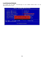
FCC-B Radio Frequency Interference Statement
This equipment has been tested and found to
comply with the limits for a class B digital
device, pursuant to part 15 of the FCC rules.
These limits are designed to provide reasonable protection against harmful interference in a residential
installation. This equipment generates, uses and can radiate radio frequency energy and, if not installed and
used in accordance with the instruction manual, may cause harmful interference to radio communications.
However, there is no guarantee that interference will occur in a particular installation. If this equipment does
cause harmful interference to radio or television reception, which can be determined by turning the equipment
off and on, the user is encouraged to try to correct the interference by one or more of the measures listed
below.
4
Reorient or relocate the receiving antenna.
4
Increase the separation between the equipment and receiver.
4
Connect the equipment into an outlet on a circuit different from that to which the receiver is connected.
4
Consult the dealer or an experienced radio/ television technician for help.
Notice 1
The changes or modifications not expressly approved by the party responsible for compliance could void the
user’s authority to operate the equipment.
Notice 2
Shielded interface cables and A.C. power cord, if any, must be used in order to comply with the emission limits.
VOIR LA NOTICE D’NSTALLATION AVANT DE RACCORDER AU RESEAU.
Micro-Star International
MS-7094
This device complies with Part 15 of the FCC Rules. Operation is subject to the following two conditions:
(1) this device may not cause harmful interference, and
(2) this device must accept any interference received, including interference that may cause undesired
operation
G52-M7094X2
i
Copyright Notice
The material in this document is the intellectual property of MICRO-STAR INTERNATIONAL. We take every
care in the preparation of this document, but no guarantee is given as to the correctness of its contents. Our
products are under continual improvement and we reserve the right to make changes without notice.
Trademarks
All trademarks are the properties of their respective owners.
AMD, Athlon™ Athlon™XP, Thoroughbred™ and Duron™ are registered trademarks of AMD Corporation.
Intel® and Pentium® are registered trademarks of Intel Corporation.
PS/2 and OS® 2 are registered trademarks of International Business Machines Corporation.
Microsoft® is a registered trademark of Microsoft Corporation. Windows® 98/2000/NT/XP are registered
trademarks of Microsoft Corporation.
NVIDIA, the NVIDIA logo, DualNet, and nForce are registered trademarks or trademarks of NVIDIA
Corporation in the United States and/or other countries.
Netware® is a registered trademark of Novell, Inc.
Award® is a registered trademark of Phoenix Technologies Ltd.
AMI® is a registered trademark of American Megatrends Inc.
Kensington and MicroSaver are registered trademarks of the Kensington Technology Group.
PCMCIA and CardBus are registered trademarks of the Personal Computer Memory Card International
Association.
Revision History
Revision
Revision History
Date
V1.0
First release for PCB v1.X with VIA K8T800 PRO
®
June 2005
& VT8237R/ VT8237R Plus
V1.1
Update for PCB V1.B with VIA® K8T800 PRO
VT8237R/ VT8237R Plus
ii
July 2005
Safety Instructions
1. Always read the safety instructions carefully.
2. Keep this User Manual for future reference.
3. Keep this equipment away from humidity.
4. Lay this equipment on a reliable flat surface before setting it up.
5. The openings on the enclosure are for air convection hence protects the equipment from overheating.
Do
not cover the openings.
6. Make sure the voltage of the power source and adjust properly 110/220V before connecting the equipment
to the power inlet.
7. Place the power cord such a way that people can not step on it. Do not place anything over the power
cord.
8. Always Unplug the Power Cord before inserting any add-on card or module.
9. All cautions and warnings on the equipment should be noted.
10. Never pour any liquid into the opening that could damage or cause electrical shock.
11. If any of the following situations arises, get the equipment checked by a service personnel:
- The power cord or plug is damaged.
- Liquid has penetrated into the equipment.
- The equipment has been exposed to moisture.
- The equipment does not work well or you can not get it work according to User Manual.
- The equipment has dropped and damaged.
- The equipment has obvious sign of breakage.
12. Do not leave this equipment in an environment unconditioned, storage temperature above 60° C (140°F),
it may damage the equipment.
CAUTION: Danger of explosion if battery is incorrectly replaced. Replace only
with the same or equivalent type recommended by the manufacturer.
iii
WEEE Statement
English
To protect the global environment and as an environmentalist, MSI must remind you that...
Under the European Union ("EU") Directive on Waste Electrical and Electronic Equipment, Directive
2002/96/EC, which takes effect on August 13, 2005, products of "electrical and electronic equipment" cannot
be discarded as municipal waste anymore and manufacturers of covered electronic equipment will be
obligated to take back such products at the end of their useful life. MSI will comply with the product take back
requirements at the end of life of MSI-branded products that are sold into the EU. You can return these
products to local collection points.
Deutsch
Hinweis von MSI zur Erhaltung und Schutz unserer Umwelt
Gemäß der Richtlinie 2002/96/EG über Elektro- und Elektronik-Altgeräte dürfen Elektro- und
Elektronik-Altgeräte nicht mehr als kommunale Abfälle entsorgt werden. MSI hat europaweit verschiedene
Sammel- und Recyclingunternehmen beauftragt, die in die Europäische Union in Verkehr gebrachten Produkte,
am Ende seines Lebenszyklus zurückzunehmen. Bitte entsorgen Sie dieses Produkt zum gegebenen
Zeitpunkt ausschliesslich an einer lokalen Altgerätesammelstelle in Ihrer Nähe.
Français
En tant qu’écologiste et afin de protéger l’environnement, MSI tient à rappeler ceci...
Au sujet de la directive européenne (EU) relative aux déchets des équipement électriques et électroniques,
directive 2002/96/EC, prenant effet le 13 août 2005, que les produits électriques et électroniques ne peuvent
être déposés dans les décharges ou tout simplement mis à la poubelle. Les fabricants de ces équipements
seront obligés de récupérer certains produits en fin de vie. MSI prendra en compte cette exigence relative au
retour des produits en fin de vie au sein de la communauté européenne. Par conséquent vous pouvez
retourner localement ces matériels dans les points de collecte.
Русский
Компания MSI предпринимает активные действия по защите окружающей среды, поэтому напоминаем
вам, что....
В соответствии с директивой Европейского Союза (ЕС) по предотвращению загрязнения окружающей
среды использованным электрическим и электронным оборудованием (директива WEEE 2002/96/EC),
вступающей в силу 13 августа 2005 года, изделия, относящиеся к электрическому и электронному
оборудованию, не могут рассматриваться как бытовой мусор, поэтому производители
вышеперечисленного электронного оборудования обязаны принимать его для переработки по
окончании срока службы. MSI обязуется соблюдать требования по приему продукции, проданной под
маркой MSI на территории EC, в переработку по окончании срока службы. Вы можете вернуть эти
изделия в специализированные пункты приема.
Español
MSI como empresa comprometida con la protección del medio ambiente, recomienda:
Bajo la directiva 2002/96/EC de la Unión Europea en materia de desechos y/o equipos electrónicos, con fecha
de rigor desde el 13 de agosto de 2005, los productos clasificados como "eléctricos y equipos electrónicos" no
pueden ser depositados en los contenedores habituales de su municipio, los fabricantes de equipos
electrónicos, están obligados a hacerse cargo de dichos productos al termino de su período de vida. MSI
estará comprometido con los términos de recogida de sus productos vendidos en la Unión Europea al final de
su periodo de vida. Usted debe depositar estos productos en el punto limpio establecido por el ayuntamiento
de su localidad o entregar a una empresa autorizada para la recogida de estos residuos.
Nederlands
Om het milieu te beschermen, wil MSI u eraan herinneren dat….
De richtlijn van de Europese Unie (EU) met betrekking tot Vervuiling van Electrische en Electronische
producten (2002/96/EC), die op 13 Augustus 2005 in zal gaan kunnen niet meer beschouwd worden als
vervuiling.
Fabrikanten van dit soort producten worden verplicht om producten retour te nemen aan het eind van hun
levenscyclus. MSI zal overeenkomstig de richtlijn handelen voor de producten die de merknaam MSI dragen
en verkocht zijn in de EU. Deze goederen kunnen geretourneerd worden op lokale inzamelingspunten.
iv
Srpski
Da bi zaštitili prirodnu sredinu, i kao preduzeće koje vodi računa o okolini i prirodnoj sredini, MSI mora da vas
podesti da…
Po Direktivi Evropske unije ("EU") o odbačenoj ekektronskoj i električnoj opremi, Direktiva 2002/96/EC, koja
stupa na snagu od 13. Avgusta 2005, proizvodi koji spadaju pod "elektronsku i električnu opremu" ne mogu
više biti odbačeni kao običan otpad i proizvođači ove opreme biće prinuđeni da uzmu natrag ove proizvode na
kraju njihovog uobičajenog veka trajanja. MSI će poštovati zahtev o preuzimanju ovakvih proizvoda kojima je
istekao vek trajanja, koji imaju MSI oznaku i koji su prodati u EU. Ove proizvode možete vratiti na lokalnim
mestima za prikupljanje.
Polski
Aby chronić nasze środowisko naturalne oraz jako firma dbająca o ekologię, MSI przypomina, że...
Zgodnie z Dyrektywą Unii Europejskiej ("UE") dotyczącą odpadów produktów elektrycznych i elektronicznych
(Dyrektywa 2002/96/EC), która wchodzi w życie 13 sierpnia 2005, tzw. “produkty oraz wyposażenie
elektryczne i elektroniczne " nie mogą być traktowane jako śmieci komunalne, tak więc producenci tych
produktów będą zobowiązani do odbierania ich w momencie gdy produkt jest wycofywany z użycia. MSI
wypełni wymagania UE, przyjmując produkty (sprzedawane na terenie Unii Europejskiej) wycofywane z użycia.
Produkty MSI będzie można zwracać w wyznaczonych punktach zbiorczych.
TÜRKÇE
Çevreci özelliğiyle bilinen MSI dünyada çevreyi korumak için hatırlatır:
Avrupa Birliği (AB) Kararnamesi Elektrik ve Elektronik Malzeme Atığı, 2002/96/EC Kararnamesi altında 13
Ağustos 2005 tarihinden itibaren geçerli olmak üzere, elektrikli ve elektronik malzemeler diğer atıklar gibi çöpe
atılamayacak ve bu elektonik cihazların üreticileri, cihazların kullanım süreleri bittikten sonra ürünleri geri
toplamakla yükümlü olacaktır. Avrupa Birliği’ne satılan MSI markalı ürünlerin kullanım süreleri bittiğinde MSI
ürünlerin geri alınması isteği ile işbirliği içerisinde olacaktır. Ürünlerinizi yerel toplama noktalarına
bırakabilirsiniz.
ČESKY
Záleží nám na ochraně životního prostředí - společnost MSI upozorňuje...
Podle směrnice Evropské unie ("EU") o likvidaci elektrických a elektronických výrobků 2002/96/EC platné od
13. srpna 2005 je zakázáno likvidovat "elektrické a elektronické výrobky" v běžném komunálním odpadu a
výrobci elektronických výrobků, na které se tato směrnice vztahuje, budou povinni odebírat takové výrobky
zpět po skončení jejich životnosti. Společnost MSI splní požadavky na odebírání výrobků značky MSI,
prodávaných v zemích EU, po skončení jejich životnosti. Tyto výrobky můžete odevzdat v místních sběrnách.
MAGYAR
Annak érdekében, hogy környezetünket megvédjük, illetve környezetvédőként fellépve az MSI emlékezteti Önt,
hogy ...
Az Európai Unió („EU") 2005. augusztus 13-án hatályba lépő, az elektromos és elektronikus berendezések
hulladékairól szóló 2002/96/EK irányelve szerint az elektromos és elektronikus berendezések többé nem
kezelhetőek lakossági hulladékként, és az ilyen elektronikus berendezések gyártói kötelessé válnak az ilyen
termékek visszavételére azok hasznos élettartama végén.
Az MSI betartja a termékvisszavétellel
kapcsolatos követelményeket az MSI márkanév alatt az EU-n belül értékesített termékek esetében, azok
élettartamának végén. Az ilyen termékeket a legközelebbi gyűjtőhelyre viheti.
Italiano
Per proteggere l’ambiente, MSI, da sempre amica della natura, ti ricorda che….
In base alla Direttiva dell’Unione Europea (EU) sullo Smaltimento dei Materiali Elettrici ed Elettronici, Direttiva
2002/96/EC in vigore dal 13 Agosto 2005, prodotti appartenenti alla categoria dei Materiali Elettrici ed
Elettronici non possono più essere eliminati come rifiuti municipali: i produttori di detti materiali saranno
obbligati a ritirare ogni prodotto alla fine del suo ciclo di vita. MSI si adeguerà a tale Direttiva ritirando tutti i
prodotti marchiati MSI che sono stati venduti all’interno dell’Unione Europea alla fine del loro ciclo di vita. È
possibile portare i prodotti nel più vicino punto di raccolta.
v
Table of Content
English .......................................................................1
Français .....................................................................13
Deutsch ......................................................................25
简体中文......................................................................39
繁體中文......................................................................51
日本語 .........................................................................63
vi
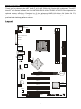
Introduction
Thank you for choosing the K8T Neo2-F v2.0 (MS-7094 v1.X) Series ATX mainboard. The K8T
®
®
Neo2-F v2.0 Series is based on VIA K8T800 PRO & VIA VT823R/ VT8237R Plus chipsets for
optimal system efficiency. Designed to fit the advanced AMD K8 Athlon 64/ Athlon 64 FX
processors in Socket939 package, the K8T Neo2-F v2.0 Series delivers a high performance and
professional desktop platform solution.
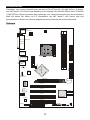
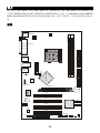
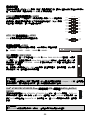
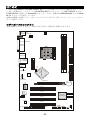
Layout
CFAN1
JPW 1
DIMM1
DIMM2
Top : mouse
B ottom: keyboard
Top : Parallel Port
IDE 1
Bottom:
COM1
JCA SE1
LAN
Chip
IDE 2
SFAN1
T: Line-In
M: Line-Out
B: Mic
VIA
K8T800 P RO
T: LA N jack
B : USB ports
JWR1
USB ports
JCOM2
(optional)
BIOS
Winbond
W 83627THF
AGP Slot
BATT
+
PCI1
P CI2
VT8237R/
VT8237R Plus
JCD1
SATA2
P CI3
SATA1
Codec
P CI4
JAUD1
JUS B1 JUSB2
FDD1
JFP1
1
JBAT1 JFP2
Specifications
CPU
®
l
Supports AMD K8 Athlon 64/ Athlon 64 FX-55 processors in socket 939 package.
l
Supports up to Athlon 64 4000+/ Athlon 64 FX-55 processor or higher speed.
l
For the latest information about CPU, please visit
http://www.msi.com.tw/program/products/mainboard/mbd/pro_mbd_cpu_support.php
Chipset
l
VIA K8T800 PRO chipset
- Hyper Transport
TM
connection to AMD K8 Athlon 64/ Athlon 64 FX processor
- 8 or 16 bit control/ address/ data transfer both directions
- 1000/ 800 MHz “Double Data Rate” operation both direction.
- AGP v3.0 compliant with 8X transfer mode.
l
VIA VT8237R/ VT8237R Plus chipset
- Supports dual channel native SATA controller up to 150MB/s with RAID 0 or RAID 1.
- Supports USB2.0 up to 8 ports.
- Integrated AC97 audio.
- 2 channel Ultra ATA 66/100/133 bus Master IDE controller.
- PCI Master v2.3, I/O APIC.
- Supports both ACPI and legacy APM power management.
Main Memory
l
Supports two unbuffered/non-ECC DIMM of 2.5 Volt DDR400/ 333/ 266 SDRAM.
l
Supports up to 2GB memory size DDR memory.
l
Supports dual channel DDR.
(For the updated supporting memory modules, please visit
http://www.msi.com.tw/program/products/mainboard/mbd/pro_mbd_trp_list.php )
Slots
l
One AGP (Accelerated Graphics Port) slot compliant with AGP 3.0 spec.
l
Four PCI 2.3 32-bit PCI Bus slots, includes one orange slot which is reserved as a
communication slot.
On-Board IDE
l
Two Ultra DMA 66/100/133 IDE controller integrated in VT8237R/ VT8237R Plus.
- Supports PIO, Bus Master operation modes.
- Can connect up to four Ultra ATA drives.
l
Serial ATA/150 controller integrated in VT8237R/ VT8237R Plus
- Up to 150MB/sec transfer rate.
- Can connect up to two Serial ATA drives.
2
On-Board Peripherals
l
On-Board Peripherals includes:
- 1 floppy port supports 1 FDDs with 360K, 720K, 1.2M, 1.44M and 2.88Mbytes.
- 2 serial ports (Rear * 1/ Front * 1) and 1 parallel port supports SPP/EPP/ECP mode.
- 8 USB 2.0 ports (Rear * 4/ Front * 4).
- 3 audio (Line-In/Line-Out/Mic) ports.
- 1 RJ-45 LAN Jack.
Audio
®
l
AC97 link controller integrated in VIA VT8237R/ VT8237R Plus chipset.
l
6-channel audio codec Realtek ALC655.
- Compliance with AC97 v2.3 Spec.
- Meet PC2001 audio performance requirement.
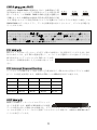
LAN
l
Realtek 8110S (default) or 8100C (optional)
- Supports 10Mb/s and 100Mb/s, (1000Mb/s => for 8110S only).
- Supports ACPI Power Management.
BIOS
l
The mainboard BIOS provides “Plug & Play” BIOS which detects the peripheral devices and
expansion cards of the board automatically.
l
The mainboard provides a Desktop Management Interface (DMI) function that records your
mainboard specifications.
Dimension
l
ATX Form Factor: 30.5 cm x 19.4 cm.
Mounting
l
6 mounting holes.
Others
l Supports PS/2 Keyboard/Mouse.
l Hardware monitor can monitor CPU’s temperature/voltage.
3
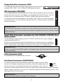
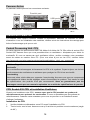
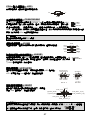
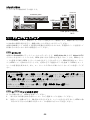
Rear Panel
The rear panel provides the following connectors:
Line ln
Mouse
Parallel port
LAN
USB ports
Keyboard COM port
USB ports Line Out
MIC
Hardware Setup
This chapter tells you how to install the CPU, memory modules, and expansion cards, as well as
how to setup the jumpers on the mainboard. It also provides the instructions on connecting the
peripheral devices, such as the mouse, keyboard, etc. While doing the installation, be careful in
holding the components and follow the installation procedures.
Central Processing Unit: CPU
®
The mainboard supports AMD K8 Athlon 64/ Athlon 64 FX processors. The mainboard uses a
CPU socket called Socket-939. When you are installing the CPU, make sure to install the cooler
to prevent overheating. If you do not have the CPU cooler, contact your dealer to purchase and
install them before turning on the computer.
For the latest information about CPU, please visit
http://www.msi.com.tw/program/products/mainboard/mbd/pro_mbd_cpu_support.php.
MSI Reminds You...
Overheating
Overheating will seriously damage the CPU and system, always make sure the cooling fan can
work properly to protect the CPU from overheating.
Overclocking
This motherboard is designed to support overclocking. However, please make sure your
components are able to tolerate such abnormal setting, while doing overclocking. Any attempt to
operate beyond product specifications is not recommended. We do not guarantee the damages
or risks caused by inadequate operation or beyond product specifications.
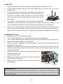
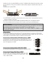
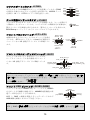
Socket-939 CPU and Cooler Installation
When you are installing the CPU, make sure the CPU has a cooler attached on the top to prevent
overheating. If you do not have the cooler, contact your dealer to purchase and install them
before turning on the computer. Meanwhile, do not forget to apply some silicon heat transfer
compound on CPU before installing the cooler for better heat dispersion.
Follow the steps below to install the CPU & cooler correctly. Wrong installation will cause the
damage of your CPU & mainboard.
4
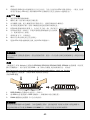
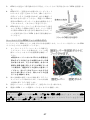
Install CPU
1.
Please turn off the power and unplug the power cord before installing the CPU.
2.
Pull the lever sideways away from the socket. Make sure to raise the lever up to a 90
degree angle.
3.
Look for the gold arrow on the CPU. And there is a triangle mark
located on the corner of the CPU socket. The CPU can only fit in
the correct orientation. Match the gold arrow with the triangle
Gold arrow
mark and lower the CPU down onto the socket (refer to the
picture right).
4.
If the CPU is correctly installed, the pins should be completely
Triangle mark
embedded in to the socket and can not be seen. Please note that any violation of the
correct installation procedures may cause permanent damages to your mainboard.
5.
Press the CPU down firmly into the socket and close the lever. As the CPU is likely to move
while the lever is being closed, always close the lever with your fingers pressing tightly on
top of the CPU to make sure the CPU is properly and completely embedded into the socket.
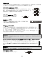
Installing CPU Cooler
1.
Detach the shield of the backplate’s paster.
2.
Turn over the mainboard, and install the backplate to the proper position.
3.
Turn over the mainboard again, and place the mainboard on the flat surface. Locate the two
screw holes of the backplate on the mainboard.
4.
Align the retention mechanism and the backplate. Fix the retention mechanism and the
backplate with two screws.
5.
Position the cooling set onto the retention mechanism. Hook one end of the clip to hook first,
and then press down the other end of the clip to fasten the cooling set on the top of the
retention mechanism.
6.
Locate the Fix Lever, Safety Hook and Fixed Bolt. Lift up
the intensive fixed lever.
Safety Hook
7.
Fasten down the lever.
8.
Make sure the safety hook completely clasps the fixed bolt
of the retention mechanism.
9.
Attach the CPU Fan cable to the CPU fan connector on
the mainboard.
Fixed Lever
Fixed Bolt
MSI Reminds You...
While disconnecting the Safety Hook from the fixed bolt, it is necessary to keep an eye on your
fingers, because once the Safety Hook is disconnected from the fixed bolt, the fixed lever will
spring back instantly.
5
Memory
The mainboard provides two 184-pin unbuffered DDR266/ DDR333/ DDR400 DDR SDRAM, and
supports the memory size up to 2GB. To operate properly, at least one DIMM module must be
installed. (For the updated supporting memory modules, please visit
http://www.msi.com.tw/program/products/mainboard/mbd/pro_mbd_trp_list.php)
Install at least one DIMM module on the slots. Memory modules can be installed on the slots in
any order. You can install either single- or double-sided modules to meet your own needs.
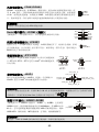
Installing DDR Modules
Volt
1.
Notch
The DDR DIMM has only one notch on the center of module. The module will only fit in the
right orientation.
2.
Insert the DIMM memory module vertically into the DIMM slot. Then push it in until the
golden finger on the memory module is deeply inserted in the socket.
3.
The plastic clip at each side of the DIMM slot will automatically close.
MSI Reminds You...
Always insert the memory modules into the GREEN slot first and it is strongly recommended not
to insert the PURPLE slot while the GREEN slot is left empty.
Please select the identical memory to install on the DIMM1 and DIMM2, or it may cause some
unknown failure.
Power Supply
The mainboard supports ATX power supply for the power system. Before inserting the power
supply connector, always make sure that all components are installed properly to ensure that no
damage will be caused. A 350W or above power supply is suggested.
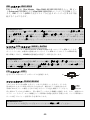
ATX 20-Pin Power Connector: JWR1
This connect allows you to connect to an ATX power supply. To
connect to the ATX power supply, make sure the plug of the power
supply is inserted in the proper orientation and pins are aligned. Then
push down the power supply firmly into the connector.
10 20
+12 V
+5V
5VSB
+5V
PWR OK
-5V
GND
GND
+5V
GND
GND
GND
+5V
PS-ON#
GND
GND
+3. 3V
- 12V
+3. 3V
+3.3V
1
ATX 12V Power Connector: JPW1
11
1 3
This 12V power connector is used to provide power to the CPU.
GND
12V
GND
12V
2 4
6
Floppy Disk Drive Connector: FDD1
The mainboard provides a standard floppy disk drive connector that
supports 360K, 720K, 1.2M, 1.44M and 2.88M floppy disk types.
IDE Connectors: IDE1/IDE2
The mainboard has two 32-bit Enhanced PCI IDE and Ultra DMA 66/100/133 controller
that provides PIO mode 0~4, Bus Master, and Ultra DMA 66/100/133 function. You can
connect up to four hard disk drives, CD-ROM, 120MB Floppy and other devices.
The first hard drive should always be connected to IDE1. IDE1 can connect a Master
and a Slave drive. You must configure second hard drive to Slave mode by setting the
jumper accordingly.
MSI Reminds You...
If you install two hard disks on cable, you must configure the second drive to Slave mode by
setting its jumper. Refer to the hard disk documentation supplied by hard disk vendors for jumper
setting instructions.
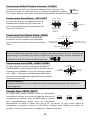
Serial ATA Connectors controlled by VIA VT8237R/ VT8237R Plus:
SATA1/ SATA2
®
The Southbridge of this mainboard is VIA VT8237R/ VT8237R Plus, which supports 2
serial connectors SATA1~2.
7
SATA1~2 are dual high-speed Serial ATA interface ports. Each supports 1st generation
serial ATA data rates of 150 MB/s. All SATA connectors are fully compliant with Serial
1
ATA 1.0 specifications. Each Serial ATA connector can connect to 1 hard disk device.
MSI Reminds You...
Please do not fold the serial ATA cable in a 90-degree angle, which will cause the loss of data
during transmission.
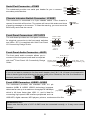
CD-In Connector: JCD1
The connector is for CD-ROM audio connector.
R
L
GND
Fan Power Connectors: CFAN1/SFAN1
The CFAN1 (processor fan) and SFAN1 (system fan) support system cooling
fan with +12V. When connecting the wire to the connectors, always take note
that the red wire is the positive and should be connected to the +12V, the
GND
+12V
Sensor
black wire is Ground and should be connected to GND. If the mainboard has a System Hardware
Monitor chipset on-board, you must use a specially designed fan with speed sensor to take
advantage of the CPU fan control.
MSI Reminds You...
Always consult the vendors for proper CPU cooling fan.
7
10 9
Serial Port Connector: JCOM2
The mainboard provides one serial port header for you to connect
secondary serial devices.
KEY
CTS
DSR
DTR
SIN
RI
RTS
GND
SOUT
2 1
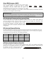
Chassis intrusion Switch Connector: JCASE1
This connector is connected to a 2-pin chassis switch. If the chassis is
GND
CINTRU
2
1
opened, the switch will be short. The system will record this status and show
a warning message on the screen. To clear the warning, you must enter the
BIOS utility and clear the record.
Front Panel Connectors: JFP1/JFP2
Reset HDD
Switch LED
The mainboard provides two front panel connectors
for electrical connection to the front panel switches
and LEDs. JFP1 is compliant with Intel Front Panel
I/O Connectivity Design Guide.
9
10
1
2
12
Power
LED
Speaker
Power Power
Switch LED
78
JFP2
JFP1
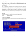
Front Panel Audio Connector: JAUD1
The front panel audio connector allows you to
AUD_RET_R
AUD_VCC
connect to the front panel audio and is compliant
®
with Intel Front Panel I/O Connectivity Design
Guide.
Key
AUD_RET_L(10)
AUD_FPOUT_L(9)
(2)AUD_GND
(1)AUD_MIC
AUD_MIC_BIAS HP_ON
AUD_FPOUT_R
MSI Reminds You...
If you do not want to connect to the front audio header, pins 5 & 6, 9 & 10 have to be jumpered in
order to have signal output directed to the rear audio ports. Otherwise, the Line-Out connector on
the back panel will not function.
2
1
10
9
Front USB Connector: JUSB1/ JUSB2
The mainboard provides two standard USB 2.0 pin
USB0+
USB0-
GND
headers JUSB1 & JUSB2. USB2.0 technology increases
data transfer rate up to a maximum throughput of 480Mbps,
(9)Key
(10)USB0C
which is 40 times faster than USB 1.1, and is ideal for
connecting high-speed USB interface peripherals such as
VCC(1)
VCC(2)
GND USB1USB1+
USB HDD, digital cameras, MP3 players, printers, modems and the like.
MSI Reminds You...
Please note that the pins of VCC & GND must be connected correctly, or it may cause some
damage.
8
Clear CMOS Jumper: JBAT1
There is a CMOS RAM on board that has a power supply
from external battery to keep the data of system
configuration. With the CMOS RAM, the system can
3 2 1
3 2 1
3 2 1
Keep Data
Clear Data
automatically boot OS every time it is turned on. If you want
to clear the system configuration, use the JBAT1 (Clear CMOS Jumper) to clear data. Follow the
instructions in the image to clear the data.
MSI Reminds You...
You can clear CMOS by shorting 2-3 pin while the system is off. Then return to 1-2 pin position.
Avoid clearing the CMOS while the system is on; it will damage the mainboard.
PCI (Peripheral Component Interconnect) Slots
The PCI slots allow you to insert the expansion cards to meet your needs. When adding or
removing expansion cards, make sure that you unplug the power supply first. Meanwhile, read
the documentation for the expansion card to make
any necessary hardware or software settings for the
expansion card, such as jumpers, switches or BIOS
configuration.
PCI Interrupt Request Routing
The IRQ, abbreviation of interrupt request line and pronounced I-R-Q, are hardware lines over
which devices can send interrupt signals to the microprocessor. The PCI IRQ pins are typically
connected to the PCI bus INT A# ~ INT D# pins as follows:
Order1
Order2
Order3
Order4
PCI Slot 1
INT A#
INT B#
INT C#
INT D#
PCI Slot 2
INT B#
INT C#
INT D#
INT A#
PCI Slot 3
INT C#
INT D#
INT A#
INT B#
PCI Slot 4
INT D#
INT A#
INT B#
INT C#
AGP (Accelerated Graphics Port) Slot
The AGP slot allows you to insert the AGP graphics card. AGP is an interface specification
designed for the throughput demands of 3D graphics. It introduces a 66 MHz, 32-bit channel for
the graphics controller to directly access main
memory. The slot supports 8X/4X AGP card.
9
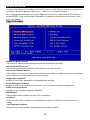
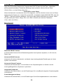
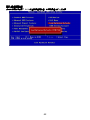
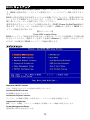
BIOS Setup
Power on the computer and the system will start POST (Power On Self Test) process. When the
message below appears on the screen, press <DEL> key to enter Setup.
Press DEL to enter Setup
If the message disappears before you respond and you still wish to enter Setup, restart the
system by turning it OFF and On or pressing the RESET button. You may also restart the system
by simultaneously pressing <Ctrl>, <Alt>, and <Delete> ke
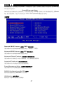
Main Page
Standard CMOS Features
Use this menu for basic system configurations, such as time, date etc.
Advanced BIOS Features
Use this menu to setup the items of Award special enhanced features.
Advanced Chipset Features
Use this menu to change the values in the chipset registers and optimize your system
performance.
Integrated Peripherals
Use this menu to specify your settings for integrated peripherals.
Power Management Setup
Use this menu to specify your settings for power management.
PNP/PCI Configurations
This entry appears if your system supports PnP/PCI.
H/W Monitor
This entry shows your hardware & PC health status.
Cell Menu
Use this menu to specify your settings for frequency/voltage control.
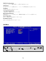
10
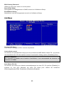
Load Optimized Defaults
Use this menu to load the optimized default settings into the BIOS for the best system
performance operations.
BIOS Setting Password
Use this menu to set the password.
Save & Exit Setup
Save changes to CMOS and exit setup.
Exit Without Saving
Abandon all changes and exit setup.
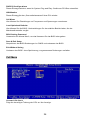
Cell Menu
Current CPU Clock
It shows the current clock of CPU. Read-only.
Cool’n’Quiet control
This feature is especially designed for AMD Athlon/ Athlon FX processor, which provides a CPU
temperature detecting function to prevent your CPU from overheating due to the heavy working
loading. Setting options: [Disabled], [Auto].
MSI Reminds You...
For the purpose of ensuring the stability of Cool'n'Quiet function, it is always recommended to
have the memories plugged in DIMM1.
11
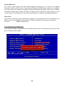
Auto Detect PCI Clk
This item is used to auto detect the PCI slots. When set to [Enabled], the system will remove
(turn off) clocks from empty PCI slots to minimize the electromagnetic interference (EMI).
Settings: [Enabled], [Disabled].
Spread Spectrum
When the motherboard’s clock generator pulses, the extreme values (spikes) of the pulses
creates EMI (Electromagnetic Interference). The Spread Spectrum function reduces the EMI
generated by modulating the pulses so that the spikes of the pulses are reduced to flatter curves.
If you do not have any EMI problem, leave the setting at [Disabled] for optimal system stability
and performance. But if you are plagued by EMI, select the desired range for EMI reduction.
Remember to disable Spread Spectrum function if you are overclocking, because even a slight
jitter can introduce a temporary boost in clock speed which may just cause your overclocked
processor to lock up.
CPU Clock
This item allows you to select the CPU Front Side Bus clock frequency (in MHz) and overclock
the processor by adjusting the FSB clock to a higher frequency. Setting options:
For CPU
FSB200: [200]~[232]
Load Optimized Defaults
You can load the BIOS optimized default values provided by the mainboard manufacturer for the
stable performance.
12
Introduction
Félicitation, vous venez d’acquérir une carte mère ATX K8T Neo2-F v2.0 (MS-7094 v1.X) Series.
®
®
Les K8T Neo2-F v2.0 Series sont basées sur les chipsets VIA K8T800 PRO & VIA VT8237R/
VT8237R Plus offrant un système très performant. Les cartes fonctionnent avec les processeurs
AMD K8 Athlon 64/ Athlon 64 FX (Socket939), les K8T Neo2-F v2.0 Series sont très
performantes et offrent une solution adaptée tant aux professionnels qu’aux particuliers.
Schéma
CFAN1
JPW 1
DIMM1
DIMM2
Top : mouse
B ottom: keyboard
Top : Parallel Port
IDE 1
Bottom:
COM1
JCA SE1
LAN
Chip
IDE 2
SFAN1
T: Line-In
M: Line-Out
B: Mic
VIA
K8T800 P RO
T: LA N jack
B : USB ports
JWR1
USB ports
JCOM2
(optional)
BIOS
Winbond
W 83627THF
AGP Slot
BATT
+
PCI1
P CI2
VT8237R/
VT8237R Plus
JCD1
SATA2
P CI3
SATA1
Codec
P CI4
JAUD1
JUS B1 JUSB2
FDD1
JFP1
13
JBAT1 JFP2
Spécificités
CPU
®
l Supporte les processeurs AMD K8 Athlon 64/ Athlon 64 FX-55 (socket 939).
l Supporte jusqu’à Athlon 64 4000+/ Athlon 64 FX-55 ou plus.
l Pour les dernières mises à jours concernant les CPU, vous pouvez visiter :
http://www.msi.com.tw/program/products/mainboard/mbd/pro_mbd_cpu_support.php
Chipset
l Chipset VIA K8T800 PRO
- Connection Hyper Transport
TM
avec processeur AMD K8 Athlon 64/ Athlon 64 FX
- Contrôle/ adressage/ transfert de données 8 ou 16 bit bidirectionnel
- Opérations bidirectionnelles 1000/ 800 MHz “Double Data Rate”
- AGP v3.0 compatible avec le mode 8X.
l Chipset VIA VT8237R/ VT8237R Plus
- Contrôleur SATA en natif (double canal) jusqu’à 150MB/s avec RAID 0 ou RAID 1.
- Supporte USB2.0 jusqu’à 8 ports.
- AC97 audio intégré.
- 2 contrôleurs IDE bus Master channel Ultra ATA 66/100/133.
- PCI Master v2.3, I/O APIC.
- Supporte à la fois l’ACPI et la gestion de l’alimentation (APM).
Mémoire Principale
l Supporte deux DIMM unbuffered /non-ECC de 2.5 Volt DDR400/ 333/ 266 SDRAM.
l Supporte jusqu’à 2GB de mémoire.
l Supporte la DDR en dual channel.
(Pour connaître les derniers modules de mémoire supportés, vous pouvez visiter :
http://www.msi.com.tw/program/products/mainboard/mbd/pro_mbd_trp_list.php)
Slots
l Un slot AGP (Accelerated Graphics Port) compatible avec les spec. AGP 3.0.
l Quatre slots PCI Bus PCI 2.3 32-bit, comprenant un slot orange réservé au slot de
communication.
IDE Intégré
l Deux contrôleurs IDE Ultra DMA 66/100/133 intégrés dans VT8237R/ VT8237R Plus.
- Supporte les modes opératoires PIO, Bus Master
- Possibilité de connecter jusqu’à quatre disques Ultra ATA.
l Contrôleur intégré Serial ATA/150 dans VT8237R/ VT8237R Plus.
- Taux de transfert jusqu’à 150MB/sec.
- Possibilité de connecter jusqu’à deux disques Serial ATA.
14
Périphériques Intégrés
l Périphériques Intégrés Inclus:
- 1 port floppy supportant 1 FDDs avec 360K, 720K, 1.2M, 1.44M et 2.88Mbytes.
- 2 port de série (Arrière * 1/ Avant * 1) et 1 port parallèle supportant les modes
SPP/EPP/ECP.
- 8 ports USB 2.0 (Arrière * 4/ Avant * 4).
- 3 ports audio (Line-In/Line-Out/Mic).
- 1 RJ-45 LAN Jack.
Audio
®
l Contrôleur AC97 link intégré dans le chipset VIA VT8237R/ VT8237R Plus.
l 6 canaux audio codec Realtek ALC655.
- Compatibles avec les spec. AC97 v2.3.
- Réponds aux exigences audio PC2001.
LAN
l Realtek 8110S (par défaut) ou 8100C (option)
- Supporte le 10Mb/s et le 100Mb/s (1000Mb/s => pour le 8110S uniquement).
- .Supporte l’ACPI Power Management.
BIOS
l La carte procure un BIOS “Plug & Play” qui détecte automatiquement les cartes d’extension
ou les périphériques.
l La carte offre une interface DMI (Desktop Management Interface) qui enregistre les
spécificités de la carte mère.
Dimension
l Format ATX : 30.5 cm x 19.4 cm.
Montage
l 6 trous de montage.
Autres
l Supporte Clavier/Souris PS/2.
l Le « Hardware monitor » permet de surveiller la température/voltage du CPU.
15
Panneau Arrière
Le panneau arrière procure les connecteurs suivants:
Line ln
Mouse
Parallel port
LAN
USB ports
Keyboard COM port
USB ports Line Out
MIC
Installation Matériel
Ce chapitre vous indique comment installer le processeur, barrettes de mémoire et cartes
d’extension. Lors de l’installation des matériels, veuillez suivre les instructions de montage pour
éviter d’endommager quoi que ce soit.
Central Processing Unit: CPU
®
La carte supporte les processeurs AMD K8 Athlon 64/ Athlon 64 FX. Elle utilise le socket CPU
Socket-939. Assurez-vous que vous possédez bien un ventilateur + dissipateur pour éviter la
surchauffe. Si vous ne savez pas quel ventilateur utiliser, veuillez contacter votre revendeur
avant de mettre en marche votre PC. (Pour une mise à jour sur les CPU, veuillez visiter
http://www.msi.com.tw/program/products/mainboard/mbd/pro_mbd_cpu_support.php.
MSI Vous Rappelle...
Surchauffe
Une surchauffe endommagera sérieusement le CPU et le système. Soyez toujours sur du bon
fonctionnement des ventilateurs et radiateurs pour protéger le CPU d’une surchauffe.
Overclocking
Cette carte mère a été créée pour supporter l’overclocking. Assurez vous que vos composants
sont capables de tolérer de tels réglages, avant d’overclocker le système. Tout essais au delà
des spécifications des produits n’est pas recommandé. Nous ne garantissons pas les
dommages causés par une mauvaise opération ou au delà des spécifications du produit.
CPU Socket-939 CPU et installation Ventilateur
Quand vous installerez votre CPU, assurez vous que le CPU possède un système de
refroidissement pour prévenir les surchauffes. Si vous ne possédez pas de système de
refroidissement, contactez votre revendeur pour vous en procurer un et installez le avant
d’allumer l’ordinateur.
Installation du CPU
1.
Veuillez éteindre et débrancher votre PC avant l’installation du CPU
2.
Tirez le levier vers le haut. Assurez-vous qu’il est bien en position ouverte maximum (angle
de 90°)
16
3.
Repérez la flèche dorée. Une marque triangulaire se situe dans
le coin du CPU. Le CPU ne peut être installé que dans un seul
sens. Assemblez la flèche dorée avec la marque dorée et
Gold arrow
abaissez le CPU sur le socket (referez-vous à l’image de droite).
4.
Si le CPU est correctement installé, les broches ne sont plus
visibles. Une mauvaise installation pourrait entraîner des
Triangle mark
dommages sur la carte mère.
5.
Appuyez sur le CPU pendant que vous abaissez le levier. Il faut toujours exercer une
pression sur le CPU pour éviter que ce dernier ne soit pas bien fixé une fois le levier
abaissé.
Installation du ventilateur du CPU
1.
Détachez l’autocollant du bouclier de la plaque arrière.
2.
Retournez la carte mère et installez la plaque arrière dans la bonne position.
3.
Retournez de nouveau la carte mère et placez la sur une surface plane. Localisez les deux
trous de vis de la plaque arrière.
4.
Alignez le mécanisme d’attache et la plaque arrière.
5.
Positionnez le système de refroidissement que le mécanisme d’attache. Accrochez une
extrémité de l’agrafe avant de tout fixer. Appuyez sur les autres extrémités des agrafes pour
accrocher le système de refroidissement sur le dessus du mécanisme d’attache.
6.
Localisez le levier de fixation et accrochez le bien sur son
encoche. Relevez le levier de fixation.
Safety Hook
7.
Fixer le levier vers le bas
8.
Assurez-vous que le crochet de sécurité soit bien attaché
à son encoche sur le mécanisme d’attache.
9.
Attachez le câble du ventilateur du CPU au connecteur du
ventilateur du CPU sur la carte mère.
Fixed Lever
Fixed Bolt
MSI Vous Rappelle...
Lorsque vous détacherez le crochet de sécurité de son encoche, il est nécessaire de garder un
œil sur vos doigts, car une fois le crochet de sécurité détaché le levier de fixation s’ouvrira
instantanément.
Mémoire
La carte mère possède deux slots (184 broches) pour modules de mémoire DDR333 / DDR400
DDR SDRAM, et supporte un maximum de mémoire jusqu’à 2GB. Pour fonctionner
correctement, il faut au moins installer un module de mémoire DIMM. (Pour les dernières mises
à jours de mémoire supportées, merci de visiter
http://www.msi.com.tw/program/products/mainboard/mbd/pro_mbd_trp_list.php)
17
Installer au moins un module DIMM sur les slots. L’installation des modules de mémoires n’a pas
de sens particulier. Vous pouvez installer soit des modules simples ou doubles faces selon vos
besoins.
Installation des modules DDR
Volt
Notch
1. Le DDR DIMM ne possède qu’une encoche en son centre. Ainsi il n’est possible de monter le
module que dans un seul sens.
2. Insérez le module de mémoire DIMM verticalement dans le slot. Puis appuyez dessus
3. Le clip en plastique situé de chaque côté du module va se fermer automatiquement.
MSI Vous Rappelle...
Il faut toujours insérer les modules de mémoire en premier dans le slot VERT et il est fortement
recommandé de ne rien insérer dans le slot VIOLET si le slot VERT est vide.
Merci de sélectionner des mémoires identiques pour installer DIMM1 et DIMM2 ou cela
entraînera des dommages
Alimentation
La carte mère supporte les alimentations ATX. Avant de brancher le connecteur d’alimentation,
Il faut toujours vous assurer que tous les composants sont bien installés afin de ne pas les
endommager. Une alimentation 350W ou supérieur est préconisée.
Connecteur d’alimentation ATX 20 broches: JWR1
Ce connecteur vous permet de connecter l’alimentation ATX. Pour ce
faire assurez-vous que le connecteur est bien positionné dans le bon
sens. Puis appuyer sur le câble.
10 20
+12 V
+5V
5VSB
+5V
PWR OK
-5V
GND
GND
+5V
GND
GND
GND
+5V
PS-ON#
GND
GND
+3. 3V
- 12V
+3. 3V
+3.3V
1
Connecteur d’alimentation ATX 12V: JPW1
Le connecteur d’alimentation 12V est utilisé pour alimenter le CPU
11
1 3
GND
12V
GND
12V
2 4
Connecteur Floppy Disk Drive: FDD1
La carte offre un connecteur standard floppy disk drive
(lecteur de disquette) qui supporte les disques 360K, 720K,
1.2M, 1.44M et 2.88M.
18
Connecteurs IDE: IDE1/IDE2
La carte mère possède un contrôleur 32-bit Enhanced PCI IDE et Ultra DMA
66/100/133 qui procure les fonctions PIO mode 0~4, Bus Master, et Ultra DMA
66/100/133. Vous pouvez connecter jusqu’à 4 matériels (disques durs, CD-ROM,
120MB Floppy).
Le premier disque dur doit être connecté sur l’IDE1. L’IDE1 peut recevoir un matériel
Maître et un Esclave. Vous devez configurer le second disque en mode Esclave et ce à
l’aide du cavalier situé à l’arrière
MSI Vous Rappelle...
Si vous voulez installer deux disques durs, vous devez configurer le second en Esclave en
configurant le cavalier. Se référer à la documentation du disque dur pour les instructions.
Connecteurs Serial ATA contrôlés par VIA VT8237R/ 8237R Plus:
SATA1/SATA2
Le Southbridge de cette carte est VIA
®
VT8237R/ VT8237R Plus, qui supporte 2
connecteurs de série SATA1~2.
7
SATA1~2 sont deux ports d’interface Serial ATA. Chacun supporte la 1e génération de
serial ATA (taux de transfert 150 MB/s). Ces deux connecteurs sont entièrement
1
compatibles avec le Serial ATA 1.0. Chaque connecteur peut être connecté à un disque
dur.
MSI Vous Rappelle...
Ne pas tordre le câble à 90° afin de ne pas l’endommager et éviter les pertes de données lors du
transfert.
Connecteur CD-In : JCD1
Le connecteur est destiné au branchement audio du CD-ROM
R
L
GND
Fan Power Connectors: CFAN1/SFAN1
Le CFAN1 (ventilateur de processeur) et SFAN1 3 broches (system fan)
GND
+12V
NC
supportent le +12V. Lors de la connexion du câble, assurez-vous que le fil
rouge soit connecté au +12V et le fil noir connecté au “GND“. Si la carte mère
possède un système de gestion intégré, vous devez utiliser un ventilateur ayant ces
caractéristiques si vous voulez contrôler le ventilateur du CPU
MSI Vous rappelle...
Il faut toujours consulter votre revendeur au sujet du ventilateur.
Connecteur Port de série: JCOM2 (optionnel)
La carte mère offre un connecteur port de série pour vous permettre
de connecter un second matériel de série.
10 9
KEY
CTS
DSR
DTR
SIN
RI
RTS
GND
SOUT
2 1
19
Connecteur Switch Chassis intrusion: JCASE1
Ce connecteur est relié à un connecteur chassis switch 2 broches. Si le
2
1
Chassis est ouvert, Le switch sera court. Le système enregistrera ce status.
GND
CINTRU
Pour effacer warning, vous devez entrer dans les paramètres du BIOS et effacer le status.
Connecteurs Front Panel : JFP1/JFP2
Reset HDD
Switch LED
La carte mère procure 2 connecteurs pour les
9
10
branchements électriques (LED disque dur…).
JFP1 est compatible avec le Design Intel Front
12
1
2
Power
LED
Speaker
Power Power
Switch LED
Panel I/O Connectivity.
78
JFP2
JFP1
Connecteur Front Panel Audio: JAUD1
AUD_RET_R
Le connecteur audio JAUD1 vous permet de
AUD_VCC
connecter l’audio en façade et est compatible
Key
AUD_RET_L(10)
AUD_FPOUT_L(9)
(2)AUD_GND
(1)AUD_MIC
avec lntel ® Front Panel I/O Connectivity Design
Guide
AUD_MIC_BIAS HP_ON
AUD_FPOUT_R
MSI Vous rappelle...
Si vous ne voulez pas connecter l’audio en façade à l’aide des broches 5 & 6, 9 & 10 doivent être
recouvertes par un cavalier pour envoyer le signal vers les ports audio à l’arrière. Autrement le
connecteur Line-Out à l’arrière ne fonctionnera pas.
2
1
10
9
Connecteurs Front USB: JUSB1/ JUSB2
USB0+
USB0-
La carte mère procure deux connecteurs standard 2.0
JUSB1&JUSB2. La technologie USB 2.0 accroît le taux de
transfert jusqu’à 480Mbps, ce qui est 40 fois plus rapide
GND
(9)Key
(10)USB0C
VCC(1)
VCC(2)
GND USB1USB1+
que l’ USB 1.1. Idéal pour connecter des périphériques
gourmand en bande passante (appareil photo numérique,
caméra numérique etc).
MSI Vous Rappelle...
A noter que les broches VCC et GND doivent être correctement connecter afin d’éviter tout
endommagement.
Cavalier Clear CMOS: JBAT1
La CMOS RAM intégré possède reçoit une alimentation
d’une batterie externe qui permet de garder les données de
3 2 1
configuration du système. Avec la CMOS RAM, le système
peut
automatiquement
booter
avec
les
3 2 1
3 2 1
Keep Data
Clear Data
paramètres
personnalisés du BIOS à chaque fois que le PC est allumé. Si vous voulez effacer la
configuration du système, utilisez le CLR_CMOS1 (Cavalier Clear CMOS) pour effacer les
données. Suivez les instructions de l’image pour effacer les données.
20
MSI Vous Rappelle...
Vous pouvez effacer les données en positionnant le cavalier sur les broches 2-3 quand le PC
n’est pas allumé. Puis il faut remettre le cavalier en position 1-2. Ne surtout pas effacer les
données (Position 2-3) lorsque le PC est en fonction, cela endommagera la carte mère.
Slots PCI (Peripheral Component Interconnect)
Les slots PCI vous permettent la connexion de
cartes d’extension selon vos besoins. Pour installer
ou retirer une carte PCI, il faut que le PC soit éteint. Si la carte PCI nécessite des réglages,
veuillez vous reporter à la documentation fournie avec cette dernière.
PCI Interrupt Request Routing
IRQ est l’abréviation de “interrupt request line”. Les IRQ sont des signaux émis par des matériels.
Les PCI IRQ sont connectés généralement au broches PCI bus INT A# ~ INT D# comme
suivant:
Order1
Order2
Order3
Order4
PCI Slot 1
INT A#
INT B#
INT C#
INT D#
PCI Slot 2
INT B#
INT C#
INT D#
INT A#
PCI Slot 3
INT C#
INT D#
INT A#
INT B#
PCI Slot 4
INT D#
INT A#
INT B#
INT C#
Slot AGP (Accelerated Graphics Port)
Le slot AGR vous permet de connecter une
carte graphique AGP. Cette interface est
particulièrement bien adaptée aux applications
3D. Contrôleur 66MHz, 32-bit avec accès direct à la mémoire principale. Le slot supporte les
cartes AGP 8x/4x.
21
Setup du BIOS
Lorsque le PC démarre le processus de POST (Power On Self Test) se met en route. Quand le
message ci-dessous apparaît, appuyer sur
<DEL> pour accéder au Setup.
Si le message disparaît avant que n’ayez appuyé sur la touche, redémarrez le PC à l’aide du
bouton RESET. Vous pouvez aussi redémarrer en utilisant la combinaison de touches <Ctrl>,
<Alt>, et <Delete>.
Page Principale
Standard CMOS Features
Cette fonction permet le paramétrage des éléments standard du BIOS.
Advanced BIOS Features
Cette fonction permet de paramétrer des éléments avancés du Bios.
Advanced Chipset Features
Cette option vous permet de paramétrer les éléments relatifs au registre du chipset, permettant
ainsi d’optimiser les performances de votre système.
Integrated Peripherals
Utiliser ce menu pour paramétrer les périphériques intégrés.
Power Management Setup
Utilisez ce menu pour appliquer vos choix en ce qui concerne le power management.
PNP/PCI Configurations
Apparaît si votre système supporte PNP/PCI.
H/W Monitor
Cette entrée montre le statut de votre CPU, ventilateur.
Cell Menu
Utiliser ce menu pour configurer vos paramètres de pour le contrôle de la fréquence et du
voltage.
Load Optimzed Defaults
Utiliser ce menu pour charger les paramètres par défaut du BIOS.
22
BIOS Setting Password
Utiliser ce menu pour entrer un mot de passe
Save & Exit Setup
Sauvegarder les changements du CMOS et sortir de l’utilitaire de Setup.
Exit Without Saving
Abandonner tous les changements et sortir de l’utilitaire de Setup.
Cell Menu
Current CPU Clock
Vous montre l’horloge du CPU. Lecture uniquement.
Cool’n’Quiet control
Cet élément est spécialement conçu pour les processeurs AMD Athlon/ Athlon FX, qui procure
une température du CPU de manière à éviter la surchauffe. Setting options: [Disabled], [Auto].
MSI Vous Rappelle...
Afin d’assurer la stabilité de la fonction Cool'n'Quiet, il est recommandé de brancher les
mémoires en DIMM1.
Auto Detect PCI Clk
Cet élément est utilisé pour détecter automatiquement les slots PCI. En position [Enabled], le
système ne veut plus
alimenter les slots PCI libres
éléctromagnétiques (EMI). Paramètres: [Enabled], [Disabled].
23
pour réduire les
émissions
Spread Spectrum
Les cartes mères créent des EMI (Electromagnetic Interference). La fonction de Spread
Spectrum réduit ces EMI. Si vous n’avez pas de problème d’EMI, laisser l’option sur Disabled,
ceci vous permet une stabilité du système et des performances optimales. Dans le cas contraire,
choisissez Enabled pour réduire les EMI. N’oubliez pas de désactiver cette fonction si vous
voulez faire de l’overclocking, afin d’éviter tout problème. Les options : [Disabled], [Enabled].
CPU Clock
Cet élément vous permet de sélectionner la fréquence d’horloge du CPU Front Side Bus (en
MHz), et c’est une possibilité d’overclocker le FDB en indiquant une fréquence supérieure.
For CPU
FSB200: [200]~[232]
Load Optimized Defaults
Vous pouvez charger les paramètres par défaut procurés par le constructeur de la carte mère
pour une performance stable.
24
Einleitung
Danke, dass Sie das K8T Neo2-F v2.0 (MS-7094 v1.X) Series ATX Mainboard gewählt haben.
®
®
Das K8T Neo2-F v2.0 Series Mainboard basiert auf den VIA K8T800 PRO & VIA VT8237R/
VT8237R Plus Chipsätzen und ermöglicht somit ein optimales und effizientes System. Entworfen,
um den hochentwickelten AMD K8 Athlon 64/ Athlon 64 FX Prozessor aufzunehmen, stellt das
K8T Neo2-F v2.0 Series die ideale Lösung zum Aufbau eines professionellen
Hochleistungsdesktopsystems dar.
Layout
CFAN1
JPW 1
DIMM1
DIMM2
Top : mouse
B ottom: keyboard
Top : Parallel Port
IDE 1
Bottom:
COM1
JCA SE1
LAN
Chip
IDE 2
SFAN1
T: Line-In
M: Line-Out
B: Mic
VIA
K8T800 P RO
T: LA N jack
B : USB ports
JWR1
USB ports
JCOM2
(optional)
BIOS
Winbond
W 83627THF
AGP Slot
BATT
+
PCI1
P CI2
VT8237R/
VT8237R Plus
JCD1
SATA2
P CI3
SATA1
Codec
P CI4
JAUD1
JUS B1 JUSB2
FDD1
JFP1
25
JBAT1 JFP2
Spezifikationen
CPU
l
®
Unterstützt AMD K8 Athlon 64/ Athlon 64 FX-55 Prozessoren im Package für den Sockel
939.
l
Unterstützt Prozessoren bis hin zu Athlon 64 4000+/ Athlon 64 FX-55 oder höher.
l
Um die neuesten Informationen zu unterstützten Prozessoren zu erhalten, besuchen Sie
bitte http://www.msi.com.tw/program/products/mainboard/mbd/pro_mbd_cpu_support.php
Chipsatz
l
VIA K8T800 PRO Chipsatz
TM
- HyperTransport
Anbindung an den AMD K8 Athlon 64/ Athlon 64 FX Prozessor
- Bidirektionale Übertragung von Adress-/Steuerinformationen und Daten mit 8 oder 16 Bit
- 1000 MHz/ 800 MHz“Double Data Rate” Betrieb in beiden Richtungen
- erfüllt AGP V3.0 mit 8x Übertragungsmodus.
l
VIA VT8237R/ VT8237R Plus Chipsatz
- Verfügt über einen eingebauten Dual Channel SATA Kontroller mit bis zu 150MB/s und
RAID 0 oder RAID 1.
- Unterstützt USB 2.0 mit bis zu 8 Anschlüssen
- AC97 Audiolösung integriert
- 2- Kanal Ultra Ultra ATA 66/100/133 Bus Master IDE Kontroller
- PCI Master V2.3, Ein-/Ausgabe APIC.
- Unterstützt ACPI und ist rückwärtskompatibel zum APM Stromsparbetrieb.
Hauptspeicher
l
Unterstützt zwei ungepufferte DDR400/ 333/ 266 SDRAM DIMMs mit 2,5 Volt und ohne
ECC.
l
Unterstützt den Speicherausbau auf bis zu 2GB
l
Unterstützt den Zweikanalbetrieb mit DDR.
(Um den letzten Stand bezüglich der unterstützten Speichermodule zu erhalten, besuchen Sie
bitte http://www.msi.com.tw/program/products/mainboard/mbd/pro_mbd_trp_list.php )
Schnittstellen
l
Ein AGP (Accelerated Graphics Port) Slot, der die Spezifikation AGP 3.0 erfüllt.
l
Vier 32-Bit PCI 2.3 Bus Sockel, einschließlich eines orangen, der als Kommunikationssockel
dienen kann.
On-Board IDE
l
Zwei in den VT8237R/ VT8237R Plus integrierte Ultra DMA 66/100/133 IDE Kontroller.
- Unterstützt die Betriebsmodi PIO und Bus Mastering.
- Bis zu vier Ultra ATA Geräte anschließbar.
26
l
In den VT8237R/ VT8237R Plus integrierter Serial ATA/150 Kontroller.
- Übertragungsgeschwindigkeit bis zu 150MB/Sek.
- Bis zu zwei Serial ATA Laufwerke anschließbar.
Peripherieanschlüsse onboard
l
hierzu gehören:
- 1 Anschluss für ein Diskettenlaufwerke mit 360 KB, 720 KB, 1,2 MB, 1,44 MB oder 2,88
MB.
- 2 Serielle Schnittstelle (1 hintere/ 1 vordere) und 1 Parallele Schnittstelle, die die
Betriebsmodi SPP/EPP/ECP unterstützt
- 8 USB 2.0 Anschlüsse (4 hintere/ 4 vordere).
- 1 Satz Audioanschlüsse (Eingang/ Ausgang/ Mikrofon).
- 1 RJ45 LAN Buchse
Audio
®
l
In den VIA VT8237R/ VT8237R Plus Chipsatz integrierter AC97 Anschlusskontroller.
l
6-Kanal Audio Codec Realtek ALC655.
- Erfüllt die Anforderungen der Spezifikationen gemäß AC97 V2.3
- Genügt den Audio- Leistungsanforderungen nach PC2001.
LAN
l
Realtek 8110S (Standard) oder 8100C (Optional)
- Unterstützung von 10/100 Mbit/s, (1000 Mbit/s nur für 8110S)
- Unterstützt ACPI Stromsparfunktionalität.
BIOS
l
Das Mainboard- BIOS verfügt über “Plug & Play”- Funktionalität, mit der angeschlossene
Peripheriegeräte und Erweiterungskarten automatisch erkannt werden.
l
Das Mainboard stellt ein Desktop - Management - Interface (DMI) zur Verfügung, welches
automatisch die Spezifikationen Ihres Mainboards aufzeichnet.
Abmessungen
l
ATX Form Faktor: 30,5 cm x 19,4 cm.
Montage
l
6 Montagebohrungen.
Sonstiges
l Unterstützt PS/2 Tastatur/Maus.
l Verfügt über einen Chipsatz zur Überwachung der Temperatur/Spannung der CPU.
27
Hinteres Anschlusspaneel
Line ln
Parallel port
Mouse
LAN
USB ports
Keyboard COM port
USB ports Line Out
MIC
Das hintere Paneel verfügt über folgende Anschlüsse:
Hardware Setup
Dieses Kapitel informiert Sie darüber, wie Sie die CPU, Speichermodule und Erweiterungskarten
einbauen, des weiteren darüber, wie die Steckbrücken auf dem Mainboard gesetzt werden.
Zudem bietet es Hinweise darauf, wie Sie Peripheriegeräte anschließen, wie z.B. Maus, Tastatur,
usw. Handhaben Sie die Komponenten während des Einbaus vorsichtig und halten Sie sich an
die vorgegebene Vorgehensweise beim Einbau.
Hauptprozessor: CPU
®
Das Mainboard unterstützt AMD K8 Athlon 64/ Athlon 64 FX Prozessoren, es verwendet hierzu
einen CPU Sockel mit der Bezeichnung Sockel 939. Achten Sie beim Einbau bitte darauf, dass
die CPU immer mit einem Kühler versehen sein muss, um Überhitzung zu vermeiden. Verfügen
Sie über keinen Kühler, setzen Sie sich bitte mit Ihrem Händler in Verbindung, um einen solchen
zu erwerben und danach zu installieren, bevor Sie Ihren Computer anschalten.
Um die neuesten Informationen zu unterstützten Prozessoren zu erhalten, besuchen Sie bitte
http://www.msi.com.tw/program/products/mainboard/mbd/pro_mbd_cpu_support.php
MSI weist darauf hin...
Überhitzung
Überhitzung beschädigt die CPU und das System nachhaltig, stellen Sie stets eine korrekte
Funktionsweise des CPU Kühlers sicher, um die CPU vor Überhitzung zu schützen.
Übertakten
Dieses Motherboard wurde so entworfen, dass es Übertakten unterstützt. Stellen Sie jedoch bitte
sicher, dass die betroffenen Komponenten mit den abweichenden Einstellungen während des
Übertaktens
zurecht
kommen.
Von
jedem
Versuch
des
Betriebes
außerhalb
der
Produktspezifikationen kann nur abgeraten werden. Wir übernehmen keinerlei Garantie für die
Schäden und Risiken, die aus unzulässigem oder Betrieb jenseits der Produktspezifikationen
resultieren.
28
Einbau von CPU und Kühler mit dem Sockel-939
Wenn Sie die CPU einbauen, stellen Sie bitte sicher, dass Sie auf der CPU einen Kühler
anbringen, um Überhitzung zu vermeiden. Verfügen Sie über keinen Kühler, setzen Sie sich bitte
mit Ihrem Händler in Verbindung, um einen solchen zu erwerben und danach zu installieren,
bevor Sie Ihren Computer anschalten. Vergessen Sie nicht, etwas Siliziumwärmeleitpaste auf
die CPU aufzutragen, bevor Sie den Prozessorkühler installieren, um eine verbesserte Ableitung
der Hitze zu erzielen.
Folgen Sie den Schritten unten, um die CPU und den Kühler ordnungsgemäß zu installieren. Ein
fehlerhafter Einbau führt zu Schäden an der CPU und dem Mainboard.
Vorgehensweise beim CPU- Einbau
1.
Bitte schalten Sie das System aus und ziehen Sie den Netzstecker, bevor Sie die CPU
einbauen.
2.
Ziehen Sie den Hebel leicht seitlich vom Sockel weg, heben Sie ihn danach bis zu einem
Winkel von ca. 90° an.
3.
Machen Sie den goldenen Pfeil auf der CPU ausfindig. An einer
Ecke des CPU Sockels befindet sich eine Markierung in Form
eines Dreiecks. Die CPU passt nur in der korrekten Ausrichtung.
Goldener
Pfeil
Richten Sie den goldenen Pfeil auf die Dreiecksmarkierung aus
und senken Sie die CPU in den Sockel (Siehe Bild rechts).
Dreieck
4.
Ist die CPU korrekt installiert, sollten die Pins an der Unterseite vollständig versenkt und
nicht mehr sichtbar sein. Beachten Sie bitte, dass jede Abweichung von der richtigen
Vorgehensweise beim Einbau Ihr Mainboard dauerhaft beschädigen kann.
5.
Drücken Sie die CPU fest in den Sockel und drücken Sie den Hebel wieder nach unten bis
in seine Ursprungsstellung. Da die CPU während des Schließens des Hebels dazu neigt,
sich zu bewegen, sichern Sie diese bitte während des Vorgangs durch permanenten
Fingerdruck von oben, um sicherzustellen, dass die CPU richtig und vollständig im Sockel
sitzt.
Installation des CPU Kühlers
1.
Ziehen Sie die Schutzfolie von der Klebstoffschicht der Rückplatte ab.
2.
Drehen Sie das Mainboard um und bringen Sie die Rückplatte an der geeigneten Stelle an.
3.
Drehen Sie das Mainboard wieder auf die Vorderseite und legen Sie es auf einer ebenen
4.
Richten Sie den Rückhaltemechanismus und die Rückplatte auf einander aus.
Fläche ab.
5.
Setzen Sie das Kühlerset auf den Rückhaltemechanismus. Haken Sie zuerst ein Ende des
Haltebügels ein, dann drücken Sie das andere Ende des Bügels herunter, um das
Kühlerset auf dem Rückhaltemechanismus zu befestigen.
29
6.
Machen Sie den Sicherungshebel, den Sicherungshaken und den Sicherungsbolzen
ausfindig. Heben Sie den Sicherungshebel an.
7.
Drücken Sie den Sicherungshebel herab.
8.
Stellen Sie sicher, dass der Sicherungshaken den
Sicherungsbolzen
des
Rückhaltemechanismus
Safety Hook
Sicherungshaken
vollständig umfasst.
9.
Verbinden Sie das Stromkabel des CPU Lüfters mit dem
Anschluss auf dem Mainboard.
Sicherungshebel
Sicherungsbolzen
MSI weist darauf hin...
Es besteht Verletzungsgefahr, wenn Sie den Sicherungshaken vom Sicherungsbolzen trennen.
Sobald der Sicherungshaken gelöst wird, schnellt der Sicherungshaken sofort zurück.
Speicher
Das Mainboard verfügt über zwei Sockel für ungepufferte 184-Pin DDR333 / DDR400 DDR
SDRAM DIMMs und unterstützt den Speicherausbau auf bis zu 2 GB. Um einen
ordnungsgemäßen Betrieb zu ermöglichen, muss mindestens ein DIMM- Speichermodul
eingesetzt sein.
(Um den letzten Stand bezüglich der unterstützten Speichermodule zu erhalten, besuchen Sie
bitte http://www.msi.com.tw/program/products/mainboard/mbd/pro_mbd_trp_list.php)
Setzen Sie mindestens ein Speichermodul in einen Stecksockel. Die Module können in
beliebiger Reihenfolge eingesetzt werden. Gemäß Ihren Anforderungen können Sie entweder
einseitige oder doppelseitige Module verwenden.
Vorgehensweise beim Einbau von DDR Modulen
Volt
1.
Kerbe
DDR DIMMs haben nur eine Kerbe in der Mitte des Moduls. Sie passen nur in einer
Richtung in den Sockel.
2.
Setzen Sie den DIMM- Speicherbaustein senkrecht in den DIMM- Sockel, dann drücken Sie
ihn hinein, bis die goldenen Kontakte tief im Sockel sitzen.
3.
Die Plastikklammern an den Seiten des DIMM- Sockels schließen sich automatisch.
30
MSI weist darauf hin...
Bestücken Sie immer zuerst die GRÜNEN Sockel, zudem ist es in hohem Maße
empfehlenswert, keine Speichermodule in die VIOLETTEN Sockel einzusetzen, solange die
GRÜNEN unbestückt sind.
Bestücken Sie DIMM1 und DIMM2 immer identisch, sonst kann es zu unerwarteten Fehlern
kommen.
Stromversorgung
Das Mainboard unterstützt zur Stromversorgung ATX Netzteile. Bevor Sie den Netzteilstecker
einstecken, stellen Sie stets sicher, dass alle Komponenten ordnungsgemäß eingebaut sind, um
Schäden auszuschließen. Es wird ein Netzteil mit 350W oder mehr empfohlen.
ATX 20-Pin Stromanschluss: JWR1
Hier können Sie ein ATX Netzteil anschließen. Wenn Sie die
Verbindung herstellen, stellen Sie sicher, dass der Stecker in der
korrekten Ausrichtung eingesteckt wird und die Pins ausgerichtet sind.
Drücken Sie dann den Netzteilstecker fest in den Steckersockel.
10 20
+12 V
+5V
5VSB
+5V
PWR OK
-5V
GND
GND
+5V
GND
GND
GND
+5V
PS-ON#
GND
GND
+3. 3V
- 12V
+3. 3V
+3.3V
1
ATX 12V Stromanschluss: JPW1
11
1 3
Dieser 12V Stromanschluss wird verwendet, um die CPU mit Strom zu
GND
12V
GND
versorgen.
12V
2 4
Anschluss des Diskettenlaufwerks: FDD1
Das Mainboard verfügt über einen Standardanschluss für Diskettenlaufwerke mit 360 KB, 720 KB, 1,2 MB, 1,44 MB oder 2,88 MB
Kapazität.
IDE Festplattenanschluss: IDE1/IDE2
Das Mainboard besitzt einen erweiterten 32-Bit PCI IDE und Ultra DMA 66/100/133
Kontroller, der die PIO Modi 0- 4 bereitstellt, Bus Mastering beherrscht und Ultra DMA
66/100/133 Funktionalität bietet. Es können bis zu vier Festplatten, CD-ROM-, 120MB
Disketten-Laufwerke und andere Geräte angeschlossen werden. Die erste Festplatte
sollte immer an IDE1 angeschlossen werden. IDE1 kann ein Master- und ein SlaveLaufwerk verwalten. Das zweite Laufwerk muss durch das entsprechende Setzen einer
Steckbrücke als Slave eingestellt werden.
MSI weist darauf hin...
Verbinden Sie zwei Laufwerke über ein Kabel, müssen Sie das zweite Laufwerk im Slave-Modus
konfigurieren, indem Sie entsprechend den Jumper setzen. Entnehmen Sie bitte die Anweisungen zum Setzen des Jumpers der Dokumentation der Festplatte, die der Festplattenhersteller
zur Verfügung stellt.
31
Serial ATA Anschlüsse gesteuert durch den VIA VT8237R/ VT8237R Plus:
SATA1/SATA2
Bei der Southbridge dieses Mainboards handelt es sich um den VIA
®
VT8237R/
VT8237R Plus, der die zwei Serial ATA Anschlüsse SATA1~2 unterstützt.
7
SATA1~2 sind Zweikanal- Serial ATA Hochgeschwindigkeitsschnittstellen. Jede
unterstützt Serial ATA der 1sten Generation mit einem Datendurchsatz von 150 MB/s.
1
Jeder der Anschlüsse erfüllt vollständig die Serial ATA 1.0 Spezifikationen. An jedem
Serial ATA Anschluss kann eine Festplatte angeschlossen werden
MSI weist darauf hin...
Bitte falten Sie das Serial ATA Kabel nicht in einem Winkel von 90 Grad, da dies zu
Datenverlusten während der Übertragung führt.
CD-Eingang: JCD1
Hier kann das Audiokabel des CD-ROM
Laufwerkes angeschlossen werden.
R
L
GND
Stromanschlüsse für Lüfter: CFAN1/SFAN1
CFAN1 (Prozessorlüfter) und der dreipolige Anschluss SFAN1 (Systemlüfter)
GND
+12V
Sensor
unterstützen aktive Systemlüfter mit + 12V. Wenn Sie den Stecker mit dem
Anschluss verbinden, sollten Sie immer darauf achten, dass der rote Draht
der positive Pol ist und mit +12V verbunden werden sollte, der schwarze Draht ist der Erdkontakt
und sollte mit GND verbunden werden. Ist Ihr Mainboard mit einem Chipsatz zur Überwachung
der Systemhardware und Steuerung der Lüfter versehen, dann brauchen Sie einen speziellen
Lüfter mit Tacho, um diese Funktion zu nutzen.
MSI weist darauf hin...
Bitten Sie stets Ihren Händler bei der Auswahl des geeigneten CPU Kühlers um Hilfe.
10 9
Serieller Anschluss: JCOM2
KEY
CTS
DSR
DTR
SIN
Das Mainboard bietet einen Anschluss für eine Serielle Schnittstelle,
an die zusätzliche serielle Geräte angeschlossen werden können.
RI
RTS
GND
SOUT
2 1
Gehäusekontaktschalter: JCASE1
Dieser Anschluss wird mit einem 2-poligen Gehäusekontaktschalter
verbunden. Wird das Gehäuse geöffnet, wird der Schalter geschlossen.
2
1
GND
CINTRU
Das System zeichnet dies auf. Um die resultierende Warnung zu löschen, müssen Sie das BIOS
aufrufen und dort den Warnzustand zurücksetzen.
Frontpaneel Anschlüsse: JFP1/JFP2
Reset Festplatten
Schalter LED
Das Mainboard verfügt über zwei Anschlüsse für das
Frontpaneel, diese dienen zum Anschluss der Schalter
und
LEDs
des
Frontpaneels.
JFP1
erfüllt
1
2
die
Anforderungen des “Intel Front Panel I/O Connectivity
Design Guide“.
9
10
System System
Schalter LED
JFP1
32
12
System
LED
Lautsprecher
78
JFP2
Audioanschluss des Frontpaneels: JAUD1
Der Audio Vorderanschluss ermöglicht den
AUD_RET_R
AUD_VCC
Anschluss von Audioein- und -ausgängen eines
Frontpaneels. Der Anschluss entspricht den
Richtlinien
des
®
“Intel
Front
Panel
Key
AUD_RET_L(10)
AUD_FPOUT_L(9)
(2)AUD_GND
(1)AUD_MIC
I/O
Connectivity Design Guide”.
AUD_MIC_BIAS HP_ON
AUD_FPOUT_R
MSI weist darauf hin...
Wenn Sie die vorderen Audioanschlüsse nicht verwenden, müssen die Pins 5 & 6 und 9 & 10 mit
sog. „Jumpern“ gebrückt werden, um die Signalausgabe auf die hinteren Audioanschlüsse
umzuleiten. Andernfalls ist der Line -Out Ausgang im hinteren Anschlussfeld ohne Funktion.
2
1
10
9
USB Vorderanschluss: JUSB1/ JUSB2
Das Mainboard verfügt über zwei Standard- USB- 2.0-
USB0+
USB0-
GND
Anschlüsse in Form der Stift- Blöcke JUSB1 und JUSB2.
Die USB 2.0 Technologie erhöht den Datendurchsatz auf
(9)Key
(10)USB0C
maximal 480Mbps, 40 mal schneller als USB 1.1, und ist
bestens
geeignet,
Peripheriegeräte
Hochgeschwindigkeits-
anzuschließen,
wie
z.B.
GND USB1USB1+
USBUSB
VCC(1)
VCC(2)
Festplattenlaufwerke,
Digitalkameras,
MP3-Player, Drucker, Modems und ähnliches.
MSI Reminds You...
Bitte beachten Sie, dass Sie die mit VCC (Stromführende Leitung) und GND (Erdleitung)
bezeichneten Pins korrekt verbinden müssen, ansonsten kann es zu Schäden kommen.
Steckbrücke zur CMOS-Löschung: JBAT1
Auf dem Mainboard gibt es einen sogenannten CMOS
Speicher (RAM), der über eine Batterie gespeist wird und
3 2 1
die Daten der Systemkonfiguration enthält. Er ermöglicht es
dem Betriebssystem, mit jedem Einschalten automatisch
3 2 1
Daten
bewahren
3 2 1
Daten
löschen
hochzufahren. Wollen Sie die Systemkonfiguration löschen,
verwenden Sie hierfür JBAT1 (Clear CMOS Jumper - Steckbrücke zur CMOS Löschung). Halten
Sie sich an die Anweisungen in der Grafik, um die Daten löschen.
MSI weist darauf hin...
Sie können den CMOS löschen, indem Sie die Pins 2-3 verbinden, während das System
ausgeschaltet ist. Kehren Sie danach zur Pinposition 1-2 zurück. Löschen Sie den CMOS nicht,
solange das System angeschaltet ist, dies würde das Mainboard beschädigen.
33
PCI (Peripheral Component Interconnect) Slots
Die PCI Steckplätze ermöglichen Ihnen den Einsatz von PCI- Karten, um das System Ihren
Anforderungen anzupassen. Stellen Sie vor dem Einsetzen oder Entnehmen von Karten sicher,
dass Sie den Netzstecker
jede
gezogen haben. Studieren Sie bitte die Anleitung zur
Erweiterungskarte,
um
Erweiterungskarte
vorzunehmen,
notwendige
sei
Hard
es
-
oder
Softwareeinstellung
für
die
an
Steckbrücken (“Jumpern”), Schaltern oder im BIOS.
PCI Interrupt Request Routing
Die IRQs (Interrupt Request Lines) sind Hardwareverbindungen, über die Geräte
Interruptsignale an den Prozessor senden können. Die PCI IRQ Pins sind typischer Weise in der
folgenden Art mit den PCI Bus Pins INT A# ~ INT D# verbunden:
Reihenfolge1
Reihenfolge2
Reihenfolge3
Reihenfolge4
PCI Slot 1
INT A#
INT B#
INT C#
INT D#
PCI Slot 2
INT B#
INT C#
INT D#
INT A#
PCI Slot 3
INT C#
INT D#
INT A#
INT B#
PCI Slot 4
INT D#
INT A#
INT B#
INT C#
AGP (Accelerated Graphics Port) Slot
Der
AGP
Slot
ermöglicht
den
Einsatz
einer
AGP
Grafikkarte.
AGP
ist
eine
Schnittstellenspezifikation, die gemäß den Anforderungen von 3D Grafiken an den
Datendurchsatz entwickelt wurde. Mit ihr hat die direkte Anbindung des Grafikkontrollers an den
Hauptspeicher
über
einen
mit
66MHz
getakteten 32-Bit Kanal Einzug gehalten. Der
Sockel unterstützt AGP 8x/4x Karten.
34
BIOS Setup
Nach dem Einschalten beginnt der Computer den POST (Power On Self Test – Selbstüberprüfung nach Anschalten). Sobald die Meldung unten erscheint, drücken Sie die Taste
<Entf>(<Del>), um das Setup aufzurufen.
Press DEL to enter Setup
Wenn die Nachricht verschwindet, bevor Sie reagieren, und Sie möchten immer noch ins Setup,
starten Sie das System neu, indem Sie es erst AUS- und danach wieder ANSCHALTEN, oder die
“RESET”-Taste am Gehäuse betätigen. Sie können das System außerdem neu starten, indem
Sie gleichzeitig die Tasten <Strg>,<Alt> und <Entf> drücken (bei manchen Tastaturen
<Ctrl>,<Alt> und <Del>).
Hauptmenü
Standard CMOS Features
In diesem Menü können Sie die Basiskonfiguration Ihres Systems anpassen, so z.B. Uhrzeit,
Datum usw.
Advanced BIOS Features
Verwenden Sie diesen Menüpunkt, um Award -eigne weitergehende Einstellungen an Ihrem
System vorzunehmen.
Advanced Chipset Features
Verwenden Sie dieses Menü, um die Werte in den Chipsatzregistern zu ändern und die
Leistungsfähigkeit Ihres Systems zu optimieren.
Integrated Peripherals
Verwenden Sie dieses Menü, um die Einstellungen für in das Board integrierte Peripheriegeräte
vorzunehmen.
Power Management Setup
Verwenden Sie dieses Menü, um die Einstellungen für die Stromsparfunktionen vorzunehmen.
35
PNP/PCI Configurations
Dieser Eintrag erscheint, wenn Ihr System Plug and Play- Geräte am PCI-Bus unterstützt.
H/W Monitor
Dieser Eintrag gibt den „Gesundheitszustand“ Ihres PCs wieder.
Cell Mean
Hier können Sie Einstellungen zu Frequenzen und Spannungen vornehmen.
Load Optimized Defaults
Hier können Sie die BIOS- Voreinstellungen für den stabilen Betrieb laden, die der
Mainboardhersteller vorgibt.
BIOS Setting Password
Verwenden Sie dieses Menü, um das Kennwort für das BIOS einzugeben.
Save & Exit Setup
Abspeichern der BIOS-Änderungen im CMOS und verlassen des BIOS.
Exit Without Saving
Verlassen des BIOS´ ohne Speicherung, vorgenommene Änderungen verfallen.
Cell Menu
Current CPU Clock
Zeigt die derzeitigen Taktung der CPU an. Nur Anzeige.
36
Cool’n’Quiet control
Diese Funktion wurde speziell für AMD Athlon/ Athlon FX Prozessoren entworfen und stellt eine
Funktion zur Erfassung der CPU Temperatur bereit, um Ihre CPU vor Überhitzung durch hohe
Last zu bewahren. Mögliche Einstellungen: [Disabled](ausgeschaltet), [Auto].
MSI weist darauf hin...
Um die Stabilität der Cool'n'Quiet Funktion sicher zu stellen, wird es stets empfohlen, DIMM1 mit
Speicherbausteinen zu bestücken.
Auto Detect PCI Clk
Hier wird automatisch festgestellt, welche PCI- Sockel belegt sind. Lautet die Einstellung auf
[Enabled] (eingeschaltet), deaktiviert das System die Taktung leerer PCI- Sockel, um die
Elektromagnetische
Störstrahlung
zu
minimieren.
Mögliche
Einstellungen:
[Enabled]
(eingeschaltet) oder [Disabled] (ausgeschaltet).
Spread Spectrum
Pulsiert der Taktgenerator des Motherboards, erzeugen die Extremwerte (Spitzen) der Pulse EMI
(Elektromagnetische Interferenzen). Die Spread Spectrum Funktion reduziert die erzeugten EMI,
indem die Pulse so moduliert werden, das die Pulsspitzen zu flacheren Kurven reduziert werden.
Sollten Sie keine Probleme mit Interferenzen haben, belassen Sie es bei der Einstellung
[Disabled] (ausgeschaltet), um bestmögliche Systemstabilität und -leistung zu gewährleisten.
Stellt für sie EMI ein Problem dar, wählen Sie die gewünschte Bandbreite zur Reduktion der EMI.
Denken Sie daran Spread Spectrum zu deaktivieren, wenn Sie übertakten, da sogar eine leichte
Schwankung eine vorübergehende Taktsteigerung erzeugen kann, die gerade ausreichen mag,
um Ihren übertakteten Prozessor zum einfrieren zu bringen.
CPU Clock
Hier können Sie die Frequenz des externen CPU Taktes (CPU Front Side Bus) wählen (in MHz)
und durch Höhersetzen der Frequenz des FSB den Prozessor übertakten. Mögliche
Einstellungen: Für CPU FSB200: [200]~[232]
37
Load Optimized Defaults
Hier können Sie die BIOS- Voreinstellungen für den stabilen Betrieb laden, die der
Mainboardhersteller vorgibt.
38
简介
感谢您购买 K8T Neo2-F v2.0(MS-7094 v1.X)Series ATX 主板。K8T Neo2-F v2.0 Series 是基
®
®
于 VIA K8T800 PRO & VIA VT8237R/ VT8237R Plus 芯片组,为 Socket939 封装的 AMD K8
Athlon 64/ Athlon 64 FX 处理器量身定做的高性能主板,提供了高性能、专业化的桌面平台解决方
案。
布局
CFAN1
JPW 1
DIMM1
DIMM2
Top : mouse
B ottom: keyboard
Top : Parallel Port
IDE 1
Bottom:
COM1
JCA SE1
LAN
Chip
IDE 2
SFAN1
T: Line-In
M: Line-Out
B: Mic
VIA
K8T800 P RO
T: LA N jack
B : USB ports
JWR1
USB ports
JCOM2
(optional)
BIOS
Winbond
W 83627THF
AGP Slot
BATT
+
PCI1
P CI2
VT8237R/
VT8237R Plus
JCD1
SATA2
P CI3
SATA1
Codec
P CI4
JAUD1
JUS B1 JUSB2
FDD1
JFP1
39
JBAT1 JFP2
规格
CPU
®
l 支持 socket 939 封装的 AMD K8 Athlon 64/ Athlon 64 FX-55 处理器
l 支持 Athlon 64 4000+/ Athlon 64 FX-55 处理器或更高频率
l 要了解关于 CPU 的最新信息,请访问
http://www.msi.com.tw/program/products/mainboard/mbd/pro_mbd_cpu_support.php
芯片组
l VIA K8T800 PRO 芯片组
- Hyper Transport
TM
连接到 AMD K8 Athlon 64/ Athlon 64 FX 处理器
- 8 或 16 bit 控制/地址/数据双向传输
- 1000/ 800 MHz“双倍数据速率”双向工作模式
- AGP v3.0 兼容 8X 传输模式
l VIA VT8237R/ VT8237R Plus 芯片组
- 支持 2 条信道本地 SATA 控制器,速度可高达 150MB/s,支持 RAID 0 或 RAID 1
- 支持 USB2.0,多达 8 个端口
- 集成了 AC97 音频
- 2 通道 Ultra ATA 66/100/133 总线 Master IDE 控制器
- PCI Master v2.3,I/O APIC.
- 支持 ACPI 和传统 APM 电源管理
主内存
l 支持 2 条无缓冲/无 ECC 的 2.5V DDR400/ 333/ 266 SDRAM DIMM
l 最高支持 2GB 的 DDR 容量
l 支持双通道 DDR
(要了解内存模组支持的更新详情,请访问
http://www.msi.com.tw/program/products/mainboard/mbd/pro_mbd_trp_list.php )
插槽
l 1 条 AGP (加速图形端口)插槽,兼容 AGP 3.0 规格
l 4 条 PCI 2.3 32-bit PCI 总线插槽,包含作为通讯插槽的橙色插槽
板载 IDE
l 2 条 Ultra DMA 66/100/133 IDE 控制器,集成于 VT8237R/ VT8237R Plus 中
- 支持 PIO、Bus Master 工作模式
- 最多可连接 4 台 Ultra ATA 设备
l Serial ATA/150 控制器集成于 VT8237R/ VT8237R Plus 中
- 传输速度可高达 150MB/sec
- 最多可连接 2 台 Serial ATA 设备
40
板载周边
l 板载周边包括:
- 1 个软驱接口,支持 1 台 360K, 720K, 1.2M, 1.44M 和 2.88 Mbytes 的软驱
- 2 个串行端口(后置* 1/ 前置* 1),1 个支持 SPP/EPP/ECP 的并行端口
- 8 个 USB 2.0 端口(后置* 4/ 前置* 4)
- 3 个音频(Line-In/Line-Out/Mic)端口
- 1 个 RJ-45 LAN 插孔
音频
®
l AC97 连接控制器,集成于 VIA VT8237R/ VT8237R Plus 芯片组中
l 6-声道音频编解码 Realtek ALC655
- 符合 AC97 v2.3 规格
- 满足 PC2001 音频性能要求
LAN
l Realtek 8110S(缺省)或 8100C(选配)
- 支持 10Mb/s 和 100Mb/s(1000Mb/s=>仅对于 8110S)
- 支持 ACPI 电源管理
BIOS
l 主板的 BIOS 提供“Plug & Play”(即插即用)功能,能够自动侦测周边设备和连接于主板上
的扩展卡
l 主板提供了桌面管理界面(DMI)功能,可记录您主板的规格
规格
l ATX 规格结构:30.5 cm x 19.4 cm
固定孔
l 6 个固定孔
其他
l 支持 PS/2 键盘/鼠标
l 硬件监视,监视 CPU 温度/电压
41
后置面板
后置面板提供了以下接口:
Line ln
Mouse
Parallel port
LAN
USB ports
Keyboard COM port
USB ports Line Out
MIC
硬件安装
这一章主要告诉您如何安装 CPU、内存、扩展卡,也会告诉您怎样设置主板上的跳线,并提供连
接外围设备的指导,如鼠标,键盘等。安装时,请谨慎拿各零部件并且按照安装说明的步骤进行。
中央处理器:CPU
®
本主板支持 Socket-939 的 AMD K8 Athlon 64/ Athlon 64 FX 处理器。当您在安装 CPU 时,请务
必确认您使用的 CPU 带有防过热的散热片和降温风扇。如果您的 CPU 没有散热片和降温风扇,
请与销售商联系,购买或索取以上设备,并在开机之前妥善安装。
要了解关于 CPU 的最新信息,请访问
http://www.msi.com.tw/program/products/mainboard/mbd/pro_mbd_cpu_support.php
微星提醒您...
温度过高
温度过高会严重损害 CPU 和系统,请务必确认所使用的降温风扇始终能够正常工作,保护 CPU
以免过热烧毁。
超频
本主板设计可支持超频运行。但在进行超频前,请先确认您计算机的相关部件能够支持此非正常的
设定。我们不推荐您在标准以外的规格运行此设备。对于任何非正常的设定或在标准以外规格运行
本设备所造成的损失,我们不予担保。
Socket-939 CPU 和风扇的安装
当您在安装 CPU,请确认 CPU 带有散热片和风扇放置在 CPU 顶部,以防止 CPU 过热。如果您
没有散热片和风扇,请联系经销商以购买和安装。
请根据以下步骤来正确安装 CPU 和风扇。错误的安装可能会损坏您的主板和 CPU。
安装 CPU
1.
安装前请先关掉电源并且拔掉电源线。
2.
将拉杆从插槽上拉起,与插槽成 90 度角。
3.
寻找 CPU 上的金色箭头(请参考图示)
。只有方向正确,CPU 才
Gold arrow
能插入。
4.
如果 CPU 是正确安装的,针脚应该完全嵌入进插座里并且不能被
看到。请注意任何违反正确操作的行为都可能导致主板的永久性
Triangle mark
42
破坏。
5.
稳固的将 CPU 插入到插座里并且关上拉杆。当拉上拉杆时 CPU 可能会移动,一般关上拉杆
时用手指按住 CPU 的上端以确保 CPU 正确的而且是完全的嵌入进插座里了。
安装 CPU 风扇
1.
剥开散热器后板的贴纸。
2.
翻转主板,把后板安装到正确位置。
3.
再次翻转主板,把主板放置到平稳的平台。找到后板的两个螺丝孔。
4.
对齐固定装置和后板。用两个螺丝把固定装置和后板固定住。
5.
把散热装置放到固定装置上,先勾住夹子的一端,然后把另一端向下按,以固定风扇。
6.
再将扣具的另一端扣上,以使风扇底座紧密地固定在主机板
上。把固定杆向上抬起。
安全钩
7.
将固定杆压下,并固定住。
8.
确认安全钩与固定栓已完全固定。
9.
连接 CPU 风扇电源线到主板上的 CPU 风扇接口。
固定杆
固定栓
微星提醒您…
当安全吊钩未与固定栓连接时,请注意您的手指,因为一旦安全钩与固定栓脱离固定,固定杆将会
立即弹出。
内存
主板提供了 2 条 184-pin 无缓冲的 DDR266/ DDR333/ DDR400 DDR SDRAM 内存插槽(双列直
插式存储模块)
,最大容量支持 2GB。(要了解内存模组支持的最新信息,请访问
http://www.msi.com.tw/program/products/mainboard/mbd/pro_mbd_trp_list.php )
您可以根据自己的需要,安装单面或双面的内存模组。
安装 DDR 模组
Volt
1.
Notch
DDR DIMM 内存条的中央仅有一个缺口。
2.
将 DDR 内存垂直插入 DDR 插槽中,并确保缺口的正确位置。
3.
DIMM 插槽两边的塑料卡口会自动闭合。
微星提醒您...
请先把内存模组插入绿色插槽。当绿色插槽空置时,强烈建议您不要把内存插入紫色插槽中。
请选择相同的内存安装到 DIMM1 和 DIMM2 中,否则会引起无法预料的错误。
43
电源适配器
主板使用 ATX 结构的电源适配器给主板供电。在连接电源适配器之前,请务必确认所有的组件都
已正确安装,并且不会造成损坏。建议您使用功率为 350W 或以上的电源。
10 20
ATX 20-Pin 电源接口:JWR1
此接口可连接 ATX 电源适配器。在与 ATX 电源适配器相连时,请务必
+12 V
+5V
5VSB
+5V
PWR OK
-5V
确认,电源适配器的接头安装方向正确,针脚对应顺序也准确无误。将
电源接头插入,并使其与主板电源接口稳固连接。
GND
GND
+5V
GND
GND
GND
+5V
ATX 12V 电源接口:JPW1
此 12V 电源接口用于为 CPU 供电。
PS-ON#
GND
GND
+3. 3V
- 12V
+3. 3V
1 3
GND
+3.3V
1
11
12V
GND
12V
2 4
软驱接口:FDD1
主板提供了一个标准的软盘驱动器接口 FDD,支持 360K, 720K,
1.2M, 1.44M 和 2.88M 的软盘驱动器。
IDE 接口:IDE1/IDE2
主板有一个 32-bit 增强 PCI IDE 和 Ultra DMA 66/100/133 控制器,提供 IDE 接口设备工
作于 PIO 模式 0-4,Bus Master 和 Ultra DMA 66/100/133 功能。您共可使用四个 IDE 设
备,如硬盘,CD-ROM、 120MB 软驱或其它 IDE 设备。
第一个硬盘必须与 IDE1 接口相连。您可以将一个主盘和一个从盘与 IDE1 相连接。您必
须通过硬盘的相应跳线把第二个硬盘设置为从盘模式。
微星提醒您...
如果您打算在一条硬盘线上连接两个硬盘,您必须将第二个硬盘设为从盘。请参考硬盘所附的说明
手册设定主/从盘模式。
由 VIA VT8237R/ VT8237R Plus 控制的 Serial ATA 接口:SATA1/SATA2
®
主板的南桥芯片为 VIA VT8237R/ VT8237R Plus,它支持 2 个串行接口 SATA1~2。
SATA1~2 是 2 个高速的 Serial ATA 界面端口。每个接口都支持第一代 Serial ATA,数据
7
速率达到 150 MB/s。所有的 SATA 接口都兼容 Serial ATA1.0 规格,且都可连接 1 台硬盘
设备。
1
微星提醒您...
请勿将串行 ATA 数据线对折成 90 度,这会造成在传输过程中的数据丢失。
CD-In 接口:JCD1
此接口用于连接 CD-ROM 音频接口。
R
L
GND
44
风扇电源接口:CFAN1/SFAN1
CFAN1(处理器风扇)和 SFAN1(系统风扇)支持+12V 的系统散热风扇,使
GND
+12V
Sensor
用 3 -pin 接头。当您将接线接到风扇接头时请注意红色线为正极,必须接到
+12V,而黑色线是接地,必须接到 GND。如果您的主机板有系统硬件监控芯
片,您必须使用一个特别设计的支持速度侦测的风扇方可使用此功能。
微星提醒您...
请询问厂商以使用适当的 CPU 降温风扇。
10 9
Serial 端口接口:JCOM2(选配)
KEY
CTS
DSR
DTR
SIN
主板提供了一个串行接口针头,可让您连接次要的串行设备。
RI
RTS
GND
SOUT
21
机箱入侵侦测接口:JCASE1
此接头可与一个 2-pin 机箱开关相连。如果机箱被打开了,此接头会短接,系统
GND
CINTRU
2
1
会记录此状态,并在屏幕上显示警告信息。要消除这一警告信息,您必须进入
BIOS 设定工具清除此记录。
前置面板接口:JFP1/JFP2
主板提供了 2 组机箱面板和电源开关、指示灯的连接接
®
口 JFP1 和 JFP2。JFP1 是符合 Intel I/O 面板连接设
Reset HDD
Switch LED
9
10
计向导的。
12
1
2
Power
LED
Speaker
Power Power
Switch LED
78
JFP2
JFP1
AUD_RET_R
前置音频接口:JAUD1
AUD_VCC
您可以在前置面板接口 JAUD1 上连接一个音频接口,
®
JAUD1 是符合 Intel I/O 面板连接设计向导的。
Key
AUD_RET_L(10)
AUD_FPOUT_L(9)
(2)AUD_GND
(1)AUD_MIC
AUD_MIC_BIAS HP_ON
AUD_FPOUT_R
微星提醒您...
如果您不想使用前置音频,针脚 5 & 6, 9 & 10 必须用跳线帽短接,这样输出信号才会转到后面的
10
9
2
音频端口。否则后面的 Line-Out 音频接口将不起作用。1
前置 USB 接口:JUSB1/ JUSB2
USB0+
USB0-
主板提供 2 个 USB2.0 的接口:JUSB1 与 JUSB2。它们采用
USB2.0 技术,提高数据传输速率达到 480Mbps,是 USB1.1 的
40 倍。它可连接高速数据传输速率的 USB 界面周边设备,例如
GND
(9)Key
(10)USB0C
USB HDD、数码相机、MP3 播放器、打印机、调制解调器等。
微星提醒您...
请注意, VCC 和 GND 的针脚必须正确安插,否则可能引起损毁。
45
VCC(1)
VCC(2)
GND USB1USB1+
清除 CMOS 跳线:JBAT1
主板上建有一个 CMOS RAM,其中保存的系统配置数据需要
3 2 1
3 2 1
3 2 1
Keep Data
Clear Data
通过一枚外置电池来维持。CMOS RAM 是在每次启动计算机
的时候引导操作系统的。如果您想清除保存在 CMOS RAM 中
的系统配置信息,可使用 JBAT1(清除 CMOS 跳线)清除数据。请按照以下方法清除数据:
微星提醒您...
在系统关闭时,您可通过短接 2-3 针脚来清除 CMOS 数据。然后,返回到 1-2 针短接的状态。请
避免在系统开机时清除 CMOS,这样可能会对主板造成损害。
PCI(周边设备连接)插槽
PCI 插槽可安装您所需要的扩展卡。当您在安装或拆卸扩
展卡的时候,请务必确认已将电源插头拔除。同时,请仔
细阅读扩展卡的说明文件,安装和设置此扩展卡必须的硬件和软件,比如跳线或 BIOS 设置。
PCI 中断请求队列
IRQ 是中断请求队列和中断请求确认的缩写,将设备的中断信号送到微处理器的硬件列表。PCI
的 IRQ 针脚一般都是连接到如下表所示的 PCI 总线的 INT A# ~ INTD# 引脚:
Order1
Order2
Order3
Order4
PCI Slot 1
INT A#
INT B#
INT C#
INT D#
PCI Slot 2
INT B#
INT C#
INT D#
INT A#
PCI Slot 3
INT C#
INT D#
INT A#
INT B#
PCI Slot 4
INT D#
INT A#
INT B#
INT C#
AGP(加速图像端口)插槽
用户可将 AGP 图形卡安装在此 AGP 插槽上。AGP
是专为 3D 图形显示而设计的一种接口规范。它为
图形控制器对主内存的直接访问提供一个
66MHz,32-bit 专用通道。本主板支持 4x/8x 的 AGP 卡。
46
BIOS 设置
计算机加电后,系统将会开始 POST (加电自检)过程。当屏幕上出现以下信息时,按<DEL>键
即可进入设定程序。
Press DEL to enter Setup
如果此信息在您做出反应前就消失了,而您仍需要进入 Setup,请关机后再开机或按机箱上的 Reset
键, 重启您的系统。您也可以同时按下<Ctrl> <Alt>和<Delete>键来重启系统。
主页面
Standard CMOS Features(标准 CMOS 特性设定)
使用此菜单可对基本的系统配置进行设定。如时间,日期等。
Advanced BIOS Features(高级 BIOS 特性设定)
使用此菜单可对系统的高级特性进行设定。
Advanced Chipset Features(高级芯片组特性设定)
使用此菜单可以修改芯片组寄存器的值,优化系统的性能表现。
Integrated Peripherals(整合周边设定)
使用此菜单可以对周边设备进行特别的设定。
Power Management Setup(电源管理特性设定)
使用此菜单可以对系统电源管理进行特别的设定。
PNP/PCI Configurations(PnP/PCI 配置)
此项仅在您系统支持 PnP/PCI 时才有效。
H/W Monitor(硬件监视)
此项显示了您 PC 硬件的当前状态。
47
Cell Menu(核心菜单)
使用此菜单可以进行频率和电压的特别设定。
Load Optimized Defaults(载入优化缺省值)
使用此菜单可以载入制造厂商设定的稳定系统性能的缺省值。
BIOS Setting Password(BIOS 设置密码)
使用此项菜单可设置密码。
Save & Exit Setup(保存后退出)
保存对 CMOS 的修改,然后退出 Setup 程序。
Exit Without Saving(不保存退出)
放弃对 CMOS 的修改,然后退出 Setup 程序。
48
核心菜单
Current CPU Clock(当前CPU 时钟)
在此项中,显示了CPU 的当前频率,只读。
Cool’n’Quiet control(Cool’n’Quiet 控制)
Cool’n’Quiet 是专为 AMD Athlon/ Athlon FX 处理器设计的,它提供了侦测 CPU 温度的功能,避免
CPU 因超负荷工作而引起的过热。设定值有:[Enabled], [Auto]。
微星提醒您...
请注意,为了使 Cool’n’Quiet 运行稳定,建议您把内存插入 DIMM1 插槽中。
Auto Detect PCI Clk(自动侦测 PCI Clk)
此项用来自动侦测 PCI 插槽。设置为[Enabled],系统将从空置的 PCI 插槽中移除(关闭)时钟,
以最小化电磁干扰(EMI)
。设定值:[Enabled], [Disabled]。
Spread Spectrum(频展)
当主板上的时钟震荡发生器工作时,脉冲的极值(尖峰)会产生 EMI(电磁干扰)。频率范围设定
功能可以降低脉冲发生器所产生的电磁干扰,所以脉冲波的尖峰会衰减为较为平滑的曲线。如果您
没有遇到电磁干扰问题,将此项设定为[Disabled] ,这样可以优化系统的性能表现和稳定性。但是
如果您被电磁干扰问题困扰,请将此项设定为[Enabled],这样可以减少电磁干扰。注意,如果您
超频使用,必须将此项禁用。因为即使是微小的峰值漂移(抖动)也会引入时钟速度的短暂突发,
这样会导致您超频的处理器锁死。
CPU Clock(CPU 时钟)
此项可让您选择 CPU 前端系统总线的时钟频率(以 MHz)
,通过调整 CPU 的 FSB 到较高频率,
您可以进行超频、设定值:
对于 CPU
FSB200:[200]~[232]
49
载入优化设置缺省值
您可以载入 BIOS 优化设置缺省值,它是由主板制造厂商为了系统的稳定性而提供的设定值。
50
簡介
感謝您選購 K8T Neo2-F v2.0 (MS-7094 v1.X) ATX 系列主機板,K8T Neo2-F v2.0 系列主機板係
®
®
採用 VIA K8T800 PRO 及 VIA VT8237R/ VT8237R Plus 晶片組,以期提供系統最佳化效能。並
®
針對 AMD K8 Athlon 64/ Athlon 64 FX 處理器來設計的,故 K8T Neo2-F v2.0 系列可提供您高效
能及專業的桌上型電腦平台解決方案。
主機板配置圖
CFAN1
JPW 1
DIMM1
DIMM2
Top : mouse
B ottom: keyboard
Top : Parallel Port
IDE 1
Bottom:
COM1
JCA SE1
LAN
Chip
IDE 2
SFAN1
T: Line-In
M: Line-Out
B: Mic
VIA
K8T800 P RO
T: LA N jack
B : USB ports
JWR1
USB ports
JCOM2
(optional)
BIOS
Winbond
W 83627THF
AGP Slot
BATT
+
PCI1
P CI2
VT8237R/
VT8237R Plus
JCD1
SATA2
P CI3
SATA1
Codec
P CI4
JAUD1
JUS B1 JUSB2
FDD1
JFP1
51
JBAT1 JFP2
主機板規格
中央處理器
®
l 支援 Socket 939 封裝的 AMD K8 Athlon 64/ Athlon 64 FX-55 處理器。
l 支援 Athlon 64 4000+/ Athlon 64 FX-55 處理器或更高時脈。
l 有關最新的 CPU 訊息,請您至微星科技網站
http://www.msi.com.tw/program/products/mainboard/mbd/pro_mbd_cpu_support.php
晶片組
®
l VIA K8T800 PRO 晶片
- 支援 Hyper Transport
TM
®
技術連接到 AMD K8 Athlon 64/ Athlon 64 FX 處理器。
- 8 或 16 bit 控制/位址/資料雙向傳輸。
- 支援 1000 MHz/ 800 MHz “雙倍資料速率”的雙向工作模式。
- 支援 AGP 3.0 規格, 8X/4X 顯示卡。
®
l VIA VT8237R/ VT8237R Plus 晶片
- 二個 Serial ATA 連接埠傳輸速度可達 150 MB/秒,且支援 RAID 0 或 RAID1 模式。
- 高速 USB (萬用串列匯流排 2.0 版)控制器,480Mb/秒,八個連接埠。
- 支援 AC’97 音效介面。
- 二個 Ultra ATA 66/100/133 主控模式 IDE 匯流排控制器。
- PCI 主控模式 v2.3 版, I/O APIC。
- 同時支援 ACPI 進階電源管理方式及支援 APM 傳統的電源管理方式。
記憶體
l 支援兩條 unbuffered/ non-ECC 的 2.5V DDR400/ DDR333 及 DDR266 的 SDRAM 記憶體
(DIMM 模組)。
l 支援高達 2GB 的記憶體容量。
l 支援雙通道。
(有關最新的記憶體模組訊息,請您至微星科技網站
http://www.msi.com.tw/program/products/mainboard/mbd/pro_mbd_trp_list.php )
插槽
l 一個 AGP (繪圖加速埠)插槽,支援 AGP 3.0 規格。
l 四個 PCI 2.3,32-位元 PCI 匯流排插槽(支援 3.3v/5v PCI 匯流排介面卡)。
內建 IDE
l 二個 Ultra DMA 66/100/133 IDE 控制器整合於 VT8237R/ VT8237R Plus 晶片之中。
- 支援 PIO、主控式匯流排操作模式。
- 可連接多達四部 Ultra ATA 裝置。
l 串列式(SATA),Serial ATA/150 控制器亦整合於 VT8237R/ VT8237R Plus 晶片之中。
- 高逹 150MB/每秒的傳輸速度。
- 可連接至二部 SATA 裝置。
52
內建週邊輸出
l 內建週邊包括:
- 一個軟碟機埠,可支援一部 360K/720K/1.2M/1.44M/2. 88MB 規格的軟碟機。
- 二個序列埠(背板*1/ 前板*1)及一個平行埠,可支援 SPP/EPP/ECP 模式。
- 八個 USB2.0 版連接埠(背板*4/面板*4)。
- 三個音效輸入/音效輸出/麥克風輸入埠。
- 一個 RJ-45 網路連接埠。
音效
l AC97 連接控制器整合在 VT8237R/ VT8237R Plus 晶片之中。
l 6 通道音效晶片(Realtek ALC655)。
- 符合 AC97 v2.3 規格。
- 符合 PC2001 規格對聲音效能的要求。
區域網路 LAN
l
網路晶片 Realtek 8110S (預設晶片) 或 8100C (選配晶片)
- 支援 10Mb/s 及 100Mb/s 兩種模式,8110S 網路晶片更另外支援高達 1000 Mb/s 模式。
- 支援 ACPI 電源管理模式。
BIOS
l 主機板 BIOS 提供「隨插即用」功能,可自動偵測板上的週邊裝置及擴充卡。
l 本主機板提供桌面管理介面(DMI)功能,可記錄主機板的規格。
尺寸
l ATX 規格:30.5 公分(長)x 19.4 公分(寬)。
裝機孔
l 六個裝機孔。
其他
l 支援 PS/2 介面滑鼠/鍵盤。
l 硬體監控,監控處理器的温度及電壓。
53
背板
主機板後面的背板提供下列各項連接器:
Line ln
Mouse
Parallel port
LAN
USB ports
Keyboard COM port
USB ports Line Out
MIC
硬體安裝
本章將教您安裝中央處理器、記憶體模組、擴充卡及設定主機板上的跨接器,附帶並告訴您如何連
接滑鼠鍵盤等週邊裝置,進行安裝時請小心處理零組件並遵守安裝步驟。
中央處理器(CPU)
®
本主機板支援 Socket-939 的 AMD K8 Athlon 64/ Athlon 64 FX 處理器。當您在安裝 CPU 時,請
確認附有散熱器與冷卻風扇以防止 CPU 過熱。如果沒找到散熱器與冷卻風扇,請洽詢經銷商購買,
並在啟動電腦之前,將散熱器正確地安裝在您的主機板上。
有關最新的 CPU 訊息,請您至微星科技網站:
http://www.msi.com.tw/program/products/mainboard/mbd/pro_mbd_cpu_support.php.
MSI 提醒您...
溫度過高
溫度過高將會嚴重損壞您的 CPU 及系統,請確保您的散熱風扇可以正常運作,以保護 CPU,避免
發生過熱的情形。
超頻使用
本主機板儘管設計成為可超頻運作。然而當您將其調整為超頻運作時,請確認您的系統元件及週邊
是可以忍受如此非正常的設定。任何在非本產品規格建議下的運作方式,我們將不保證其造成的損
壞及運轉時的風險。
安裝 LGA775 規格的中央處理器及風扇(CPU 扣環是選擇性備配)
當您在安裝 CPU 時,請確認附有散熱器與冷卻風扇以防止 CPU 過熱。如果沒找到散熱器與冷卻
風扇,請洽詢經銷商購買,並在啟動電腦之前,將散熱器正確地安裝在您的主機板上。同時,別忘
了在處理器(CPU)上均勻的塗上散熱器所附的散熱膏以提昇散熱的效果。
下列步驟將會正確地引導您 CPU 散熱風扇的安裝,錯誤的安裝方式將導致您主機板及 CPU 的損
壞。
安裝 CPU
1.
安裝前請先關掉電源並且拔掉電源線。
2.
將拉杆從插槽上拉起,與插槽成 90 度角。
3.
尋找 CPU 上的金色箭頭(請參考圖示)
。只有方向正確,CPU 才
Gold arrow
能插入。
Triangle mark
54
4.
如果 CPU 是正確安裝的,針腳應該完全嵌入進插座裏並且不能被看到。請注意任何違反正確
5.
穩固的將 CPU 插入到插座裏並且關上拉杆。當拉上拉杆時 CPU 可能會移動,一般關上拉杆
操作的行為都可能導致主板的永久性破壞。
時用手指按住 CPU 的上端以確保 CPU 正確的而且是完全的嵌入進插座裏了。
安裝風扇
1.
剝開散熱器後板的貼紙。
2.
將主機板翻轉到背面,把散熱器後板安裝到正確位置。
3.
再次翻轉主機板到正面,並把主機板放置到平穩的平臺。找到後板的兩個螺絲孔。
4.
對齊固定裝置和後板。用兩個螺絲把固定裝置和後板固定
住。
5.
把散熱器放到固定裝置上,先勾住夾子的一端,然後把另一
安全鉤
端向下按,以固定風扇。
6.
先找到安全鉤、固定杆及固定栓的位置。然後把固定杆向上
抬起。
7.
再將固定杆壓下扣緊。
8.
確認安全鉤與固定栓已完全固定。
9.
連接 CPU 風扇電源線到主板上的 CPU 風扇介面。
固定杆
固定栓
MSI 提醒您...
當安全鉤未與固定栓連接時,請注意您的手指,因為一旦安全鉤與固定栓脫離固定,固定杆將會立
即彈出。.
記憶體
本主機板提供兩條 184-接腳非緩衝式的 DDR266/ DDR333 / DDR400 DDR SDRAM 模組插槽,最
高可支援到 2GB 記憶體容量,為了正常運作,您必須安裝至少一個以上的記憶體模組(有關最新的
記憶體模組訊息,請您至微星科技網站:
http://www.msi.com.tw/program/products/mainboard/mbd/pro_mbd_trp_list.php)
請至少要安裝一組 DIMM 模組在主機板上;記憶模組可選任一插槽插入,您可依所需安裝「單面」
或是「雙面」的記憶模組。
Volt
Notch
1.
DDR DIMM 模組上有一個凹槽。模組只能以一個方向安裝。
2.
將 DIMM 模組垂直插入 DIMM 插槽,請確認凹槽的方向正確,直到記憶體模組上的金手指牢
3.
記憶體插槽兩側的塑膠卡榫會自動卡上。
固地插入主機板的插槽上。
55
電源供應器
本主機板的電源系統支援 ATX 電源。在插入電源連接器之前,請務必確認所有的零組件均安裝妥
善,以免造成損壞。建議您使用 350 瓦以上的電源供應器。
ATX 20-接腳電源連接器:JWR1
10 20
此連接器讓您連上 20 接腳的 ATX 電源供應器,連接 ATX 20 接腳電源
供應器時,請確認電源插頭插入的方向正確並對準腳位,然後將電源
緊密地壓入連接器內。(請參照右圖所指示的)。
+12 V
+5V
5VSB
+5V
PWR OK
-5V
GND
GND
+5V
GND
GND
GND
+5V
PS-ON#
GND
GND
+3. 3V
- 12V
+3. 3V
+3.3V
1
ATX 12V 電源連接器:JPW1
11
1 3
12V 的電源連接器是供中央處理器使用。
GND
12V
GND
12V
2 4
軟碟機連接器:FDD1
本主機板提供了標準的軟碟機連接器,可以連接以下類型的軟碟
機:360KB、720KB、1.2MB、1.44MB 及 2.88MB。
IDE 連接器:IDE1/ IDE2
本主機板具有二個 32 位元增強型 PCI IDE 及 Ultra DMA 66/100/133 控制器,可提供
PIO 模式 0~4、主控匯流排以及 Ultra DMA 66/100/133 等功能。您可透過一個 IDE 連
接線連接二部如硬碟、CD-ROM、120MB 軟碟機及其他的 IDE 裝置。而本主機板支援
安裝四個 IDE 裝置。
第一部硬碟必須連接到 IDE1,IDE1 可以連接一部主要裝置及一部隸屬裝置。您必須根
據跳線設定將第二部裝置設定為隸屬裝置。
MSI 提醒您...
假如您在同一條連接線上安裝了兩組硬碟,您必須設定硬碟的跨接器(Jumper )
,將第二組硬碟指
定到隸屬模式。關於硬碟的設定方式,請參考硬碟廠商所提供之說明。
VIA® VT8237R/ VT8237R Plus 的串列式 ATA 連接器(SATA):SATA1/
SATA2
7
本主機板的南橋晶片(VIA VT8237R/ VT8237R Plus)支援二個 SATA 連接器,SATA1~2
是雙通道高速介面埠,均支援第一代的 SATA 介面規格,每秒逹 150 MB 的傳輸速度。所
有的 SATA 均完全符合 Serial ATA 1.0 版的規格,每一個 SATA 連接器均可連接一個硬碟
設備。
MSI 提醒您...
請勿將 SATA 的排線轉折超過 90 度以上,否則會導致資料傳輸上的錯誤。
56
1
CD-In 輸入連接器:JCD1
此連接器是供光碟機的音訊連接器使用。
R
L
GND
冷卻風扇連接器:CFAN1/SFAN1
在 CFAN1 (處理器冷卻風扇)及 SFAN1 (系統冷卻風扇)這兩個連接器以+12V
GND
+12V
Sensor
的電壓供應電力給系統的冷卻風扇。當您將電源線連接到連接器時,請務必記
得紅色線是正極,一定要連接到+12V,而黑色線是接地線,必須要連接到
GND。假如主機板上內建有系統硬體監控器晶片組,你必須使用具有速度感應器的特殊設計冷卻
風扇才能夠使用 CPU 冷卻風扇控制功能。
MSI 提醒您...
請洽詢供應商選擇合適的 CPU 風扇。
序列埠連接器:JCOM2
10 9
KEY
CTS
DSR
DTR
SIN
本主機板提供一個序列埠接頭以便於讓您連接第二個序列埠設備。
RI
RTS
GND
SOUT
2 1
機殼開啟警告開關連接器:JCASE1
此連接器是連接到一個 2-Pin 的機殼開關。當機殼被打開時,此開關會短路,系
統便會記錄此狀態並在螢幕上顯示警告訊息。如果要清除此警告訊息,您必須進
GND
CINTRU
2
1
入 BIOS 設定程式中清除此記錄。
面板連接器:JFP1/JFP2
主機板提供兩個面板連接器,連接到面板開關及 LED 指示燈。
JFP1 的規格符合 Intel 面板輸入/輸出設計指南。
Power Power
LED Switch
2
1
Speaker
10
9
HDD Reset
LED Switch
JFP1
2
1
8
7
Power
LED
JFP 2
面板音效連接器:JAUD1
AUD_RET_R
面板音效連接器可讓您連接到面板音效,其規格
Key
AUD_VCC
®
符合 Intel 面板輸入/輸出設計指南。
AUD_RET_L(10)
AUD_FPOUT_L(9)
(2)AUD_GND
(1)AUD_MIC
AUD_MIC_BIAS HP_ON
AUD_FPOUT_R
MSI 提醒您...
如果您不想連接到此面板音效連接器,則必須用跨接器將連接器上的第 5、6、9 及 10 腳短路,
以將音訊輸出導引至背板音效埠。否則,背板音效埠將會失去其功能。
57
2
1
10
9
面板 USB 連接器:JUSB1/ JUSB2
主機板提供二個面板 USB2.0 標準的連接器接頭 JUSB1 &
USB0+
USB0-
GND
JUSB2。USB2.0 技術可大幅提昇資料傳輸速率,最高可
達 480Mbps,為 USB1.1 的 40 倍,適用於高速 USB 介面
(9)Key
(10)USB0C
的週邊裝置,例如:USB 硬碟、數位相機、MP3 播放器、
VCC(1)
VCC(2)
GND USB1USB1+
印表機、數據機及相關週邊裝置。
MSI 提醒您...
請您注意,VCC 及 GND 的針腳位置必須正確的連接,否則可能造成損壞。
清除 CMOS 跨接器:JBAT1
主機板上有一個 CMOS RAM,它是利用主機板上的水銀電
3 2 1
3 2 1
3 2 1
Keep Data
Clear Data
池來保存 BIOS 的設定。CMOS RAM 可以讓系統在每次開
機的時候,依照使用者設定的 BIOS 來開機。如果你想要將
BIOS 回復到原廠的設定值,可以使用 JBAT1 跨接器,請依右圖所指示的方法,清除 CMOS 的資
料。
MSI 提醒您...
當系統關閉時,您可以將 2-3 腳位短路以清除 CMOS 資料,然後再放回 1-2 腳位。請避免在系統
開機的狀態下進行資料的清除,否則將可能導致主機板受損。
PCI (Peripheral Component Interconnect)插槽
此插槽可以讓您安裝各類擴充卡,以滿足您的使用需
求,當您要安裝或是移除擴充卡時,請先確認電源已
切斷。另外,請詳讀擴充卡的使用說明,以確認在使用擴充卡時所需要變更的硬體或軟體設定,例
如跨接器、開關或 BIOS 的組態與設定。
PCI 的中斷請求表
IRQ 是中斷請求(Interrupt Request)的英文縮寫,它是一個可讓裝置傳送中斷訊號至微處理器的硬
體線路。PCI 的 IRQ 腳位通常都連接到 PCI 匯流排的 INT A#~INT D#腳位,如下所示:
Order1
Order2
Order3
Order4
PCI Slot 1
INT A#
INT B#
INT C#
INT D#
PCI Slot 2
INT B#
INT C#
INT D#
INT A#
PCI Slot 3
INT C#
INT D#
INT A#
INT B#
PCI Slot 4
INT D#
INT A#
INT B#
INT C#
AGP (Accelerated Graphics Port) 插槽
此插槽能讓您安裝 AGP 顯示卡。AGP 的設計
是一個可提升 3D 繪圖處理效能的介面規格。它
採用一個 66 MHz、32 位元的頻寛當作圖形控
制器和主記憶體之間的直接通道。此插槽支援 8X/4X AGP 顯示卡。
58
BIOS 設定
打開電腦的電源後,系統就會開始 POST(開機自我測試)程序。當下列訊息出現在螢幕上時,按下
<DEL>鍵進入設定程式。
DEL: Setup
如果此訊息在您反應之前就已消失,而您還想要進入設定時,將系統關閉重新啟動或是按下 RESET
按鈕。您也可以同時按下<Ctrl>、<Alt>及<Delete>鍵重新啟動系統。
主選單
Standard CMOS Features(標準 CMOS 設定)
使用此選單設定基本的系統組態,例如時間、日期等。
Advanced BIOS Features(進階 BIOS 設定)
使用此選單設定 Award 特殊的進階功能選項。
Advanced Chipset Features(進階晶片組功能)
使用此選單變更晶片組暫存器中的數值,並將系統效能最佳化。
Integrated Peripherals(整合型週邊)
使用此選單指定整合型週邊裝置的設定。
Power Management Setup(電源管理設定)
使用此選單指定電源管理的設定。
PNP/PCI Configurations(PNP / PCI 組態)
如果系統支援 PnP / PCI,本選項便會出現。
H/W Monitor(硬體狀況)
此選單可顯示您電腦目前的硬體及健康的狀態。
59
Cell Menu(核心選單)
使用此選單指定您的頻率/電壓控制設定。
Load Optimized Defaults(載入最佳預設值)
使用此功能清單載入 BIOS 的出廠預設值,以獲得最穩定的系統作業。
BIOS Setting Password(BIOS 設定密碼)
使用此選單設定 BIOS 密碼。
Save & Exit Setup(儲存並離開設定)
將變更儲存到 CMOS 並離開設定程式。
Exit Without Saving(離開但不儲存)
放棄所有 CMOS 變更並離開設定程式。
60
Cell Menu (核心選單)
Current CPU Clock(當前CPU 時脈)
在此項中,顯示了CPU 的當前頻率,唯讀。
Cool’n’Quiet control(Cool’n’Quiet 控制)
Cool’n’Quiet 是專為 AMD Athlon/ Athlon FX 處理器設計的,它提供了偵測 CPU 溫度的功能,避免
CPU 因超負荷工作而引起的過熱。設定值有:[Enabled], [Auto]。
微星提醒您...
請注意,為了使 Cool’n’Quiet 運行穩定,建議您把記憶體插入 DIMM1 插槽中。
Auto Detect PCI Clk(自動偵測 PCI 時脈)
這個項目可讓你自動偵測 PCI 插槽。當設定為開啟時,為了要減少電磁干擾(EMI)的發生,系統
將會除去(關閉)時脈產生器傳送空的 PCI 插槽,可設定值:[Enabled 啟用]、[Disabled 關閉]。
Spread Spectrum(頻譜擴散)
當主機板的時脈產生脈衝時,會同時產生額外的 EMI (電磁波干擾),頻譜擴散功能乃在於減少電磁
波的干擾。因此若您沒有電磁波干擾的問題,則將其設為[Disabled 關閉],以期系統的穩定及最佳
效能。若您要防止電磁波干擾,則開啟此選項以降低電磁的干擾。請記得,若想要執行超頻的動作
時,您可將之設定為[Disabled 關閉],因為即使調整一點點時脈也可能導致超頻的 CPU 鎖住。
CPU Clock(CPU 主時脈)
此選項可讓您為 CPU 此選項可讓您為匯流排(以 MHz 計)選擇適當的時脈頻率,而當您欲超頻運作
時則可將 FSB 的時脈往上調整,設定範圍:
當 CPU
FSB200: [200]~[232]
61
載入最佳預設值
您可以使用此功能載入 BIOS 的出廠最佳預設值,以獲得最佳化的系統作業。
62
はじめに
この度は K8T Neo2-F v2.0 (MS-7094 v1.X)シリーズをお買い上げいただき誠にありがとうござ
います。本製品はノースブリッジ VIA K8T800 PRO にサウスブリッジ VIA VT8237R または
VT8237R Plus を採用した Socket939 マザーボードです。本製品は AMD Athlon64 および Athlon
64 FX プロセッサに対応しています。
本製品は価格と性能のバランスをコンセプトにしたモデルで、高いコストパフォーマンスをユー
ザーにお届けします。
マザーボードのレイアウト
※図は開発中のボードであり、改良のため予告なく変更される場合があります。
CFAN1
JPW 1
DIMM1
DIMM2
Top : mouse
B ottom: keyboard
Top : Parallel Port
IDE 1
Bottom:
COM1
JCA SE1
LAN
Chip
IDE 2
SFAN1
T: Line-In
M: Line-Out
B: Mic
VIA
K8T800 P RO
T: LA N jack
B : USB ports
JWR1
USB ports
JCOM2
(optional)
BIOS
Winbond
W 83627THF
AGP Slot
BATT
+
PCI1
P CI2
VT8237R/
VT8237R Plus
JCD1
SATA2
P CI3
SATA1
Codec
P CI4
JAUD1
JUS B1 JUSB2
FDD1
JFP1
63
JBAT1 JFP2
製品仕様
CPU
l Socket939 AMD K8 Athlon 64 / Athlon 64 FX をサポート。
l 最新の CPU 対応表は弊社ホームページで公開しています。
http://www.msi-computer.co.jp/support/cpusupport.html
チップセット
l ノースブリッジ VIA K8T800 PRO
- Hyper Transport 1000MHz/800MHz をサポート
- 8bit または 16bit 双方向メモリーデータ転送
- AGP3.0 準拠、 AGP8x をサポート
l サウスブリッジ VIA VT8237R/ VT8237R Plus
- RAID 0 / 1 をサポート (2 ポートの SATA をサポート)
- USB2.0 (最大 8 ポート)
- AC97 オーディオコントローラー
- ATA133×2 ポート
- PCI V2.3 準拠、APIC サポート
- ACPI および APM 電源管理機能をサポート
メインメモリ
l DDR SDRAM (DDR400/333/266, unbuffered) ×2 スロット
l 最大 2GB (1GB×2)まで搭載可能
メモリに関する技術情報は下記ホームページで公開しています。
http://www.msi.com.tw/program/products/mainboard/mbd/pro_mbd_trp_list.php
スロット
l AGP 8x ×1 スロット
l 32-bit PCI ×4 スロット
オンボード IDE
l Ultra DMA 66 / 100 / 133 IDE コントローラー(最大で 4 台の IDE / ATAPI デバイスをサポート)
- PIO / バスマスタモードをサポート
l シリアル ATA150 コントローラー(最大で 2 台のシリアル ATA デバイスをサポート)
- 最大 150Mbps (理論値)の高速転送をサポート
オンボード機能
l FDD ポート×1 (360K, 720K, 1.2M, 1.44M and 2.88M FDD をサポート)
l シリアルポート×2(別売りブラケットで 1 ポート増設可)
l パラレルポート×1 (SPP / EPP / ECP モードをサポート)
l USB 2.0 ポート×4 (4 ポート拡張可)
l オーディオジャック (Line-In/Line-Out/Mic)
l ブロードバンド対応 RJ-45 LAN ジャック
64
オーディオ
l VT8237R/ VT8237R Plus 内蔵 AC97 コントローラー
l 5.1 出力対応 Realtek ALC655 コーデック
- AC97 v2.3 準拠
- PC2001 オーディオ規格準拠
LAN
l Realtek 8110S または 8100C (搭載チップはモデルによって異なります)
- 10/100Base-T (8100C) / 1000Base-T (8110S)
- ACPI 電源管理をサポート
BIOS
l 接続した機器を自動的に検出する Plug & Play をサポート
l DMI (Desktop Management Interface)をサポート
形状
l ATX : 30.5 cm x 19.4 cm.
取付穴
l 6 穴
その他
l PS/2 キーボード/マウスに対応
l ハードウェアモニタ機能(CPU 温度/コア電圧)
65
バックパネル
バックパネルの構成は以下の通りです。
Line ln
Mouse
Parallel port
LAN
USB ports
Keyboard COM port
USB ports Line Out
MIC
ハードウェアセットアップ
ここでは CPU、メモリ、拡張カード、ジャンパ設定について解説します。機器の取り付けの際
には本書の説明や指示を守り、機器の扱いに十分気をつけて行ってください。
本製品は機器としての性質上、静電気の影響を大変受けやすいため、帯電防止バンドを装着して
作業するかあるいはこまめに放電を行ってください。
CPU について
本製品は Socket939 プラットフォームのマザーボードで、AMD Athlon 64 および Athlon 64 FX
プロセッサをサポートしています。CPU を取り付ける際に必ず覚えておくことは、CPU をソケ
ットに装着する場合 CPU とソケットの向きを正しく合わせることと、CPU 装着後にヒートシン
クと CPU ファンを取り付けることです。必要に応じて適量のグリスを塗布して CPU とヒート
シンクの密着性を高めます。また、ヒートシンクがずれたり傾いたりしないように注意してくだ
さい。
MSI Reminds You...
CPU はその性能向上に伴って非常に大きな熱を持つようになっており、適切な放熱が行われな
い場合には、その熱によって CPU やマザーボードが破損してしまう場合があります。ハードウ
ェアの破損を未然に防ぐために以下の事項を必ず守ってください。
・ヒートシンクと CPU ファンを適切に装着する。
・CPU ファンの電源コネクタを必ず接続し、初回の起動時に動作を確認する。
・オーバークロックはしない。
CPU と CPU ファンの取り付け
以下の手順に従って、CPU を装着してください。
1.
取り付けの作業を始める前にコンセントから電源ケーブルを抜いてください。
2.
固定レバーを横にずらし、90 度まで引き上げます。レバーの引き上げが甘いと CPU の取
り付けが不十分になり動作不良やショートの原因になるのでご注意ください。
66
3.
CPU 上の金色の三角印(取り付け目印)と、ソケット上の三角印を合わせて CPU を装置しま
す。
4.
CPU が正しく装着された状態では、ピンがソケット
にぴったりと差し込まれています。横から見てピン
が浮いているような状態であれば、向きを確認して
取り付けをやり直してください。間違った CPU の
装着は CPU やマザーボードに重大な損傷を与えて
しまいますので、くれぐれもご注意ください。
5.
CPU を指でソケットにぐっと押し付けながら、固定
レバーを倒して CPU を固定します。レバーで固定
する際は CPU が押し戻される傾向があるので、レ
バーが固定されるまで CPU を抑える指を離さない
でください。
ヒートシンクと CPU ファンの取り付け
ヒートシンクと CPU のファンの取り付け方法を説明します。ヒートシンク及びファンは CPU
タイプに合ったものを使用してください。
1.
ヒートシンクとリテンションキットが噛み合
うようにヒートシンクを乗せます。ファンの電
源ケーブルとコネクタの位置関係を確認して
下さい。
●新品のヒートシンクには CPU との密着性を
高めるグリスがあらかじめ塗布されている場
合がありますが、そうでない場合、あるいは
装着と脱着を繰り返してグリスが剥げてしま
った場合は、適量のグリスを新たに塗布して
ください。古いグリスはアルコールなどでき
れいに拭い落としてから、新たにグリスを塗
ることをお勧めします。
2.
次に金属製の固定バネの片側を押し下げてソ
ケットのフックに取り付けます。バネの反対側
も同様に押し下げて固定します。
3.
固定レバーのフック部分を回して、固定ボルトに引っ掛けます。
4.
最後に CPU ファンの電源ケーブルをコネクタに接続します。
MSI Reminds You...
CPU ファンを固定するバネ状の金具は、弾力性の強い素材が使用されています。ロックを解除
する際に弾けるように戻り、指などを挟む危険性があります。マイナスドライバーなどでバネの
先端を押さえながら作業を行うと良いでしょう。
67
メモリ
本製品は 184-pin unbuffered DDR266/ DDR333 / DDR400 DDR SDRAM スロットを 2 基設けて
います。メモリの最大搭載容量は 2GB です。システム構成として、最低限でも 1 枚のメモリを
装着する必要があります(Windows XP 環境で使用する場合は 256MB 以上を推奨)。本製品では
シングルバンク、ダブルバンクどちらのタイプのメモリも使用することができます。
Volt
Notch
1.
DDR DIMM には中央付近に切り欠きが設けられていますが、切り欠きは中心から外れてお
2.
基板が左右どちらかに傾かないよう、水平を保ったままスロットに差し込みます。
3.
最後に両サイドの固定クリップを基板に噛ませます。
り、間違った向きでは差し込めないようになっています。
MSI Reminds You...
手応えが固くてうまく差し込めない場合は無理に力をいれずに、左右の傾きに気を付けて水平を
保った状態でゆっくり押し込んでください。
電源コネクタ
本製品は ATX 電源に対応しています。電源コネクタにケーブルをさす前に、全てのパーツが正
しく装着されていることを確認してください。本製品でシステムを構成した場合、350W 以上の
容量を持つ電源を使用することをお勧めします。
10 20
ATX20 ピン電源コネクタ: JWR1
ATX 電源 20 ピンコネクタを接続します。接続の際にはコネクタの向
きに注意して奥までしっかり差し込んでください。通常はコネクタの
フックの向きを合わせれば正しく接続されます。
+12 V
+5V
5VSB
+5V
PWR OK
-5V
GND
GND
+5V
GND
GND
GND
+5V
PS-ON#
GND
GND
+3. 3V
- 12V
+3. 3V
+3.3V
1
ATX12V 電源コネクタ: JPW1
CPU に電源を供給する ATX12V コネクタを接続します。
11
1 3
GND
12V
GND
12V
2 4
FDD コネクタ: FDD1
FDD を接続するコネクタです。360K、720K、1.2M、1.44M、およ
び 2.88M の FDD を 1 台接続可能です。
68
IDE コネクタ: IDE1/IDE2
PIO モード 0~4、Bus Master、Ultra DMA 66/100/133 機能をもつ、32 ビッ
ト Enhanced PCI IDE および Ultra DMA 33/66/100 コントローラを搭載してい
ます。IDE デバイス(HDD や光学ドライブなど)を 1 ポートにつき 2 台まで接
続することができます。
MSI Reminds You…
1 つの IDE ポートに 2 台の HDD を接続する場合は、HDD のマスター/スレーブの設定が必要にな
ります。設定方法については HDD メーカーが提供する仕様書を参照してください。また、HDD
と光学ドライブはできる限り別々のポートに接続するようにしてください。1 つの IDE ポートに
HDD と光学ドライブを接続すると、データアクセスのパフォーマンスが低下してしまいますの
でご注意ください。
シリアル ATA コネクタ: SATA1, SATA2
サウスブリッジである VIA VT8237R/ VT8237R Plus は 2 つのシリアル ATA ポートをサ
7
ポートしています。本製品に搭載されているシリアル ATA ポートはシリアル ATA1.0 規
格に準拠しており、150MB/秒(理論値)の高速データ転送を行います。
1
MSI Reminds You…
シリアル ATA ケーブルは従来の IDE ケーブルに比べ、配線が細くて取り回しが楽になっていま
す。しかしケーブルに折り目が残るような急角度の折り曲げを行うと、データ転送の途中でデー
タが失われる可能性がありますのでご注意ください。
CD コネクタ: JCD1
光学ドライブ用のオーディオケーブルを接続します。
R
L
GND
ファンコネクタ: CFAN1/SFAN1
これらのコネクタは+12V の 3 ピンコネクタ冷却ファンをサポートします。
基本的にはコネクタ形状の凹凸を合わせれば、極性は正しく接続されます。
余裕があれば、ピンの極性とそれに対応するコードの色を確認してください。
GND
+12V
Sensor
赤い線はプラスなので+12V に、黒い線はアースなので GND に接続します。また、本製品のシ
ステム ハードウェア モニタ機能(ファン回転数の取得)を使用する場合には、ファン回転数セン
サーに対応したファンを使用する必要があります。
MSI Reminds You…
クーリングファンの対応についてはファンメーカーの資料を参照してください。
69
シリアルポートコネクタ: JCOM2
10 9
モデルによっては COM2 用のピンヘッダを搭載しています。COM2
KEY
CTS
DSR
DTR
SIN
を使用する場合にはブラケット(別売り)が必要です。16650A チップ
を採用し 16 バイト FIFO にてデータ転送を行います。
RI
RTS
GND
SOUT
2 1
ケース開放センサーコネクタ:JCASE1
このコネクタには 2 ピンのケーススイッチを接続します。ケースを開ける
と開放センサーがショートします。システムにはこの開放信号が記録され、
2
1
GND
CINTRU
警告メッセージが画面に表示されます。警告をメッセージを消すには、
BIOS Setup ユーティリティからメッセージのクリアをかけます。
フロントパネルピンヘッダ: JFP1/JFP2
Reset HDD
Switch LED
本製品は 2 タイプのフロントパネルピンヘッダを設け
ています。JFP1 のピンアサインは Intel 社が提唱する
フロントパネル I/O 接続デザインガイドに準拠してい
9
10
ます。
1
2
12
Power
LED
Power Power
Switch LED
Speaker
78
JFP2
JFP1
フロントパネルオーディオピンヘッダ: JAUD1
フロントパネルオーディオ用のピンヘッダです。
AUD_RET_R
ピンアサインはインテル社が提唱するフロント
パネル I/O 接続デザインガイドに準拠していま
す。
AUD_VCC
Key
AUD_RET_L(10)
AUD_FPOUT_L(9)
(2)AUD_GND
(1)AUD_MIC
AUD_MIC_BIAS HP_ON
AUD_FPOUT_R
MSI Reminds You…
フロントパネルのオーディオジャックを使用しない場合は、以下の図のようにピンの 5 番 6 番、
9 番 10 番がジャンパされていなければなりません。この状態でバックパネルのオーディオジャ
ックが使用できます。
2
1
10
9
フロント USB ピンヘッダ: JUSB1/JUSB2
フロントパネル用の USB2.0 対応ピンヘッダです。USB2.0
USB0+
USB0-
をサポートする機器と接続すると、480MB/秒(理論値)の高
速データ転送を行うことが出来ます。
GND
(9)Key
(10)USB0C
VCC と GND の配線を間違えるとマザーボードおよび
USB 機器を破損しますのでご注意ください。
VCC(1)
VCC(2)
GND USB1USB1+
MSI Reminds You…
VCC と GND の配線を間違えるとマザーボードおよび USB 機器を破損しますのでご注意くださ
い。
70
CMOS ジャンパ: JBAT1
本製品には CMOS RAM が搭載されており、内蔵電池から電
気が供給されることでシステム情報やシステムの設定を保
持しています。この CMOS RAM は OS を迅速に起動させ
る働きをします。内臓電池は通例 2 年程度の電気供給が可能
3 2 1
3 2 1
3 2 1
Keep Data
Clear Data
です。間違ったシステム設定が原因でシステムが起動しなくなるトラブルが発生した場合、この
CMOS RAM のデータをクリアし、データを初期状態に戻すことによって、トラブルを回避でき
ることがあります。
MSI Reminds You…
データクリアはパソコンの電源を落とし、コンセントから電源ケーブルを抜いた状態で 2 ピン
と 3 ピンをショートさせて 1 分ほど放置します。その後ジャンパ設定を必ず戻してから、パソ
コンを起動してください。システムが起動している時に CMOS クリアは絶対に行わないでくだ
さい。マザーボードの破損や火災発生の危険があります
PCI スロット
PCI スロットにはユーザーのニーズに応じて様々な拡張カードを装着することができます。取り
付けにあたっては、必ず PC の電源を落とし、コンセントから電源ケーブルを抜いてください。
組み付けやセットアップについては PCI カードに添
付されている説明書を読んで、その内容に従ってくだ
さい。
PCI Interrupt Request Routing
ハードウェアが CPU に対して発する割り込み要求信号で、PC はこれを受けてデバイスの動作
(イベントの発生)を処理します。標準的な PCI バスの IRQ 設定は以下の通りです。
Order1
Order2
Order3
Order4
PCI Slot 1
INT A#
INT B#
INT C#
INT D#
PCI Slot 2
INT B#
INT C#
INT D#
INT A#
PCI Slot 3
INT C#
INT D#
INT A#
INT B#
PCI Slot 4
INT D#
INT A#
INT B#
INT C#
AGP スロット
AGP には AGP インターフェイスのグラフィック
カードを装着します。AGP は 3D 描画などの処理
データの増大に伴って開発された規格です。グラフィックコントローラは 66MHz、32 ビットチ
ャンネルを利用してメインメモリに直接アクセスすることが可能です。本製品は AGP 8x / 4x デ
バイスに対応しています。
71
BIOS セットアップ
BIOS とは Basic Input Output System の略称で一般的には「バイオス」と呼称されま
す。BIOS は基本的なハードウェアの管理を行い、ハードウェアと OS の仲立ちをし
ます。
BIOS の設定は設定方法を誤るとシステムが起動できなくなったり、最悪の場合には
ハードウェアを破損することもあります。したがって、BIOS 設定の変更は正しい知
識に基づいてユーザーの責任において行ってください。
電源を投入するとハードウェアの初期化が始まり、POST (Power On Self Test)画面が
現れます。以下のメッセージが表示されている間に、<DEL>キーを押して BIOS セッ
トアップ画面を呼び出します。
【表示メッセージ】
Press DEL to enter Setup
BIOS セットアップ画面を呼び出せなかった場合は、システムを再起動して同様の操
作を行ってください。電源ボタンを押した直後に<Delete>キーを押しっぱなしにして
おけば、ほぼ確実に BIOS セットアップ画面が開きます。
メインメニュー
Standard CMOS Features
日付、時刻などのシステムの基本的な設定を行います。
Advanced BIOS Features
拡張機能の設定を行います。
Advanced Chipset Features
チップセットの機能に関連した設定を行い、システムの性能を最適化します。
Integrated Peripherals
IDE、サウンド機能、グラフィック機能など各種オンボード機能の設定を行います。
Power Management Setup
電源管理に関する設定を行います。
72
PNP/PCI Configurations
プラグアンドプレイ機器や PCI バスに関する設定を行います。
H/W Monitor
ユーザーのシステムに搭載されたハードウェアや CPU 温度などを表示します。
Cell Menu
周波数や電圧設定の変更を行います。
Load Optimized Defaults
工場出荷時の BIOS 設定をロードします。
BIOS Setting Password
Supervisor パスワードを設定します。BIOS 設定画面へのアクセスを制限します。
Save & Exit Setup
変更した BIOS 設定値を保存して終了します。
Exit Without Saving
変更した設定値を保存せずに終了します。
Cell Menu
MSI Reminds You…
周波数や電圧の変更はマザーボードや装着したデバイスに大きな負担をかけます。安易に設定値
を変更することはお止めください。変更する場合には、このようなリスクを踏まえたうえでユー
ザーの責任において行ってください。
73
Current CPU Clock
この項目で CPU のクロックを参照できます。(読取専用)
Cool’n’Quiet control
AMD Athlon / Athlon FX プロセッサに搭載されている機能で、CPU の過熱を防ぐ機能です。省
エネや低騒音動作にも効果があります。設定オプションは[Disabled]と[Auto]です。
MSI Reminds You…
Cool'n'Quiet 機能を安定させるために、メモリーモジュールの DIMM1 には必ずメモリが装着さ
れるようにセッティングしてください。
Auto Detect PCI Clk
PCI スロットのデバイスを自動的に検知します。 [Enabled]に設定すると、空の PCI スロットを
検知してクロックの発信を自動的に停止します。これにより EMI を低減することが可能です。
設定オプションは [Enabled],と[Disabled]です。
Spread Spectrum
コンピューターはクロック信号と呼ばれるパルス信号を元に動作しています。クロックジェネレ
ーターがパルス信号を発生する際に、構造上やむを得ずスパイクノイズと呼ばれる電磁妨害
(EMI)が生じます。基本的にはボード上の配線の取り回しによってノイズを相殺するように工夫
していますが、特定環境下において外部にノイズが漏れてしまう場合があります。通常は
[Disabled]で使用します。またオーバークロックをかけた環境で使用する場合も[Disabled]に設定
してください。本機が発生するスパイクノイズによって外部の機器が何らかの影響を受けてしま
うといった現象が発生する場合のみ、[Enabled]を選択します。Spread Spectrum 機能を設定し
た場合、クロック信号の波形が鈍ることがあり、それによってシステムの安定性が損なわれるこ
とがあります。設定オプションは[Disabled]と[Enabled]です。
74
Load Optimized Default
「Optimized default」は標準的な設定値で、出荷時はこの設定が適用されています。BIOS 設定
を変更しすぎて元の値が分からなくなったり、BIOS 設定の変更により PC の動作に支障が出る
ような場合には、この設定値をロードして「Save & Exit」で終了してください。
75