1
Omni 288S
User’s Manual
JiH5<
35*+395 ,:.+3/22+44/;3
Foreword
Limited Warranty
ZyXEL warrants to the original end user (purchaser) that this product is free from any
defects in materials or workmanship for a period of up to two (2) years from the date of
purchase. During the warranty period, and upon proof of purchase, should the product
have indications of failure due to faulty workmanship and/or materials, ZyXEL will, at its
option, repair or replace the defective products or components without charge for either
parts or labor, and to whatever extent it shall deem necessary to restore the product or
components to proper operating condition. Any replacement will consist of a new or
remanufactured functionally equivalent product of equal value, and will be solely at the
option of ZyXEL. This warranty shall not apply if the product is modified, misused,
tampered with, damaged by an act of God, or subjected to abnormal working conditions.
Note: Repair or replacement, as provided under this warranty, is the exclusive remedy of
the purchaser. This warranty is in lieu of all other warranties, express or implied, including
any implied warranty of merchantability or fitness for a particular use or purpose. ZyXEL
shall in no event be held liable for indirect or consequential damages of any kind or
character to the purchaser.
To obtain the services of this warranty, please contact ZyXEL’s Service Center, refer to
the separate Warranty Card for your Return Material Authorization number (RMA).
Products must be returned Postage Prepaid. It is recommended that the unit be insured
when shipped. Any returned products without proof of purchase or those with an outdated warranty will be repaired or replaced (at the option of ZyXEL) and the customer
will be billed for parts and labor. All repaired or replaced products will be shipped by
ZyXEL to the corresponding return address, Postage Paid (USA and territories only). If
the customer desires some other return destination beyond U.S. borders, the customer
shall bear the cost of the return shipment. This warranty gives you specific legal rights,
and you may also have other rights which vary from state to state.
Copyright 1996 by ZyXEL
The contents of this book may not be reproduced (in any part or as a whole) or
transmitted in any form or by any means without the written permission of the publisher.
Published by ZyXEL Communications, Inc. All rights reserved.
Omni 288S User’s Manual, Rev no. 1.01
Liability Notice
ZyXEL does not assume any liability arising out of the application or use of any products,
or software described herein. Neither does it convey any license under its patent rights
nor the patents rights of others. ZyXEL further reserves the right to make changes in any
products described herein without notice. This document is subject to change without
notice.
Acknowledgements
The trademarks and brand names mentioned in this manual are used for plain
informational purposes. Trademarks and brand names are the property of their respective
owners.
i
Foreword
FCC Part 15 Information
This device complies with Part 15 of FCC rules. Operation is subject to the following two
conditions:
1.
This device may not cause harmful interference.
2.
This device must accept any interference received, including interference that may
cause undesired operations.
This equipment has been tested and found to comply with the limits for a CLASS B
digital device pursuant to Part 15 of the FCC Rules. These limits are designed to provide
reasonable protection against harmful interference in a residential installation. This
equipment generates, uses, and can radiate radio frequency energy, and if not installed
and used in accordance with the instructions, may cause harmful interference to radio
communications. However, there is no guarantee that interference will not occur in a
particular installation.
If this equipment does cause harmful interference to radio/television reception, which can
be determined by turning the equipment off and on, the user is encouraged to try to
correct the interference by one or more of the following measures:
•
Reorient or relocate the receiving antenna.
•
Increase the separation between the equipment and the receiver.
•
Connect the equipment into an outlet on a circuit different from that to which the
receiver is connected.
•
Consult the dealer or an experienced radio/TV technician for help.
Changes or modifications not expressly approved by the party responsible for compliance
could void the user’s authority to operate the equipment. Shielded RS-232 cables are
required to be used to ensure compliance with FCC Part 15, and it is the responsibility of
the user to provide and use shielded RS-232 cables.
FCC Requirements
This equipment complies with Part 68 of the FCC Rules. On the base unit of this
equipment is a label that contains, among other information, the FCC Registration
Number and the Ringer Equivalence Number (REN) for this equipment.
IF REQUESTED, THIS INFORMATION MUST BE GIVEN TO THE TELEPHONE
COMPANY.
The REN is useful to determine the quantity of the devices you may connect to your
telephone line and still have all of those devices ring when your telephone number is
called. In most, but not all areas, the sum of the RENs of all devices connected to one
line should not exceed five (5.0). To be certain of the number of devices you may
connect to your line, as determined by the total RENs, you should contact your local
telephone company to determine the maximum REN for your calling area.
If your equipment causes harm to the telephone network, the telephone company may
discontinue your service temporarily. If possible, they will notify you in advance. But if
ii
Foreword
advance notice isn’t practical, you will be notified as soon as possible. You will be
informed of your right to file a complaint with the FCC.
Your telephone company may make changes in its facilities, equipment, operations, or
procedures that could affect the proper functioning of your equipment. If they do, you
will be notified in advance to give you an opportunity to maintain uninterrupted telephone
service.
If you experience trouble with this telephone equipment, please contact the Address and
Phone number listed in the warranty card for information on obtaining service or repairs.
The telephone company may ask that you disconnect this equipment from the network
until the problem has been corrected or until you are sure the equipment is not
malfunctioning.
The user is not authorized to repair or modify the equipment beyond uploading firmware
into the flash EPROM.
This equipment may not be used on coin service provided by the telephone company.
Connection to party lines is subject to state tariffs.
Information for Canadian Users
The Industry Canada (IC, formerly DOC) label identifies certified equipment.
This certification means that the equipment meets certain telecommunications
network protective, operational, and safety requirements. IC does not guarantee
that the equipment will operate to a user’s satisfaction.
Before installing this equipment, users should ensure that it is permissible to be
connected to the facilities of the local telecommunications company. The
equipment must also be installed using an acceptable method of connection. In
some cases, the company’s inside wiring associated with a single line individual
service may be extended by means of a certified connector assembly (telephone
extension card). The customer should be aware that the compliance with the
above conditions may not prevent degradation of service in some situations.
Repairs to certified equipment should be made by an authorized Canadian
maintenance facility designated by the supplier. Any repairs or alterations made
by the user to this equipment, or equipment malfunctions, may give the
telecommunications company cause to request the user to disconnect the
equipment.
For their own protection, users should ensure that the electrical ground
connections of the power utility, telephone lines, and internal metallic water pipe
system, if present, are connected together. This precaution may be particularly
important in rural areas.
Caution: Users should not attempt to make such connections
themselves, but should contact the appropriate electrical
inspection authority, or electrician, as appropriate.
iii
Foreword
The Load Number (LN) assigned to each terminal device denotes the percentage
of the total load to be connected to the telephone loop used by the device without
overloading. The termination on a loop may consist of any combination of
devices, subject only to the requirement that the total of the Load Numbers of all
the devices not exceed 100. The load number for the Omni 288S is 10.
This apparatus does not exceed the class B limits for radio noise emissions from digital
apparatus set out in the radio interference regulations of Industry Canada.
Telephone Company Requirements
It is not necessary to notify your telephone company before installing the modem, but
your telephone company may request the following information:
•
Telephone number to which the modem is connected.
•
Manufacturer and Model Number.
ZyXEL Communications Corporation
Omni 288S
•
FCC Part 68 Approval Number and REN#.
1ROTAI-22730-PT-E
REN# 0.3B
You will find also this information on a sticker on the bottom of the modems case.
The modem is connected to a public switched line using a USOC (Universal Service
Order Code) RJ11C modular jack.
iv
Table of Contents
Foreword........................................................................... i
Limited Warranty ............................................................................................. i
Copyright 1996 by ZyXEL................................................................................. i
FCC Part 15 Information................................................................................. ii
FCC Requirements .......................................................................................... ii
Information for Canadian Users...................................................................... iii
Telephone Company Requirements ...................................................................iv
Chapter 1 - Introduction ................................................1-1
How to Use this Manual................................................................................. 1-1
Unpacking Your Modem................................................................................. 1-2
Becoming a Registered Owner....................................................................... 1-3
Omni 288S Modem Features.......................................................................... 1-3
Chapter 2 - Installation ..................................................2-1
Required Steps for Omni 288S Installation.................................................... 2-1
Optional Steps for Omni 288S Installation..................................................... 2-2
Driver and Software Installation.................................................................... 2-3
Windows 95 Driver Installation......................................................................2-3
Windows 95 Dial-up Networking ....................................................................2-5
Setup for DOS Fax/Modem Software...............................................................2-9
Chapter 3 - Basic Modem Operation .............................3-1
Understanding AT Commands........................................................................ 3-1
Using the Windows 95 Hyper Terminal Program.............................................3-1
Dialing and Answering Techniques................................................................ 3-2
Dialing using the ATD Command...................................................................3-2
Auto-Answer and Hook Controls.....................................................................3-3
Making Your First Connection ....................................................................... 3-3
Quick Tips when issuing AT Commands........................................................ 3-4
Modem Result Codes .....................................................................................3-5
Viewing S Register Values .............................................................................3-5
Changing S Register Values ...........................................................................3-6
Non-Volatile Memory .................................................................................... 3-6
Storing Phone Numbers .................................................................................3-6
Dialing Stored Phone Numbers ......................................................................3-6
Saving Settings and User Profiles...................................................................3-7
Helpful Hints for PC Computers .................................................................... 3-7
Default Modem Settings for PC’s....................................................................3-7
ZyXEL Serial/Parallel I/O Card .....................................................................3-8
Helpful Hints for Mac Computers .................................................................. 3-8
Special AT Command Settings for Mac ...........................................................3-8
Mac Serial Port.............................................................................................3-8
Mac Software Tips.........................................................................................3-8
Helpful Hints for UNIX-Based Computers..................................................... 3-9
Serial Cable..................................................................................................3-9
Basic Modem Settings for UNIX .....................................................................3-9
Unix Software Tips........................................................................................3-9
Chapter 4 - Advanced Data Communications ...............4-1
Front Panel LEDs........................................................................................... 4-1
DTE Interface................................................................................................. 4-2
Synchronous and Asynchronous Communications............................................4-2
UART ...........................................................................................................4-2
Serial Port ....................................................................................................4-2
RS-232C or EIA-232D/E ................................................................................4-3
Serial RS-232C Cable....................................................................................4-3
Communication Protocols and Speeds ........................................................... 4-3
Universal Protocol Compatibility...................................................................4-4
Choosing the Modem Link Options.................................................................4-4
Setting the DTE to DCE Rate .........................................................................4-5
Error Control.................................................................................................. 4-5
Data Compression.......................................................................................... 4-6
Hardware or Software Flow Control ............................................................. 4-7
Chapter 5 - Synchronous Mode Operation ...................5-1
V.25bis Command Set.................................................................................... 5-1
Clock Options ................................................................................................ 5-2
RTS Options................................................................................................... 5-2
Command State Options ................................................................................. 5-2
Dialing from Synchronous Mode.................................................................... 5-3
Answering from Synchronous Mode .............................................................. 5-3
Chapter 6 - Leased Line Operation ...............................6-1
Connecting to a 2-Wire Leased Line .............................................................. 6-1
Leased Line Handshaking............................................................................... 6-1
Terminating a Leased Line Connection .......................................................... 6-2
Chapter 7 - Cellular Mode Operation.............................7-1
Cellular Phone Systems.................................................................................. 7-1
Cellular Impairments...................................................................................... 7-1
Cellular Modems and ZyCellular Technology................................................ 7-2
ZyCellular Modes ..........................................................................................7-2
Cellular Mode Usage.....................................................................................7-3
Cellular Modem Installation Examples .......................................................... 7-3
Office Installation .........................................................................................7-6
Chapter 8 - Special Functions.......................................8-1
Security Functions.......................................................................................... 8-1
Levels of Security ..........................................................................................8-1
User Passwords.............................................................................................8-1
Remote Configuration..................................................................................... 8-2
Caller Number Delivery (Caller ID).............................................................. 8-4
Distinctive Ring ............................................................................................. 8-6
Extended Distinctive Ring (EDR) .................................................................. 8-7
Setting Up EDR.............................................................................................8-8
EDR Application Example .............................................................................8-9
Chapter 9 - Fax Operation .............................................9-1
Fax Basics...................................................................................................... 9-1
Fax Branding................................................................................................9-1
Modem as Fax Machine ................................................................................. 9-1
ITU-T T.30 Fax Protocol ...............................................................................9-2
Fax Command sets.......................................................................................... 9-2
Class 1 Command Set ....................................................................................9-2
Class 2 Command Set ....................................................................................9-4
Class 2.0 Command Set .................................................................................9-8
Extended Fax AT Command Set.................................................................... 9-13
Flow Control............................................................................................... 9-16
Fax Reception from a BBS........................................................................... 9-16
Chapter 10 - Voice Mode Operation ............................10-1
Voice Data Compression.............................................................................. 10-1
Automatic Detection of Voice, Data, Fax..................................................... 10-2
Voice Input/Output Devices ......................................................................... 10-2
Microphone and Speaker Jacks .................................................................... 10-2
Voice Input/Output Device Selection............................................................. 10-2
Voice Mode Application Examples ............................................................. 10-3
Recording a greeting message...................................................................... 10-3
Playing a voice file through the internal speaker........................................... 10-3
Plaing a voice file through the phone line..................................................... 10-4
Omni 288S as a Voice answering machine.................................................... 10-4
Omni 288S as a Fax answering machine....................................................... 10-4
Omni 288S as a Data answering machine ..................................................... 10-5
Voice States and Operation Modes .............................................................. 10-6
Voice Command State.................................................................................. 10-6
Voice Data States ........................................................................................ 10-7
Events and Actions with Shielded Code ...................................................... 10-8
Event Detection and Reporting..................................................................... 10-8
Action Commands in Voice Data State.......................................................... 10-9
Voice AT Commands ................................................................................. 10-10
AT Command Syntax.................................................................................. 10-11
Supported Commands in Voice Mode Operation.......................................... 10-12
Voice Mode Action Commands................................................................... 10-14
Voice Mode Configuration Commands........................................................ 10-16
Chapter 11 - AT Command Set Summaries.................11-1
Basic AT Command Set ............................................................................... 11-1
Description of ATI2 Output:......................................................................... 11-3
Extended AT& Command Set....................................................................... 11-4
Extended AT* Command Set........................................................................ 11-7
Chapter 12 - Status Registers & Result Codes ...........12-1
S-Register Descriptions ............................................................................... 12-1
Basic S-Registers "ATSn=x"......................................................................... 12-1
Extended S-Registers "ATSn=x".................................................................... 12-1
Result Code Options .................................................................................. 12-10
"ATXn" Result Code Option Table .............................................................. 12-10
Result Code Field Descriptions .................................................................. 12-11
Connect Strings for Error Corrected Connections........................................ 12-11
Chapter 13 - Diagnostics & Troubleshooting .............13-1
Diagnostics................................................................................................... 13-1
Power-On Self Test...................................................................................... 13-1
Resetting The Modem .................................................................................. 13-2
Loopback Tests............................................................................................ 13-2
Indicator Lights .......................................................................................... 13-3
Trouble Shooting.......................................................................................... 13-4
Command Echo Problems ............................................................................ 13-5
Appendix A - Upgrading Your Modem......................... A-1
Appendix B - Contacting ZyXEL .................................. B-1
ZyXEL Phone Numbers..................................................................................B-1
Online Access ................................................................................................B-2
Internet........................................................................................................ B-2
CompuServe................................................................................................. B-2
Appendix C - Connector Pinouts ................................. C-1
Phone Jack Pinouts.........................................................................................C-1
PC Serial Port Pinouts....................................................................................C-1
Macintosh Serial Port Pinouts........................................................................C-2
Glossary........................................................................ D-1
Chapter 1 - Introduction
Chapter 1 - Introduction
Congratulations on the purchase of your Omni 288S modem - one of ZyXEL's
premier high-performance products. The Omni 288S is world renown for its
ability to maintain ultra high speeds and clear, quality connections while
communicating around the globe.
How to Use this Manual
The chapters and appendices in this complete User’sManual provide instructions
and operation tips to get your modem functioning quickly and effectively. The
following is a summary of what information you will find in each chapter of this
Manual:
Chapter 2: Installation
Instructions for the installation of your Omni 288S.
Chapter 3: Basic Modem Operation
Overview of basic modem related functions and helpful hints to get you started.
Chapter 4: Advanced Data Communications
Detailed information on protocols and standards supported by the Omni 288S.
Chapter 5: Synchronous Mode Operation
Information on Asynchronous and Synchronous communications.
Chapter 6: Leased Line Operation
Describes the Omni 288S and leased line operations.
Chapter 7: Cellular Mode Operation
Instructions on how to utilize the cellular features of the Omni 288S.
Chapter 8: Special Functions
Instructions on how to use the special features of the Omni 288S.
Chapter 9: Fax Operation
Instructions on how to use the fax features of the Omni 288S.
Chap 10: Voice Mode Operation
How to take advantage of the voice features of the Omni 288S.
Chap 11: AT Command Set Summaries
Summary of Basic and Extended AT Commands supported by the Omni 288S.
Chap 12: Status Registers & Result Codes
Viewing and setting S-Registers and Result Codes.
1-1
Chapter 1 - Introduction
Chap 13: Diagnostics & Troubleshooting
Tips for resolving modem problems and for using the Omni 288S’s diagnostic
capabilities.
Appendix A: Upgrading Your Modem
Describes the process for upgrading the Omni 288S with flash EPROM.
Appendix B: Contact ZyXEL
How to contact ZyXEL for product support and configuration questions.
Appendix C: Connector Pinouts
Lists the pinouts of the various connectors on the Omni 288S.
If you do not find information on a specific topic, or if you would like more
information about a topic covered in your Omni 288S User's Manual, please call
ZyXEL Technical Support at 714-693-0808. Other means of contacting ZyXEL
are listed in Appendix B.
Unpacking Your Modem
Enclosed Equipment
Before you proceed further, please check all items you received with your modem
againgt this list to make sure nothing is missing. The complete package should
include:
one (1) Omni 288S universal modem
one (1) AC power adapter (external model)
one (1) RJ11 modular telephone cable
one (1) Omni 288S User’s Manual
one (1) ZyXEL modem driver diskette with Windows 95 INF file
one (1) Data/Fax software for DOS and Windows environments
one (1) warranty/registration card
Contact your dealer or the store where you bought the modem if anything is
missing. Check the modem for shipping damages. If you find any damage, contact
the shipping agency immediately.
Retain shipping and cushioning materials for future storage or shipping needs.
Please direct any additional questions about damaged or missing materials to your
dealer or distributor, or to the factory address listed in Appendix B. warranty
card.
1-2
Chapter 1 - Introduction
Required Equipment
In addition to the ZyXEL Omni 288S modem you just purchased, you must have
the following equipment to operate your modem:
Computer terminal
Available PC serial port with a high-speed 16550 UART
Standard "straight-through” RS-232 cable (pins 1-8, 20, 22)
Available telephone jack
Available AC wall outlet
Telephone line from your telephone company (dial-up or leased line)
Data, fax, and voice communication software
Optional Equipment
The following items are optional for installing your Omni 288S:
Telephone for manually dialing and answering calls
Microphone for recording voice messages
Speakers for listening to recorded messages
Becoming a Registered Owner
Complete the pre-addressed Warranty Registration Card and place it in the mail.
Registered owners will receive future product information and update
announcements. Warranty registration is not necessary for product repair/or
replacement - please also save your dated invoice as proof of purchase.
Omni 288S Modem Features
No other 28.8Kbps modem gives you so much for so little. Your Omni 288S is
equipped with an array of standard and ZyXEL-famous Intelligent features
designed to make your data communications faster, easier, and more convenient.
Standard features
Ultra-high speed modem - supports V.34 for 28,800bps and backwards
compatible
Operates in all environments: Windows 95, DOS, Windows, Macintosh,
OS/2, UNIX, Novell, Amiga, and IBM AS400/RS6000
V.42 and MNP 4/3 error correction
V.42bis and MNP 5 data compression
DTE serial interface with speeds up to 460.8Kbps
1-3
Chapter 1 - Introduction
13 LED lights
Extended AT command set with V.25bis
ZyCellular Protocol for demanding cellular operations - data and fax
transmission over cellular networks
Intelligent Features
Automatic data, fax and voice call detection allows you to use a single
telephone line to handle all three types of calls
Asynchronous and synchronous modes for reliable serial data communication
Fast retrain with automatic fall-forward and fall-back - the Omni 288S will
automatically fall back to lower speeds when communicating with slower
modems and when encountering unstable or variable line conditions..
Call-back security and password protection restricts access to authorized
callers only.
Caller ID identifies incoming calls before you answer (you must subscribe to
this service through your telephone company in order for your Omni 288S to
identify callers)
Distinctive ring detects data, fax and voice calls (this feature requires
communication software that supports distinctive ring, such as ZFAX)
Remote configuration capability
EDR (extended Distinctive Ring)
Flash EPROM memory lets you easily upload new firmware, providing you
with easy access to new features.
ZyXEL exclusive Kernel Recovery Mode for no hassle recovery from failed
flash uploads - no factory repairs.
Fax Compatibility
EIA Class 1, 2, and 2.0 Fax commands
ITU-T V.17 G3: up to 14,400bps
ITU-T V.29 G3: up to 9,600bps
ITU-T V.27ter G3: up to 4,800bps
ZyXEL Fax AT commands
Voice Features
TAPI support links the power of telephones and communication networks
with your computer
1-4
Chapter 1 - Introduction
Microphone jack is provided to increase the quality of voice recordings
Speaker jack lets you plug in an external speaker for clearer output of
recorded messages.
2, 3, 3-bit new and 4-bit ADPCM for high quality voice digitization with
speech compression at 19.2Kbps, 28.8Kbps, 30.7Kbps, and 38.4Kbps
Simultaneous DTMF, dial-tone, answer tone and fax/data calling tone
detection
Voice AT+V (IS-101) command set
Technical Specifications
Operating mode: auto-dial/answer
Flow control: software XON/XOFF or hardware CTS/RTS
Data/Voice toggle switch
Configuration settings: software programmable with nonvolatile memory for
phone number/profile storage
Diagnostics: self test, analog loopback (with self test), digital loopback, and
remote digital loopback (with self test)
Dialing type: tone/pulse dialing
Line interface: RJ-11 2-wire dial-up or leased line
Call progress monitoring: dial tone, busy, and ring back detection
Audio Monitor: programmable volume control
1-5
Chapter 2 - Installation
Chapter 2 - Installation
This chapter covers the steps required to install your modem, install and configure
the Windows 95 driver, as well as optional steps you may wish to take in the
setup of your Omni 288S. More detailed instructions for various types of
computers, such as IBM PCs and compatibles, Macs, and UNIX workstations, can
be found in Chapter 3 of this Manual.
Required Steps for Omni 288S Installation
1.
Turn off your computer.
2.
Make sure the modem's power switch is in the OFF position.
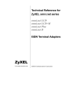
3.
Connect the power adapter. Plug one end of the power adapter to the round
POWER JACK on the back of the modem. Plug the other end to an AC wall
outlet. You can leave the power adapter plugged in when you are not using
the modem. To prevent power surges from damaging your modem and
computer, it is recommended that you connect the power adapter to a surge
protector.
Power
Switch
To
Power
Supply
To Serial
Port
To Line
(wall jack)
To Phone
Caution: Use only the power adapter supplied with your modem. Never
use a power adapter designed for a different product.
4.
Connect the serial cable. Plug one end of the serial cable into the SERIAL
connector on the back of the modem. Plug the other end of the serial cable to
the back of your computer. Your Omni 288S comes with a high-speed serial
interface capable of reaching DTE speeds of 460.8Kbps. Be sure that your
PC serial port has a high-speed 16550 compatible Universal Asynchronous
Receiver Transmitter (UART).
Note: Many older computers use a slow 16450 UART. This UART was
not designed for high-speed communications and will
significantly impede the performance of the Omni 288SS. To
check whether your computer has a 16550 compatible UART,
use a utility such as Microsoft Diagnostics (MSD) to verify the
2-1
Chapter 2 - Installation
type of UART installed in your computer. If your computer has
a 16450 UART, either replace it with a 16550 UART or add a
serial card with a 16550 UART to your system.
5.
Connect the telephone cord. Plug one end of the supplied telephone (RJ-11)
cord into the LINE jack on the back of the modem. Plug the other end into a
telephone wall jack, just as you would a standard telephone.
6.
Turn the computer back on.
7.
Turn the Omni 288S back on by raising the power switch. The PWR LED
should come on and the modem performs a self-test procedure.
Note: If the modem’s SQ LED is flashing, it has failed the self-test.
Consult Chapter 13 of this Manual for troubleshooting
information.
Optional Steps for Omni 288S Installation
The Omni 288S is equipped with a telephone jack and speaker and microphone
jacks on the back panel. The following sections briefly describe how to take
advantage of these features.
Telephone Jack
Connect a telephone to the PHONE jack on the back panel of the modem to
manually dial and answer calls when the modem is not exchanging data.
Microphone
To connect an external microphone, connect it to the modem’s MIC jack on the
back of the modem. The microphone jack can accommodate input from a standard
600 Ohm microphone.
Speaker
To connect an external speaker, connect it to the modem’s SPK jack found on the
back of the modem. The modem’s speaker jack accommodates a single 8 Ohm
2-2
Chapter 2 - Installation
speaker. To connect two speakers, obtain a dual-plug adapter that allows the
modem speaker jack to drive both speakers. This adapter can be found at most
electronics stores.
Driver and Software Installation
This section contains step by step procedures for installing the Windows 95 and
NT drivers, and configuring Dial-up Networking for the Omni 288S.
Windows 95 Driver Installation
Open the Control Panel by double clicking the "Control Panel" icon in your "My
Computer" folder.
Double click "Modems.” Then click the "Add" button. The following dialog box
will appear.
Select "Don't detect my modem; I will select from a list..” Then click "Next.”
Click the "Have Disk" button.
2-3
Chapter 2 - Installation
Insert the ZyXEL Windows 95 driver disk into your floppy drive and click OK. If
you have downloaded an updated INF file from ZyXEL’s FTP, Website, or BBS,
use "Browse" to find the location of the updated .INF file, click "Open.” Then
click "OK.”
Select Omni288S from the list. Then click "Next.”
Select the COM port your modem is connected to and click "Next.” A final
dialog will appear. Click "Finish.” You should see a window similar to the one
below.
2-4
Chapter 2 - Installation
Click "Close.” This completes the installation of your Omni 288S modem driver.
You may now use programs such as "Dial-Up Networking" with your ZyXEL
modem.
Windows 95 Dial-up Networking
If you have not installed the Dial-Up Networking feature in Windows 95, please
install it before you continue.
Double click on the "My Computer" icon and then double click on the "Dial-up
Networking" icon. From within the Dial-up Networking folder, double click on
the "Make New Connection" icon.
Choose a name for your connection and select your modem type from the drop
down window. Then click on the "Next" button.
2-5
Chapter 2 - Installation
Enter the phone number to your ISP or whatever host you are calling into. Click
on the "Next" button.
Click on the Finish button. A new icon is created in the Dial-up Networking
folder.
Right click on this icon. Then select "Properties" from the menu.
2-6
Chapter 2 - Installation
Make sure your Omni modem appears in the "Connect Using.” Then click on the
"Server Type" button.
These options are mostly host or server specific.
If you are using PPP, use the default settings shown above.
If you are logging on to an Internet connection, then select "TCP/IP.”
If you are connecting to a LAN, then select "Login to Network.”
If you are logging on to a Microsoft Windows network, select "NetBEUI.”
2-7
Chapter 2 - Installation
If you are logging on to a Novell network, then select "IPX/SPX
Compatible.”
Once complete click on "TCP/IP Settings.”
If your host requires you to specify an IP address (Static IP), then click on the
"Specify and IP address" radio button and enter your IP address. If your host
assigns an IP when you log in (Dynamic IP), then leave the "Server assigned IP
address" checked. Most servers assign an IP to you when you log in.
Click the "Specify name server address" radio button and enter your primary and
secondary DNS (Domain Name Server) IP.
In most cases, you should leave "Use IP header compression" and "Use default
remote gateway" checked. When all of the selections have been made, click the
"OK" buttons on all three opened dialog boxes.
This completes the remote connection definition. Locate the new connection icon
in your "Dial-up Networking" folder, and double click on it.
2-8
Chapter 2 - Installation
If the User name and Password are incorrect or missing, type them in. Click on the
Connect button and your Omni 288S will dial the number and establish a
connection to your Internet Service Provider.
Note: The default protocol for Dial-up Networking is Point-to-Point
Protocol (PPP). If your ISP requires you to use Serial Line
Interface Protocol (SLIP), you may need to create a special
logon script file. Because the procedures for logging on with
SLIP accounts vary greatly from ISP to ISP, you should consult
the technical support department of your service provider for
this information.
Setup for DOS Fax/Modem Software
After installing the Omni 288S, use the following procedures to verify your
modem connections.
1.
Install and load your communications software. If you need assistance, refer
to the manual that came with the software.
2.
If your communications software requires you to select a modem, and the
ZyXEL Omni 288S is not one of the choices, you can either check our web
site for the driver or select the ZyXEL U-1496 modem. In many cases, the
commands for these modems are identical.
2-9
Chapter 2 - Installation
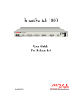
3.
Select the following communication settings:
Setting
Value
Baud rate
57,600bps
Data bits
8
Parity
None
Stop bits
1
Flow control
Hardware
Initialization string
AT&F
Port
COMn*
Note: When specifying a port assignment, the ‘n’ indicates the
computer serial port to which your modem is attached. For
example, if your modem is connected to serial port 2, you would
select COM2.
4.
Place your communications software in terminal or direct connect mode
(your communications software manual will explain how).
5.
Look at the modem’s front panel and verify the DTR LED is ON. If this LED
is OFF, your communications software is not addressing your modem at the
correct COM port. Make sure your software is set up for the same COM port
to which your modem is connected.
6.
Type AT and press the Enter key. You should see the AT characters you
typed, followed by an OK result code. If you do not see an OK result code,
turn the modem off and on, then repeat this step. If you still cannot see the
characters, refer to Chapter 13 for troubleshooting suggestions.
7.
Type ATDT number and press Enter, where number is your modem’s
telephone number. You should see a BUSY result code. If you do not see a
BUSY result code, refer to Chapter 13 for troubleshooting suggestions.
If you are not able to successfully complete this test and have already followed
the appropriate troubleshooting procedures Chapter 13, please call ZyXEL Tech
Support at 714-693-0808.
2-10
Chapter 3 - Basic Modem Operation
Chapter 3 - Basic Modem Operation
This chapter covers the basic commands and techniques involved in modem
operation. In many cases, this is the only information you will need in order to get
your Omni 288S up and running with communication software, and to start making
connections with your Omni 288S.
Understanding AT Commands
The Omni 288S communicates asynchronously with computers using AT
commands. AT commands are used to configure and control the Omni 288S.
Commands are usually sent to the modem by way of communication software, but
can also be entered manually by the user with the computer keyboard.
Command statements must be written in a specific form in order for the Omni
288S to recognize them. A command statement always begins with the letters AT
or at. It is then followed by one or more commands and the <Enter> key.
AT commands can only be issued when the Omni 288S is in “command mode” or
“off-line.”
Once the Omni 288S has established a connection with another modem it is said
to be “on-line” or in “data mode.” In this mode, the characters sent to the Omni
by your computer are transmitted to the remote modem rather than being
interpreted by the Omni as commands.
Using the Windows 95 Hyper Terminal Program
In order to issue an AT command statement, you first need to run a communication
program such as the Microsoft Windows “Hyper Terminal” program. This
program provides a simple method to manually enter AT commands so you can do
such things as “customize” the settings of your Omni 288S, or store phone
numbers you commonly will connect to.
Once the Omni is connected to your computer’s serial port and telephone line,
Open the Windows 95 “Accessories” program group, and open the Hyper
Terminal Program.
The program will prompt you for a name and Icon to use for your new connection.
Type the name Test Connection and press <Enter>.
Next, you will be prompted for country information, area code and phone number,
and the device used to make the connection. For this test purpose, do not enter a
phone number; simply choose the COM port your Omni is connected to from the
“Connect Using” list. Click “OK” when finished.
The next window sets the COM port settings. The settings used for The Omni
288S should be as follows.
3-1
Chapter 3 - Basic Modem Operation
Bits per second:
Data bits:
Parity:
Stop bits:
Flow Control:
57600
8
None
1
Hardware
Click “OK” when finished. After you have done this, save your new connection
by selecting “Save” from the “File” menu and click “OK.” A new connection
icon will be added to your Hyper Terminal folder.
You are now ready to start entering AT commands.
In the terminal window, type:
AT<Enter>
Omni 288S responds
OK
This confirms that the modem and your computer are communicating correctly.
To test the telephone line connection issue the manual answer command.
Type:
ATA<Enter>
The Omni 288S will pick up the phone line, and try to communicate. Normally,
this command is only used to answer an incoming call made from another modem.
Thus the high pitched noise you will hear from the speaker. To abort the
operation, press any key, or select “Disconnect” from the “Call” menu.
Dialing and Answering Techniques
Depending on what communications software you use to make modem
connections, you may not have as much control of how the modem dials the
telephone number. This section shows some useful examples of the AT commands
used for dialing and answering operations. The command characters specific to
each function are shown in bold type.
Dialing using the ATD Command
Touch Tone Dialing:
ATDT 555 1212
Pulse Dialing:
ATDP 555 1212
Tone and Pulse Dialing:
ATDP 555 1212 WT 24
Dialing Through a PBX:
ATDT 9 W 555 1212
Note: The 'W' in the dial string will cause the modem to wait for a
second dial tone before it continues to dial.
3-2
Chapter 3 - Basic Modem Operation
Pausing During Dialing:
ATDT 9,,555 1212
Note: The pause time for each comma is defined by S Register S8.
Default is 2 seconds per comma.
Dialing Without Waiting for Dial Tone:
ATX0D, 555 1212
Originating a call using an Answer Tone: ATDT 555 1212,,,,,,R
Redialing the Last Number Called:
ATDL
Waiting for Five Seconds of Silence:
ATDT 800 555 1212 @
123456,1 714 555 1212
Transferring a Call (using flash hook):
ATDT! 2468
Auto-Answer and Hook Controls
Enabling Auto-Answer:
ATS0=n
Note: In this example, n is a number from 1 to 255 that corresponds to
the number of rings after which your modem answers an
incoming call.
Disabling Auto-Answer:
ATS0=0
Manually Answering a Call:
ATA
Take modem off-hook:
ATH1
Hang up modem (on-hook):
ATH0
Manually Disconnecting a Call:
+++ATH
Making Your First Connection
For this example, we will use the connection you created in the Hyper Terminal
program to dial the ZyXEL BBS. If you are using a different terminal program, run
the program according to the instructions provided with it.
Start the terminal program by double-clicking the Test Connection icon. When
the terminal window appears, enter the dial command with ZyXEL’s BBS as the
phone number.
Type:
ATDT17146930762<enter> (Omit the ‘1714’ if you are in this area code)
The modem will go off-hook, dial the number, and after a few seconds of
negotiation tones, you should be connected to our BBS.
You will receive a login message asking for your name. For the purposes of this
example you need not continue. Just click the “disconnect” icon on the toolbar.
3-3
Chapter 3 - Basic Modem Operation
Quick Tips when issuing AT Commands
The ENTER or RETURN key must be pressed to execute a command.
Multiple AT commands can be combined into one line. For example,
AT&D2 and AT&N0 can be combined into one line AT&D3&N0.
The Omni 288S processes commands from left to right. The AT command
that appears to the right might over-write the command to the left if they are
trying to accomplish tasks or set modes that cannot coexist.
If you see duplicated characters for each one you type, your Omni 288S and
software both have their “echo” feature turned. The Omni 288S command
echo state is switched off using ATE0 and on using ATE1 (default). To
eliminate the double characters, turn off the software’s command echo rather
than using the ATE0 command. If you see no characters in your terminal
window when you type, the modem’s echo setting is probably set to off. In
this case, issue the ATE1 command.
When a command is successfully issued and accepted, a modem responds
with what is called a “Result Code.” The Omni 288S supports both
“verbose” result codes (i.e. “OK”), and “numerical” result codes (i.e. “0").
You can use the ATV command to set it one way or the other as follows.
Command
ATV0
ATV1
There are a few basic commands that do not require the “AT” command
prefix. These are as follows.
Command
A/
A>
<any key>
+++
Description
Select numerical result code
Select verbose result code
Description
Repeats the last issued AT command once
Repeats the last issued AT command once, or re-dials
the last dialed number up to 9 times until a key is
pressed or a connection is made.
Terminates the current connection attempt, if pressed
while modem is handshaking.
Escape code sequence. Entered while the modem is in
Data Mode. Returns modem to Command Mode.
The Omni 288S supports several groups of AT commands:
AT Command Set/Type
Basic AT (Hayes compatible)
Basic AT$ (on line help)
Extended AT& commands
Extended AT* commands
Example
ATB0
AT$
AT&N0
AT*I1
3-4
Chapter 3 - Basic Modem Operation
AT Command Set/Type
Fax and Voice AT+ commands
S-Register command
S-Register bit-mapped command (set S-
Example
AT+FCLASS=2
ATS0=1
ATS13.1=1
Register bit 1 equal to 1)
S-Register inquiry command
ATS0? Or ATS13.1?
You may browse the lists of available commands for each command set by using
the on-line help commands: AT$, AT*$, AT&$, and ATS$. Further detail on AT
commands will be covered in the chapters that pertain to their uses.
Modem Result Codes
When you execute or try to execute an AT command, your modem sends a result
code to let you know whether the command was executed. An OK result code
means the AT command you sent was executed. If you receive an ERROR code, it
means the command was invalid.
The Omni 288S also provides result codes that show:
Whether or not a Dial Tone was detected when the modem originated a call.
If a busy signal was detected when the modem originated a call.
If a remote telephone ring was detected when dialing.
The speed, protocol, and error control / data compression method used.
If your modem has detected an incoming ring.
Result codes can originate from any of eight result code sets. The ATXn
command lets you choose which set of result codes your modem uses. By default,
your modem uses result codes equivalent to the ATX5 command.
The result code options will be covered more thoroughly in later chapters.
Viewing S Register Values
Status registers (or "S-registers") contain values that determine the modem’s
operating characteristics. Whenever you send an AT command to your modem,
you are actually changing the value of an S-register.
You can use the Sr? command to view the value of S-register ‘r’. For example,
to view the value of S-register S0, which controls auto-answering, type ATS0?
and press Enter. The modem responds with a three-digit character showing the
value of this register, followed by OK. A value of 002, for example, means your
modem will auto-answer incoming calls after the second ring.
Some S-registers are bit mapped. For these registers, you can use the Sr.b?
command to read their values.
3-5
Chapter 3 - Basic Modem Operation
For example, to read the value of S-register S35, bit 7, type ATS35.7? and press
Enter. The modem responds with an appropriate value, followed by OK.
Changing S Register Values
You can use the ATS0=n command to change the value of an S-register.
For example, to have your modem auto-answer an incoming call after two rings,
set S-register 0 to 2. Be sure the n value is between 1 and 255. If n is set to 0,
your modem will not answer incoming calls.
Non-Volatile Memory
The Omni 288S has an amount of memory set aside for storing user information
such as frequently used phone numbers and default command settings. This latter
is particularly useful when you use your modem to call a variety of different
locations that require different settings. For this reason, the Omni 288S provides a
number of user “Profiles” that can be accessed through simple AT commands.
This section covers the topics of storing phone numbers, and saving default
settings in the power-on profile.
Storing Phone Numbers
The AT command to store a phone number is in the format AT&Zs=n.
The ‘s’ is a number from 0 to 49 that represents the location in memory that the
phone number is to be stored, and the ‘n’ is the phone number itself.
Example: To store the number ‘1-714-555-1212’ in memory location ‘2’, type:
AT&Z2=17145551212<Enter>
You can store up to 50 telephone numbers.
Dialing Stored Phone Numbers
The AT command syntax used to dial a store number is ATDS=n.
The ‘n’ is the memory location of the stored number you want to dial.
Note: As a general rule, when a letter in an AT command definition is
shown in italic type, the letter is not to be entered as part of the
command, but rather is representative of a number or string
expected as input. For example: The letter ‘S’ in the ATDS=n
command is actually typed, unlike the ‘s’ in the AT&Zs=n
command which represents a number.
3-6
Chapter 3 - Basic Modem Operation
Saving Settings and User Profiles
There are some cases where you may wish to save the settings you have made as
the default settings that are recalled when the Omni 288S is powered up. The
AT&WZ command selects the current settings as the power-on profile.
There are four profiles that can be changed by the user, and one factory default
profile. The following table lists the syntax for the command involved in storing,
recalling, and viewing the profile settings.
AT&Vn
Views the settings in profile (n-1); n=0 to 5; n=0 views current settings
AT&Wn
Stores the current settings in user profile ‘n’; n=0 to 3
ATZn
Resets the current settings with the settings in profile ‘n’, n=0 to 4
Profiles 0 to 3:
User profiles
Profile 4:
Factory default profile
Helpful Hints for PC Computers
Most PCs are equipped with more than one serial port. Standard cables are
readily available from many suppliers. Usually, serial ports are manufactured in
two forms, either with a 25-pin male jack or a 9-pin male jack. For high speed
serial connections at 230.4Kbps or 460.8Kbps, use a low-capacitance cable.
Also, keep the cable as short as possible.
The serial port is driven by interrupts. Every interrupt needs a certain amount of
overhead processing time. Too many interrupts reduce the computer's efficiency.
The UART 16450 is very commonly used in serial port devices. For every
character (byte) received, it generates an interrupt. If your hardware allows it and
if your software supports it, replace the 16450 UART with a 16550 model. This
newer chip has an internal buffer and generates an interrupt for up to every 16
characters (several trigger levels are available). With this UART installed, you
may drive your serial port at 57600 bps and above.
While data is written from the transfer-buffer to your hard-disk, characters may be
lost at the serial port. This is due to the fact that disk-access interrupts have a
higher priority than serial port interrupts. If you are running at a high serial speed,
e.g. 230.4Kbps or 460.8Kbps, on your PC, be sure to enable the disk cache by
including SMARTDRV execution in your AUTOEXEC batch file.
Default Modem Settings for PC’s
The Omni 288S factory settings are configured for operation with PC type
computers and comm software. In most cases, no additional settings will be
required. The following are some of the default settings that are used for
operation with PC computers and software.
3-7
Chapter 3 - Basic Modem Operation
AT Command
E1
&C1
&D2
&K4
&N0
Description
Echoes command characters
Carrier detect follows remote carrier
Modem disconnects on DTR on-to-off transition
Use both V.42 and MNP 4 error correction, and use
both V.42bis and MNP 5 data compression
Modem negotiates highest possible connection speed
ZyXEL Serial/Parallel I/O Card
For high-speed PC to modem communication, ZyXEL produces the special I/O
adapter card. This card includes a serial port and a parallel port, each with
special features, particularly when working with a ZyXEL modem, for example:
The serial port is 16550-compatible for most comm software's usage. It has a
speed of up to 460.8Kbps and data loss errors will not occur when working with
a ZyXEL modem's serial port. This solves high-speed communication problems in
Windows and other multi-tasking systems. The serial port has a 32-byte
transmission and a 32-byte receival FIFO to increase any comm program's
efficiency.
Helpful Hints for Mac Computers
Special AT Command Settings for Mac
For operation with Mac computers, you may use the factory default settings with
one exception. You must set the modem to ignore the DTR signal as follows.
Type:
AT&D0<enter> (set modem to ignore DTR)
AT&WZ<enter> (saves the settings to power-up profile)
Mac Serial Port
When you connect your Omni 288S modem to a Macintosh computer, make sure
the cable is a hardware handshaking cable. These cables are readily available.
The models Lisa, Macintosh 128 and Macintosh 512 don't have hardware
handshaking. The serial port on these (very outdated) models is provided as a 9pin connector similar to that of a PC. The serial port on all other Macintosh
models is a Mini-8.
Mac Software Tips
All terminal programs which make use of the hardware handshaking feature can
be used on the Apple Macintosh. Such programs are readily available as PD,
shareware or commercial software. One of the most powerful shareware
programs available is ZTerm.
3-8
Chapter 3 - Basic Modem Operation
Fewer programs are available to make use of the ZyXEL's fax features. A
commercial software which has found wide acceptance is FaxSTF. It is installed
like a printer driver, thus allowing you to send faxes from almost any program
which runs on your Macintosh. At the same time it allows automatic fax receiving.
This program includes a powerful line manager software which makes sure that
the fax software does not interfere with other programs using the serial ports. If
the modem is turned off when you start your Macintosh with the line manager
activated, the computer may seem to freeze for a few minutes. During this time the
line manager software tries to locate and to set up the modem. Turn on your
modem before you start your Macintosh to avoid this delay.
MaxFax is another fax software for Macintosh computers. On top of the fax
handling, it allows you to make use of the Omni’s voice features.
Drivers are available which allow use of the serial ports at speeds up to 230.4
Kbps. These drivers are currently available for Power Macs and AV Macs only.
Helpful Hints for UNIX-Based Computers
Serial Cable
Please consult the documentation that came with your workstation to find the part
number of or information on how to make a serial cable for your workstation. The
cable should be a hardware-handshaking cable. Please refer to Appendix A for a
complete list of signals provided by the modem its serial port.
Basic Modem Settings for UNIX
Unix environments usually don’t like modem responses or echoing of commands.
Therefore you should set ATE0Q1.
Depending on your of Unix, the cable and software used, you may have to disable
carrier detection using AT&C0.
Unix Software Tips
In order to use your ZyXEL modem from a terminal screen or an X-Windows
application, you need a program such as minicom or seyon, respectively.
If you wish to make use of the ZyXEL modem' special features such as voice,
special gettys such as mgetty or vgetty are needed. These programs are avaiable
from several ftp-sites. Some archives also contain source files.
You should suppress the modem's result codes (ATQ1) because some
applications may be confused by them.
3-9
Chapter 4 - Advanced Data Communications
Chapter 4 - Advanced Data Communications
This chapter is included as a general reference to the connectors, interfaces,
protocols, and standards used by the Omni 288S, including definitions of many of
the communications-related terms used in this manual.
Front Panel LEDs
The Omni 288 has 13 front panel LEDs. Some LEDs have individual meanings,
while others work in combination to apprise you of your modem’s operating
status. For example, the AA LED is ON when auto-answering is enabled, while
the V34 and V32b LEDs together show the connection mode and speed.
Refer to the following tables for details on the LED status indicators and their
meanings.
LED
AA
CD
TXD
RXD
DTR
DSR
RTS
CTS
EC
SQ
OH
State
ON
OFF
ON
OFF
ON
ON
ON
ON
ON
ON
ON
Blinking
ON
Flashing
ON
OFF
Indicates Status
Modem will automatically answer incoming calls.
Modem will not auto-answer incoming calls.
Modem has detected a valid carrier signal, or &C0 is set.
No carrier detected.
Computer is transmitting data to the modem.
Computer is receiving data from the modem.
Computer is ready for data communications.
Modem is ready for data communications.
Computer requests to send data.
Modem is ready to accept data for transmission.
Modem is using V.42 or MNP 4 error correction, or V.42bis
or MNP 5 data compression.
Data is being re-transmitted.
Good signal quality
Marginal signal quality or error condition at power-up.
Modem is accessing telephone line.
Model is off-line or not accessing the telephone line.
4-1
Chapter 4 - Advanced Data Communications
LED
V34
OFF
OFF
ON
ON
V32B
OFF
ON
OFF
ON
Indicates Status
Modem is in V.22bis, V.22, or mode slower than 9600bps.
Modem is in V.32bis or V.32 mode.
Modem is in V.34 mode.
Modem is in a ZyXEL proprietary mode
(ZyX 19.2, ZyX 16.8, or ZyCellular).
DTE Interface
DTE and DCE are terms used in data communication. DTE stands for Data
Terminal Equipment and DCE stands for Data Communication Equipment. The
computer or terminal is the DTE and the modem is the DCE. The DTE interface
used by the Omni 288S is an RS-232 with throughput speeds up to 460.8 Kbps.
Synchronous and Asynchronous Communications
There are two kinds of serial data communication. One is called synchronous, and
the other is called asynchronous. In synchronous communication, data is
transmitted and received bit by bit and is timed by an accompanying clock signal.
In asynchronous communication, data is sent character by character (or octet by
octet), and the idle time between characters is variable. Since no clock signal is
sent, character timing is recovered from the data itself.
A PC's COM1 and COM2 are asynchronous serial ports. Most PCs' and UNIX
systems' serial data communications are asynchronous. The serial data
communication on an IBM mainframe or mini is synchronous.
UART
A UART (Universal Asynchronous Receiver Transmitter) is the device used in a
DTE or DCE for asynchronous data reception and transmission. The standard
UART device used in PCs is of the NS16450 type. For high-speed serial data
transfers (38400 bps and up), the PC may not serve the UART fast enough and
data may be lost. In this case, a UART with data buffer is needed, such as the
NS16550A type device.
Serial Port
A serial port is the serial data connector together with its internal circuit on the
DTE or DCE with electrical and mechanical characteristics according to RS232C. Since some signals travel from the DTE port to DCE port, and some
signals travel in the opposite direction, the signal pin is a transmitter on one port
and a receiver on the other. The DTE serial port is different from the DCE serial
port in terms of signals on the connector pins. There are also mechanical
differences in terms of male (with pins) or female (with holes) connectors.
4-2
Chapter 4 - Advanced Data Communications
RS-232C or EIA-232D/E
RS-232C is the Recommended Standard (RS) of the Electronic Industries
Association (EIA), defining the serial communication interface between a DTE
and a DCE. The 232 is basically a serial number for the defined standard.
Sometimes it is necessary to redefine a standard, or to revise it. The most
commonly used revision of the RS232 standard is the "C" revision. For the "D"
revision, the prefix was changed to EIA. Except for a few signals which were
added but not commonly used, there is no practical difference between the "C"
and "D" revisions. There is now a new revision with the "E" suffix. The RS-232C
standard is equivalent to the ITU-T V.24 and V.28 standard.
Serial RS-232C Cable
A serial RS-232C cable is used to connect a DTE port to a DCE port. Do not use
a null-modem cable (which may be used to connect two DTEs directly with each
other through their serial ports). A normal RS-232C connector has 25 pins, and a
normal RS-232C cable has 25 wires. Many signals in the RS-232C are not used
in common applications, and a 9-wire RS232C cable is sufficient in most
applications. The PCAT's serial port has only 9 connector pins, thus eliminating
unnecessary pins. For high-speed DTE-DCE communication, use a lowcapacitance cable (as short as possible).
Communication Protocols and Speeds
The ITU-T or ITU-TSS (International Telecommunications Union Telecommunications Standardization Sector) is the international standard-making
body for telecommunications. Their primary function is to draft recommendations.
The recommendations they make for modem applications have a "V" prefix and
are called V-series recommendations. The most commonly used ITU-T modem
standards for 2-wire dial-up lines are summarized in the chart below.
Standard
Speed (bps)
V.34
28,800 ~ 2 400
V.32bis
14,400 / 12,000 / 7,200
V.32
9,600 / 4,800
V.22bis*
2,400 / 1,200
V.22
1,200
V.21
300
V.23
1,200 / 75
* bis is the old French word for second
In the USA, Bell Systems used to create de facto standards such as Bell 212A for
1200 bps modems and Bell 103 for 300 bps modems. Everyone follows the ITUT standards now for newer and higher-speed modems. The Omni 288S supports
all the above mentioned modem standards and are compatible with existing
modems.
4-3
Chapter 4 - Advanced Data Communications
Universal Protocol Compatibility
Universal compatibility covers a broad range of ITU-T and BELL standards, and
provides data compression.
Various operation modes that can be achieved are as follows:
Standard
V.34
ZyXEL
ZyXEL
V.33*
V.33*
V.32bis
V.32bis
V.32bis
V.32
V.32 uncoded
V.32
V.29*
V.29*
V.29*
V.27bis*
V.27bis*
V.26bis*
V.23
V.23
V.22bis†
BPS rate
(+/-0,01%)
28 800 - 2 400
19 200
16 800
14 400
12 000
14 400
12 000
7 200
9 600
9 600
4 800
9 600
7 200
4 800
4 800
2 400
2 400
1200 / 75
600 / 75
2 400
Baud rate
(+/-0,01%)
multiple
2 743
2 400
2 400
2 400
2 400
2 400
2 400
2 400
2 400
2 400
2 400
2 400
2 400
1 600
1 200
1 200
1200 / 75
600 / 75
600
Modulation
128-TCM
64-TCM
128-TCM
64-TCM
16-TCM
32-TCM
16-QAM
4-DPSK
16-QAM
8-QAM
4-DPSK
8-PSK
4-DPSK
4-DPSK
FSK
FSK
16-QAM
V.22†
1 200
600
4-DPSK
V.21
BELL 103
G3 FAX
Cellular Modes
300
300
FSK
300
300
FSK
Implemented according to T.30, V.17,V.29 and V.27ter.
ZyXEL proprietary cellular modes; 14400 bps to 4800 bps.
multiple
Carrier Freq
[Hz]
multiple
1800
1800
1800
1800
1800
1800
1800
1800
1700
1700
1700
1800
1800
1800
1200 Orig.
2400 Ans.
1200 Orig.
2400 Ans.
Choosing the Modem Link Options
The Link options or protocol negotiation settings are controlled by the &N
command. The default setting is &N0. The modem will execute an auto-handshake
sequence to determine the protocol being used by the remote modem, and connect
at the highest allowable speed.
The link options can also be set to force negotiation to any one of the protocol
options listed in the above table using &N1 to &N73. If the modem cannot
successfully negotiate the protocol that was set, connection will be refused, and
the modem will release the line. For specific settings, please refer to Chapter 11.
4-4
Chapter 4 - Advanced Data Communications
Certain modes, such as the ZyXEL proprietary modes, Fax mode, and Cellular
modes can be added or omitted from the auto-negotiation process using the Sregisters settings listed below.
Mode
ZyXEL 19200
ZyXEL16800
G3 Fax
Cellular
Disable
S43.1=1
S43.0=1
S38.4=1
S43.3=1 *
Enable
S43.1=0 *
S43.0=0 *
S38.4=0 *
S43.3=0
* Denotes default setting.
Setting the DTE to DCE Rate
The Omni 288S DTE to DCE rate can be determined in three ways:
1.
By default the DTE to DCE rate is equal to the DTE speed set by S20
(default S20=1 for 115200 bps). This mode is set with &B1.
2.
To set the DTE to DCE rate to follow the connect speed, set &B0.
3.
To force the modem to use a fixed baud rate when answering, set S18 to the
corresponding value.
S18=
0*
1
2
3
4
5
6
7
8
9
10
11
12
13
14
Speed
Disable fixed rate
115200 bps
76800 bps
57600 bps
38400 bps
19200 bps
16800 bps
14400 bps
12000 bps
9600 bps
7200 bps
4800 bps
2400 bps
1200 bps
460800 bps
S18=
15
16
17
18
20
21
22
24
25
26
27
28
29
32
46
Speed
300 bps
307200 bps
153600 bps
102400 bps
61440 bps
51200 bps
624000 bps
124800 bps
62400 bps
41600 bps
31200 bps
24960 bps
20800 bps
230400 bps
921600 bps
* Denotes default setting
Error Control
Error control keeps the modem data link error-free by detecting and retransmitting erroneous data. ZyXEL modems support both MNP and V.42 error
control protocols. The MNP protocol was an industry de facto standard
developed and licensed by Microcom, Inc. ZyXEL modems support level 4 and 3
4-5
Chapter 4 - Advanced Data Communications
error control protocols, commonly denoted as MNP4 and MNP3. V.42 is a
standard developed by ITU-T. V.42 supports both LAPM (Link Access Procedure
for Modem) and MNP4. A V.42 handshake will try an LAPM connection first, and
if not successful, it will try MNP4.
The error control (MNP4, LAPM) methods in modem to modem connections are
based on techniques utilized by both modems. They are explained below.
CRC (Cyclical Redundancy Check) Error Detection
At the end of every data block, a 16-bit number CRC, which is calculated through
a polynomial function, is sent. The receiving modem receives the block,
calculates its own CRC through the same polynomial function, then compares the
numbers. If it matches the received CRC, everything is all right. If not, an error(s)
has occurred somewhere in the block. The modem checks every block received
for error(s).
Automatic Re-transmission Request (ARQ) Error Correction
Once a data block is received error-free, the receiving modem will acknowledge
this block immediately. The sending modem receives the acknowledgment and
will check if any block(s) is(are) not acknowledged. Let us assume 18 blocks
were transferred and the first 14 blocks were acknowledged. If no
acknowledgment for block 15 is received in a given time, this block must have
been damaged. Acknowledgments of blocks 16 through 18 are ignored. Blocks
starting from 15 are resent.
ARQ Error Correction with Selective Reject
ZyXEL modems support V.42 error control with selective reject. Using this
feature, the modem only re-sends the erroneous data block(s), not all the data
blocks starting from the one in error (just block 15 in the above example). This
saves retransmission time and greatly improves efficiency in high error rate
situations.
Data Compression
The Omni 288S supports both V.42bis and MNP5 data compression protocols.
Data compression works by representing the original data information in less bits
and transmitting the reduced data bits through the data link. The receiver recovers
the original information by reversing the representing process. The process of
representing original data in less bits is called redundancy removal.
Data compression needs an error-free data link to work correctly. MNP5 is used
with MNP4 error control and V.42bis is used with V.42 error control.
MNP5 data compression utilizes the run-length encoding and adaptive frequency
encoding techniques. V.42bis uses a string coding algorithm.
4-6
Chapter 4 - Advanced Data Communications
The compression efficiency of V.42bis is generally higher than that of MNP5. In
some cases it can be 50% to 100% higher and in other cases it is just slightly
higher. In general, it is about 50% more efficient.
Run Length Encoding
Run-length encoding is applied in an attempt to avoid sending long sequences of
repeated characters (data). When three or more repeated characters appear in
succession, only the first three tokens (representing the compressed format of that
character) and a repetition count will be sent.
Adaptive Frequency Encoding
Adaptive frequency encoding is applied after removing repeated characters
(data). In adaptive frequency encoding, a token is substituted in the data stream for
the actually occurring character in an attempt to send fewer than 8 bits for each
character. The token is generated from a dynamic tabulation of character
appearance frequency. The total number of available tokens is 256, of which only
the first 32 tokens are smaller than 8 bits, so random data will gain no advantage
from this technique.
String Coding
Instead of sending each data character individually, a token for a character string
is sent. The modem adaptively builds a dictionary of string tokens according to
data that appears. Omni modems support a dictionary size up to 2K string tokens.
The input data characters are combined and checked for a matching string in the
dictionary. The token is sent for the longest matched string. Compressibility is
high if there are some regularities of character pattern in the data.
The error control and data compression option can be enabled either from the or
the terminal. &K4 is the default. For some applications, like BBSs, where
transmission of already compressed files is usual, the MNP5 data compression
process actually produces more redundant data and slows down transmission.
Setting S38b5 will disable MNP5 protocol negotiation regardless of the error
control setting.
Hardware or Software Flow Control
Flow control determines how data will be transferred between your computer and
modem. Your modem supports two flow control methods. But regardless of
which flow control method you use, make sure your communications software is
configured to use the same flow control method that your modem is using.
Otherwise, you may experience erratic data transfer where portions of received
data are lost, or you will receive frequent errors during data transfers.
The flow control option is set by AT&Hn as follows:
4-7
Chapter 4 - Advanced Data Communications
&H0
disables flow control
&H3
sets CTS/RTS flow control
&H4
sets XON/XOFF flow control
Hardware CTS/RTS
This is a bi-directional flow control where CTS and RTS are RS232 signals
which must be available on your computer. When the modem's transmission buffer
is almost full, the modem will drop CTS to signal the DTE that it cannot accept
any more data. Turn ON the CTS to notify the DTE that it can keep sending data to
the modem. On the computer software side, when the receiving buffer of the
software is almost full, it will drop RTS to signal the modem to stop sending data
to the DTE. Turn ON the RTS and the modem will start sending data again to the
DTE. In asynchronous full-duplex applications, the Omni 288S always responds
to the RTS signal as a flow control signal. The Omni 288S defaults automatically
to this hardware flow control setting and it is a better choice.
Software XON/XOFF
This is a bi-directional flow control. XON and XOFF character defaults are
decimals 17 and 19. These can be changed by modifying the S-Registers 31 and
32. Both the modem and the DTE will treat XOFF as a signal to stop transmitting
data, and will treat XON as a signal to restart sending data. Modems will not send
these characters received from the local DTE to the remote modem.
4-8
Chapter 5 - Synchronous Mode Operation
Chapter 5 - Synchronous Mode Operation
This chapter introduces you to the use of the Omni 288S for synchronous
operation. The modem can be used as a synchronous modem when it is connected
to a synchronous computer or terminal. It is of course necessary to make sure that
the remote modem and system are also set to synchronous. Synchronous operation
applies to all of the non-FSK modes the modem is supplied with. Before
synchronous transfers are started, some initial settings should be made.
V.25bis Command Set
To enable V.25bis commands use the AT*I1 command.
For synchronous applications, the modem is permanently set in normal situations
for use with one application. Save the desired settings in the power-on profile,
and the modem will be initialized to synchronous mode (&M3) with V.25bis
command enabled (*I1) when turned it is turned on.
A special command RST is provided to get the modem back to asynchronous AT
command mode from V.25bis mode. You can enter this RST command in either
synchronous or asynchronous V.25bis mode.
Syntax
CRN
CRS
Command with Parameters*
CRN <dialstring>**
CRS n
PRN
PRN n; <number>
RLN
DIC
CIC
CFI
RLN***
DIC
CIC
CFI XX
INC
VAL
INV
LSN
INC
VAL
INV
LSN n; <number>
RST
RST
5-1
Description
Call request with number provided.
Call request with number from
memory, 0 # n # 49;
n is the memory location.
Saves <number> to address n
(0 # n #49).
Requests list of all stored numbers.
Ignores incoming call.
Accepts incoming call.
Call failure indication:
ET Engaged Tone.
NS Number is not stored.
RT RING Tone.
AB Abort Call.
NT Answer Tone is not detected.
Incoming call.
Valid.
Invalid.
List of stored numbers.
(Response to RLN)
Changes to the asynchronous
AT command mode.
Chapter 5 - Synchronous Mode Operation
Clock Options
Synchronous data must be transmitted and received with a common timing clock.
This timing clock is used to transmit data from the DTE to the modem which
modulates the data according to this clock. The receiving modem recovers the
clock and data from the carrier and sends the data to the receiving DTE along
with the clock. There are three types of transmission synchronous clock sources to
choose from:
1.
The internal clock is the one that suits most applications and is the default; in
this case, the clock signal is generated by the sending modem.
2.
The slave clock is used when in remote digital loopback mode.
3.
The external clock is a signal generated by the sending DTE.
INTERNAL
AT&X0
EXTERNAL
AT&X1
SLAVE
AT&X2
The modem provides the clock and sends it to the
DTE. Adaptive rate can be used. (Default)
The DTE provides the clock and sends it to the
modem. Must use auto-retrain, cannot use adaptive
rate.
Recovered receiver clock serves as transmission
clock.
RTS Options
There are two RTS options. The choice depends on application and host/terminal
requirements. In asynchronous mode RTS is used as a hardware flow control
signal.
IGNORED
AT&R1
CTS TRACKS RTS
AT&R0
RTS is ignored; always assumed to be ON.
(Default)
Delay before CTS responds to RTS's
change. The delay is set in the S26 register.
Command State Options
For synchronous data communication, there are two options you can choose from
to define how the modem will operate in the command state.
SYNC DATA
AT&M1
SYNC
AT&M3
The modem accepts asynchronous command in
command state, but exchanges data
synchronously in data state.
The modem accepts synchronous command
(V.25bis) and exchanges data synchronously
with a remote modem.
5-2
Chapter 5 - Synchronous Mode Operation
You can always use the panel operation to control and configure the modem and
use the manual dial and answer to operate the modem.
Dialing from Synchronous Mode
1.
Dial from the terminal using asynchronous commands. Set &M1 and use
asynchronous AT commands to dial the number. Once the modem is
connected, the modem will enter synchronous operation.
2.
Dial through the computer using V.25bis commands. Some communication
software packages on synchronous computers can dial using V.25bis
synchronous commands. In this case, set &M3 and *I1 and the modem will
accept V.25bis commands and make a synchronous connection.
3.
Using DTR to dial a stored number in synchronous mode. Store the
telephone number from the front panel STORE NUMBER menu or by the
asynchronous command &Zn=. Use the DEFAULT DIAL parameter menu or
*Dn command to select the default dial pointer. Set &D1 and either &M1 or
&M3, then raise DTR from your terminal or communication software. The
modem will dial the default stored number. After the modem is connected, the
modem will enter synchronous operation.
With S35b4 set, pressing the DATA/VOICE switch will also cause dialing of
the default number.
4.
Manual dial. Set the modem to synchronous mode (&M1 or &M3), then dial
a number from a telephone set. When you hear the answer tone, type ATD (if
&M1 is set). The modem will go into synchronous operation after connection.
Answering from Synchronous Mode
Auto-Answer
Set the modem to synchronous mode. Set the S-register S0 to equal the number of
rings before auto-answer occurs. Set it from the terminal (if &M1 is set) using the
asynchronous AT command, or select the STATUS REGISTER menu to change
the S0 value.
Manual Answer
Type ATA from the terminal (if &M1 is set).
5-3
Chapter 6 - Leased Line Operation
Chapter 6 - Leased Line Operation
A leased line is a permanent telephone line connection between two fixed points.
It can be dedicated copper wires or a leased telephone circuit from the telephone
company. 4-wire leased lines use one pair of wires to transmit data and a second
pair to receive. 2-wire leased lines transmit and receive on the same pair of
wires. The Omni 288S supports only 2-wire leased lines.
Connecting to a 2-Wire Leased Line
The Omni 288S is equipped with a phone jack for dial-up line connections.
Connections can also be made to a 2-wire leased line using the same jack.
Line Type Setting
AT-Command
AT&L1
Description
The modem is connected to a 2-wire leased
line; the line plug should be plugged into the
jack assigned LEASED LINE on the rear
panel.
For the normal dial-up line only models, only 2-wire leased lines can be used and
the same phone jack is used for both dial-up and leased-line connections. The dial
backup feature is not available in this case.
Power Level Setting
The Omni 288S’s leased-line mode transmission power level can be adjusted
from 0 dBm to -27 dBm in 1 dBm increments. If a dial-up model is used for 2wire leased-line connection, the transmission power is limited to -3 dBm.
AT-Command
AT*P0
AT*P15
Description
The default is -9 dBm. The adjustable range
is from 0 to -15 dBm, effective in leasedline operation only. If bit 3 of S35 is set,
this range will change to -12 to -27 dBm.
Leased Line Handshaking
In a typical dial-up connection, the originating modem dials the number and waits
for the answering modem's carrier signal. The answering modem can be
commanded to either answer the call immediately, or after a specified number of
rings.
In a leased-line connection, the communication circuit between two modems is
always present. Dialing and waiting for rings does not occur in this situation. If
these two modems want to establish a data link, one must be designated as the
6-1
Chapter 6 - Leased Line Operation
originator and the other as the answerer. You can set this manually or
automatically.
Manual Connect
Set the modem to leased-line mode. Type the asynchronous command ATD to the
originating modem and ATA to the answering. Use AT*Mn or set S14b0 to select
originate or answer mode.
Auto Handshake
If you want handshaking to occur automatically upon power-up, you have to save
the leased-line configuration to the power-on profile. How to designate a profile
to be a power-on profile is described in Chapter 3. Please remember to set the
handshake mode before you save the configuration. Be sure that one modem is set
to originate mode and the other to answer mode.
AT-Command
AT*M0
AT*M1
Description
When operating over a leased line, modem
will handshake in originate mode. (Default)
When operating over a leased line, modem
will handshake in answer mode.
Terminating a Leased Line Connection
Pressing the DATA/VOICE switch on the Omni 288S will switch the modem
on/off the connected leased line.
6-2
Chapter 7 - Cellular Mode Operation
Chapter 7 - Cellular Mode Operation
The Omni 288S is equipped with a special cellular communication mode which
enables the modem to perform reliable high speed data transmissions over
cellular phone links. Although all ZyXEL modems can provide the cellular mode,
the ZyXEL U-1496P portable modem is specially designed for mobile use. We
have nick-named the ZyXEL cellular mode as ZyCellular. This chapter not only
explains the ZyCellular mode, but also gives background information on cellular
data communications.
Cellular Phone Systems
We are referring here exclusively to the analog cellular phone system. It is called
AMPS (Advanced Mobile Phone Service) in North America. The cellular phone
system got its name by dividing its covered area into many small cells. Each cell
has a cell site radio station maintaining a radio link with every cellular phone that
is in use in the cell. If a cellular phone moves out of one cell's boundary and goes
into another cell, it will be instructed to switch its radio link to the new cell using
a new frequency channel. This is called cell hand-off.
By limiting the radio transmission power in each cell's radio communication, it
will not interfere with a distant cell's radio communication using the same
frequency. Frequency reuse is the principle of cellular phone systems to increase
the number of radio channels available.
Cellular Impairments
A common problem in cellular communication is cell hand-off. In the process of
cell hand-off, the radio link, hence the modem carrier, will be interrupted for 0.2
second to 1.2 seconds. A normal modem will respond with retrain which takes
about 10 seconds or may even hang up.
A cellular phone may be instructed to change its power depending on its distance
from the cell site station. The radio link will be interrupted for about 0.2 second.
An effect similar to cell hand-off will .
A particularly difficult cellular impairment for data communication is called
multi-path fading. A cellular phone receives the cell site station's radio signal
through many indirectly reflected paths. Due to the phase difference of the arriving
signals caused by the signals taking different paths, the combined signal,
depending on location, may be strong, weak or totally faded. A moving cellular
phone will experience a periodical signal weakness. This is called multi-path
fading. Fading will cause data errors because the carrier is lost due to fading.
The analog cellular phone system was designed for voice communications. It
employs companding (concatenated from compressing and expanding; it makes
small signals better at the sacrifice of large signals) and pre-emphasis which are
7-1
Chapter 7 - Cellular Mode Operation
good for voice, but not suitable for a modem signal. Modem signals, if too strong,
may saturate the cellular link and cause distortion. Modem signal power that is
too weak will result in lower signal-to-noise ratio at the receiving end. There is
an optimum power in cellular data communications, but it is different in each
case.
Cellular Modems and ZyCellular Technology
A truly cellular modem must handle the cellular impairments and maintain a
reliable data link with reasonable data throughput through a cellular channel.
Some modems claiming to be "cellular” lack most of these capabilities.
A link-layer-only protocol does not do anything to enhance modem data pump
performance or physical communication robustness. It does not help much to
handle cellular impairments.
ZyXEL developed special technologies for cellular data communications to
provide reliable, high throughput data links over a cellular channel. We call these
technologies ZyCellular. ZyCellular technologies specifically improve the
modem data pump's performance with respect to cellular impairments.
ZyCellular Modes
In addition to normal modem, fax, and voice operation modes, the following
cellular modes are available in the Omni 288S:
Mode
Multi-Auto
CELL 14400
CELL 12000
CELL 9600
CELL 7200
CELL 4800T
Speed
V.34/ZyX modes/V.32bis/V.32/V.22bis/G3 FAX/Cellular
14400/12000/9600/7200/4800
12000/9600/7200/4800
9600/7200/4800
7200/4800
4800
CELL 14400 will connect with another modem using cellular mode at a speed of
up to 14400 bps. It will also connect with another V.32bis/V.32 modem. The
actual speed depends on the line condition. The modem will automatically fallback or fall-forward within its speed range.
CELL 12000, CELL 9600, and CELL 7200 limit the maximum speed to 12000
bps, 9600 bps, and 7200 bps, respectively.
CELL 4800T uses a trellis coded modulation at 4800 bps speed. It has a better
performance than the uncoded V.32 4800 bps mode.
The modem will automatically and dynamically select and adjust to the best speed
and mode in which to operate. Selecting one of the above cellular modes only
limits the maximum speed at which the modem will operate.
7-2
Chapter 7 - Cellular Mode Operation
The MULTI-AUTO mode will automatically adapt to the other modem's
capability, and will request and connect the appropriate mode. If both sides have
cellular mode capability and at least one side is using a cellular phone, using
MULTI-AUTO to make or answer a data call will result in a cellular mode
connection. MULTI-AUTO is the default mode.
Cellular Mode Usage
Usage of the cellular mode is recommended when using a cellular link for modem
connections. It can also be used other bad line conditions such as a line with
frequent large impulse noise. ZyCellular mode is more noise resistant, impairment
resistant, and error resistant.
It is simple to use the ZyCellular mode. Everything is determined automatically by
the modem. The user only needs to set S-register S49 bit 7 and leave the modem
on MULTI-AUTO. The modem takes care of everything else.
S49b7 tells the modem where it is installed. If S49.7=0, the modem is installed in
an office connected to a normal telephone line; if S49.7=1, it means the modem is
a mobile unit connected to a cellular phone. When a ZyCellular modem calls or
answers another modem, it will indicate its cellular capability and whether it is
using a cellular phone. If both sides have the ZyCellular capability and at least
one side is using a cellular phone, the connection will automatically be a cellular
mode connection such as it would be if it were using CELL 14400 mode. If one
side is a normal non-cellular modem, the connection will automatically be a
normal modem mode.
If manual power setting is desired, set S43.2=1 to disable power adjustment
and use S49 bits 0-3 to set power -9 to -24 dBm.
If a cellular mode connection is desired, set S43.3=0 to enable the cellular mode
connection. The default for this option is to be disabled (S43.3=1).
You can also send and receive faxes on cellular links by setting S49.7=1 on the
ZyCellular modem that is using a cellular phone. Now your modem can send and
receive faxes to and from fax machines and other fax modems.
Cellular Modem Installation Examples
The most difficult part of cellular modem installation is connecting the modem to
the cellular phone. There is no standard on the interface and connector type that a
cellular phone should use or provide. Every cellular phone maker has its own
interface design. There isn't a standard way to connect a modem to a different
brand of cellular phone. Some vendors have made a specific adapter for each
model of cellular phone that will convert a specific cellular phone's interface to a
standard telephone company's 2-wire phone interface. A cellular modem can
connect to a cellular phone such an adapter.
7-3
Chapter 7 - Cellular Mode Operation
If you are using a cellular phone data interface adapter, the following figures
illustrate three installation examples. The figures are illustrated with a U-1496P
model. You can use the Omni 288S, in the same way.
The following is an example of a mobile phone that has a handset cradle and a
separate transceiver and handset.
The following is an example of a mobile phone that has a separate transceiver and
handset.
The following is an example of a one-piece hand-held mobile phone.
7-4
Chapter 7 - Cellular Mode Operation
Some newer cellular models, particularly the hand-held ones, have an audio jack
that can connect the cellular phone's audio input/output to an outside headphonemicrophone set. A simple adapter cable can be used to connect the RJ11 modem's
2-wire interface to this cellular phone's audio jack. In this case, you need to
manually dial or answer a call using the cellular phone to establish a phone
connection and then manually make the modem go on-line using the ATD or ATA
command.
7-5
Chapter 7 - Cellular Mode Operation
Office Installation
Naturally, you can install the Omni 288S in an office environment, as with all the
other ZyXEL models.
7-6
Chapter 8 - Special Functions
Chapter 8 - Special Functions
This chapter describes the special features of the Omni 288S, and offers
instructions on how each is used.
Security Functions
The Omni 288S provides a security function that prevents unauthorized users from
making connections. Two types of security functions are provided.
Type 1 security is used when the remote modem is also a ZyXEL modem.
Type 2 security is used when the remote modem is any other brand.
The type 1 connection, the dial-in (remote) modem will send in its supervisor
password for checking at the initial connection , and the local modem will check
this password against its pre-stored acceptable password list.
The type 2 connection, the remote terminal will be prompted to enter the
password at the initial connection and the local modem will do the password
checking.
Levels of Security
Two levels of security are provided:
With level 1 security, the local modem will maintain the connection if the
password is OK, otherwise the line disconnected.
With level 2 security, dial back the phone number corresponding to the dialin password. The line simply disconnected if the password does not match.
User Passwords
50 user passwords may be defined. The corresponding 50 dial-back numbers are
the the modem’s 50 stored phone numbers. Any character (ASCII 0-127) can be
used in the password, the maximum password length is 8 characters.
The security functions are only accessible through AT commands in terminal
mode. Any access attempt will result in the modem’s prompting to enter the
supervisor password the attempt will be rejected if the entered password is not
correct. The default supervisor password is ZyXEL when the modem is shipped
from the factory. This supervisor password is also the password sent for
automatic password checking in a type 1 connection. To modify the supervisor
password, use AT*HS.
You will be asked for the original password and a new password and then to reenter the new password for verification. For example:
Password: (Enter supervisor password)
8-1
Chapter 8 - Special Functions
********
Password: (Enter new supervisor password)
********
Verify: (Enter the new supervisor password again)
********
OK
The command AT*Hn will modify the nth user password. You will be prompted
to enter the supervisor password first and then be prompted to enter the nth user
password.
The command AT*V will list the 50 user passwords and the supervisor password
on the screen for viewing. Again, you will be prompted to enter the supervisor
password first.
The following commands will enable different types and levels of security:
Command
*G0
*G1
*G2
*G3
*G4
*G5
Function
Disable security function.
Enable type 1 and level 1 security, with password check.
Enable type 1 and level 2 security, with password check
and callback.
Enable type 2 and level 1 security, with password check.
Enable type 2 and level 2 security, with password check
and callback.
Enable type 2 and level 2 security, with password check
and callback, remote site enters the callback number.
Note: Before the security type or level changed, the modem requires
the supervisor password.
For type 2 security, the remote site will be prompted to enter the user password.
A maximum of 3 tries in 40 seconds is allowed. If a correct password is not
entered within this time limit the line will be disconnected. If the remote site is to
enter the callback number it will be prompted to do so.
Remote Configuration
Remote configuration on the Omni 288S is provided as a profile by profile
batch mode. When on-line, the remote modem’s current configuration or one of its
profiles can be read into one of the local modem’s user profiles. This profile is
modified locally and the line can be disconnected during this time.
8-2
Chapter 8 - Special Functions
Local profile modification is done by loading this profile as the active settings
and then modifying and saving the active settings back to the profile. Then the
connection is reestablished and the profile transmitted to the remote modem.
Reading a remote profile b into a local profile a is acheived by the command:
AT*Rab
a=0-3
Local user profile number
b=0-3
Remote user profile number
b=4
Remote active configuration
b=5
Remote factory default
Return the modems to on-line status again. The local modem can upload (write)
its profile to the remote modem’s profile and have the remote modem reset from
the new profile. This is done with the command:
AT*Wab
a=0-3
Local user profile number
a=4
Local active configuration
a=5
Local factory default
b=0-3
Remote user profile number
The remote profile read and write commands - *Rab and *Wab - only work in
the on-line condition. The connection speed and mode do not matter. The remote
modem must be set to accept remote configuration by executing the AT*F1
command. The AT*F0 command will set the modem up to deny remote
configuration requests. Because the modem uses the remote digital loopback mode
to request remote configuration information, the remote digital loopback request
must also be granted (AT&T4) on the remote modem to accept the remote
configuration request.
Batch mode remote configuration is a convenient feature allowing you to preconfigure a remote modem in one of the local modem’s user profiles and send it to
the remote modem in one action. It is particularly useful when there are many
remote modems and a set of standard configurations is available so you can store
them into user profiles. You just need to configure the remote modem into one of
the standard configurations by activating the remote configuration once.
8-3
Chapter 8 - Special Functions
Caller Number Delivery (Caller ID)
Caller Number Delivery (CND), commonly called Caller ID, is a new kind of
phone service that may be offered by your local phone company. Check your
phone company for availability. You must subscribe to it and usually pay an
additional monthly service charge this service.
With CND service, the phone company’s central office will send the coded caller
information to the called station. This information is sent once between the first
and second. The Omni 288S modem can decode this caller information and
present it to the connected computer/terminal during the second ring period as part
of the call progress ring message. The modem will also report the Caller ID
information if asked by the command AT*T.
There are two kinds of caller information message formats sent by the phone
company.
One is the single message format which includes date, time, and caller ID
The other is the multiple message format which also includes the caller name
as registered with the phone company.
The command ATS40.2=n is used to enable (n=1) or disable (n=0) the Caller ID
detection function. The default is disabled. Enable it only when you have this
service and want to enable its detection.
Note: The Caller ID message may cause some communication
software that is not expecting it to become confused. If you
plan to use the Caller ID feature, be sure you are using
software that supports it (such as ZFAX).
In single message format, the modem will send a ring message to the terminal as
follows:
RING
TIME: <MM-DD hh:mm>
CALLER NUMBER: <CALLER_ID> or CALLER
NAME:<CALLER_NM>
RING
MM is the two-digit month message, DD is the two-digit date message, hh is the
hour and mm is the minute of the time, and CALLER_ID is the phone number of
the caller or CALLER_NM his/her name.
The following is an example of a caller ID message as it might appear on your
screen:
RING
TIME: 04-28 12:30
8-4
Chapter 8 - Special Functions
CALLER NUMBER: 7135551414 or
Smith
CALLER NAME: Jack
RING
In the multiple message format, if the caller’s number and name are available, the
ring message will display both:
RING
TIME: MM-DD hh:mm
CALLER NUMBER: <Caller_ID>
CALLER NAME: <Caller_Name>
RING
Here is an example:
RING
TIME: 04-28 12:30
CALLER NUMBER: 7135551414
CALLER NAME: Jack Smith
RING
If the caller number and name are not available, the ring message will appear as
follows:
RING
TIME: 04-28 12:30
REASON FOR NO NUMBER: OUT_OF_AREA
REASON FOR NO NAME: PRIVACY
RING
The last CND message that the modem received can be displayed by using the
AT*T command.
Setting S48.0=1 will cause the modem to report CND information in its ASCII
coded hexadecimal raw data format. The DTE software is responsible for
explaining the data.
Notes: Please refer to the Bellcore Technical Advisory document ATNWT-000030 for the exact data format. The above Caller ID
scheme applies to the North America area. Different countries
may employ different Caller ID schemes, check if the scheme
used in your country is supported before using the Caller ID
8-5
Chapter 8 - Special Functions
feature. For most other Caller ID schemes, only the Caller
telephone number is provided.
Distinctive Ring
Distinctive Ring is a phone service that may be offered by your phone company.
Check your phone company for availability. With this service, you can have
several phone numbers assigned to the same phone line. The phone company will
send a different type of ring signal for each phone number being called. The
subscriber can distinguish which number is called by which type of ring is
received.
A simple use of this feature is that you can have three numbers on the same line
and you can list the three numbers for voice, data, and fax, respectively. You can
then have your fax machine answer only the ring corresponding to the fax number
and have your modem answer only the ring corresponding to the data number. The
voice call will not be answered by either fax machine or data modem and it will
only be answered when someone picks up the phone. Or you can have the
answering machine answer only the voice ring. A more complicated use is that
you can have one number for multiple uses, such as one number for both data and
fax.
A ring signal is a composition of repeated on and off states. Different types of
rings usually correspond to different compositions of the “ON” part (cadence) of
the ring. The Omni 288S modem can distinguish up to four types of ring signals
and can be commanded to answer or not answer any one of these four types of
ring signals. Following is a list of these four types of ring signals. These are the
ring types used in the USA. The difference among the ring types is the twosecond ON part of the ring signal. It comprises a long, double short, or triple short
ring.
S-register S40 bits 3-6 are used for distinctive ring control. Each bit controls the
answering of a particular ring type. Setting a bit to “1” (on) enables answering,
setting it to “0” (off) rejects the ring. Note that the ring may still be heard even if
it is not counted as an accepted ring by the modem.
The control relationships between bits 3-6 in register S40 and the different ring
types are:
Type
1
2
3
4
Bit (on)
3
4
5
6
Ring Sequence
1.2s or 2s on; 4s off
0.8s on, 0.4s off, 0.8s on; 4s off
0.4s on, 0.2s off, 0.4s on, 0.2s off, 0.8s on; 4s off
0.3s on, 0.2s off, 1s on, 0.2s off, 0.3s on; 4s off
Note: If all of these bits are "0" (off), any ring with a duration longer
than 100 ms will be accepted. Use this default if you do not
have distinctive ring service.
8-6
Chapter 8 - Special Functions
If more than one type of Distinctive Ring is turned on, RING n will be reported
for an incoming ring signal where n is the ring type number.
Note: Countries other than the U.S. may have different specifications
for different ring types. The manufacturer may append other
sets of ring type specifications to suit each country's needs.
Extended Distinctive Ring (EDR)
Extended Distinctive Ring (EDR) is a special feature designed for single
telephone line home use to receive fax or data calls without interfering with
regular voice calls. Most users, when they install a fax/modem at home, won’t
subscribe to an extra telephone line for occasional fax or data calls; however,
fax/data calls do come in from time to time.
If a user lets the fax/data software application answer, voice calls will be missed.
On the other hand, if a human being or an answering machine answers, fax or data
calls may either be missed or the person who answers the call has to go through
some procedures to get this call connected to the proper application. Either way
is not desirable.
Once enabled with the proper settings, EDR can:
1.
Detect the data/fax CNG tone without physically answering the call. After a
CNG tone is detected, the modem will report RING or RING n to the
application software. The software can cause the modem to answer the call.
2.
Detect several DTMF tones without physically answering the call. The
DTMF tones, once detected by the modem, will be reported as RING or
RING n to the software application.
With these two functions, the Omni 288S can be installed with an answering
machine or voice telephone set at home. In most cases, the modem should not be
set to answer regular rings, nor to report them. Thus, the software will not instruct
the modem to answer the call when phone rings. When a call comes in, the
answering machine will answer the phone and play a voice message. At this
moment, the modem, having detected the ring signal is gone, will start to listen to
the line for CNG tone or DTMF tones.
If the remote caller is an unattended fax machine, it will send a CNG tone for a
period of time. The modem will detect the CNG tone and report RING to the
software immediately. The software application can then issue commands to
answer the call and receive the fax. If the remote caller is using a fax phone which
does not send out a CNG tone and is waiting for a fax answer tone in order to
press the START button, the caller can press a designated DTMF tone, which
will activate the modem to report and subsequently be ordered to answer the fax
call.
8-7
Chapter 8 - Special Functions
Setting Up EDR
The new EDR can be used at home where multiple phones are installed in
parallel. Once this function is enabled, the modem will go into EDR mode after
the ring disappears, and it will be able to detect the data/fax CNG tone and
DTMF tones, and report them as different types of rings. The EDR settings are
defined in S-register S51.
S51 Bit-mapped register: (default: 0)
Bits
(7,6)
(5,4)
(3,2)
(1,0)
Bin.
00
01
10
11
00
01
10
110
00
01
10
11
00
01
10
11
Dec.
0
64
128
192
0
16
32
48
0
4
8
12
0
1
2
3
Description
Disable data CNG tone detection (default)
Report RING for data CNG tone
Report RING 1 for data CNG tone
Report RING 3 for data CNG tone
Disable Fax-CNG tone detection (default)
Report RING for fax CNG tone
Report RING 1 for fax CNG tone
Report RING 2 for fax CNG tone
Disable DTMF tone detection (default)
Report RING for a DTMF tone
Report RING <DTMF> for a DTMF tone
Reserved
Disable EDR (default)
Report RING twice
Report RING four times
Report RING six times
EDR detection (either CNG or DTMF tones) will be disabled once it . However,
a customer’s program might not answer because the setting of the software may
require multiple rings to answer. S51 bits 0-1 control the number of rings that the
modem will report once the CNG or DTMF tone is detected.
8-8
Chapter 8 - Special Functions
The timing relationship between the Caller ID (if enabled), EDR, and ring
detection is as follows:
ring1
ring2
ring3
***--------***--------***-----------------------------3sec 3s
3s
3s
S7 timeout
+------+---+------+---+------+---+-------------+---CID/EDR RD
EDR
RD
EDR
RD
EDR
RD
CID=Caller ID task
RD=Ring Detection task
EDR=EDR task
Note: During the EDR period, any AT command will disable the EDR
function.
EDR Application Example
If we use ZFAX as our fax receiving application and we don’t want it to answer
the call unless it is a fax call, the way to set it up would be:
1.
Set ZFAX to answer on 2 rings.
2.
Set S51.0=1 to enable EDR and report RING twice. The modem will not
report a normal RING and ZFAX will not answer a call unless EDR RING
is reported.
3.
Set S51.4=1 to enable fax CNG tone detection. It is reported as RING.
4.
Set S51.2=1 to enable DTMF tone detection. It is reported as RING. If the
remote fax machine does not generate the CNG tone, ask a fax caller through
your answering machine message to press “*” (or any other DTMF key) if he
or she wants to send a fax.
Save the settings in a profile and reset the modem with AT&WZ.
8-9
Chapter 9 - Fax Operation
Chapter 9 - Fax Operation
The Omni 288S can be used as a fax machine, and this chapter explains how. In
the sections below, we will describe how the modem works as a fax machine, the
ITU-T T.30 fax protocol, the Class 1, 2, and 2.0 fax commands and ZyXEL
extended fax AT commands. Also covered are the status report result codes, the
flow control protocol associated with ZyXEL fax AT commands, and some
specific fax applications. The instructions for using the included
modem/fax/voice utility program are included on the software disk. Some
distributors and dealers also include other software with the Omni 288S. For
help with such software, refer to the documentation that came with it.
Fax Basics
Fax is the abbreviation for facsimile. There are four major parts in a facsimile
machine: the scanner, encoding and decoding device, modem, and printer. Before
a page can be sent, it is first scanned. The bit-mapped data is encoded with data
compression and is then transmitted across the phone line by an internal modem
module. The remote facsimile receives the data with its internal modem, decodes
it back to bit-mapped image data, and prints it on paper.
Fax Branding: The Telephone Consumer Protection Act of 1991 makes it unlawful for
any person to use a computer or other electronic device to send any message via a
telephone or fax machine unless such message clearly contains in a margin at the top or
bottom of each transmitted page or on the first page of the transmission, the date and time
it is sent and an identification of the business or other entity, or individual sending the
message and the telephone number of the sending machine or such business, or entity, or
individual. In order to program this information into the fax function of your modem,
please refer to the documentation of the fax software you will be using.
Modem as Fax Machine
Modems can also be designed to include a fax transmitting and receiving function
similar to a fax card. Since the modem's interface with the computer is the
standard serial RS-232 interface, this interface is used for both modem and fax
operations. Fax image coding and decoding must be done in the computer.
Modem/Fax, also called fax/modem, can be either an external stand-alone unit or
a plug-in card. External stand-alone units can be connected to any computer with a
standard RS-232 serial port.
The Omni 288S supports Group 3 send and receive facsimile functions. For
normal fax operation, you must connect the modem to a computer, usually a PC.
The computer serves as the input/output device for the fax function. The RS-232
serial connection or the ZyXEL serial port interface connects the Omni 288S to
the computer. The Omni 288S uses the same interface for both data and fax
applications. In fax operations, the modem performs protocol handshaking and
9-1
Chapter 9 - Fax Operation
image data transfer. The computer handles image data creation, capturing,
conversion, compression, decompression, retrieving, and storing.
ITU-T T.30 Fax Protocol
The ITU-T T.30 fax protocol is known as the G3 fax handshake signals and
procedures. The modem takes full control of this protocol - initiating and
terminating fax calls, managing the communication session, and transporting the
image data. Therefore, the modem relieves the computer fax software of the T.30
protocol handling.
The Omni 288S allows for fax speeds up to 14400 bps when transmitting to a fax
machine which complies with the G3 fax standard. Speeds will fall back to
12000, 9600, or 7200 bps in poor line conditions. When connecting to a non-G3
fax device, the Omni 288S allows for fax speeds up to 9600 bps and will
automatically fall back to 7200, 4800, and 2400 bps if the line quality is poor.
Fax Command sets
The Omni 288S supports four command sets for fax operation:
Class 1 command set
TIA PN-2388 Class 2 command set
TIA 592 Class 2.0 command set
ZyXEL Extended Fax AT command set
Defining the Fax Command Sets
The EIA Class 1 and Class 2 fax commands are a set of AT fax commands
defined by EIA/TIA (Telecommunications Industry Association) for controlling
fax/modems from a computer through the serial RS-232 interface. All fax/modems
and fax software supporting this standard will be compatible with each other.
Class 1 commands control how the modem does on-line negotiation while Class 2
commands allow the modem to do many negotiations at once. The Class 1
protocol uses the modem to transmit fax data only. The complete organizational
overhead for this protocol is handled by the connected computer. The Class 1
command set is also called the TIA-578 standard.
Several revisions of the class 2 standard exist. Implementations conforming to
different revisions may not work together. A formally approved version is the
Class 2.0 command set, also called the TIA-592 standard.
9-2
Chapter 9 - Fax Operation
Class 1 Command Set
Command
+FCLASS=n
Value
Description
Service class selection
n=0
Set to Data mode
n=1
Set to Class 1 mode
n=2
Set to Class 2 mode
n=2.0
Set to Class 2.0 mode
n=6
Set to ZFAX mode
n=8
Set to Voice mode
Note: If S57.4=0 (default), the response to the +FCLASS=? command
will not report Class 1 capability. This is due to the fact that
some fax software packages may get confused by this response.
Command
+FTS=n
+FRS=n
+FTM=<MOD>
+FRM=<MOD>
+FTH=<MOD>
+FRH=<MOD>
Value
0-255
0-255
Description
Stop transmission and pause, in 10 ms units.
Wait for silence, in 10 ms units.
Transmit data with <MOD> carrier.
Receive data with <MOD> carrier.
Transmit HDLC data with <MOD> carrier.
Receive HDLC data with <MOD> carrier.
The <MOD> parameter for the preceding commands take the following values:
Value
Modulation
Speed
Requirements
3
V.21 ch. 2
300
required for FTH & FRH
+FTH and +FRH support value 3 (V.21 ch. 2 / 300 bps) only.
24
V.27ter
2400
required for FTM & FRM
48
V.27ter
4800
required for FTM & FRM
72
V.29
7200
required for FTM & FRM
73
V.17
7200
required for FTM & FRM
74
V.17 w/st
7200
required for FTM & FRM
96
V.29
9600
required for FTM & FRM
97
V.17
9600
required for FTM & FRM
98
V.17 w/st
9600
required for FTM & FRM
121
V.17
12000
required for FTM & FRM
122
V.17 w/st
12000
required for FTM & FRM
145
V.17
14400
required for FTM & FRM
146
V.17 w/st
14400
required for FTM & FRM
* w/st means with V.17 short training
9-3
Chapter 9 - Fax Operation
Class 2 Command Set
The following Class 2 commands are supported and implemented per TIA
PN2388 (8/20/90).
Command Syntax
+<command>=<value>
+<command>=?
+<command>?
Description
Execute a command or set a parameter.
Read permissible settings.
Read current setting.
Supported Commands (per TIA PN2388 8/20/90)
Command
Value Description
+FAA=n
Auto-answer mode parameter:
n=0
Answer as set by +FCLASS.
n=1
DCE answers and auto-determines type.
+FBADLIN=
0-255
Bad line threshold (number of consecutive
<value>
bad lines for a bad page parameter):
Determine if Copy Quality OK on the T.30
flow chart . <value>=0 to 255; a value of 0
implies that error checking is disabled.
+FBADMUL=
0-255
Error threshold multiplier:
<value>
Determine if "Copy Quality OK" on the T.30
flow chart . <value>=0 to 255; a value of 0
implies that error checking is disabled.
+FBOR=n
Phase C data bit order:
n=0
Select direct bit order.
n=1
Select reversed bit order in receiving mode
for phase C data.
+FBUF?
Buffer size; read only parameter:
Allow DTE to determine the characteristics
of the DCE’s buffer size.
+FCIG="string"
Local fax station ID string, for polling Rx.
+FCLASS=n
Service class selection: Refer to +FCLASS
Class 1 command in previous section.
+FCON
DCE responds fax connection .
+FCQ=n
Copy quality check capability parameter
n=0
No copy quality check capability.
n=1
Only check 1D phase C data.
n=2
Check both 1D and 2D phase C data.
+FCR=n
"Capability to receive" parameter
n=0
DCE will not receive message data or poll a
remote device.
n=1
DCE receives message data or polls a remote
device.
9-4
Chapter 9 - Fax Operation
Command
+FCTCRTY=
<value>
Value
0-255
Description
ECM retry count; in Error Mode only:
The sender will try to send a partial page 4
times. <value>=0 to 255; units of 4 retries. If
the Continue To Correct (CTC) count is 0, it
will not make any further attempts.
DCE capabilities parameters.
vr=0
vr=1
br=0
br=1
br=2
br=3
br=4
br=5
wd=0
wd=1
wd=2
ln=0
ln=1
ln=2
df=0
Vertical resolution: Normal; 98 lpi.
Vertical resolution: Fine; 196 lpi.
Bit rate: 2400 bit/s; V.27ter.
Bit rate: 4800 bit/s; V.27ter.
Bit rate: 7200 bit/s; V.29 or V.17.
Bit rate: 9600 bit/s; V.29 or V.17.
Bit rate: 12000 bit/s; V.17.
Bit rate: 14400 bit/s; V.17.
Page width: 1728 pixels in 215mm.
Page width: 2048 pixels in 255mm.
Page width: 2432 pixels in 303mm.
Page length: A4; 297mm.
Page length: B4; 364mm.
Page length: unlimited length.
Data compression format: 1-D; modified
Huffman.
Data compression format: 2-D; modified
Read.
Error correction disabled.
Enable error correction mode.
Disable binary file transfer.
Minimum scan time/line: 0 ms.
Minimum scan time/line: 5 ms.
Minimum scan time/line:10 ms (normal);
5 ms (fine).
Minimum scan time/line:10 ms.
Minimum scan time/line:20 ms (normal);
10ms (fine).
Minimum scan time/line:20 ms.
Minimum scan time/line:40 ms (normal);
20ms (fine).
Minimum scan time/line:40 ms.
Current session parameter; refer to +FDCC
command.
Current session negotiation parameter; refer
to +FDCC command.
+FDCC=vr,br,wd,ln,
df,ec,bf,st
df=1
ec=0
ec=1
bf=0
st=0
st=1
st=2
st=3
st=4
st=5
st=6
st=7
+FDCS=vr,br,wd,ln,
df,ec,bf,st
+FDIS=vr,br,wd,ln,
df,ec,bf,st
9-5
Chapter 9 - Fax Operation
Command
+FDR
Value
+FDT=df,vr,wd, ln
+FECM=n
n=0
n=2
+FET=n
n=0
n=1
n=2
n=4
n=5
n=6
+FK
+FLID="string"
+FLO=n
n=0
n=1
n=2
+FLPL=n
n=0
n=1
+FMDL?
+FMFR?
+FMINSP=n
+FPHCTO=
<value>
+FPTS=n
n=0
n=1
n=2
n=3
n=4
n=5
0-255
Description
Receive phase C data command; initiates
document reception.
Transmit phase C data command: release the
DCE to proceed with negotiation.
Error mode control:
Error mode is disabled.
Error correcting mode is enabled, handled by
the DCE alone, including buffering of partial
pages.
End of page or document command:
More pages; same document.
End of document; another document follows.
No more pages or documents.
Procedure interrupt; another page follows.
Procedure interrupt; end of document, another
document follows.
Procedure interrupt; end of document.
Regular fax abort command.
Local ID string parameter.
Flow control options:
No flow control.
Set XON/XOFF software flow control.
Set CTS/RTS hardware flow control.
Document for polling command:
The DTE has no document available for
polling.
Indicate a document available for polling.
Request DCE model .
Request DCE manufacturer .
Minimum phase C speed parameter:
2400 bps.
4800 bps.
7200 bps.
9600 bps.
12000 bps.
14400 bps.
DTE Phase C response timeout:
Determine how long the DCE will wait for a
command after reaching the end of data when
transmitting in Phase C.
<value>=0 to 255; 100 ms units.
Page transfer status
9-6
Chapter 9 - Fax Operation
Command
Value
n=1
n=2
n=3
n=4
n=5
Description
Received page good.
Page bad; retrain requested.
Page good; retrain requested.
Page bad; procedure interrupt requested.
Page good; procedure interrupt requested.
+FREL=n
Phase C received EOL alignment:
n=0
The EOL patterns are bit aligned as received.
n=1
The last received bits of EOL patterns are
byte aligned by the DCE, with necessary zero
fill bits inserted. Refer to TIA PN-2388 for
details.
+FREV?
Request the DCE revision identification.
+FSPL=n
"Enable polling" command:
n=0
Disable polling.
n=1
Enable polling.
All other +F commands are not supported, but the modem will respond OK. In
many cases this means "don't care." See PN 2388 for command details.
Class 2 Command Responses
Response
Value
+FCFR
+FCIG:"string"
+FCON
+FCSI:"string"
+FDCS:vr,br,wd,ln,
df,ec,bf,st
+FDIS:vr,br,wd,ln,
df,ec,bf,st
+FDTC:vr,br,wd,ln,
df,ec,bf,st
+FET:n
+FHNG:n
n=00
n=10
n=20
n=40
n=50
n=70
n=90
n=100
+FNSC:"HEX string"
Function and Description
Confirmation .
Report remote ID response CIG.
Facsimile connection response.
Report remote ID response CSI.
Report session parameters response; refer to
+FDCC=.... command.
Report session negotiation parameters
response; refer to +FDCC=.... command.
Report remote capabilities response; refer to
+FDCC=.... command.
Post page message response; refer to the
+FET=n command.
Call termination status response.
Normal and proper end of connection.
Transmit error on phase A hang up code.
Transmit error on phase B hang up code.
Transmit error on phase C hang up code.
Transmit error on phase D hang up code.
Receive error on phase B hang up code.
Receive error on phase C hang up code.
Receive error on phase D hang up code.
Report the non-standard facilities command frame.
9-7
Chapter 9 - Fax Operation
Response
Value
+FNSF:"HEX string"
+FNSS:"HEX string"
+FPOLL
+FPTS:n
+FTSI:"string"
+FVOICE
Function and Description
Report the non-standard facilities frame response.
Report the non-standard setup frame response.
Remote polling indication.
Receive page transfer status response; refer to
+FPTS=n command.
Report remote ID response TSI.
Transition to Voice response.
Class 2 Flow Control
Flow control is necessary to match the DTE-DCE data rate to the line signaling
rate while transmitting or receiving Group 3 (T.4) data. In Class 2 fax mode, both
hardware (RTS/CTS) and software (XON/XOFF) flow control are enabled.
Class 2.0 Command Set
Command Syntax
+<command>=<value>
+<command>=?
+<command>?
Supported Commands
Command
Value
+FAA=n
n=0
n=1
+FBO=n
n=0
n=1
+FBS?
+FCC=vr,br,wd,ln,
df,ec,bf,st
+FCLASS=n
+FCO
+FCQ=<rq>,<tq>
rq=0
rq=1
rq=2
tq=0
Description
Execute a command or set a parameter.
Read permissible settings.
Read the current setting.
Description
Auto-answer mode parameter:
DCE answers as set by +FCLASS.
DCE answers and auto-determines call type.
Phase C data bit order:
Select direct bit order.
Select reversed bit order in receiving mode for
phase C data.
Buffer size parameter read only.
DCE capability parameter. Refer to +FDCC
command in Class 2 for parameter settings.
Service class selection. Refer to +FCLASS
Class 1 command in previous section.
DCE response fax connection made.
Copy quality check capability parameter
DCE Receive Copy Quality Checking
disabled.
DCE Receive Copy Quality Checking enabled.
DCE Receive Copy Quality Correction
enabled.
DCE Transmit Copy Quality Checking
9-8
Chapter 9 - Fax Operation
Command
Value
tq=1
tq=2
+FCR=n
n=0
n=1
+FCT=n
0-255
+FDR
+FDT
+FEA=n
n=0
n=1
+FIE=n
n=0
n=1
+FIP
+FIS=vr,br,wd,ln,
df,ec,bf,st
+FKS
+FLI="string"
+FLO=n
n=0
n=1
n=2
+FLP=n
n=0
n=1
Description
disabled.
DCE Transmit Copy Quality Checking
enabled.
DCE Transmit Copy Quality Correction
enabled.
"Capability to receive" parameter
DCE will not receive message or poll a
remote device.
DCE receives message data or polls a remote
device
DTE phase C time-out parameter. n=0-255, 1
units.
Receive phase C data command initiates
document reception
Transmit phase C data command: releases the
DCE to proceed with negotiation
Phase C received EOL alignment parameter
Determine that T.4 EOL patterns are bit aligned
(as received).
Determine that the last received bits of T.4
EOL patterns are byte aligned by the DCE, with
necessary zero fill bits inserted.
Procedure interrupt parameter
Procedure interrupt requests from the remote
station are ignored, and not reported to the
DTE.
Procedure interrupt requests from the remote
station are accepted, negotiated and reported
using the +FVO response.
Initialize facsimile parameters to factory
default.
Current session parameter. refer to +FDCC Class
2 command in previous section parameter settings.
Session termination command.
Local ID string parameter.
Flow control options:
No flow control.
Set XON/XOFF software flow control.
Set CTS/RTS hardware flow control.
Document for polling command:
The DTE has no document for polling.
Indicated document available for polling.
9-9
Chapter 9 - Fax Operation
Command
+FMI?
+FMM?
+FMR?
+FMS=n
Value
+FNR=rpr, tpr,
idr, nsr
rpr=0
rpr=1
tpr=0
tpr=1
idr=0
idr=1
nsr=0
nsr=1
+FNS="string"
+FPI="string"
+FPP=n
n=0
n=1
+FPR=n
n=0
n>0
+FPS=n
Description
Request DCE manufacturer identification.
Request DCE model identification.
Request DCE revision identification.
Minimum phase C speed parameter. refer to
+FMINSP Class 2 command in previos section
for parameter settings.
Negotiation message reporting control
parameters:
Receiver parameters are not reported. +FIS:
and +FTC: response reports are suppressed.
Receiver parameters are reported. +FIS: and
+FTC: response reports are generated.
Transmitter Parameters are not reported. +FCS:
response reports are suppressed. (+FCS
parameter is still loaded)
Transmitter Parameters are reported. +FCS:
response reports are generated.
ID Strings are not reported. +FTI: +FCI: and
+FPI: response reports are suppressed.
ID Strings are reported. +FNF:, +FNS: and
+FNC: response reports are generated.
Non-standard frames are not reported. +FTI:
+FCI: and +FPI: response reports are
suppressed.
Non-standard frames are reported. +FTI:,
+FCI: and +FPI: response reports are
generated.
Non-standard byte string parameter.
"string": string of hexadecimal coded octets.
Local fax station ID string, for polling Rx.
Packet protocol control parameter:
Disable the DCE-DTE packet protocol.
Enable the DCE-DTE packet protocol. All
multi-character messages from the DCE are
sent to the DTE using a simple packet protocol
data link.
Serial port rate control parameter:
Automatic DTE rate detection by the DCE.
Serial rate is fixed at the value multiplied by
2400 bps. For example, when n=8, the DTE
rate is equal to 19200 bps (8x2400).
Page transfer status: refer to the +FPTS Class 2
command in previous sections for settings.
9-10
Chapter 9 - Fax Operation
Command
+FRQ=pgl, cbl
Value
pgl=
0-64
(HEX
value)
+FRY=n
+FSP=n
cbl=
0-FF
(HEX
value)
0-255
n=0
n=1
Class 2.0 Command Responses
Response
Value
+FCI:"CSI ID string"
+FCO
+FCS: vr, br, wd, ln,
df, ec, bf, st
+FET:<ppm>
ppm=0
ppm=1
ppm=2
ppm=3
ppm=4
ppm=5
+FHS:<hsc>
hsc=
0-0F
hsc=
10-1F
Description
Quality thresholds parameters:
Specify the percentage of good lines (e.g. with
negotiated number of pixels) required for a
page considered acceptable. The percentage of
good lines would be computed by the equation:
100 x (<lc> - <bl>) / <lc>
lc: total line count as reported in the +FPS:
response.
bl: bad line count as reported in the +FPS:
response.
If the resulting value is less than the value in
<pgl>, the page is unacceptable.
Specify the maximum tolerable number of
consecutive bad lines. If this value is exceeded
for a given page, the DCE shall consider the
page unacceptable.
ECM retry value n=0-255, units of 4 retries.
Enable polling command:
Disable polling.
Enable polling.
Function and Description
Report remote ID response, Called Station ID
Fax connection established response.
negotiated session parameters (DCS frame
information) response. Refer to +FIS= comnd.
Post page message response:
Another page next, same document.
Another document next.
No more pages of documents.
Another page next, same document, procedure
interrupt requested.
Another document next, procedure interrupt
requested.
No more documents or pages, procedure
interrupt requested.
termination status:
Call placement and termination. Refer to TIA592 for details.
Transmit phase A and miscellaneous errors.
Refer to TIA-592 for details.
9-11
Chapter 9 - Fax Operation
Response
Value
hsc=
20-3F
hsc=
40-4F
hsc=
50-6F
hsc=
70-8F
hsc=
90-9F
hsc=
A0-BF
+FIS:vr, br, wd, ln
df, ec, bf, st
+FNC:
"NSC FIF string"
+FNF:
"NSF FIF string"
+FNS:
"NSS FIF string"
+FPI:
"CIG ID string"
+FPO
+FPS:ppr, lc, blc,
cblc, lbc
Report NSF (non-standard Facilities) frame.
Report NSS (non-standard Setup) frame.
Report remote ID response-Polling Station ID
(CIG).
Remote polling indication.
.30 phase C page reception response:
ppr=1
ppr=2
ppr=3
ppr=4
ppr=5
+FTC: vr, br, wd, ln,
df, ec, bf, st
Function and Description
Transmit phase B hang up codes. Refer to
TIA-592 for details.
Transmit phase C hang up codes. Refer to
TIA-592 for details.
Transmit phase D hang up codes. Refer to
TIA-592 for details.
Receive phase B hang up codes. Refer to TIA592 for details.
Receive phase C hang up codes. Refer to TIA592 for details.
Receive phase D hang up codes. Refer to TIA592 for details.
emote fax station capabilities (DIS frame
information) response refer to +FIS=...
command for a description of sub-parameters.
Report NSC (non-standard Commands) frame
Received page good.
Page bad; retrain requested.
Page good; retrain requested.
Page good; remote request for procedure
interrupt accepted.
Page bad; retrain requested; remote request
for procedure interrupt accepted.
The receiving DCE may count <lc>, <blc>,
<cblc> and <lbc> due to DCE buffer overflow
and report them:
lc: line count
blc: bad line count
cblc: maximum consecutive bad line count
lbc: lost byte count
emote fax station capabilities (DCT frame
information) response refer to +FIS=...
command for the description of sub9-12
Chapter 9 - Fax Operation
Response
+FTI:
"TSI ID string"
+FVO
Value
Function and Description
parameters.
Remote ID response-Transmit Station ID
(TSI).
Report transition to voice.
Extended Fax AT Command Set
Extended Fax AT Commands are unique to ZyXEL modems. The computer
controls the modem through a set of extended fax AT commands and the modem
responds with a set of status report result codes. During data state, compressed
fax image data is flowing between the modem and computer. The default serial
connection speed is 38400 bps, and it is higher than the fax link rate. CTS/RTS
hardware flow control is used to regulate the data flow.
The Omni 288S accepts the extended fax AT commands to set the modem mode
and fax parameters. Besides the extended fax AT commands, the modem accepts
all the other AT commands described in this chapter. For instance, you can use
ATD to make a fax call, or ATA to answer an incoming fax call. When using the
extended Fax AT commands, you need to send the command ATFCLASS=6 first.
Following are the fax related AT commands:
Mode Setting
Command
#F
#B0
#B1
#B2
Function
Set the modem into V17G3 FAX mode same function as the
extended AT command AT&N32.
Set fax receiving mode. The connection parameters and received
fax data are sent to DTE continuously following the connect
message. (Default)
Set fax receiving mode. The messages are separated from the
received fax data. The modem sends CONNECT FAX and
ZyXEL first, then it waits for the DC2 character (hex18) to send
the fax data. When the modem receives a DC2 from the DTE, it
starts to send the fax connection
parameters/SnnnnVnTnRnLnCnP<string><CR><LF> then the
received fax data. In this mode, the modem will wait for DC2 at
the beginning of every page. The DTE software should detect the
page separator RTC and then sends the DC2 to receive the next
page of fax data. This mode is used with a BBS receiving faxes.
This mode is for the polling feature of the modem. In this mode,
the modem will send a polling signal to the remote fax device to
ask to receive a fax from the remote fax device. The received
fax data will be sent to the DTE continuously following the
message.
9-13
Chapter 9 - Fax Operation
Command
#B3
Function
Displays the ring cadence.
Parameter Setting
Command
Function
#V0
Set to normal vertical resolution.
#V1
Set to high vertical resolution.
#T0
Set to one dimensional coding scheme.
#T1
Set to two dimensional coding scheme.
#R0
Set recording width: 1728 picture elements along a scan line
length of 215 mm.
#R1
Set recording width: 2048 picture elements along a scan line
length of 255 mm.
#R2
Set recording width: 2432 picture elements along a scan line
length of 303 mm.
#L0
Set maximum recording length: A4 (297 mm ).
#L1
Set maximum recording length: B4 ( 364 mm ).
#L2
Set maximum recording length: unlimited.
#C0
Set minimum scan line time capability the receiver: 20 ms at
3.85 line/mm, T(7.7)=T(3.85).
#C1
Set minimum scan line time capability the receiver: 5 ms at 3.85
line/mm, T(7.7)=T(3.85).
#C2
Set minimum scan line time capability the receiver: 10 ms at
3.85 line/mm, T(7.7)=T(3.85).
#C3
Set minimum scan line time capability the receiver: 20 ms at
3.85 line/mm, T(7.7)=1/2 T(3.85).
#C4
Set minimum scan line time capability the receiver: 40 ms at
3.85 line/mm, T(7.7)=T(3.85).
#C5
Set minimum scan line time capability the receiver: 40 ms at
3.85 line/mm, T(7.7)=1/2 T(3.85).
#C6
Set minimum scan line time capability the receiver: 10 ms at
3.85 line/mm, T(7.7)=1/2 T(3.85).
#C7
Set minimum scan line time capability the receiver: 0 ms at 3.85
line/mm, T(7.7)=T(3.85).
#P<string>
Set local phone number the phone number following the
character 'P' can up to 25 characters. The modem will exchange
this phone number with the remote fax machine during initial
handshaking.
9-14
Chapter 9 - Fax Operation
Status Report Result Codes
When the Omni 288S is set in the fax mode, each ATD or ATA command will
make the modem try to establish a fax connection. The Omni 288S will send a
status report result code back to the DTE (computer).
NO DIAL TONE
NO CARRIER
BUSY
NO ANSWER
CONNECT FAX
Tried to dial but no dial tone is detected.
Handshake fails or no carrier is detected or time-out.
Other party's phone line is busy.
Quiet answer is not detected before time-out.
See below.
When a fax connection is successfully established, the modem returns this
message:
CONNECT FAX/SnnnnVnTnRnLnCnP<string>
This message includes the connection speed and the fax parameters explained in
the table below.
Field
Snnnn
Description
Fax connection speed; nnnn is a 4-digit number representing
the connection speed. nnnn =1440, 1200, 9600, 7200, etc.,
1440 and 1200 stand for 14400 and 12000.
Vn
Vertical resolution; n = 0 or 1.
Tn
Coding scheme; n = 0 or 1.
Rn
Recording width; n = 0, 1, or 2.
Ln
Recording length; n = 0, 1, or 2.
Cn
Scan line time; n = 0 to 7.
P<string>
Remote fax number.
After each fax disconnection, the following result code is sent back to the DTE:
DISCONNECTnP<string>
This result code informs DTE of the disconnecting status.
Field
Description
DISCONNECT0
Disconnect with remote confirmation.
DISCONNECT1
Disconnect without remote confirmation.
P<string>
Remote fax number.
The basic AT commands ATV0 and ATQ1 do not affect the above CONNECT
and DISCONNECT status report result codes. The modem will always return the
same status format as above.
9-15
Chapter 9 - Fax Operation
Flow Control
In extended fax AT command mode, the Omni 288S always uses hardware
(CTS/RTS) flow control. The flow control signaling used sending a fax is:
CTS is used by the Omni 288S to flow control the DTE. When the modem
turns CTS off, the buffer inside the modem is full and cannot accept any more
data. The computer should send data only when CTS is ON.
RTS is used by the computer to signal the Omni 288S that the fax message is
finished. As soon as RTS off is detected, the modem starts the post message
handshaking to make sure that the remote facsimile has received the fax
message successfully. Then it hangs up the phone and sends a status report to
the DTE.
If you want to send a multi-page fax, just add the RTC signal between the fax
message of two pages. The modem detects the RTC signal automatically,
handshakes the multi-page procedure with the remote facsimile and sends the next
page message.
The following flow control signaling is used while receiving a fax:
CTS is not used when receiving fax.
RTS is used to inform the Omni 288S that the computer cannot accept data at
this moment. The modem will not pass received data to the DTE if RTS is
turned off.
When finished receiving the fax message, the Omni 288S will turn off CD then
send a status report result code to the DTE.
Fax Reception from a BBS
The Omni 288S can automatically detect data and fax calls and allow BBS
software to receive faxes on the same phone line. To allow your BBS to receive
incoming faxes, make the following set-up changes in your BBS:
1.
Add the string #B1+FCLASS=6 to the init string. Be sure the +FCLASS=6
command is the last command.
2.
Change one of the messages in the list to CONNECT FAX.
3.
Set the external mail string to ZyXEL and give it an error level.
4.
In your BBS batch file, if the error level matches the external mail, execute
rcvfax 2 /p:comport [/w:workpath]
This setting will enable the BBS to receive a fax and store it automatically.
The following is a sample setting for the FrontDoor system.
Add these commands to the init string:
9-16
Chapter 9 - Fax Operation
X7#B1+FCLASS=6
Change the connection message to:
300
1200
1275
2400
CONNECT
CONNECT 1200
CONNECT FAX
CONNECT 2400
4800
9600
19200
38400
CONNECT 4800
CONNECT 7200
CONNECT 9600
CONNECT 14400
Set external mail as:
String
1 ZyXEL
2
3
Error Level
100
The following is a sample setting in the BINKLEY.CFG file for a Binkley system.
Init AT&FX7S0=1#B1+FCLASS=6
ExtrnMail ZyXEL errorlevel
9-17
Chapter 10 - Voice Mode Operation
Chapter 10 - Voice Mode Operation
Voice mode refers to the Omni 288S’s ability to digitize incoming voice
messages, which the computer stores and forwards. It also means the modem can
playback the recorded digitized voice either off-line for local message listening
or on-line for a message announcement. For interactive voice applications, DTMF
tone detection capability is important so a computer can react according to the
remote caller's touch tone input. This Chapter summarizes the use of the Omni
288S’s numerous voice features.
Voice Data Compression
The main issue in digitized voice mode is the amount of storage required. A good
phone quality voice digitization will produce about 64 Kbits of data for each
second of voice recording. At this digitization rate, the hard disk will be filled up
quickly by digitized voice data. Speech compression is needed to reduce the rate
of digitized data. A relatively simple ADPCM (Adaptive Differential Pulse Code
Modulation) algorithm can reduce the speech data rate to half the rate and
maintain about the same voice quality. This algorithm can also be used to reduce
the speech data rate to 1/3 or 1/4 of the original rate, but with voice quality
degradation. Reducing the speech data rate further and maintaining good voice
quality requires a sophisticated and complicated signal processing algorithm. It
also requires a lot of digital signal processing computation power.
The Omni 288S supports seven voice digitization schemes:
Compression Method
ZyXEL 2 ADPCM
ZyXEL 3 ADPCM
ZyXEL 3 ADPCM (new)
ZyXEL 4 ADPCM
DVI ADPCM
A-law PCM
u-law PCM
Bits/Sample
2
3
3
4
4
8
8
Rates (samples/second)
7200, 8000, 9600, 11025
7200, 8000, 9600, 11025
7200, 8000, 9600, 11025
7200, 8000, 9600, 11025
7200, 8000, 9600, 11025
7200, 8000, 9600, 11025
7200, 8000, 9600, 11025
Note: The New 3-ADPCM scheme is a 3-bit ADPCM scheme with
added sync bits in the voice data. This helps to avoid loss of
data synchronization due to data errors or data loss. It is the
recommended 3-bit ADPCM scheme. It will automatically
recover from data errors when playing without producing noisy
voice signals.
10-1
Chapter 10 - Voice Mode Operation
Automatic Detection of Voice, Data, Fax
Since there is no way to standardize the way a human voice should behave in
telephone calling and answering, it is nearly impossible to automatically
distinguish a voice call from a fax call from a data call. One common way of
accomplishing this task is to combine the use of a digitally recorded voice
message with DTMF tone detection. The voice message instructs the caller to
press one number on the touch-tone keypad if they want to send a fax, or another
number if they want to talk. By detecting which DTMF tone was sent, the modem
and software can switch to the appropriate mode and handle your call
accordingly. If no tone is received by the timeout, the Omni 288S will assume it is
a data call and begin its modem handshaking process.
The shortcoming of this process is that some modems will be confused by the
initial voice message portion, and will not be able to connect. Even if the data
call is successfully connected, the long delay before handshaking may not be
acceptable in some applications.
Some software packages use an initial period of silence when answering, and
detect if there is voice energy to decide if it is a voice call.
The Omni 288S can recognize a fax or data call more quickly if a calling tone is
received. In this case, the voice announcement can be omitted.
Voice Input/Output Devices
Microphone and Speaker Jacks
On the back of the Omni 288S, there are two jacks for external microphone and
speaker connections. These jacks are convenient means for voice input/output.
The speaker jack is capable of directly driving an 8 ohm speaker. When an
external speaker is plugged into the speaker jack, the internal speaker is
automatically shut off. The speaker jack only drives one speaker. If you have two
speakers with a stereo plug, use a plug adapter that will enable both speakers to
be driven by one source out of the speaker jack. If you are connecting the
speaker jack output to an amplifier, insert some attenuation in between. The
speaker jack output signal may be too strong for the amplifier.
Voice Input/Output Device Selection
To take advantage of the voice functions of the Omni 288S, you can use either the
speaker and microphone jacks or the handset of any telephone. The voice
input/output device selection is controlled by voice AT commands. Generally,
the user makes input/output selection through application software packages
according to the program’s instructions. The user need not worry about using AT
commands to make the selection. Below are some specific directions for cases
where manual selection through AT commands are necessary.
10-2
Chapter 10 - Voice Mode Operation
Choose your Input/Output Device by typing the appropriate AT commands.
To select the telephone (connected to phone jack) as your I/O device, type:
AT+VLS=1<Enter>
To select the external microphone as your input device, type:
AT+VLS=8<Enter>
To select the modem internal speaker as your output device, type:
AT+VLS=16<Enter>
Note: The external speaker simply replaces the internal speaker. As
an output device. Device selection remains the same.
Voice Mode Application Examples
Shown below are six examples of some common uses of the Omni 288S voice
mode operation, and the AT command sequences used to initiate them. The voice
application software you use will normally perform these functions automatically.
Recording a greeting message
Commands
AT+FCLASS=8
AT+VSM=?
AT+VSM=4
DCE Responses
OK
(reference table)
OK
AT+VLS=1
VCON
AT+VRX
AT+VLS=0
CONNECT
<DATA>
<DATA>
<DLE><ETX>
OK
OK
AT+FCLASS=0
OK
<DLE><!>
Description
Switch to voice mode.
List the compression schemes
Select 4-bit ADPCM
compression method.
Activate the telephone set on the
PHONE jack.
Start recording.
Stop recording, and return to
command state.
Deactivate the telephone on the
PHONE Jack.
Return to data mode.
Playing a voice file through the internal speaker
Commands
AT+FCLASS=8
AT+VSM=?
AT+VSM=2
DCE Responses
OK
(reference table)
OK
AT+VLS=16
AT+VTX
VCON
<DATA>
<DLE><ETX>
OK
Description
Switch to voice mode.
List the compression schemes
Select 2-bit ADPCM
compression method.
Activate internal speaker.
Start replay, then return to the
command state.
10-3
Chapter 10 - Voice Mode Operation
Commands
AT+VLS=0
AT+FCLASS=0
DCE Responses
OK
OK
Description
Deactivate internal speaker.
Return to the data mode.
Plaing a voice file through the phone line
Commands
AT+FCLASS=8
AT+VSM=?
AT+VSM=4
DCE Responses
OK
(reference table)
OK
AT+VLS=2
AT+VTX
VCON
CONNECT
<DATA>
<DLE><ETX>
OK
OK
OK
AT+VLS=0
AT+FCLASS=0
Description
Switches to voice mode.
List the compression schemes
Select 4-bit ADPCM
compression method.
Connect to line.
Start replay.
Return to command state.
Deactivate line connection.
Return to the data mode.
Omni 288S as a Voice answering machine
Commands
AT+FCLASS=8
AT+VSM=?
AT+VSM=4
DCE Responses
OK
(reference table)
OK
AT+VLS=2
AT+VTX
VCON
CONNECT
<DATA>
<DLE><ETX>
OK
OK
AT+VSM=2
AT+VRX
Description
Switch to voice mode.
List the compression schemes
Select 4-bit ADPCM for
greeting message.
Connect to line.
Start to play greeting message.
Return to command state.
Change to 2-bit ADPCM for
recording.
Start recording.
CONNECT
<DATA>
<DLE>b or
<DLE>q
DCE detects busy tone or
long period of quiet.
Stop recording.
DCE delivers remaining data.
<DLE><!>
AT+VLS=0
AT+FCLASS=0
<DATA>
<DLE><ETX>
OK
OK
OK
Return to command state.
Deactivate line connection.
Return to data mode.
Omni 288S as a Fax answering machine
Command
DCE Response
Description
10-4
Chapter 10 - Voice Mode Operation
Command
AT+FCLASS=8
AT+VSM=?
AT+VSM=4
DCE Response
OK
(reference table)
OK
AT+VLS=2
AT+VTX
VCON
CONNECT
<DATA>
<DLE>c or
<DLE>’n’
<DATA>
<DLE><ETX>
OK
OK
Try to handshake fax
mode.
AT+FCLASS=2
ATA
Description
Switch to voice mode.
List the compression schemes
Select 4-bit ADPCM for
greeting message.
Connect to line.
Start to play greeting message.
T.30 fax calling tone or
DTMF digit 'n' detected.
Return to command state.
Switch to fax mode.
Answer fax call.
Omni 288S as a Data answering machine
Command
AT+FCLASS=8
AT+VSM=?
AT+VSM=4
DCE Response
OK
(reference table)
OK
AT+VLS=2
AT+VTX
VCON
CONNECT
<DATA>
<DLE><ETX>
OK
OK
AT+VSM=2
AT+VRX
Description
Switch to voice mode.
List the compression schemes
Select 4-bit ADPCM for
greeting message.
Connect to line.
Start to play greeting message.
Return to command state.
Change to 2-bit ADPCM for
recording.
Start recording.
CONNECT
<DATA>
<DLE>s
<DLE><!>
AT+FCLASS=0
ATA
<DATA>
<DLE><ETX>
OK
OK
Try handshake data
mode.
DCE detects silence.
Stop recording.
DCE delivers remaining data.
Return to command state.
Switch to data mode
Answer data call.
Note: If a modem data tone is detected (indicated by a <DLE>e
response) , the modem should be switched to data mode.
10-5
Chapter 10 - Voice Mode Operation
Voice States and Operation Modes
The Omni 288’s Voice Mode DCE control interface adheres to the TIA TR29.2
committee IS-101 Interim Standard. ZyXEL is continuously enhancing its
modems' voice capability and voice feature implementation. Please refer to
future manual amendments or firmware release notes for updated details.
In ZyXEL Voice Mode, three states exist that correspond to the flow direction of
voice data between the modem (DCE) and the computer (DTE). These are
outlined in the table below.
Voice State
Voice Command State
Voice Data Reception State
Voice Data Transmission State
Data Flow Direction
No data transfer other than event reports
Voice data transfer from DTE to the DCE
Voice data transfer from DCE to the DTE
Note: Voice data DTE/DCE transfer is half-duplex.
The DCE may issue event detection reports at any time, regardless of the DCE
state. These reports may be tone or cadence events such as calling tone. ZyXEL
provides the Service Level C Event Detection Capabilities of IS-101 as follows:
Event Description
RING
Ringback
Fax or Data Answer (e.g., 2100 Hz)
BUSY
DIALTONE
DTMF Received
Fax Calling Tone
Presumed Hang-up (SILENCE) Time-out
Presumed End of Message (QUIET) Time-out
Mandatory Receive Buffer Overrun
Mandatory Transmission Buffer Underrun
DCE Voice State
Command
Command
Command
Receive, and Command
Receive, and Command
Receive, Transmit, and Command
Receive, Transmit, and Command
Receive
Receive
Receive
Transmit
Voice Command State
The DCE is in the Voice Command State and is ready to accept commands when
the DCE is operating in voice mode. Additionally, the DCE must not be
communicating with a remote station, or with any local devices capable of
translating analog signals to voice (e.g., speaker), or voice signals to analog (e.g.,
microphone).
The DCE considers data transfers from DTE commands and returns responses
back to the DTE after processing these commands. While doing so, the DCE also
monitors the line which connects the DCE to remote stations or to local devices to
detect events. The DCE later reports to the DTE, signals carried over the line,
such as tones, as well as PSTN generated control and notification signals, such as
ringing.
10-6
Chapter 10 - Voice Mode Operation
The Voice Command State provides several DTE options. The modem may wait
for an unspecified time after playing a welcome message, or switch to other
modes as part of a DTE call discrimination algorithm.
Voice Data States
The DCE is in Voice Data State when the DCE is operating in voice mode and is
communicating with a remote station or with one or more local devices which are
capable of translating analog signals to voice (e.g., speaker) or voice to analog
(e.g., microphone). The DTE transfers data to the DCE for transmission to the
remote station. The DCE transfers data to the DTE after reception from the
remote station. The DCE monitors data and the control signals to detect events
which the DCE later reports to the DTE pertaining to the line connecting the DCE
to the remote station, and pertaining to requests from the DTE.
Voice Data State has two sub-states. These are Voice Transmission State and
Voice Reception State.
Voice Data Transmission State
The DCE is in Voice Transmission State when the DCE receives digitized data
from the DTE, converts the binary data into an analog signal, and transmits the
analog signal to the remote station or to one or more local device destinations
such as a speaker. While transmitting the data, the DCE:
1.
monitors the line which connects the DCE to the remote station or to one or
more local devices to detect events which the DCE reports to the DTE and
2.
does not expect to receive, digitize, or process any incoming analog signals
for transfer to the DTE. Events detected when monitoring are notification
signals such as busy.
The Voice Data Transmission State is terminated by either of the following two
methods:
1.
The DCE receives a <DLE><ETX> shielded code from the DTE.
2.
When a DTE/DCE inactivity time-out occurs.
After termination of the Voice Data Transmission State, the DCE will enter the
Voice Command State.
Voice Data Reception State
The DCE is in the Voice Reception State when the DCE digitizes the analog
signal from the remote station or from local device sources such as a microphone.
The analog signal is converted into binary data, which is compressed or
otherwise processed. The resulting data is transferred to the DTE. While
receiving the data, the DCE:
10-7
Chapter 10 - Voice Mode Operation
1.
monitors the line we which connects the DCE to the remote station or to one
or more local devices t detect events which the DCE reports to the DTE.
These events pertain to signals carried over the line such as tones, and to
PSTN -generated control and notification signals such as ringing.
2.
does not expect to receive digitized data from the DTE, perform conversion,
or transmit the analog signal to the remote station or to one or more local
devices.
The Voice Reception State is terminated by either of the following two methods:
1.
The DCE receives <DLE><!> shielded code from the DTE.
2.
The DCE receives characters other than <XON>, <XOFF> or a shielded
code from the DTE.
After termination of the Voice Data Reception State, the DCE enters the Voice
Command State.
Events and Actions with Shielded Code
Event Detection and Reporting
The voice mode may return many more event detection reports than the familiar
RING result code used in data/fax modems. While in voice mode, the DCE can
detect DTMF tones. The DCE will report the event to the DTE at the time of
detection by inserting a <DLE> shielded code into the data to the DTE. The form
of the report is <DLE><code>, where <code> can be one of the possible
character values listed in the following table.
<code>
<DLE> (0x10)
<SUB> (0x1A)
<DC2> (0x12)
<ETX> (0x3)
R (0x52)
1 (0x31)
2 (0x32)
3 (0x33)
4 (0x34)
5 (0x35)
6 (0x36)
Event Report Description
Two contiguous <DLE><DLE> codes indicate a single <DLE> in
the data stream.
<DLE><DLE> in the data stream.
Concatenate reception data streams. The DCE sends this code to
indicate the start of a new voice data stream with the same
parameters as the last stream for the purpose of a timing mark.
The DCE resets its compressors before transmitting the data after
the <DLE><DC2> codes. This resync generation timer is defined
by the command AT+VSY.
End Data State. The DCE sends this code to indicate the end of
the voice data.
Ring: The <DLE> shielded version of the RING result code
DTMF 1
DTMF 2
DTMF 3
DTMF 4
DTMF 5
DTMF 6
10-8
Chapter 10 - Voice Mode Operation
<code>
7 (0x37)
8 (0x38)
9 (0x39)
0 (0x30)
A (0x41)
B (0x42)
C (0x43)
D (0x44)
* (0x2A)
# (0x23)
o (0x6F)
c (0x63)
e (0x65)
h (0x68)
H (0x48)
s (0x73)
q (0x71)
$ (0x24)
l (0x6C)
b (0x62)
u (0x75)
a (0x61)
Event Report Description
DTMF 7
DTMF 8
DTMF 9
DTMF 0
Extended Keypad DTMF A
Extended Keypad DTMF B
Extended Keypad DTMF C
Extended Keypad DTMF D
Extended Keypad DTMF *
Extended Keypad DTMF #
Buffer Overrun.
T.30 fax calling tone (1100Hz). The time interval between
reports is 4.0 seconds.
Data modem calling tone (1300Hz). The time interval between
report is 4.0 seconds.
Line current break (local phone goes on-hook).
Line current detected (local phone goes off-hook).
Silence detected. The DCE has determined that there was no
voice energy present at the beginning of the voice receiving
session followed by a period of silence greater than the amount of
time selected by the +VSD command.
Quiet detected. The DCE has determined that there was voice
energy present at the beginning of the voice receiving session
followed by a period of silence greater than the amount of time
selected by the +VSD command.
Bong Tone (300Hz for 1 second).
Loop current interruption. This may be a remote hang-up.
BUSY. If the DCE continues to detect BUSY , it may report
this event repeatedly. The delay between reports is 4.0 seconds.
Transmission Buffer Underrun. The DCE will report this code if
the DCE's buffer becomes empty without first receiving a
<DLE><ETX> or a <DLE><CAN> command.
Data answer tone. The delay between reports is 4.0 seconds.
Action Commands in Voice Data State
The DTE may initiate actions by inserting a <DLE> shielded code into the data to
the DCE. The form of the action is <DLE><code>, where <code> is one of the
character values listed in the following table:
<code>
<NUL> (0x0)
<DLE> (0x10)
<SUB> (0x1A)
Event Report Description
Does nothing. The DTE can use the code to refresh the
DTE/DCE Inactivity Timer, instead of XON.
Two contiguous <DLE><DLE> codes indicate a single <DLE> is
in the data stream.
<DLE><DLE> in the data stream.
10-9
Chapter 10 - Voice Mode Operation
<code>
u (0x75)
d (0x64)
p (0x70)
r (0x72)
<ETX> (0x3)
<DC4> (0x14)
<CAN> (0x18)
<FS> (0x1C) or
<DC2> (0x12)
! (0x21)
Event Report Description
Turn up the volume or gain by one unit.
Turn down the volume or gain by one unit.
Pause Data State: The DCE suspends sending analog data to the
currently selected analog destination. While pausing, the DCE will
maintain the contents of its internal buffer and the state of its
compressors, continue in the Data State, and send silence to the
analog destination.
Resumes Data Transmission State: The DCE resumes sending
the contents of the DCE buffer to the currently selected analog
destination. Before resuming sending the analog signal to the
analog destination, the DCE will not reset the contents of its
internal transmission buffer, nor reset the compressors.
Ends Data Transmission State: The DTE sends this code to
signify the end of the voice data from the DTE and cause the
DCE to return to the Voice Command State. The DCE will
complete the transmission of the contents of its buffer before
switching to the Voice Command State and returning the OK
result code
Clears the transmission buffer of voice data and ends Data
Transmission State: The DTE sends this code to indicate the end
of the voice data from the DTE and cause the DCE to return to
the Voice Command State. The DCE will clear its internal
transmission buffer before switching to the Voice Command State
and returning the OK result code.
Clears the transmission buffer of voice data: This code
commands the DCE to (1) clear its internal transmission buffer;
(2) get ready for a new voice data stream with the same
parameters as the last stream; and (3) reset its compressors and
send silence over to the analog destination while paused.
Concatenate data streams: The DTE sends this code to indicate
the start of a new voice data stream with the same parameters as
the last stream without first returning to the Voice Command
State. The DCE will transmit the remainder of its internal
transmission buffer and reset its compressors before transmitting
the data following the <DLE><FS> or <DLE><DC2> codes.
Ends Data Reception State. The DTE sends this code to indicate
the end of voice data reception and the return to Voice Command
State. The DCE will discard the contents of its buffer before
switching to the Voice Command State and returning the OK
result code.
Voice AT Commands
The following is a summary of voice AT commands supported by the Omni 288:
10-10
Chapter 10 - Voice Mode Operation
AT Command Syntax
AT is the command line prefix. Voice commands take one of the following forms:
Command-Form Syntax
+V<CM>?
+V<CM>=?
+V<CM>=<string>
+V<CM>=<value_string>
Command-Form Function
Read current setting.
Read permissible settings.
Set single-value parameter.
Set compound parameter.
Voice AT commands begin with ‘AT’ followed by a ‘+V’ command prefix.
<CM> represents the command character/s. The command parameters can are
made up of <value> and/or <value_string> parameter types. The <value_string>
type consists of multiple values separated by commas or semicolons.
The first two command-forms are for read actions, the last two are for write
actions. A command line may contain either or both action types or be of the read
or write type only.
Response Syntax
For each command line received, the modem issues a response to each command
in the command line followed by a final response.
Each command response is of the form:
<CR><LF>
<value>(or) <value range> (for ? or =? read commands)
<CR><LF>
with a final response of:
<CR><LF>
OK (or) ERROR
<CR><LF>
The final response is OK if all the commands in the command line have been
successfully executed, otherwise it is ERROR.
Note:
<CR><LF> characters will not be shown in further examples.
Flow Control
Flow Control is necessary to match the DTE-DCE data rate to the line signaling
rate and to the analog conversion of the voice signals and data. For the Omni
288S, both software XON/XOFF and hardware RTS/CTS flow control are used the software flow control is the default setting. The DTE turns off the flow
control, but some other method may be used to avoid overrun of the buffer.
10-11
Chapter 10 - Voice Mode Operation
The DTE can select the flow control method in voice mode by using the +FLO
command (defined in Class 2 and 2.0).
Supported Commands in Voice Mode Operation
ATD (with +FCLASS=8)
This command causes the DCE to dial a phone number. The DCE uses the current
destination setting to perform a dial action. If +VLS is equal to zero at the time of
the ATD command, the DCE will return an ERROR result code.
The DCE attempts to determine when the remote station has gone off-hook by
ringback detection and disappearance (see the +VRA and +VRN commands,
respectively). Once the DCE has determined with high confidence that the remote
station has gone off hook, the DCE returns the OK result code. For example, the
DCE reports this result code when the DCE has determined on answer that the
remote station is a data modem. The DCE may also issue this result code when the
DCE has assumed that the remote station has gone off-hook by actions associated
with the +VRA and the +VRN commands.
The DCE issues the NO ANSWER result code when the DCE has continuously
detected ringback for the amount of time specified in S-register S7.
ATH (with + FCLASS=8)
This command causes the DCE to hang up the phone. In voice mode, this
command is equivalent to the +VLS=0 command, and the DCE to the data mode
(+FCLASS=0) with auto-baud, regardless of the state of the +VNH command.
When the +VNH=0 command is in effect and the DCE is not in voice mode, the
ATH command behaves as for the data mode.
This command does not change any of the voice mode parameters such as +VSM,
+VSD, etc. When the +VNH=1 or +VNH=2 command is in effect and the DCE is
not in voice mode, the DCE issues an OK result code as a result of the ATH
command, but the DCE may or may not go on-hook depending on the setting of the
+VNH command. As part of the call discrimination algorithm, the DCE may
switch to other modes, such as facsimile or data, in order to try handshakes in
these modes. Voice mode does not support the ATH1 command.
AT+FCLASS=<mode>
This command selects a DCE mode. Either data, fax, or voice. The DCE
recognizes the value of 8 as the Voice Mode.
<mode>
0
1
2
2.0
6
DCE mode
Data Mode
Fax Mode, Service Class 1 (TIA/EIA-578)
Fax Mode, Service Class 2 (TIA PN-2388)
Fax Mode, Service Class 2.0 (TIA/EIA-592)
Fax Mode, ZyXEL Fax AT Commands
10-12
Chapter 10 - Voice Mode Operation
8
Voice Mode (TIA IS-101)
The DCE returns the OK result code if the DCE accepts the command. The DCE
returns the ERROR result code if the <mode> subparameter is not permitted.
AT+FCLASS?
The DCE returns the current mode setting followed by the OK result code.
AT+FCLASS=?
The DCE returns permitted modes. The response is (with S57.4=1):
0,1,2,2.0,6,8,Z
OK
AT+VLH=?
This enables the DTE to inquire the hook status of the connected local phone. The
DCE will return 0 for on-hook and 1 for off-hook status.
AT+VNH=<hook>
The DCE enables or disables automatic hang-up to a varying degree for data and
fax modes.
<hook>
0
1
2
Hook Control Description
The DCE retains automatic hang-ups as is normal in the other mode
such as hanging up the phone when the DCE does not detect a data
carrier within a given time interval). (Default)
The DCE disables automatic hang-ups usually found in the other
Non-Voice Mode.
The DCE disables automatic hang-ups in the other Non-Voice
Mode. The DCE only performs a "logical" hang-up (returns the OK
result code).
AT+VNH?
The DCE returns the current hang-up setting, followed by the OK result code.
AT+VNH=?
The DCE returns permitted hang-up modes. The response is :
0,1,2
OK
AT+FLO=<method>
The DCE selects the type of flow control provided and used.
<method>
Flow Control Method
10-13
Chapter 10 - Voice Mode Operation
<method>
0
1
2
Flow Control Method
XON/XOFF and RTS/CTS flow control turned off
Use software XON/XOFF flow control in either direction.
Use hardware RTS/CTS flow control.
The DCE returns the OK result code if the DCE accepts the command. The DCE
returns the ERROR result code if the <method> subparameter is out of range.
AT+FLO?
The DCE returns the current flow control setting, followed by the OK result code.
AT+FLO=?
The DCE returns permitted flow control methods. The response is:
0,1,2
OK
Voice Mode Action Commands
AT+VIP
The DCE will initialize all voice parameters to the default settings as follows:
Parameter
Silence threshold
Hang-up code
Compression method
Beep tone interval
Inactivity timer
Silence interval
Ringback timer
Ringback timer
Reception Gain
Transmission Gain
Resync timer
DTMF detection
intervaland threshold
Flow control method
Related Commands
+VSD
+VNH
+VSM
+VTD
+VIT
+VSD
+VRA
+VRN
+VGR
+VGT
+VSY
+VDD
Default Value
15
0
2 (2-bit ADPCM)
50 (unit: 10 ms)
70 (unit: 0.1 s)
70 (unit: 0.1 s)
70 (unit: 0.1 s)
10 (unit: 1 s)
0
128
0 (disabled)
8 (unit: 5 ms) 5
+FLO
1 (software)
The DCE returns the OK result code if DCE accepts this command or returns the
ERROR result code if the DCE is not connected
AT+VRX
The DCE starts the voice reception process by first returning the CONNECT
result code to the DTE. After this is reported, the DCE sends <DLE> shielded
voice data to the DTE. There are three ways to leave the Voice State:
1.
The DTE sends a character other than <XON>, <XOFF> or a shielded code.
10-14
Chapter 10 - Voice Mode Operation
2.
The DTE sends a <DLE><!> shielded code.
3.
A DTE/DCE Inactivity Timer time-out.
Upon termination of the voice state, the DCE will append a <DLE><ETX>
character pair, followed by the OK result code. The DCE then returns to Voice
Command State.
The Inactivity Timer is in effect while the reception operation is in progress. If
the DTE wishes to use this timer and stop the DCE from performing unwanted
restarts, the DTE must assure that there is data sent from the DTE to the DCE
often enough to refresh the timer; the DTE may use the <DLE><NUL> shielded
code as a no-operation command to refresh the timer.
AT+VTS=<string>
This command causes the DCE to issue DTMF single frequency tones, and
optionally, double frequency tones. The DCE accepts <DLE><!> to abort playing
tones, the OK result code, and to the Voice Command State.
The tone generation string consists of elements in a list with each element
separated by a comma. Each element can be:
1.
A single ASCII character in the set 0-9, A-D, #, and *. The DCE interprets
the single ASCII character as a DTMF digit with a duration given by the
+VTD command.
2.
A string enclosed in square brackets, "[ ].” The DCE interprets the values in
square brackets as a general dual tone and duration selection. The quantity
within the square brackets consists of a three element list. The first element is
the first frequency, the second element is the second frequency, and the third
element is the tone duration in 10 ms intervals.
3.
A string enclosed in curly braces, "{}.” The DCE interprets the quantity in
the braces as a DTMF tone with a different duration than that given by the
+VTD command. The quantity in the curly braces consists of a two element
list. The first element is the DTMF tone character and the second element is
the tone duration in 10 ms intervals. For every inter-element comma in the
list, the DCE pauses for an interval set by the +VTD command.
AT+VTS=?
This command causes the DCE to report the allowable tone frequency range and
duration range. The Omni uses two tones, both in the frequency range of 20 to
4800 Hz, and a duration range from 0 to 10 seconds. The response is as follows:
(20-4800),(20-4800),(0-1000), 0-9, A-D, *, #
OK
AT+VTX
10-15
Chapter 10 - Voice Mode Operation
This command causes the DCE to start the voice transmission process. The DCE
begins the Voice Transmission Mode by returning the CONNECT result code to
the DTE. After this report, the DCE accepts <DLE> shielded voice data from the
DTE. The DTE shall send the data in the format previously selected by the +VSM
command and use the flow control method selected by the +FLO command.
There are two ways to leave the Voice Transmission State:
1.
The DTE sends a <DLE><ETX> shielded code.
2.
A DTE/DCE Inactivity Timer time-out.
Item (1) is the DTE initiated means of terminating the Voice Transmission State,
and item (2) is a DCE-initiated means of terminating the Voice Transmission
State. Upon termination of the Voice Transmission State, the DCE sends the OK
result code and returns to Voice Command State.
Voice Mode Configuration Commands
AT+VGR=<gain>
This command causes the DCE to set the gain for the received voice samples. The
gain is an unsigned octet value. The normal value is 128. A value larger than 128
indicates a larger gain than normal, and a value smaller than 128 indicates a gain
smaller than normal. A gain value of 56 corresponds to -18 dB gain, 128 for 0 dB,
and 200 for 18 dB, in 0.25 dB steps. A value of zero invokes Automatic Gain
Control on the DCE. The gain range is 56 to 200 and the default value is 0.
The DCE returns the result code OK if DCE accepts this command, or it returns
the result code ERROR if the <gain> parameter is out of range.
AT+VGR?
The DCE will return current gain, followed by the OK result code.
AT+VGR=?
The DCE will return all permitted values for the gain. The response is:
56-200
OK
AT+VGT=<level>
This command causes the DCE to set the volume level, either by amplifying or
attenuating the signal, for the transmitted voice samples. The transmission gain (or
attenuation) is an unsigned octet value. The default value is 128. A value larger
than 128 indicates a larger gain than normal, and a value smaller than 128
indicates a gain smaller than normal. The level range is 56 to 200. A gain value of
56 corresponds to -18 dB gain, 128 for 0 dB, and 200 for 18 dB, in 0.25 dB steps.
10-16
Chapter 10 - Voice Mode Operation
The DCE returns the result code OK if DCE accepts this command, or it returns
the result code ERROR if the <level> parameter is out of range.
AT+VGT?
The DCE returns the current gain, followed by the OK result code.
AT+VGT=?
The DCE returns permitted values for the gain. The response is:
56-200
OK
AT+VIT=<timer>
This command sets the inactive time-out value for the DTE/DCE Inactivity Timer.
The default value is 7 seconds. Acceptable values are 0 to 255 with a unit of 0.1
second. The DTE can disable the Inactivity Timer by setting the value to zero.
The DCE returns the OK result code if DCE accepts this command, or it returns
the ERROR result code if <timer> is out of range.
AT+VIT?
The DCE returns the current Inactivity Timer timeout value, followed by the OK
result code.
AT+VIT=?
The DCE returns the permitted Inactivity Timer timeout values. The units are in
0.1 seconds. The response is :
0-255
OK
AT+VLS=<device>
This command causes the DCE to select a voice I/O device. The permitted
<device> is as follows:
<device>
0
1
2
8
16
Description
No voice I/O devices connected. Local phone connects to telco line.
The DCE is on-hook.
Voice I/O through local phone connected to POTS Port. Local Phone
provided with power to detect hook condition. The DCE is on-hook.
Voice I/O through Telco Line. The DCE is off-hook.
Voice Input through External Microphone. Local phone connects to
Telco Line. The DCE is on-hook.
Voice output to Internal Speaker. Local Phone connects to Telco Line.
The DCE is on-hook.
10-17
Chapter 10 - Voice Mode Operation
The DCE returns the VCON result code (returns OK if S48.5=1) if the DCE
accepts this command, or it returns the ERROR result code if the <device> value
is not permitted.
AT+VLS?
The DCE will return the current I/O device followed by the OK result code.
AT+VLS=?
The DCE will return permitted I/O devices. The response is:
0,1,2,8,16
OK
AT+VSD=<sds>,<sdi>
This command causes the DCE to set the silence detection sensitivity and the
required period of silence before the DCE can report silence detected at the end
of a voice reception either with the "Presumed End of Message" (QUIET) or
"Presumed Hang-up" (SILENCE) event reports.
<sds>: DCE silence detection threshold level a larger value of this
subparameter implies that the DTE wants the DCE to treat noisier condition
as silence. The actual value of this subparameter has no physical meaning.
The range of the sensitivity <sds> is from 0 to 31. A value of zero disables
the silence detection. The default value is 15.
<sdi>: The required period of silence before the DCE can report silence
detected either with the "Presumed End of Message" (QUIET) or "Presumed
Hang-up" (SILENCE) event report. A value of zero disables the DCE silence
detection. The range of the interval <sdi> is from 0 to 255 in units of 0.1
seconds. The default value is 70 (7 seconds).
The DCE returns the OK result code if DCE accepts this command, or it returns
the ERROR result code if <sds> or <sdi> is out of range.
AT+VSD?
This command causes the DCE to report current <sds> and <sdi> settings. The
form of the response is:
<sds>,<sdi>
OK
AT+VSD=?
This command causes the DCE to report the permitted range of <sds> and <sdi>.
The response is:
(0-31),(0-255)
10-18
Chapter 10 - Voice Mode Operation
OK
AT+VSM=<cml>,<vsr>
This command causes the DCE to select a compression scheme and sample rate as
follows:
<cml>
2
3
30
4
40
80
81
Compression Scheme
ZyXEL 2 ADPCM
ZyXEL 3 ADPCM
ZyXEL 3 ADPCM (new)
ZyXEL 4 ADPCM
DVI ADPCM
A-law PCM
u-law PCM
Bits/Sample
2
3
3
4
4
8
8
<vsr> possible values
7200, 8000, 9600, 11025
7200, 8000, 9600, 11025
7200, 8000, 9600, 11025
7200, 8000, 9600, 11025
7200, 8000, 9600, 11025
7200, 8000, 9600, 11025
7200, 8000, 9600, 11025
The DCE returns the OK result code if DCE accepts this command, or it returns
the ERROR result code if any of the values are out of range.
10-19
Chapter 11 - AT Command Set Summaries
Chapter 11 - AT Command Set Summaries
Basic AT Command Set
Command
Options Function & Description
Re-execute the last command once
Re-execute the last command once or repeat the last call
up to 9 times. (See also S8)
<any key>
Terminate current connection attempt when enter in
handshaking state.
+++
Escape sequence code, entered in data state, wait for
modem to return to command state.
All the Following Commands Require a “AT” Prefix
A
Go on-line in answer mode. (See also S39.2, S43.6)
Bn
Handshake option
B0 *
Select CCITT V.22 for 1200 bps
B1
Select Bell 212A for 1200 bps communication
Ds
Dial s (numbers and options) that follow (see also S38.0,
S35.4). The options of s are listed as follows:
0-9, #, *
Digits for dialing
P
Pulse dialing
T
Ton dialing
,
Pause for a time specified in S6. Remaining digits will be
dialed as in-band DTMF.
;
Return to command state after dialing
!
Hook flash
@
Wait for a 5 second silence before proceeding
R
Reverse handshake (go on-line in Answer mode)
W
Wait for second dial tone. Remaining digits will be dialed
as in-band DTMF
DL
Repeat last ATD command
DSn
n=0-49
Dial number stored in non-volatile RAM at location 'n';
use “+” to dial two consecutive numbers for bundling or
MPPP calls
En
Command mode local echo of keyboard commands
E0
Echo off
E1 *
Echo on
Hn
On/off hook control
H0 *
Hang up (on-hook) the modem or ISDN, same as 'ATH'
In
Display inquired information
I0
Display numerical product code, same as 'ATI'
I1
Display product information and ROM checksum
I2
Display modem link status report
Ln
n=0-7
Speaker volume control. The higher the value, the higher
4*
the volume
Mn
Speaker control
M0
Speaker always OFF
M1 *
Speaker ON until call is answered
Ref.
A/
A>
11-1
S28.7
S23.1
S23.1
S17.5
S44.3
S23.0
S24.5-7
S21.1-2
Chapter 11 - AT Command Set Summaries
Command
Options Function & Description
M2
M3
Nn
n=0-7
5*
O
O1
Qn
Q0
Q1
Q2
*
Sr.b=n
Sr.b?
Sr=n
Sr?
T
UPX
Vn
V0
Xn
Zn
$
V1 *
n=0-7
5*
n=0-4
Zn
Z4
Ref.
Speaker always ON
Speaker ON after the last digit is dialed out and OFF
when carrier is detected
Ring volume control.'N0' will disable the audio ring
S24.1-3
function
Return to on-line state
Force modem to request a retrain
Result code displayed
S23.7
Modem returns result code
Modem does not return result code
Modem returns result code but quiet after answering on a S40.1
RING (see also S42.2)
Set bit 'b' of S-register 'r' to value 'n'. 'n' is a binary digit
'0' or '1'
Display value of bit 'b' of S-register 'r'
Set S-register 'r' to value 'n'. 'n' must be a decimal
number between 0 and 255
Display value stored in S-register 'r'
Ton dial
S23.1
Download firmware to the Flash EPROM usin Xmodem
protocol
Sets display type for Result Codes
S23.6
Display result code in numeric form. (See also S35.7 and
the result code table of 'ATXn')
Display result code in verbose form.
Result code options, see the Options Table
S23.3-5
Reset modem and set power-on profile.
Reset modem and load user profile n (0-3).
Reset modem and load factory settings.
Basic command summary help
11-2
S15.5-7
Chapter 11 - AT Command Set Summaries
Description of ATI2 Output:
The Link Status Report output appears as follows:
ZyXEL MODEMS LINK STATUS REPORT
Chars Sent
Octets Sent
Blocks Sent
Blocks Resent
Max Block Size
Link Duration
FRN Requested
FCS Errors
Xmitter Underrun
Last Speed/Protocol
Disconnect Reason
0
0
0
0
0
0
0
0
0
14400
Chars Received
Octets Received
Blocks Received
Max Outstanding
Retrains Requested
Retrains Granted
FRN Granted
Round Trip Delay
Receiver Overrun
0
0
0
0
0
0
0
0
0
Local hang up
Data Type
Description
Chars
Data received from or sent to DTE (PC). (Formatted as 7,E,1 or
7,O,1 or 8,N,1 etc.)
Data received from or sent to remote modem in error control mode.
(Compressed if data compression was enabled.)
Framed Octets. (Delimited by the unique bit pattern "01111110"
known as a flag.)
Octets
Block
Output Parameter
Output Value Description
Chars Sent
Chars Received
Octets Sent
Octets Received
Blocks Sent
Blocks Received
Blocks Resent
Number of characters DTE has sent to modem
Number of characters modem has sent to DTE
Number of data bytes sent to remote modem
Number of data bytes received from remote modem
Number of data blocks sent to remote modem
Number of data blocks received from remote modem
Number of blocks resent due to remote modem request. (If there were
many blocks resent, you may have experienced line trouble or protocol
incompatibility.)
Maximum blocks received without acknowledgment by remote
modem.
Maximum octets contain in a block
The number of times local modem requested retrain.
Total link duration time (in minutes).
The number of times remote modem requested retrain.
For protocol maintenance, modem probably recovered.
For protocol maintenance, modem probably recovered.
Errors in frame (block) checksum. (If there were many FCS Errors,
you may have experienced problems on the line.)
Time (Units 1/2400 sec.)
For modem's processor power measurement.
For modem's processor power measurement.
Local Hang-up
Remote Hang-up
Carrier Lost
On-Line (Not disconnected)
Resent Expiration
Protocol Error
Break Time-out
DTR Dropped
Carrier Lost 1 (No
Carrier Lost 2 (Remote hang-up,
handshaking response)
busy tone)
Max Outstanding
Max Block Size
Retrains Requested
Link Duration
Retrains Granted
T401 Time-outs
T402 Time-outs
FCS Errors
Round Trip Delay
Xmitter Un-derrun
Receiver Overrun
Disconnect Reason
11-3
Chapter 11 - AT Command Set Summaries
Extended AT& Command Set
Command
Options Function & Description
&Bn
&B0
&B1 *
&Cn
&C0
&C1 *
&Dn
&D0
&D1
&D2 *
&D3
&F
&Gn
&G0 *
&G2
&Hn
&H0
&H3 *
&H4
&Jn
&J0
&J1
&Kn
&Ln
&K0
&K1
&K2
&K3
&K4 *
&L0 *
&L1
&L2
&Mn
&M0 *
&M1
&M2
&M3
&Nn
Data rate, terminal-to-modem. (DTE/DCE)
DTE rate follows connection rate. (See also S44.6)
DTE/DCE rate fixed at DTE setting (See also S18, S20,
and S44.6)
Carrier Detect (CD) options
CD always ON (See also S42.7)
CD tracks presence of carrier (See also S38.3, S42.7)
Data Terminal Ready (DTR) options. (See also S25)
Ignore DTR signal, assume DTR is always ON.
108.1, DTR OFF-ON transition causes dial of the default
number. (See also 'AT*Dn' and S48.4)
108.2, Data Terminal Ready, DTR OFF causes the
modem to hang up.
Same as &D2 but DTR OFF causes the modem to hang
up and reset from profile 0.
Load factory settings to RAM as active configuration.
Guard tone options
No guard tone (within USA, Canada).
1800 Hz guard tone.
Data flow control, DTE/DCE.
Flow control disabled.
Hardware (CTS/RTS) flow control
Software (XON/XOFF) flow control.
Type of Phone line
Single phone line, RJ11
Multiple phone/modem line, RJ12/RJ13
Modem error control and data compression.
No error control.(Same as AT&K)
MNP4 (See also S41.0).
MNP4+MNP5 (See also S38.5, S41.0).
V.42+MNP4.
V.42+V.42bis, compatible with &K2 (See also S38.5).
Dial-up line
2W leased line
4W leased line, if available
Synchronous/asynchronous mode selection
Asynchronous mode with data buffering
Asynchronous command, synchronous data
Direct asynchronous mode, no data buffering
Synchronous mode
Modem link mode options (DCE/DCE). (See also
S43.7, S48.1)
11-4
Ref.
S28.6
S21.4
S21.6-7
S28.4-5
S27.3-5
S28.0
S27.0-2
S14.2-3
S14.6-7
S19
Chapter 11 - AT Command Set Summaries
Command
Options Function & Description
&N0 *
&N3
&N4
&N5
&N12
&N13
&N14
&N15
&N16
&N17
&N18
&N19
&N24
&N25
&N32
&N34
&N35
&N36
&N37
&N38
&N39
&N42
&N43
&N44
&N45
&N46
&N62
&N63
&N64
&N65
&N66
&N67
&N68
&N69
&N70
&N71
&N72
&N73
&Pn
&P0 *
&P1
&Rn
Ref.
Multi-Auto, auto negotiate highest possible link rate:
V.34, ZyX 19200, ZyX16800, V.32bis, V.32, V.22bis,
V.22 and Bell 212A, G3 Fax V.17/V.29/V.27ter and
cellular modes. (See also S38.4, S43.0, S43.1, S43.3
and S48.5)
V.32 9600T/9600/7200T/4800
V.32 9600/7200/4800
V.32 4800
V.23 1200/75 (See also S48b3, S52b7)
V.23 600/75 (See also S52b7)
V.22bis 2400/1200
V.22 1200
V.21 300
V.32bis 14400/12000/9600/7200/4800
V.32bis 12000/9600/7200/4800
V.32bis 7200/4800
BELL 212A 1200
BELL 103 300
G3 Fax V.17/V.29/V.27ter
14400/12000/9600/7200/4800/2400
(See also S42.4).
ZyXEL 19200
ZyXEL 16800
ZyXEL 14400
ZyXEL 12000
ZyXEL 9600
ZyXEL 7200
CELL 14400
CELL 12000
CELL 9600
CELL 7200
CELL 4800T
V.34 28800
V.34 26400
V.34 24000
V.34 21600
V.34 19200
V.34 16800
V.34 14400
V.34 12000
V.34 9600
V.34 7200
V.34 4800
V.34 2400
Pulse dial make/break ratio
S23.2
make / break, 39% / 61%
make / break, 33% / 67%
RTS (Request To Send) function selection
S21.5
11-5
Chapter 11 - AT Command Set Summaries
Command
Options Function & Description
&R0
&R1 *
&Sn
&S0 *
&S1
&Tn
&T0
&T1
&T3
&T4
&T5
&T6
&T7
&T8
&Vn
&Wn
&V0
&Vn
&V5
n=0-3
&Xn
&X0 *
&X1
&X2
&Yn
&Y0
&Y1 *
&Y2
&Z?
&Zn=s
n=0-39
Ref.
CTS tracks RTS, response delay is set in S26
Ignore RTS, assumes RTS always ON
Data Set Ready (DSR) function selection.
S21.3
DSR overridden, DSR always ON.
DSR according to CCITT (ITU-TSS). (See also S41.5,
S44.4)
Modem testing.
Terminate test in progress.
Initiate Analog Loop-back (ALB) test.
Initiate Local Digital Loop-back (LDL) test
Grant Remote Digital Loop-back request from remote
modem
Deny Remote Digital Loop-back request from remote
modem
Initiate Remote Digital Loop-back (RDL) test
Initiate Remote Digital Loop-back with self test
(RDL+ST)
Initiate Analog Loop-back with self test. (ALB+ST)
View profile settings.
View current active settings.
View the (n-1) user profile settings (n=1-4)
View factory default settings.
Write current settings to user profile n in non-volatile
RAM. (See also S35.6)
Synchronous mode timing (clock) source selection
S14.4-5
Modem provides synchronous transmit clock signal
(Internal clock to pin 15 of EIA-232D)
Terminal provides synchronous transmit clock signal
(External clock from pin 24 of EIA-232D)
Received carrier provides synchronous transmit clock
signal (Remote or Slave clock to pin 15 of EIA-232D)
Break handling. Destructive Break clears the buffer.
S28.2-3
Expedited Break is sent immediately to the remote
system. (For internal modem only.)
Destructive, expedited.
Nondestructive, expedited.
Nondestructive, unexpedited.
Display all the phone numbers stored in non-volatile
RAM.
Write phone number/s to NVRAM at location n (n=039) use AT*Dn or ATS29=n to set the default dial
pointer.
11-6
Chapter 11 - AT Command Set Summaries
Extended AT* Command Set
Command Options
Function & Description
Ref.
*Cn
Character length, including start, stop and parity bit.
10-bit character length.
11-bit character length.
9-bit character length.
8-bit character length.
Set default dial pointer at telephone directory location n.
(See also S35.4 and S38.0)
Modem error control negotiation.
if error control negotiation fails, keep the non-error
control connection.
If error control negotiation fails, disconnect the call
(hang-up).
Remote configuration enable
Deny remote configuration
Accept remote configuration (Remote Digital Loop-back
must be granted, &T4)
Security function selection
Disable security function
Enable type 1 security, with password check (ZyXEL to
ZyXEL only)
Enable type 1 security, with password check and call
back (ZyXEL to ZyXEL only)
Enable type 2 security, with password check
Enable type 2 security, with password check and call
back
Enable type 2 security, with password check and call
back, remote user enters the call back number
Modify user password table at location n.
Modify supervisory password (Default: “ZyXEL”)
Command set selection
AT command set
V.25bis command set
Dumb mode
Leased line auto-handshake mode selection
Set to Originate mode
Set to Answer mode
Set leased line transmission power level; ranges from 0
dBm to -15 dBm (default: -9 dBm) (see also S35.3)
Action taken when line quality changes.
No action to poor signal quality.
Retrain action taken if signal quality is poor. (See also
S41.2)
Adaptive rate, automatic fall-back or forward.
Disconnect if signal quality is poor.
Read remote profile “b” to local user profile “a”
S15.3-4
*Dn
*C0 *
*C1
*C2
*C3
n=0-49
*D0 *
*En
*E0 *
*E1
*Fn
*F0
*F1
*Gn
*G0
*G1
*G2
*G3
*G4
*G5
*Hn
*HS
*In
n=0-39
*I0
*I1
*I2
*Mn
*Pn
*M0
*M1
n=0-15
*P9 *
*Qn
*Q0
*Q1
*Q2 *
*Q3
*Rab
11-7
S29
S21.0
S36.0
S36.5-7
S17.6-7
S14.0
S17.1-4
S27.6-7
S36.1
Chapter 11 - AT Command Set Summaries
Command Options
a=0-3
b=0-3
b=4
b=5
*T
*V
*Wab
a=0-3
a=4
a=5
b=0-3
Function & Description
Ref.
Local user profile number “a”
Remote user profile number “b”
Remote active configuration
Remote factory default configuration
Recall the last CND (Caller ID) information.
View the Password table
Write local configuration profile “a” to remote user profile
“b” and reset remote modem from profile “b”
Local user profile number “a”
Local active configuration
Local factory default configuration
Remote user profile number “b”
S37.4-7
S37.0-3
S40.2
S36.1
S37.4-7
S37.0-3
The AT+F commands are located in the chapter on Fax Operation.
The AT+V commands are located in the chapter on Voice Mode Operation.
11-8
Chapter 12 - Status Registers & Result Codes
Chapter 12 - Status Registers & Result Codes
S-Register Descriptions
In most bit-mapped S-registers, the default bit value is 0. Non-0 default values are
followed by an asterisk. In some cases, default values are shown in the refence column
preceded by +. Some bits are reserved for factory use and should not be changed.
Basic S-Registers "ATSn=x"
Command
Function & Description
S0=
Set the number of rings on which the modem will answer. 0 value disable
auto-answer
S1=
Counts and stores number of rings from an incoming call
S2=
Define escape code character, default ‘+’ (43 dec.). A value of 128-255
disables the escape code
S3=
Define ASCII Carriage Return
S4=
Define ASCII Line Feed
S5=
Define ASCII Backspace. A value of 128-255 disables the Backspace key’s
delete function
S6=
Set the number of seconds the modem waits before dialing if ‘X0’ or ‘X1’ is
selected. If a setting of ‘X2’ to ‘X7’ is selected, the modem will dial as soon
as it detects a dial tone. This register also sets the time-out interval for the “W”
dial modifier to wait for the dial tone. (See also S41b4)
S7=
Set duration, in number of seconds modem waits for a carrier
S8=
Set duration, in seconds, for pause (,) option in Dial command and pause
between command re-executions for Repeat (>) command
S9=
Set duration, in tenths of a second of remote carrier signal before recognition
(Ignored if in non-FSK or half-duplex operation)
S10=
Set duration, in tenths of a second, modem waits after loss of carrier before
hanging up
S11=
Set duration and spacing, in milliseconds, of dialed Touch-Tones
+Ref.
+000
+000
+043
+013
+010
+008
+003
+060
+002
+006
+007
+070
Extended S-Registers "ATSn=x"
Command
bit
S13=
bit
1
dec
dec
2
hex
hex
2
S14=
dec
0
1
0
2
0
4
hex
0
1
0
2
0
4
bit
0
1
3,2
Function and description
Bit-mapped register
Capture modem manufacturer information
during V.42 handshake, can be displayed at
ATI2 <Last Speed/Protocol> line if available
(‘Flash’ or ‘ ZyXEL’ stands for ZyXEL
connection)
Bit-mapped register:
Modem auto-handshake on Originate mode
Modem auto-handshake on Answer mode
Grant Remote Digital Loop-back test request
Deny Remote Digital Loop-back test
Dial-up line (Default)
2-wire leased line
12-1
Ref.
+000
+002
&T4
&T5
&L0
&L1
Chapter 12 - Status Registers & Result Codes
Command
bit
5,4
7,6
S15=
bit
0,1
2
4,3
7-5
S16=
S17=
bit
4-1
5
7,6
S18=
S19=
dec
8
0
16
32
0
64
128
192
dec
0
1
2
0
4
0
8
16
24
0
32
64
96
128
hex
8
0
10
20
0
40
80
C0
hex
0
1
2 *
0 *
4
0 *
8
10
18
0
20
40
60
80 *
dec
0
1
3
6
7
hex
0
1
3
6
7
8
dec
0-30
8
hex
0-1E
0
32
0
64
128
dec
0 *
n+1
0
20
0
40
80
hex
0
dec
hex
Function and description
4-wire leased line - if available
Internal clock (Default)
External clock
Remote clock
Asynchronous data with buffering (Default)
Asynchronous command, synchronous data
Direct asynchronous, no data buffering
Synchronous
Bit-mapped register
Even parity
Odd parity
No parity
1 stop bit
2 stop bits
10 bit character length
11 bit character length
9 bit character length
8 bit character length
Profile 0 as active settings after power on
Profile 1 as active settings after power on
Profile 2 as active settings after power on
Profile 3 as active settings after power on
Factory default as active settings after power
on
Test status register
No test in progress
Loop-back test in progress
Local Digital Loop-back test in process
Remote Digital Loop-back test in process
Remote Digital Loop-back with self-test in
process
Analog Loop-back with self test in progress
Bit-mapped register
Set leased line transmit power level from 0 to 15 dBm. (See also S35b3) (Default *P9)
Normal dial (Default)
Reverse dial, go on-line in answer mode.
AT Commands set (Default)
V.25bis command set
Dumb mode (no command accepted)
Force modem or TA to fix baud rate when idle
Disable fixed baud function
Enable baud rate fixing at idle, n=0-15 baud
rate value settings (n) the same as S20 value
Modem connection mode, same
0-73
0-49
setting value as 'AT&Nn' command
12-2
Ref.
&L2
&X0
&X1
&X2
&M0
&M1
&M2
&M3
+130
*C0
*C1
*C2
*C3
Z0
Z1
Z2
Z3
Z4
+000
&T0
&T1
&T3
&T6
&T7
&T8
+018
*Pn
D
DR
*I0
*I1
*I2
+000
+000/&
Nn
Chapter 12 - Status Registers & Result Codes
Command
S20=
S21=
bit
dec
dec
hex
hex
Function and description
Ref.
DTE speed (bps). Auto detected from AT
+003
Command
0
0
230400 bps
1
1
115200 bps (Default)
2
2
76800 bps
3
3
57600 bps
4
4
38400 bps
5
5
19200 bps
6
6
16800 bps
7
7
14400 bps
8
8
12000 bps
9
9
9600 bps
10
A
7200 bps
11
B
4800 bps
12
C
2400 bps
13
D
1200 bps
14
E
460800 bps
15
F
300 bps
16
10
307200 bps
17
11
153600 bps
18
12
102400 bps
20
14
61440 bps
21
15
51200 bps
22
16
624000 bps
24
18
124800 bps
25
19
62400 bps
26
1A
41600 bps
27
1B
31200 bps
28
1C
24960 bps
29
1D
20800 bps
46
2E
921600 bps
Note: Only the speeds up to S20=14 are supported by auto speed detection.
bit
dec
hex
Bit mapped register
0
0
0
Maintain non-error control connection when *E0
modem error control handshake fails
1
1
Drop connection when modem error control *E1
handshake fails
1-2
0
0
Speaker always OFF
M0
2
2
Speaker ON until carrier is detected
M1
4
4
Speaker always ON
M2
6
6
Speaker ON after last digit is dialed out until M3
carrier detected
3
0
0
DSR always ON
&S0
8
8
According to CCITT (see also S44.4, S41.5) &S1
4
0
0
CD always ON
&C0
16
10
CD tracks presence of data carrier (see also &C1
S38.3)
12-3
Chapter 12 - Status Registers & Result Codes
Command
bit
5
32
20
0
64
0
40
128
80
192
C0
dec
0
1
0
2
0
4
hex
0
1
0
2
0
4
0
8
16
24
32
0
0
8
10
18
20
0
7
64
0
128
40
0
80
bit
3-1
dec
0-14
hex
0-E
7-5
32-224
20-E0
4-6
16-119
10-70
2
0
4
0
4
3
0
8
0
8
bit
0
1
2
3-5
6
S24=
hex
0
6-7
S23=
dec
0
5-4
Function and description
CTS Follows RTS in synchronous mode.
Response delay set in S26
Ignore RTS (CTS always ON) in
synchronous mode. (Default)
Assume DTR always On
108.1, DTR OFF-ON transition causes dial of
the default number
108.2 Data Terminal Ready, DTR OFF
causes the modem to hang up and return to
command state
108.2, DTR OFF causes the modem to hang
up and reset the modem to profile #0 after
DTR dropped
Bit mapped register
Command echo disabled
Command echo enabled
Tone dial. (Default)
Tone dial.
Pulse dial make/break ratio = 39% / 61%
Pulse dial make/break ratio = 33% / 67%
(Default)
ATX0 (See result code table)
ATX1 dec hex AT
ATX2 40 28 X5
ATX3 48 30 X6
ATX4 56 38 X7
Display result code in numeric format (see
S35.7)
Display result code in verbose format
Modem returns result code
Modem does not return result code (see also
S40.1)
Bit mapped register
Ring Volume control, increment of 2 in decimal
value
Speaker volume control, increments of 32 in
decimal value
Speaker volume control, increments of 16 in
decimal value
Ignore S21.1-2 when Phone 1 key pad dial
Do not ignore S21-2 when Phone 1 key pad
dial
Ignore S21.1-2 when Phone 2 key pad dial
Do not ignore S21-2 when Phone 2 key pad
dial
Speaker volume control, in increments of 16 in
decimal value
12-4
Ref.
&R0
&D2
&D0
&D1
&D2
&D3
+105
E0
E1
T
P
&P0
&P1
V0
V1
Q0
Q1
N0-7
L0-7
L0-7
L0-3
Chapter 12 - Status Registers & Result Codes
Command
S25=
bit
dec
0-255
hex
0-FF
dec
0-255
hex
0-FF
dec
hex
0
1
2
3
4
0
24
32
40
0
1
2
3
4
0
18
20
28
0
64
0
40
128
80
192
dec
0
0
16
32
0
128
0-39
C0
hex
0
0
10
20
0 *
80
0-39
bit
0
0-255
0-255
dec
1
0-FF
0-FF
hex
1
1
2
2
2
3
4
4
8
16
4
8
10
5
32
20
S26=
S27=
bit
0-2
3-5
6-7
S28=
bit
0
4-5
7
S29=
S31=
S32=
S35=
Function and description
Specify the time delay that DTR signal needs
to be OFF before it will be recognized, in 10
ms units. If S25=0, the delay time is set to 4
ms
RTS/CTS delay
Set the delay, in 10 millisecond units between
the RTS and modem’s CTS response in
synchronous mode (see ‘&Rn’ command)
Bit mapped register
Modem error control
No error control
MNP4 + MNP3 (see also S41.0)
MNP4 + MNP5 (see also S38.5, S41.0)
V.42+MNP4
V.42 + V.42bis (compatible with &K2)
Flow control disabled
Hardware (RTS/CTS) flow control
Software (XON/XOFF) flow control
Reserved
Signal quality
No response to poor signal quality
Retrain action taken if signal quality *Q1 is
poor
Adaptive rate (auto fall-back /forward) when
signal quality changes
Disconnect when signal quality is poor
Bit mapped register
Reserved
No guard tone
Reserved
1800 Hz guard tone
Select V.22 for 1200 bps communication
Select Bell 212A for 1200 bps communication
Set default dial phone number pointer, use
AT&Zn=s to store phone numbers
Holds the ASCII decimal value of the XON
Holds the ASCII decimal value of the XOFF
Bit mapped register
Use CELL 4800T trells coded 4800 for V.32
4800 (available with cellular mode only)
Disable aborting from terminal during modem
handshaking
V.26 alternative A. (see also ‘&N11’)
Add 12 dBm attenuation to the leased line
When Data/Voice with is pressed, modem will
dial the default number.
Enable Selective Reject in V.42 (Default)
12-5
Ref.
+000
+000
&Rn
&K0
&K1
&K2
&K3
&K4
&H0
&H3
&H4
&H5
*Q0
*Q2
S41.2
*Q3
+068
&G0
&G1
&G2
+000
*D
+017
+019
*Dn
S29
Chapter 12 - Status Registers & Result Codes
Command
S36=
6
bit
64
dec
hex
30
7
128
80
bit
0
dec
0
hex
0
1
1
0
1
0
2
2
0
32
0
20
64
40
96
128
60
80
160
A0
7-5
S37=
bit
dec
hex
S38=
3-0
7-4
bit
0
3
0-5
0-80
dec
1
8
0-5
0-50
hex
1
8
S39=
4
5
bit
2
3
16
32
dec
4
8
10
20
hex
4
8
4
16
10
bit
dec
hex
S40=
Function and description
Enable password protection to profile saving.
When ‘AT&W0’ is issued, and profile 0 in the
NVRAM has this bit set, the supervisory
password will be requested. This bit in profile
0 also protects the supervisory password from
a hardware reset.
Enable extended numerical result codes from
50-71 when an error corrected connection is
made. Use with ATV0. (see result code table)
Bit-mapped register
Deny remote request for configuration
(Default)
Grant remote request for configuration
Write from local profile to remote profile
(Default)
Read from remote profile to local profile
Security function control
Disable security function (Default)
Enable type 1 security with password check.
(ZyXEL to ZyXEL only)
Enable type 1 security with password check
and call-back (ZyXEL to ZyXEL only)
Enable type 2 security with password check
Enable type 2 security with password check
and call-back
Enable type 2 security with password check
and call-back, remote site enters the call-back
number
Bit-mapped register for remote configuration
using panel menu control
Remote profile number
Local profile number
Bit mapped register
Repeatedly dialing default number
DCD ON/OFF sequence follows UNIX
standard, DCD high before connect message
is sent, DCD off after last DCE response is
sent
Auto-mode fax receiving disabled
Disable MNP5
Bit mapped register
Answer in originating mode
Class 2 Fax Bitfax compatibility:
+FCON at 2400 next phase at 19200
Class 2 Fax mode DTE shifting:
+FCON at current DTE, shift to 19,200 when
entering into the next phase
Bit mapped register
12-6
Ref.
*W0
V0
S23.6
+000
*F0
*F1
*Wab
*Rab
*G0
*G1
*G2
*G3
*G4
*G5
+000
*Wab
*Rab
+000
*Dn S29
&C1
S21.4
&N0
&Kn
+000
ATA
+000
Chapter 12 - Status Registers & Result Codes
Command
S41=
S42=
S43=
S44=
1
bit
0
bit
dec
2
dec
1
hex
2
hex
1
2
4
4
3
8
8
4
16
10
5
32
20
6
7
64
128
40
80
bit
3
dec
8
hex
8
4
16
10
5
6
7
32
64
128
20
40
80
bit
0
dec
1
hex
1
1
2
2
4
2
4
3
6
0
8
64
0
8
40
7
128
80
bit
3
dec
8
hex
8
4
5
16
32
10
20
Function and description
No result code displayed in answer mode
Bit mapped register
Special MNP compatibility (see also S27.0,
S38.5)
Disable retrain abort, up to 5 min. for special
satellite line condition
Enable CCITT signals 140 and 141 on EIA232D interface
In X2-X7 setting, modem waits for S6
seconds before dialing and ignores dial tone
detection
DSR follows DCD and pulses (see also
S44.4)
Force S0>=2
Ignore calling tone, not to be used as fax
detection
Bit mapped register
Disable escape sequence code in answer
mode
Disable V.17, 14,400 Fax in calling mode, no
effect to answering mode &N32
Disable Data/Voice button
Disable ‘RINGING’ result code
DCD forced on but pulse off for 0.5 seconds
at carrier loss
Bit mapped register
Disable ZyXEL 16800 in Multi-Auto mode
Ref.
Q2
+000
&Kn
Disable ZyXEL 19200 in Multi-Auto mode
Disable cellular mode automatic transmit
power adjustment (see also S49b0-3)
Enable cellular mode in Multi-Auto mode.
Disable cellular mode in Multi-Auto
Enable 1.5 sec, pause between off-hook and
modem answering
Modem hang-up if the line condition does not
permit modem to run highest speed set by
‘&Nn’ command
Bit mapped register
ATDSn initiates auto-dial of the stored
numbers consecutively until connection is made
DSR follows DTR (see also S41.5)
Enable V.13 half-duplex simulation in
synchronous mode
&N0
&N0
12-7
S27.6
*n
&Sn
S0
+000
Xn
&C0
+000
&N0
&N0
&N0
+000
DSn
&S1
Chapter 12 - Status Registers & Result Codes
Command
6
bit
64
hex
40
7
128
80
dec
0-255
dec
0-255
hex
0-FF
hex
0-FF
bit
0
dec
1
hex
1
1
2
2
2
3
4
8
4
8
4
16
10
5
32
20
bit
3-0
dec
0-15
hex
0-FF
7
0
0
7
128
80
dec
hex
S45=
S46=
S48=
S49=
S50=
dec
Function and description
When selected with ‘&B0’, DTE speed fixed
at 38400 when the link speed is above 9600.
DTE speed fixed at 9600 if link speed is 7200,
DTE speed follows link speed. When selected
with &B1, DTE speed fixed at current rate
when an ARQ connection is made, when a
non-ARQ connection is made, DTE speed
follows the link speed. (See also S18)
Enable UK (Australian, Singapore, Indian,
etc.,) type short-to-short (discontinuous) ringback detection.
Delay during which the CND silence detection
is disabled, in 20 ms units. (See also S46)
CND silence detection interval
To process the CND, silence must be
detected for the specified interval, in 20 ms
units
Bit-mapped register
Cause CND information to be reported in raw
format
Enable DATA ONLY mode. Auto-detect
V.34/ZyX/V.32bis/V.22bis/V.23/V.21 Bell
103 when answering. If the connection try
fails, the modem will continuously recycle the
handshaking procedure until the S7 register
times out.
Enable data calling tone (CNG) sending
Reverse the V.23 channel speed. Originate
mode modem speed (Send/Receive) 1200/75;
Answer mode modem speed (Send/Receive)
75/1200
(Work with &D1 command) DTR ON will
have the modem dial the default number and
DTR OFF will have the modem hang-up and
reset to profile 0. When the modem is idle
(waiting for command), it will not dial any
number when DTR changes from ON to OFF
Enable IS-101 command set. Set this bit to 0
to make voice command compatible with U1496
Bit-mapped register
Set cellular mode transmit power level -9 to 24 dBm. (See also S43b2)
For cellular mode only. Modem is installed in
office (Default)
For cellular mode only. Modem is connected
to a mobile phone
Inactively timer, in 10 second units
12-8
Ref.
&Bn
+087
+003
+000
&N12
+006
+000
Chapter 12 - Status Registers & Result Codes
Command
S51=
bit
dec
0-255
hex
0-FF
dec
0
1
2
3
0
4
8
12
1
0
16
32
48
0
64
128
192
dec
0-24
0
8
16
24
0
hex
0
1
2
3
0
4
8
0C
1
0
10
20
30
0
40
80
B2
hex
0-18
0
8
10
18
0
128
80
dec
0-255
hex
0-FF
bit
4
dec
16
hex
10
6
0
0
bit
0
64
dec
0
40
hex
0
1
1
bit
1-0
3-2
5-4
7-6
S52=
bit
4-3
7
S56=
S57=
S62=
Function and description
Ref.
The modem counts when there is no data flow
in or out of the RS-232 serial port. A
connection is disengaged when the counter
reaches the preset value. Set value ‘0’ to
disable this function.
Bit-mapped register
Disables EDR
Reports RING twice
Reports RING four times
Reports RING six times
Disables DTMF tone
Reports RING for a DTMF tone
Reports RING ‘DTMF’ for a DTMF tone
Reserved
Reports RING twice
Disables fax-CNG tone detection (Default)
Reports RING for fax CNG tone
Reports RING 1 for fax CNG tone
Reports RING 2 for fax CNG tone
Disables data CNG tone detection
Reports RING for data CNG tone
Reports RING 1 for data CNG tone
Reports RING 3 for data CNG tone
Bit-mapped register
+000
Receive level adjustment
-43 dBm (Default)
-33 dBm
-26 dBm
-26 dBm
Select ‘Mark’ as the first signal of the V.23
&N12
handshaking sequence (Default)
Select ‘Space’ as the first signal of the V.23 &N12
handshaking sequence
+050
Hook flash detect time, in units of 10ms,
country specific
Bit-mapped register
Enables the reporting of Class 1 capability in
the response to +FCLASS=?
Disabled busy detection when dialing is
proceeding (Default)
Enables busy detection in dialing period
Bit mapped register
+000
Force the modem to use the new values of
S18 to fix the baud rate when answering.
Force the modem to use the old values of S18
(compatible with 1496 series modem) to fix
the baud rate when answering.
12-9
Chapter 12 - Status Registers & Result Codes
Bit
dec
hex
+nnn
Note:
S-register bit number, 'b', used in 'ATSr.b=n' and 'ATSr.b=?'
Decimal value, 'x', used in 'ATSn=x'
Equivalent Hexadecimal value.
Factory default when listed in 'Reference' column.
'AT' is omitted when an AT command is referred to in the 'Reference' column..
Result Code Options
"ATXn" Result Code Option Table
The following table shows the different options available when setting the ATXn command.
The default value for ‘n’ is 5 when the Elite 2864I is shipped.
ATV0
0
1
2
3
4
5
6
7
8
9
10
11
12
14
15
16
17
18
19
20
21
22
23
24
25
26
27
28
29
30
31
32
33
ATV1
OK
CONNECT
RING **
NO CARRIER
ERROR
CONNECT 1200
NO DIAL TONE
BUSY
NO ANSWER
RINGING*
CONNECT 2400
CONNECT 4800
CONNECT 9600
CONNECT 19200
CONNECT 7200
CONNECT 12000
CONNECT 14400
CONNECT 16800
CONNECT 38400
CONNECT 57600
CONNECT 76800
CONNECT 115200
CONNECT 230400
CONNECT 460800
CONNECT 921600
CONNECT 307200
CONNECT 153600
CONNECT 102400
CONNECT 61440
CONNECT 51200
CONNECT 624000
CONNECT 124800
CONNECT 62400
X0
V
V
V
V
V
X1
V
V
V
V
V
%
%
%
%
%
%
%
%
%
%
%
%
%
%
%
%
%
%
%
%
%
%
%
%
X2
V
V
V
V
V
%
V
%
%
%
%
%
%
%
%
%
%
%
%
%
%
%
%
%
%
%
%
%
%
%
12-10
X3
V
V
V
V
V
%
V
V
V
%
%
%
%
%
%
%
%
%
%
%
%
%
%
%
%
%
%
%
%
%
%
%
X4
V
V
V
V
V
%
V
V
V
V
%
%
%
%
%
%
%
%
%
%
%
%
%
%
%
%
%
%
%
%
%
%
%
X5
V
@
V
V
V
@
V
V
V
V
@
@
@
@
@
@
@
@
@
@
@
@
@
@
@
@
@
@
@
@
@
@
@
X6
V
$
V
V
V
$
V
V
V
V
$
$
$
$
$
$
$
$
X7
V
#
V
V
V
#
V
V
V
V
#
#
#
#
#
#
#
#
Chapter 12 - Status Registers & Result Codes
ATV0 ATV1
X0
X1 X2 X3 X4 X5 X6
34
CONNECT 41600
%
%
%
%
@
36
CONNECT 24960
%
%
%
%
@
37
CONNECT 20800
%
%
%
%
@
39
CONNECT 28800
%
%
%
%
@
$
40
CONNECT 26400
%
%
%
%
@
$
41
CONNECT 24000
%
%
%
%
@
$
42
CONNECT 21600
%
%
%
%
@
$
*
Use S42.6 to disable 'RINGING' result code
** When more than one type of Distinctive Ring is turned on (S40b3-6) ‘RING
n’ will be reported, n=Ring Type # (1-4)
X7
#
#
#
#
Result Code Chart Symbol Reference:
V
%
@
$
#
†
Supported
Reports the DTE Speed as: <cr><lf>CONNECT DTE_Speed<cr><lf>
CONNECT DTE_Speed/Protocol DCE_Speed/Error_Control †
Example: CONNECT 38400/V.32bis 14400/V.42bis
<cr><lf>CONNECT DCE_Speed[/Error_Code]<cr><lf>
Example: CONNECT 14400/ARQ
CONNECT DCE _Speed/Error_Code/Error_Control †
Example: CONNECT 14400/ARQ/ MNP5
Data compression included. 'SREJ' is appended if a V.42 connection with selective
reject is established.
Result Code Field Descriptions
Field Name
Error_Code
Error_Control
Data_Compression
DCE_Speed
DTE_Speed
Possible Values
NONE, ARQ
LAPM, V42
(This field will not show if no error control is negotiated)
V42b
All possible DCE speeds supported
All possible DTE speeds supported
Connect Strings for Error Corrected Connections
To enable the following numerical (ATV0) and verbose (ATV1) result codes when an
error corrected connection is made, set S35 bit 7 to 1.(ATS35.7=1)
Numerical V0
50
51
52
53
54
55
56
Verbose V1
CONNECT
CONNECT 1200
CONNECT 2400
CONNECT 4800
CONNECT 7200
CONNECT 9600
CONNECT 12000
Numerical V0
57
58
59
60
61
62
63
12-11
Verbose V1
CONNECT 14400
CONNECT 16800
CONNECT 19200
CONNECT 21600
CONNECT 24000
CONNECT 26400
CONNECT 28800
Chapter 13 - Diagnostics & Troubleshooting
Chapter 13 - Diagnostics & Troubleshooting
Diagnostics
The Omni 288 is equipped with several diagnostic capabilities:
Power-on Self Test
Analog Loop-back Test
Digital Loop-back with Self-Test
Remote Digital Loop-back Test
Remote Digital Loop-back with Self-Test
The diagnostic tests listed above apply to several modes of operation:
asynchronous or synchronous, error controlled or non-error controlled, data
compression enabled or disabled data mode. You can use these capabilities to
verify the line condition and the modem's functioning and performance, and to
locate the source of a communication problem.
Power-On Self Test
At each power-up or upon a reset command from the panel, the modem will test
the ROM code checksum, system RAM memory, DSP code checksum, DSP RAM
memory, EEPROM, digital circuits, and the analog circuit calibrations.
The SQ LED flashes if the test fails. The number of flashes indicates the error
number according to the table below.
# Flashes
0
1
2
3
4
5
6
7
8
9
10
Error Condition / Status
Self-test indicator. If no error occurs, this message will last
until the end of the test.
ROM code checksum error.
System RAM fails.
EPROM checksum error. The factory default settings will be
downloaded to the EPROM and the self test will be reinititated. This is not a real error.
The testing of DSP RAM fails, condition A
The testing of DSB RAM fails, condition B
Analog circuit calibration error.
Analog circuit calibration error.
Analog circuit calibration error.
Communication between controller and DSP fails, condition A.
Communication between controller and DSP fails, condition B.
13-1
Chapter 13 - Diagnostics & Troubleshooting
Resetting The Modem
If you change the modem's setting and cannot get it back, or if you just want to get
back to the factory default state, the following reset procedure will reset the
modem to the factory state. This procedure also causes the modem to run a selftest. It is a good way to test the modem hardware.
1.
Hold the DATA/VOICE key down while powering up the modem. Hold it for
less than 10 seconds otherwise the modem will go to firmware update kernel
execution.
2.
The Omni 288S will run a continuous analog loopback self-test. Printable
characters will be shown on the terminal connected to the modem's DTE port.
3.
The V34, CD, DSR, CTS, RXD, EC, and SQ LEDs should be ON. If not,
there is a hardware problem. Contact the nearest service center for help. If
SQ flashes, the number of flashes indicates the error number corresponding to
the error message in the table above.
4.
The modem will be reset and will run a self-test. Printable characters will be
shown on the computer screen. The SQ LED should be continuously ON. If
the LED flashes, the number of flashes indicates the error number
corresponding to the error message listed in the table above.
5.
This hardware reset procedure will reset the supervisor password back to
the default ZyXEL. But if you set S35.6=1 in profile 0 the supervisor
password is protected and not reset.
Loopback Tests
The Analog Loopback Test (with Self -Test), Local Digital Loopback Test,
Remote Digital Loopback Test (with Self-Test) can all be initiated with AT
commands from the terminal. Use the AT&T0 command to terminate the test.
Analog Loopback (AT&T1)
This test can check almost every part of the modem and the RS-232 cable except
the telephone line outgoing interface. During Analog Loopback testing, data from
the terminal or computer is sent through an RS-232 cable into the modem's
transmitter and is modulated to an analog signal. Then it is looped back to the
receiver, demodulated to digital form and sent through the RS-232 cable back to
the terminal or computer's screen. You can tell if anything is wrong by looking at
the screen. The screen should show the data you have sent to the modem. This test
can only be initiated while the modem is off-line.
Analog Loopback with Self-test (AT&T8)
This test generates data from the modem itself instead of input data from the RS232 interface. The data will go through the same path as it would with the Analog
Loopback Test. In asynchronous mode, the pattern consists of printable ASCII
13-2
Chapter 13 - Diagnostics & Troubleshooting
characters. You can see the result on the screen. In the synchronous mode, the
pattern is made up of scrambled binary 1 and the Throughput Meter will change to
a Bit Error Rate Meter. The left reader displays accumulated bit errors while the
right reader displays accumulated bits sent. The SQ LED will flash.
This test can only be initiated when the modem is off-line. The following Bit
Error Rate Meter example shows 11120 Kbits sent, 22 bits in error. When the
number exceeds 99999 Kbits, it will reset itself back to zero.
Local Digital Loopback Test (AT&T3)
This test will loopback the digital form data demodulated from the receiver to the
input of the transmitter. During testing, all data received from the remote modem
will be returned to the remote modem. This test is applicable when the remote
modem does not provide V.54 Remote Digital Loopback capability. This test can
be initiated by the local modem when the modems are on-line.
Remote Digital Loopback Test (AT&T6)
This test will request the remote modem to do a digital loopback. During testing,
the local modem will send a remote digital loopback request to the remote modem
according to V.54. If the remote modem supports V.54 and is programmed to grant
this kind of request, it will resend all of the received data back to the local
modem. The local terminal or computer will receive all of the data it sends out.
This test is applicable when the remote modem and local modem both provide
V.54 Remote Digital Loopback capability. This test can be initiated by either
modem when the modems are on-line.
Remote Digital Loopback with Self-test (AT&T7)
This test generates data from the modem itself instead of input data from the RS232 interface. The data will go through the same path as it would with the Remote
Digital Loopback Test. In asynchronous mode, the pattern consists of printable
ASCII characters. You can see the results on the screen. In the synchronous mode,
the pattern is made up of scrambled binary 1, and the Throughput Meter of the
initiated modem will change to a Bit Error Rate Meter. The left reader displays
accumulated bit errors and the right reader displays accumulated bits sent. This
test can be initiated by either modem when the modems are on-line.
Indicator Lights
Retransmission Indicator
In the error control mode, an error occurring in the link will cause the data to be
re-transmitted. At the same time, the AA LED will flash. This also indicates the
quality of the line. On the LED models the EC LED will flash to indicate
retransmission.
13-3
Chapter 13 - Diagnostics & Troubleshooting
Dialing Indicator
The V32b LED will flash on and off for 1/2 second each to indicate that the
modem is dialing. This flash will continue after dialing until a carrier is detected.
Therefore, the V32b LED will also flash in leased-line modem connections when
one modem is trying to handshake but the other modem is not turned on.
Handshaking And Retrain Indicator
The V34 LED and V32b LED will alternatively flash on and off for 1/2 second
each to indicate that the modem is handshaking or retraining.
Trouble Shooting
The Omni 288S modem is designed to provide years of ultra high speed
satisfaction. In the unlikely event you encounter problems using your modem, the
tips in this section will help you to identify and resolve them. Most modem
problems are a result of incorrect cabling or settings within your communications
or fax software. This section provides a list of more common problems that you
may encounter, followed by likely solutions.
AT Command Set Problems
Problem
Your modem does not respond to AT commands.
1.
2.
Solutions
Make sure the DTR LED is ON. If it is OFF, make sure your communications
software is using the same COM port as your modem.
Check to see that your modem’s COM port is not already assigned to another
installed serial device, such as a mouse or laser printer.
Problem
Your modem fails to execute AT commands.
1.
Solutions
Make sure the DTR LED is ON. If it is OFF, make sure your communications
software is using the same COM port as your modem.
2.
You may have omitted the characters AT from the beginning of the command
line. These characters must appear at the beginning of each command line.
3.
You may have typed the commands when your modem was in data state
instead of the command state. To switch from data state to command state,
type the escape sequence code +++. To return to the data state, type ATO
and press Enter.
13-4
Chapter 13 - Diagnostics & Troubleshooting
Problem
You typed an AT command, but did not receive an OK or 0 result code.
1.
Solutions
Your communications software may be using a different COM port than your
modem. Be sure both the software and your modem are addressing the same
COM port.
2.
The E0 and Q1 commands may be in effect, disabling echo and result codes.
To verify this in terminal mode, type AT&V0 and press Enter with the
modem in command state to view the currently active settings. To enable
echo and result codes, type AT E1 Q0 and press Enter.
3.
You may have typed the commands when your modem was in the data state
instead of the command state. To switch from data state to command state,
type the escape sequence code +++. To return to data state, type AT0 and
press Enter.
Problem
You receive the ERROR result code after typing an AT command.
Solution
You may have typed a command that is not recognized by your modem or
communications software.
Command Echo Problems
Problem
You do not see any typed characters on your computer screen.
1.
2.
Solutions
Make sure the DTR LED is ON. If it is OFF, make sure your communications
software is using the same COM port as your modem.
Neither your modem nor your communications software is configured to echo
characters. Use the E1 command to enable modem echo, or turn on your
software program’s Echo (or duplex) feature .
Problem
Each character you type appears twice on your computer screen.
Solution
Both your modem and your communications software are echoing characters to
your screen. Use the E0 command to disable modem echo, or turn off your
software program’s echo (or duplex) feature.
13-5
Chapter 13 - Diagnostics & Troubleshooting
Answer Problems
Problem
Your modem does not auto-answer incoming calls.
1.
Solutions
Make sure the supplied telephone cable is connected to your modem’s LINE
jack and not the PHONE jack.
2.
Your modem may not be set up for auto-answer. With the modem in
command state, type ATS0=1 and press Enter to have the modem answer on
the first incoming ring. To auto-answer on a different ring, replace 1 with a
value up to 255. Do not assign a value of 0, which turns off auto-answer,
unless your software can respond to the modem’s RING result codes.)
3.
Check that the DTR LED is ON, and that the AA LED flickers with each
incoming ring. If the LEDs do not respond in this way, refer to your ZyXEL
Modem Reference Manual.
Problem
When you receive a phone call, your modem immediately seizes control of the
telephone line.
Solution
Your modem may be configured for auto-answering. To disable auto-answer,
type ATS0=0 and press Enter with the modem in command state.
Dialing Problems
Problem
Your modem does not dial calls.
Solutions
Make sure the supplied telephone cable is connected to your modem’s LINE
jack and not the PHONE jack.
You are using touch-tone dialing on a line that requires pulse dialing. Change
your communications software to use pulse dialing.
Data Transfer Problems
Problem
13-6
Chapter 13 - Diagnostics & Troubleshooting
You can make a data connection with a remote modem, but encounter frequent
errors during data transfers.
1.
2.
Solutions
Your modem and communications software may be configured for different
flow control methods. Be sure your modem and software are both using
hardware (RTS/CTS) flow control or software (XON/XOFF) flow control.
To verify that your modem and communications software are using the same
flow control method, type AT&T8 and press the Enter key with your modem
in the command state. You should see a smooth “stair-stepping” ASCII test
pattern flowing diagonally across your screen.
Connect Problems
Problem
Your modem disconnects while communicating with a remote system.
1.
2.
Solutions
The remote system may have hung up. Type ATI2 and press Enter to view the
link status report, which will include the reason for the disconnect. For
information on understanding this report, refer to your ZyXEL Modem
Reference Manual.
You may have subscribed to Call Waiting and received an incoming call that
interrupted your data connection. See your telephone directory for
information on disabling Call Waiting.
13-7
Appendix A - Upgrading Your Modem
Appendix A - Upgrading Your Modem
Upgrading by Flash EPROM
1.
Obtain the new firmware by downloading from the ZyXEL BBS, WWW or
FTP site. (See Appendix B - Contacting ZyXEL).
2.
Turn on your computer.
3.
Turn on your Omni 288S modem.
4.
Start any communications program that supports the XModem protocol.
5.
Type ATUPX<enter>.
6.
Press Enter and wait for the following prompt characters:
You have chosen XMODEM (128 bytes data with
checksum) protocol to update your modem. Data in
Flash ROM will be erased!!!
Are you sure (Y/N)?
7.
Press Y. The following message then appears:
Start programming, please upload....
8.
Use the XModem protocol to upload the file Omni vvv to your modem.
This step updates the modem’s flash EPROM with the latest firmware.
9.
When the installation is complete, the modem restarts automatically.
Kernel Recovery Mode
Your Omni 288S is equipped with ZyXEL’s exclusive Kernel Recovery Mode.
This unique feature enables quick recovery from failed flash uploads. With other
modems, a failed flash upload usually results in the user having to return the
modem to the factory for repair.
In the unlikely event that your modem fails to respond to AT commands after
upgrading the flash EPROM:
1.
Turn off the modem.
2.
Press the D/V button while turning on the modem, then release the button after
5 seconds.
3.
A Kernel Program responsible for the update process takes control of the
modem. It accepts a limited set of AT commands, including the ATUPX
command.
Repeat steps 1 through 6 from the directions above to upload a file that contains
valid firmware for your modem.
A-1
Appendix B - Contacting ZyXEL
Appendix B - Contacting ZyXEL
ZyXEL takes pride in it products and its customers. We are continually striving to
improve our line by engineering them with your current and future needs in mind.
To help us in that effort, we encourage your comments. For your convenience, we
have listed below various means by which you can contact ZyXEL directly:
ZyXEL Phone Numbers
Voice Telephone Numbers
You can reach ZyXEL in the U.S. between 8:00 am and 5:00 PM PST at
(714) 693-0808
In Taiwan: 011-886-35-774848
Fax Numbers
ZyXEL provides the following 24-hour fax numbers for technical support and
other comments.
In the U.S.: (714)693-8811
In Taiwan: 011-886-35-782439
ZyXEL BBS Number
ZyXEL operates a 4-node BBS 24 hours a day. This BBS contains updates to
ZyXEL's ZFAX communications software, modem configuration guidelines,
software set-up instructions, and the latest firmware. Sysop pricing
information and order forms are also available from the BBS.
To call the ZyXEL analog BBS , configure your modem 8 data bits, no
parity bit, and 1 stop bit. Then dial (714) 693-0762.
To call the ZyXEL ISDN BBS using one B channel, configure your
modem and then dial (714 )263-0398.
To call ZyXEL ISDN BBS using both B channels, configure your modem
and then call (714)263-0398 + (714) 263-0498.
B-1
Appendix B - Contacting ZyXEL
Online Access
You can also contact ZyXEL via the Internet using E-mail, our Web site, or FTP,
and through CompuServe.
Internet
E-mail
Sales inquiries: [email protected]
Technical support: [email protected] ; in the U.S.
or [email protected] ; outside the U.S.
World Wide Web
ZyXEL has a home page on the World Wide Web(WWW). If you have a
WWW browser, such as Netscape, you can access this page at the following
location: http://www.zyxel.com
FTP
Information, such as ZyXEL software and ROM updates for the U.S. can be
found at this FTP address: ftp.zyxel.com
For European versions and related files, use the address: ftp.zyxel.co.at
CompuServe
CIS ID: 71333,2734
Forum: GO ZyXEL
B-2
Appendix C - Connector Pinouts
Appendix C - Connector Pinouts
Phone Jack Pinouts
The Omni 288S is equipped with two RJ11 phone jacks:
1.
one for the dail-up line connection (LINE)
2.
one for an optional connection to a phone set (PHONE)
The signals for these pins are:
1
2
3
4
A
RING
TIP
A1
The signals A and A1 are used with the KTS (Key Telephone Systems).
PC Serial Port Pinouts
Signal
Pin
1
2
3
4
5
6
7
8
ITU-TSS
Signal Name
101
103
104
105
106
107
102
109
EIA
Signal Name
AA
BA
BB
CA
CB
CC
AB
CF
15
114
DB
17
18
20
DD
21
22
24
115
141
108/2
108/1
140
125
113
25
142
CD
CE
DA
Pin/Signal
Description
Protective Ground (GND).
Transmitted Data(TXD).
Received Data(RXD).
Request To Send (RTS).
Clear To Send (CTS).
Data Set Ready (DSR).
Signal Ground (GND).
Data Carrier Detected
(DCD).
Transmit Clock Signal
(source: DCE).
Synchronous Receive Clock.
Local Analog Loopback Test.
Data Terminal Ready (DTR).
Connect DCE to line
Remote Digital Loop Test.
Ring Indicator(RI).
Transmit Clock Signal
(source: DTE).
Test Indicator.
C-1
Direction
DTE-DCE
→
←
→
←
←
←
←
←
→
→
→
←
→
←
Appendix C - Connector Pinouts
Macintosh Serial Port Pinouts
The following table shows the wiring of a modem Macintosh hardware
handshaking cable:
Mac
Din 8
1
2
3
4
5
6
7
8
Modem
DB 25
4 & 20
5
2
7
3
8
7
Description
DTR to RTS and DTR, Hardware Handshaking Out
CTS to CTS, Hardware Handshaking In
TX- to TXD, Data sent
GND, Ground
RX- to RXD, Data received
not connected
GPI to CD, Carrier detected
GND, Ground, needed for RS-232 connections
C-2
Glossary
Analog: Not digital. Analog quantities may have any value.
Analog loopback test: Testing method in which the modem's analog output signal is
connected to the analog input.
Answer: In a connection between two modems, one modem works as the recipient (in
answer mode) and the second modem as the initiator (originate mode).
AppleTalk: A simple network to connect several computers directly with each other.
AppleTalk is also the protocol according to which connected computers exchange data. In
Apple Macintosh computers, this network protocol is part of the system software.
ARQ: Automatic Retransmission reQuest - Standardized method in error control
protocols.
ASCII: American Standard Code for Information Interchange. This code assigns a 7-bit
numerical value to characters, digits and control characters. An ASCII character is a 7-bit
character with a decimal value ranging from 0 to 127.
Asynchronous: Data transfer method in which a character's data bits are framed by
additional bits (start bit, parity bit and stop bit). There are variable idle times between
characters.
AT command: The commands used with an intelligent modem. Every command line is
started with the AT prefix (ATtention). To send an AT command to a modem, you must
have communications software running.
Auto-answer: Modem's ability to automatically answer a call after a set number of rings.
Baud: Unit of modem transmission speed. Characters pre second. Named after Baudot, a
French engineer who developed the Baudot code - the precursor of today's ASCII code.
BBS: Bulletin Board System, or Mailbox. Computer software which can send and receive
messages and files via a modem automatically and which can interact with a remote user.
This program usually runs unattended on a computer specifically reserved for this task.
bis: Old French word for two.
Bit: Smallest unit of information. A bit can have one of two states: ON (1; set) and OFF
(0; not set). By combining a number of bits, a computer can code any information. A
byte consists of 8 bits. Therefore a byte can have any one of 28 (256) states.
Bit rate: Count of data bits transmitted per time unit. The framing bits needed for
asynchronous transfer are also counted in the calculation of the bit rate. In general, the bit
rate is ten times the character rate.
bps: Unit of measurement. Bits per second.
Carrier: The carrier is a modulated tone and is used by the modem to transfer the data.
CCITT: Comité Consultatif International Téléphonique et Télégraphique; former name
for the ITU-TSS (ITU-T), the international standard making organization for
telecommunications.
CD: See DCD.
D-1
Glossary
CEPT: Commission Européenne Postale et Telephonique. This organization regulates the
data exhange between the European postal services and participates in the drafting of
some standards.
Class 2: A standard for fax transfers using a fax modem. Currently several drafts exist
which are incompatible with each other. ZyXEL modems support the draft PN-2388 of
Aug. 20th 1990, and the final 2.0 standard.
CNG: Call negotiation tone. A calling fax machine sends this tone before connecting to
quickly establish a fax connection. A data modem may also have a data calling tone.
Command mode: In command mode, a modem accepts commands from the local DTE.
Data transfer is suspended while the modem is in command mode.
Compatibility: If components are compatible, they work with each other.
COM port: Another name for the serial port on a PC.
Compression: See data compression.
CRC: Cyclic redundancy check; an error checking protocol.
CTS/RTS: Control signal lines on an RS-232C serial interface. These lines are needed to
use hardware flow control.
Cursor: A special marker on a display. It marks the position where input from the
ZyXEL LCD model's front panel will be shown on the display.
Data bit: In asynchronous transfers, a character is composed of data bits (the actual
information) and framing bits (start bit, stop bit/s, parity bit). The framing bits are needed
to recognize whether a character has been successfully transmitted and where a new
charater starts.
Data compression: Recoding of information. The same information is represented by
less data bits. ZyXEL modems use MNP4 and V.42 compression schemes.
Data packet: Block of data which is framed by error control groups. A block consists of
up to 256 8-bit groups. Data packets are used in synchronous transfer.
Data pump: The important module doing modulation and demodulation for a modem.
The data pump is decisive for the quality and the speed of a modem's transfer
capabilities.
DCD: Data Carrier Detected - a control signal line of the RS-232C interface.
DCE: Data Circuit Terminating Equipment or Communications Equipment - a modem is
a DCE.
Demodulation: Transferring analog signals into digital data bits.
Digital: Digital data consists of a series of bits. A bit may have only one of two states.
Analog data may have any value.
Digital loopback test: A modem test procedure which transfers the received digital data
back to the modulator and transmits them out.
DIP switch: Dual inline package switch. DIP switches are abundant in the world of
electronic equipment. They are used to set certain parameters on a printer, modem or
D-2
Glossary
other peripheral devices. You will not find any DIP switches in ZyXEL modems. ZyXEL
modems let you perform all settings from the front panel or through command sequences.
DLE: The ASCII code that is used in voice data mode to separate data segments from
command segments.
DSP: Digital signal processor. ZyXEL modems are equipped with this/these device(s).
DSPs generate, process and analyze all signals.
DSR: Data Set Ready - a control signal line of the RS-232C standard.
DTE: Data Terminal Equipment - a computer or a terminal.
DTR: Data Terminal Ready - a control signal line of the RS-232C standard interface.
Some computers set this signal when they are turned on, even if they are not able to
receive data.
Echo: For a modem user, echo has two meanings: A modem can return all received
characters to its local terminal/computer so they can be seen on-screen. The other
meaning of the term ``echo'' is that part of the analog signal the modem sent out is
bounced back by the telephone network to the modem's receiver, mixing there with the
remote modem's signal.
EDR: Extended Distinctive Ring - A feature of ZyXEL modems which helps to
distinguish between data, fax and voice calls.
EEPROM: An Electronically Erasable and Programmable Read Only Memory. Such a
device is used in ZyXEL modems to store settings and profiles. An EEPROM does not
lose data when the modem is turned off.
EIA: Electronic Industry Association (of North America); this organization was the first to
draft a standard serial port (RS-232C).
EPROM: Electrically Programmable Read Only Memory. A memory chip which may be
programmed electronically, but must be exposed to ultraviolet radiation to be erased.
Error correction: A method to compensate for errors which occurred in the transmission
path. Error correction is done by the modems and is transparent to the DTEs. The most
familiar correction methods are MNP5 and V.42bis.
Fax: Long distance copy; facsimile - transfer of graphical data between two fax units. The
graphical data is compressed during transfer (G3).
FIFO-Buffer: First-in-first-out buffer. A buffer of this type is used in the 16550 type
UARTs which allow higher data throughput rates on PCs.
Firmware: The ZyXEL modems' system software is located in flash EPROMs.
Depending on the size of the EPROM(s), some features may or may not be available.
Flash: See Hook-Flash.
Flow control: Method to stop and start the data flow to avoid loss of data.
Front panel: The front panel on the ZyXEL modems consists of LED indicators and key
switches. Some models also feature a 20 2 liquid crystal display (LCD).
FSK: Frequency Shift Keying - a frequency modulation scheme.
D-3
Glossary
G3 fax: Several fax standards exist. Most available fax machines use the group 3 (G3)
standard. This standard defines the compression of graphic data and a transmission speed
of up to 14400 bps with an automatic fallback to 2400 bps if the telephone line is bad.
Handshake: At the beginning of a connection, the modems must negotiate and initialize
the protocols to be used and the speed at which the connection is to be established. This
negotiation phase and the following initialization phase is called handshake.
HDLC: High-level Data Link Control - protocol for synchronous transfer.
High-speed modem: A modem that works at bit rates higher than 9600 bps.
Hook-Flash: The hook-flash is a signal used in a dial sequence. This signal may be used
for call transfers or to request an outside line on certain PABX.
Hz: Hertz. A unit of measurement for frequency. Cycles per second.
Internet: The worldwide collection of networks and computers, linked together through
to create a global community for information exchange.
internet: Any collection of networks and computers, connected through a main network.
Interrupt: In a computer, some tasks must be performed regularly and without delay.
This is possible because the CPUs provide special interrupt vectors. These vectors each
point to some short program sequence. An interrupt stops the currently running program
and the segment to which the vector points is executed.
ITU-TSS: International Telecommunications Union - Telecommunication Standards
Sector. New name for the standard making organization CCITT. See CCITT.
ISP: Internet Service Provider. A company that provides subscribers with access to the
Internet, usually through telephone lines via modems.
Jumper: A small device to close a contact. If the jumper TS2 is closed on a ZyXEL
internal card model, the modem will go into self-test at the next power-on.
LAPM: Link Access Procedure for Modems - a protocol which controls the handshake
between two modems.
Layer protocol: A standard of the ISO (International Standards Organization) which
defines everything regarding data communications from the hardware to the screen
display in seven levels.
LCD: Liquid Crystal Display - a display device similar to those used in pocket calculators.
The LCD on the Supreme model is backlit.
LED: Light Emitting Diode - a display element.
LINE: The jack on the rear panel which is connected to the wall phone outlet.
Mailbox: Electronic letter box; BBS.
Mailer: A program which works with a remote BBS and requests and distributes
messages automatically.
Memory: A fast storage component of a computer where data can be saved and from
where it can be retrieved.
D-4
Glossary
MNP: Protocols for error correction and data compression from Microcom, Inc.
Modem: An artificial word concatenated from modulator and demodulator. A modem
translates the digital signals received from its local DTE to analog signals which are
transmitted via a telephone line. At the other end, the analog signals are demodulated and
sent to the DTE as digital signals again.
Modulation: Translating digital states to analog waveforms.
NuBus: A bus system for plug-in cards for the Apple Macintosh computers.
Off-line: A modem which is not connected to another modem is off-line.
On-line: A modem which is engaged in a connection with another modem is on-line.
Originate: In a modem connection, one modem must work in the originate mode, the
other in the answer mode.
Packed data: Data from which redundant information has been removed. Some file
extensions denote packed files. Standard extensions are .ZIP, .ARC, .LZH, .TAR, .ZOO
and others. If you transfer packed data don't use MNP5 compression.
Parity: A method to check whether a character has been correctly transmitted in
asynchronous transfer. Usual settings are even parity and odd parity. In a connection, the
modems at both ends must use the same parity settings.
Parity bit: The parity bit is sent as additional information with the data bits in
asynchronous transfers. It controls the integrity of the transferred data. If parity is even,
the parity bit is set if an uneven number of data bits is sent in the character, resulting in an
even number of set bits.
PC: Personal Computer - acronym for computers which are compatible with the IBM PC
or AT computers.
PHONE: Jack to which a telephone set may be connected.
Processing unit: A computer's brain. Here all the necessary calculations are performed.
The modems of the 2864 series are basically specialized computers.
Protocol, file transfer: Many protocols have been developed to ensure reliable data
transfer at maximum speed, among them Xmodem, Ymodem, Zmodem and Kermit.
With modern modems, the use of integrated hardware protocols (MNP4 and V.42) is
recommended. The G-flavors of the above mentioned Ymodem and Zmodem allow
transfers of multiple files with no additional error correction.
Public Domain: A special form of distributing software. Public domain software authors
make no claim to commercialize their rights.
QUIET: A state in the voice mode of ZyXEL modems. Quiet is detected after a long
pause in voice data.
RAM: Random Access Memory - working memory. The modem uses it among many
other uses to store information on sent, but not yet acknowledged data.
Redundancy: Extra data that does not generate additional information.
D-5
Glossary
Remote location: The modem at the other end of the line (the one you are calling or that
is calling).
Reset: Return a device into a defined base status.
Retrain: The re-initialization process a modem is doing with the remote modem when the
receiving condition becomes bad.
ROM: Read Only Memory. The ROM holds the system software and the profiles and
settings of the modem (refer to EEPROM).
RS: Abbreviation of recommended standard.
RTS/CTS: See CTS/RTS.
RXD: Line for the received data on a serial port following RS-232C.
Security function: Features of the ZyXEL modems which help deny illegitimate contacts
to your computer system through telephone lines.
Self-test: Ability of the modem to check its components and operations for faults.
Serial port: Communication path through which data is transferred bitwise. Only one
wire each is available for transmitted and received data.
Shareware: A distribution method for software. The author lets the user try out the fully
functional software for a certain amount of time at no charge. If the customer wants to
keep and use the product after the period, he must pay the requested fees. This method
depends heavily on the honesty of the user.
Signal to noise ratio: A measure for the signal quality of a connection.
SILENCE: Status detected in voice mode. If the modem returns a silence message, no
voice energy was detected after a connection was established.
Speech digitalization: Changing spoken sound into digital data which can be pro-cessed
and saved by a computer.
S-register: Abbreviation of status-register. The currently used parameters are stored in
the status registers. S-registers are a part of the modem's internal memory.
SREJ: Selective Reject - extension of the V.42 protocol which allows the more efficient
handling of retransmission of erroneous data blocks.
Start bit: In asynchronous transfers, a new character is introduced by the start bit.
Symbol speed: Speed at which a signaling unit is transferred. In modern modem
modulation, a signaling unit is no longer a single bit. Thus, the bit speed is different from
the symbol speed.
Stop bit: In asynchronous transfers, every character is terminated by one or two stop bits
which show where a character ends.
Synchronous : In synchronous transfer, a dedicated control signal line transmits a clock
signal which paces the transmitted data. In highspeed connections, the transfer between
two modems is always synchronous, even if the DCE to DTE connection is
asynchronous.
D-6
Glossary
T.30: A standard for fax transfers.
TAE6: A standard for a telephone wall outlet used in some countries, particularly in
Germany.
ter: Old French word for three.
Terminal equipment: A computer running terminal software is used as terminal
equipment in modem connections.
Terminal program: A program which emulates the operation of a hardware terminal on a
computer's screen and keyboard.
Token: A token is a reencoding of information in less bits; basically an abbreviation.
Transfer mode: Data can be transferred either synchronouosly or asynchronously.
Transfer rate: The speed at which the data bits are effectively transferred.
UART: Universal Asynchronous Receiver and Transmitter; a special IC chip which
controls the serial port. Different models are available for PCs. Models with an internal
buffer usually allow higher transfer rates.
V.: The ITU-TSS V.-standards describe data transfer via telephone lines.
Western jack: Telephone wall outlet connector used in the USA and other countries.
X.: The ITU-TSS X.-standards describe data transfer in public data networks.
XModem: A widely used, though somewhat aged, file transfer protocol. The use of 128
byte data blocks severely limits the achievable throughput.
XON/XOFF: Software flow control. The data flow is stopped by sending ASCII character
Control-Q (dec. 17; hex $11) and restarted by Control-S (dec. 19; hex $13).
YModem: A file transfer protocol which uses data blocks of 1 Kbyte and transfers
filenames and more than one file in one transfer.
ZModem: A file transfer protocol with variable block size, reinitiation of aborted transfers
and transfer of several files in one transfer along with file (and path) names.
D-7