1
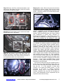
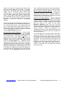
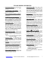
Installation / Setup Guide
Please Note: This product is Legal in California
only for racing vehicles which may never be used
upon a highway. The user shall determine suitability of the
product for his or her use. Installation and use on a pollutioncontrolled vehicle constitutes tampering under the U.S. EPA
guidelines and can lead to substantial fines. Review your
application and check your local laws before installing.
Part # 309-365 for Sportster® Models
Thank you for purchasing a ThunderMax ECM!
Please read through the following instructions before
beginning the installation procedure. Following these
instructions will ensure that the ECM is installed and
setup properly for optimal results. If you have any
problems or questions, please refer to the SmartLink
Tuning .pdf Manual, included on the CD (Help Menu)
with this package.
Step 1 Insert the SmartLink
CD into your computer.
SmartLink will automatically
open
the
InstallShield
Wizard when the computer
finds the CD-Rom. Follow
the instructions and install
the software on your
computer. If you do not have a serial port on your
computer for the communication cable, you will need to
use a USB to Serial converter (an inexpensive converter
is available from Zipper’s, #372-000). Install the included
driver disc at this time; follow the instructions given by
the manufacturer of the converter for installation.
Step 2b Unplug and remove the factory ECM from the
motorcycle (located on top of the rear fender under the
seat). Plug in and install the ThunderMax ECM in the
same location over the locating pins shown.
Step 2c Install the AutoTune module. Mount the
AutoTune module to the frame backbone using supplied
wire ties (right side view below). Position housing so
wires exit to the left as shown below.
Step 2 Install the ThunderMax and AutoTune modules.
Due to the mounting location and space constraints on
the Sportster® for the ECM, your ThunderMax system is
supplied with a separate AutoTune module.
The
ThunderMax ECM mounts in the same location as the
factory ECM under the seat; the AutoTune module must
be mounted separately.
Step 2a Remove
the seat. Open the
left
side
frame
cover (opposite the
oil tank) to expose
the fuse panel.
Locate and remove
fuse labeled “ECM
POWER” (top left
fuse; sticker with
fuse identification is
located on the inside of the frame cover).
www.Thunder-Max.com
309-365 Installation / Setup Guide V2009.04.23
[email protected]
1
Step 2d Insert AutoTune power/communication 4-pin
plug into the bike’s data port (gray), located at the base
of the battery, left side of the bike.
Step 2g Rear sensor: Route wiring down the left frame
rail behind the primary housing, with the plug located
along the frame turn. Double-back the wiring to the rear
sensor. Connect the sensor to the closed loop module,
secure with wire ties.
Oxygen Sensor Installation Notes
Step 2e Remove the factory oxygen sensors and install
the wide-band units in their place.
Step 2f Front sensor: route wiring along frame rail
(double up harness if necessary), position harness plug
at lower front primary cover area. Connect the sensor to
the closed loop module, secure with wire ties.
www.Thunder-Max.com
The wide band sensors are longer than the factory
sensors. Installation of the wide band sensors into
factory headpipes presents no clearance problems,
however, some aftermarket pipes may require exhaust
pipe modification or sensor bung relocation for
interference-free installation. The sensors must mount
freely without contacting surrounding components. If
this is not possible, do not attempt to bend or
modify the sensor in any way as it is a sensitive
electronic component and will be damaged if you do.
Modify the pipe if required for clearance. Weld-in bungs
are available for exhausts systems not equipped with
bungs or if current bungs present clearance issues.
Bungs should be located no more than 3-4” from the
head/pipe connection (for ideal location, refer to the
factory location on 2007-up models). Weld-in bungs are
available from Zipper’s (#272-200, straight; #272-202,
angled). Chase the threads after welding with an 18 x
1.5mm tap (available from auto parts stores) and verify
that the oxygen sensor threads in easily without the pipe
wall interfering with the sensor tip. After installation,
route the sensor harness away from the engine and
along the frame when possible, above the lowest frame
point to avoid the possibility of dragging ground during
operation.
Avoid routing harnesses where engine
movement or moving parts can contact and damage the
harnesses or connector plugs.
The AutoTune harness for the rear cylinder sensor is
shorter and can be easily identified by black tracers on
all of its wires; both plugs are clearly marked for front
and rear use. It is very important to install these
correctly or the engine will perform poorly! Tie the
harnesses to the frame or existing component
harnesses, taking care to avoid contact with any
vibrating component that may chaff the sheathing or
wires. Some disassembly of bike components may be
required for best harness routing.
309-365 Installation / Setup Guide V2009.04.23
[email protected]
2
Step 3 Load a Base Map to your SmartLink software.
Selecting a base map for your ThunderMax is easy
thanks to the filtering system in the SmartLink software.
Open SmartLink; from the toolbar choose [EFI Maps]
[EFI Map Listings / Definitions]. You should first
update the Map Definitions file to ensure you have the
latest available maps.
Close the [Base Map
Definitions] window, then click the [Check Internet For
Updates] button (requires internet connection; follow
prompts). After updating, select [Select BaseMap]..
Available base maps will be shown (if the [Clear Filters]
button at the lower left of the screen is highlighted, click
it to clear filtered maps so all maps will be shown).
Second, place your curser over the ‘Throttle’ column
and right click your match.
Third, right-click the ‘Exhaust’ type that closest matches
your application.
Fourth, right click the ‘Muffler’ column if further definition
of the exhaust system is required (depends on exhaust
application). Keep right-clicking the application columns
until you have located the best map match (in the case
of identical maps, choose the latest date). Highlight the
map you’ve chosen (left-click; blue bar indicates
selected map) and click [Close] button. This brings you
to the ‘Base Map Name Encoding’ page, from which you
can review the map parameters. Click the [Load
BaseMap] button to load the map into the software.
Filter the maps to locate a base map that best matches
your application by placing your curser first over any
‘Engine Type’ that matches your engine and right-click it.
All maps that do not match your selection will be filtered
from the screen.
From this page you can load the base map into the
software by clicking the [Load Base Map] button.
[Close] this page to view the open map page.
www.Thunder-Max.com
309-365 Installation / Setup Guide V2009.04.23
[email protected]
3
Step 4 From the ‘Tuning Maps’ Tree, click the + sign
next to [Module Configuration], then double-click
‘Basic Settings’. The basic settings page opens.
Check to see if the [Speedo Cal] calibration setting
matches your year and model; if not, click the button,
enter the correct value as shown, then click [Close].
Speedometer Calibration Settings
XL 883
2007-up
48400
XL 1200
2007-up
46000
Step 5 Now you are ready to ‘Link’
and ‘Write’ the map to the ECM.
Attach the communication cable
from your computer to the
ThunderMax
module,
making
certain that the cable is routed away
from any part of the motorcycle that
generates heat.
Special Note for International Model Bikes with
Active Exhaust Enabled: If your bike is equipped with
a working Active Exhaust Valve, you must unplug the
active exhaust harness before linking to the module, as
the AEV circuitry conflicts with the communication
stream. You can re-connect the harness after unlinking.
If the stock exhaust has been changed, disregard this
step. ThunderMax does not support active exhaust
Step 6 To link to the module, turn the key switch to the
“Ignition” position, making certain the “RUN / OFF”
rocker switch (Kill Switch) on the handlebar controls is in
the “RUN” position.
Select
the
“Link”
Button
in
the
SmartLink software.
The
button
turns
green to indicate a
successful link. Answer [No] to the “Do you wish to
READ the module map now” question at this time.
www.Thunder-Max.com
From the toolbar, click [File] [Write Module Maps and
Settings], answer OK to the message that informs you
that you are about to overwrite the current map in the
module; the transfer bar appears during the map load.
Step 7 Verify Module Settings. Before performing this
step, clear any active Diagnostic Code readings. While
linked, from the Tuning Tree select [Module
Configuration] [Diagnostic Codes].
When the Diagnostic Codes window appears, select
[Clear Diagnostic Codes]. After completing this step,
select Basic Settings from the Module Configuration
menu and verify that the speedometer calibration is
correct. After verifying these settings, click [Write Basic
Settings]. If the installation is to be operated in closed
loop
mode
(with
AutoTune
module),
select
[Configuration] from the toolbar menu and click
[Closed Loop Configuration]. Verify that the [Closed
Loop Processing] and [AutoTune] boxes are checked
√ on the left (module) side of the window.
IMPORTANT STEP BEFORE STARTING
Next, ‘Initialize’ the ThunderMax ECM. Initializing
synchronizes ‘home’ positions for the TPS and IAC, and
is a required step any time battery power has been
interrupted or established to the ThunderMax ECM.
With the handlebar switch in the ‘ON’ position, cycle
the key switch on and off 3 times, leaving the
ignition on for 30 seconds, then off for 30 seconds,
each cycle. DO NOT start the engine or move the
throttle during this process. After 3 on/off cycles, make
certain that the motorcycle is in neutral and start the bike
2 times, letting it settle at idle for 10 seconds; the idle
should be smooth and steady. Some engines may
require several on/off engine starts to initialize properly.
This initialization process
must be performed any time
battery power is interrupted
to the module (after battery
servicing/winterization, etc).
After initialization, shut off the
engine, but stay linked for
step 8.
309-365 Installation / Setup Guide V2009.04.23
[email protected]
4
Step 8 Before restarting the engine, from toolbar click
[Monitoring] [Show Gauges]. The “Engine Speed”,
“Engine Head Temp”, “IAC Position”, “AFR Front”, AFR
Rear” and “AFR Target” gauges are automatically
formatted and are shown on the screen. Additional
gauges can be created if desired (see SmartLink Tuning
Manual under Help menu), but the above gauges are
most helpful during initial set up. You may select any
gauges that you deem important; if too many are chosen
your screen may appear cluttered.
Step 9 Select the “Monitor” button to active the gauges.
It is located beside the “Link” button and will turn green
when the monitor gauge functions are live. The gauges
will be displayed if they were not already on the screen.
the IAC position, the engine will idle above the idle rpm
specified in the idle speed vs. engine temperature page.
If it determined that these automatic adjustments have
not resulted in satisfactory operation of the engine,
consult the SmartLink Manual (available under the Help
section of the toolbar), Section 3 (Tuning the
ThunderMax ECM) for further adjustment procedures.
CLOSED LOOP PROCESSING
When equipped with AutoTune, your SmartLink software
will allow you to set Air/Fuel tuning parameters for your
ThunderMax and its installed base map. To set the
AutoTune Limits, go to the toolbar and click [Configure]
[Close Loop MODULE Settings].
The Closed Loop Configuration dialog page opens; the
right side shows the default MAP settings stored in the
MAP file (settings are applied to the installed base map
during the ‘Closed Loop Format’ conversion performed
by SmartLink), while the left side shows what the module
is currently set to (unadjusted, these settings will mirror
Step 10 Now select the IAC Stops vs. Engine
Temperature page from “IAC Curves” menu within the
tuning
tree.
Strike
the
spacebar to show the actual values of the tuning block
(use left/right arrow keys to move the block marker).
Make certain that the motorcycle is in neutral and the
engine is cold, and then start the engine. Once the
engine idle is stable after 15- 20 seconds, select the
“IAC-Auto” button (Idle Air Control Auto Adjustment).
Allow the “IAC-Auto” function to run at idle until the
engine head temperature reaches 275 degrees. After
reaching temperature of 275 degrees, the “IAC-Auto”
function automatically shuts off. You can terminate this
function at any time, and re-run it at a later time if you
wish.
MAP’s settings).
Step 11 Unlink the SmartLink software from the ECM,
turn off the ignition switch and remove the
communication cable from the ThunderMax ECM. Use
the ‘Save As’ command to create a folder and save the
map to your hard drive. The motorcycle is now ready to
be ridden. Several riding sessions that allow the engine
to reach normal operating temperature should be
completed. During this process, the IAC virtual stops will
automatically be adjusted to the IAC target values set
within the map’s basic settings. This feature
automatically adjusts how the engine comes back to the
specified idle speed. If the IAC stops are set too low, the
engine will dip below the specified idle speed during
certain transient conditions. If the IAC stops are above
www.Thunder-Max.com
The un-highlighted left ‘MODULE’ side of the page
allows editing of those settings within the MODULE for
tuning purposes, while unaffecting the MAP settings. To
edit module settings, click the [Link/Read (Module)]
button (left side highlights/active). You can now edit
these settings within the live module should you want to
change any of the settings from the MAP default
settings.
Closed Loop Processing (Module) – Check [ON] to
enable closed loop AutoTune processing. During closed
loop processing, the ThunderMax module processes
feedback from the oxygen sensors to adjust the fuel
309-365 Installation / Setup Guide V2009.04.23
[email protected]
5
volume at all points by creating learned “offset” points
from the installed ‘base map’ fuel points. The ‘static’
base map is dynamically used by the ThunderMax
module and the AutoTune’s active (closed loop)
feedback system. This system optimizes the fuel points
to fit the target air/fuel ratio through ‘learned offset
points’. These ‘learned offset points’ are stored within
the ThunderMax and are used in conjunction with the
base map. The ‘base map’ fuel points are not being
adjusted by either the AutoTune or ThunderMax
modules.
If AutoTune Closed Loop Processing is un-checked, fuel
points will be adjusted to the last learned offset points, or
if no learning has occurred, to the original base map
points. Stored offset points remain within the module; in
the event that power is interrupted for any reason, the
learned offset points remain until re-learned or cleared
under the [Map Editing] toolbar menu.
Air Fuel Ratio Override (Module) – A single Target
AFR setting can be applied using this command.
Clicking this box and changing this number overrides
ALL ‘Air/Fuel Ratio vs. TPS’ pages at all RPM’s. To
target specific Air/Fuel Ratio RPM ranges and throttle
positions, leave this box unchecked and edit the
individual ‘Air/Fuel-TPS @ RPM’ map pages located
under the [Tuning Maps] tree. Individual Air/Fuel
targets are pre-set within the base map to provide a
good balance between power and economy. Individual
cell throttle position/rpm AFR targets can be viewed and
adjusted on these pages. Use the left/right arrow keys
to navigate the individual blocks (strike the spacebar to
view the values); use the up/down arrow keys to adjust
the values. Click the [Monitor] button when linked live
www.Thunder-Max.com
and a vertical bar will show the actual throttle position.
See the SmartLink manual for further tuning instructions.
Idle Air Control Override (Module) - Check [OFF].
This setting should not be checked on except for
diagnosing a particular type of supported problem or
during tuning on a load cell dyno. Changing this setting
will lead to starting and idling problems.
Maximum CLP Offset (Module) – [Session (Module)]
button sets the AFR maximum learning correction from
the base map’s fuel setting per session by percentage
(range is 0-10%). A ‘session’ is defined as the period of
time from engine on to engine off (per cycle).
[Maximum (Module)] button sets the total AFR
maximum learning correction from the base map’s fuel
setting by percentage (regardless of number of sessions;
range is 0-25%).
Unless your application is a
considerable mismatch to the installed base map, the
default settings of 5 and 20 percent are sufficient for
most AFR corrections.
You should always pick the best possible map match
during the selection of your base map. The theory
behind this is to reduce the range and time the closed
loop system needs to learn offsets (corrections) for the
target AFR. If your map selection is a poor match to the
application, the amount of learning needed will be
significant. Review the parameters of your base map vs.
available base maps under ‘Base Maps Listing’ to
ensure you have the best map match and the latest
version of the map.
309-365 Installation / Setup Guide V2009.04.23
[email protected]
6
TIPS AND GENERAL INFORMATION
•
Several support features are located under the
[Help] menu; some require an internet
connection.
•
A comprehensive Tuning Manual in PDF
format is included on the CD for viewing and
printing from your desktop.
•
When the SmartLink program is opened, it
will automatically retrieve and open the last map
that was open.
•
Any time you link to your motorcycle: Read
the map that is installed in the ThunderMax
ECM by selecting [File] then [Read Module
Maps and Settings] on the SmartLink toolbar.
This will synchronize the map file loaded into the
ThunderMax ECM with the SmartLink software.
•
•
•
2003 FLT/FLHT models: H-D® used 2 different
speedometer calibrations during the extended
2003 model production. Which calibration you
may need is easily identified by checking the
part number on the back of your factory ECM.
Calibration 20480 is used if the part number
ends in -03, while 4352 is used if the ECM p/n
ends in -02. If your turn signals don’t cancel on
a 2003 model, try the alternate setting.
2007-up Big Twin models: There are two
settings in the [Module Configuration] [Basic
Settings] page that should to be set to the
following to enable the 6th gear indicator light to
function:
Final drive ratio [87; 84 for 06-07 Dyna®]
Gear 6 Min TPS [40].
Sportster® models: The [Main Relay Loc]
must be set to “1” under the [Basic Settings]
[Module Configuration] page, or the engine will
not start.
•
Accel Fuel is be used to tune throttle response
(go to [Module Configuration] [Basic Settings]).
•
AFR Correction vs. Engine Temperature page
is used to adjust cold start AFR’s. It is active yet
should be used with extreme caution. Any
changes made to this page affects all maps, at
every throttle position, every 256 RPM’s! See
SmartLink Tuning Manual for procedures.
•
AFR vs. Engine Temperature is active yet at
this time you should be discouraged from
making any changes to this page.
www.Thunder-Max.com
Installation / Setup Guide V2009-04.23
•
Air/Fuel-TPS @ RPM These pages reflect
desired targets of AFR to throttle position at
every 256 RPM. Example: if you desire a leaner
mixture for added fuel economy then you can
easily make multi-tiered AFR targets at specific
throttle positions and RPM’s that will be learned
during closed loop processing.
•
During warm-up, the AFR on both cylinders will
be richer than the target AFR at normal
operating temperatures; this is a normal part of
the warm-up map. AutoTune and its targets are
inactive below 200 degrees.
•
Target air/fuel ratios can be viewed on the
Air/Fuel-TPS @ RPM pages.
When these
pages are open, you can view the target AFR by
clicking on a dot and tapping the space bar to
view the target at a specific throttle position for
that RPM. Use arrow keys to raise/lower targets.
•
Writing new or modified maps to the module
requires the system to be re-initialized (Step 7),
and any existing learned fuel and IAC
adjustments to be cleared (Map Editing, clear).
Linking and editing an existing map within the
module does not require above steps.
•
System Updates are available through
SmartLink with an internet connection.
Software, Firmware and Map updates can be
downloaded; check frequently for updates.
•
In-Tank Fuel Filters should be inspected as a
part of routine maintenance. The filter is small
and one bad load of fuel can clog it. The factory
recommended service interval is 25K miles.
•
Save your edited maps to your hard drive
using the [Save As] command. Document the
changes in [Map Notes] located under [EFI
Maps on the toolbar. These notes are stored
with the saved map; remember to edit them
when making changes for future reference.
•
Oxygen Sensor Care: Items that can damage
or shorten the life of your sensors:
Leaded fuel – Race fuel
Oil deposits from oil consumption problems
Excessive moisture exposure
Excessive (extreme) heat
There is no warranty on sensors. Replacement
P/N is 309-355.
[email protected]
7