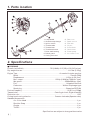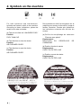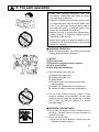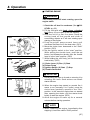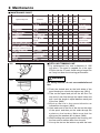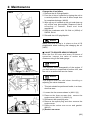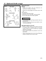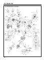
1
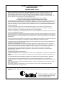
T3032-93110 (004) OWNER / OPERATOR MANUAL BRUSHCUTTERS BCX2600S WARNING WARNING The engine exhaust from this product contains chemicals known to the State of California to cause cancer, birth defects or other reproductive harm. Before using our brushcutters, please read this manual carefully to understand the proper use of your unit. APPLICABLE SERIAL NUMBERS : DRIVE UNIT 900101 and up ENGINE UNIT 900101 and up SAFETY FIRST Instructions contained in warnings within this manual marked with a symbol concern critical points which must be taken into consideration to prevent possible serious bodily injury, and for this reason you are requested to read all such instructions carefully and follow them without fail. ■ WARNINGS IN THE MANUAL WARNING This mark indicates instructions which must be followed in order to prevent accidents which could lead to serious bodily injury or death. IMPORTANT This mark indicates instructions which must be followed, or it leads to mechanical failure, breakdown, or damage. NOTE This mark indicates hints or directions useful in the use of the product. 1. 2. 3. 4. 5. 6. 7. 8. 9. 10. 11. 12. 13. CONTENTS Parts location …………………………………4 Specifications …………………………………4 Warning labels on the machine ……………5 Symbols on the machine ……………………6 For safe operation ……………………………7 Set up …………………………………………13 Oil / Fuel………………………………………15 Operation ……………………………………17 Maintenance …………………………………20 Cleaning and storage ………………………28 Optional blade usage ………………………29 Troubleshooting guide ………………………34 Parts list ………………………………………35 1. Parts location 1. 2. 3. 4. 5. 6. 7. 8. 9. Loop handle Shoulder strap hanger Ignition switch Throttle cable Throttle lever Throttle set button Drive shaft housing Debris guard Cutting line head 10. 11. 12. 13. 14. 15. 16. 17. Gear case Spark arrester Fuel tank Oil port Starter knob Choke lever Primer pump Air cleaner cover 2. Specifications ■ BCX2600S Overall size(LxWxH)······················································ 72.5(1840)x12.5(320)x13.6(345) in(mm) Dry weight w/o acc.····························································································· 11.6 lbs (5.25kg) Engine Type······················································································ Air-cooled 4-stroke gasoline Model··········································································································· Zenoah F26A Displacement ····················································································· 1.65cu-in (26.2cm3) Max. output ································································· 1.05Hp (0.8kW)at 7500/min-1(rpm) Idle speed··························································································3200±200/min-1(rpm) Fuel····································································································· Unleaded Gasoline Carburetor ··················································································· Walbro Diaphragm type Spark plug···························································································Champion RDZ19H Fuel tank capacity·······························································································20.0 fl.oz (0.59 ) Transmission··········································································· Centrifugal clutch, Rigid driveshaft Reduction ratio ····················································································································· 1.357 Cutting head rotating direction ················································ Counter-clockwise(Operator view) Standard Accessories 4 in. 2-line Head ········································································································ 1 pc. Shoulder Strap ·········································································································· 1 pc. Goggle ······················································································································· 1 pc. Tool Kit ······················································································································ 1 pc. Specifications are subject to change without notice. 4 3. Warning labels on the machine (1) Read owner's manual before operating this machine. (2) Wear head, eye and ear protection. (3) Warning/Attention (4) Keep all children, bystanders and helpers 15 meters away from the brushcutter IMPORTANT If warning label peel off or become soiled and impossible to read, you should contact the dealer from which you purchased the product to order new labels and affix them in the required location(s). WARNING Never modify your brushcutter. We won't warrant the machine, if you use the remodeled brushcutter or you don't observe the proper usage written in the manual. (1) Lire le mode d’emploi avant d’utiliser cette machine. (2) Porter un casque de sécurité, des lunettes de sécurité et un casque antibruit. (3) Avertissement/Attention (4) Interdire aux enfants ou à toute personne de s’approcher dans un rayon de 15 mètres de la débroussailleuse. IMPORTANT Si les étiquettes d’avertissement se décollent, deviennent sales ou impossible à lire, commander de nouvelles étiquettes auprès du revendeur pour les remplacer. AVERTISSEMENT Ne pas modifier la débroussailleuse. La garantie sera annulée si la débroussailleuse a été modifiée ou utilisée de manière non conforme aux instructions de ce mode d’emploi. 5 4. Symbols on the machine For safe operation and maintenance, symbols are carved in relief on the machine. According to these indications, please be careful not to take a mistake. (a) The port to refuel the “UNLEADED FUEL” Position: FUEL TANK CAP (b) The direction to close the choke Position: AIR CLEANER COVER (c) The direction to open the choke Position: AIR CLEANER COVER Des symboles en relief ont été placés sur la machine pour assurer la sécurité à l’usage et faciliter l’entretien. Prendre soin d’observer les indications suivantes afin d’éviter les erreurs. (a) Orifice de remplissage du carburant “Essence sans plomb” Emplacement : BOUCHON DU RESERVOIR DE CARBURANT (b) Position fermée du starter Emplacement: CAPOT DU FILTRE A AIR (c) Position ouverte du starter Emplacement: CAPOT DU FILTRE A AIR IMPORTANT ENGINE INFORMATION THIS ENGINE MEETS U.S. EPA PH1 AND 2000 AND LATER CALIFORNIA EMISSION REGULATIONS FOR SMALL OFF-ROAD ENGINES WITH AN EMISSION DURABILITY PERIOD OF 300 HOURS. ENGINE FAMILY : XKZXS.0264YZ;EM ENGINE DISPLACEMENT : 26.2cc REFER TO OWNER’S MANUAL FOR MAINTENANCE SPECIFICATIONS AND ADJUSTMENTS. 6 INFORMATION IMPORTANTE CONCERNANT LE MOTEUR Ce moteur est conformc aux normcs U.S. EPA PH1 et 2000 ainsi qu’aux autres dispositions ultérieures de la réglementation concernant la pollution de l’air pour les petits moteurs tout-terrain avec une période de durabilité opour les émissions de 300 heures. Type de moteur : XKZXS.0264YZ;EM Cylindrée du moteur : 26,2cc Se référer au Manuel de l’utilisateur pour les spécifications d’entretien et les réglages. 5. For safe operation 1. Read this manual carefully until you completely understand and follow all safety and operating instructions. 2. Keep this manual handy so that you may refer to it later whenever any questions arise. Also note, if you have any questions which cannot be answered herein, contact the dealer from whom you purchased the product. 3. Always be sure to include this manual when selling, lending, or otherwise transferring the ownership of this product. 4. Never allow children or anyone unable to fully understand the directions given in the manual to use the machine. ■ WORKING CONDITION 1. When using the product, you should wear proper clothing and protective equipment. (1) Helmet (2) Ear protectors (3) Protection goggles or face protector (4) Thick work gloves (5) Non-slip-sole work boots 2. And you should carry with you. (1) Attached tools and files (2) Properly reserved fuel (3) Spare blade (4) Things to notify your working area (rope, warning signs) (5) Whistle (for collaboration or emergency) (6) Hatchet or saw (for removal of obstacles) 3. Do not wear loose clothing, jewelry, short trousers, sandals, or go barefoot. Do not wear anything which might be caught by a moving part of the unit. Secure hair so it is above shoulder length. ■ WORKING CIRCUMSTANCE 1. Never start the engine inside a closed room or building. Exhaust gases contain dangerous carbon monoxide. 2. Never use the product, a. when the ground is slippery or when you can’t maintain a steady posture. 7 5. For safe operation b. At night, at times of heavy fog, or at any other times when your field of vision might be limited and it would be difficult to gain a clear view of the working area. c. During rain storms, during lightning storms, at times of strong or gale-force winds, or at any other times when weather conditions might make it unsafe to use the product. ■ WORKING PLAN 1. You should never use the product when under the influence of alcohol, when suffering from exhaustion or lack of sleep, when suffering from drowsiness as a result of having taken cold medicine or at any other time when a possibility exists that your judgment might be impaired or that you might not be able to operate the product properly and in a safe manner. 2. When planning your work schedule, allow plenty of time to rest. Limit the amount of time over which the product is to be used continuously to somewhere around 30~40 minutes per session, and take 10~20 minutes of rest between work sessions. Also try to keep the total amount of work performed in a single day under 2 hours or less. WARNING 1. If you don’t observe the working time, or working manner (See ■ USING THE PRODUCT), Repetitive Stress Injury(RSI) could occur. If you feel discomfort, redness and swelling of your fingers or any other part of your body, see a doctor before getting worse. 2. To avoid noise complaints, in general, operate product between 8a.m. and 5p.m. on weekdays and 9a.m. to 5p.m. weekends. NOTE Check and follow the local regulations as to sound level and hours of operations for the product. 8 5. For safe operation ■ BEFORE STARTING THE ENGINE 1. The area within a perimeter of 50 feet (15m) of the person using the product should be considered a hazardous area into which no one should enter. If necessary yellow warning rope, warning signs should be placed around the perimeter of the area. When work is to be performed simultaneously by two or more persons, care should also be taken to constantly look around or otherwise check for the presence and locations of other people working so as to maintain a distance between each person sufficient to ensure safety. 2. Check the condition of working area to avoid any accident by hitting hidden obstacles such as stumps, stones, cans, or broken grass. IMPORTANT Remove any obstacle before beginning work. 3. Inspect the entire unit for loose fasteners and fuel leakage. Make sure that the cutting attachment is properly installed and securely fastened. 4. Be sure the debris guard is firmly attached in place. 5. Always use the shoulder strap. Adjust the strap for comfort before starting the engine. The strap should be adjusted so the left hand can comfortably hold the handlebar grip approximately waist high. ■ STARTING THE ENGINE 1. Keep bystanders and animals at least 50 feet (15m) away from the operating point. If you are approached, immediately stop the engine. 2. The product is equipped with a centrifugal clutch mechanism, so the cutting attachment begins to rotate as soon as the engine is started by putting the throttle into the start position. When starting the engine, place the product onto the ground in a flat clear area and hold it firmly in place so as to ensure that neither the cutting part nor the throttle come into contact with any obstacle when the engine starts. 9 5. For safe operation WARNING Never place the throttle into the high speed position when starting the engine. 3. After starting the engine, check to make sure that the cutting attachment stops rotating when the throttle is moved fully back to its original position. If it continues to rotate even after the throttle has been moved fully back, turn off the engine and take the unit to your authorized Red Max servicing dealer for repair. ■ USING THE PRODUCT IMPORTANT Cut only materials recommended by the manufacturer. And use only for tasks explained in the manual. 1. Grip the handles firmly with both hands using your whole hand. Place your feet slightly apart (slightly further apart than the width of your shoulders) so that your weight is distributed evenly across both legs, and always be sure to maintain a steady, even posture while working. 2. Keep cutting attachment below waist level. 3. Maintain the speed of the engine at the level required to perform cutting work, and never raise the speed of the engine above the level necessary. 4. If the unit start to shake or vibrate, turn off the engine and check the whole unit. Do not use it until the trouble has been properly corrected. 5. Keep all parts of your body away from rotating cutting attachment and hot surfaces. 6. Never touch the muffler, spark plug, or other metallic parts of the engine while the engine is in operation or immediately after shutting down the engine. Doing so could result in serious burns or electrical shock. 10 5. For safe operation • IF SOMEONE COMES 1. Guard against hazardous situations at all times. Warn adults to keep pets and children away from the area. Be careful if you are approached. Injury may result from flying debris. 2. If someone calls out or otherwise interrupts you while working, always be sure to turn off the engine before turning around. ■ MAINTENANCE 1. In order to maintain your product in proper working order, perform the maintenance and checking operations described in the manual at regular intervals. 2. Always be sure to turn off the engine before performing any maintenance or checking procedures. WARNING The metallic parts reach high temperatures immediately after stopping the engine. 3. When replacing the cutting attachment or any other part, or when replacing the oil or any lubricant, always be sure to use only RedMax products or products which have been certified by RedMax for use with the RedMax product. 4. In the event that any part must be replaced or any maintenance or repair work not described in this manual must be performed, please contact a representative from the store nearest RedMax authorized servicing dealer for assistance. 5. Do not use any accessory or attachment other than those bearing the RedMax mark and recommended for the unit. 6. Under no circumstances should you ever take apart the product or alter it in any way. Doing so might result in the product becoming damaged during operation or the product becoming unable to operate properly. ■ HANDLING FUEL 1. The engine of the RedMax product is designed to run on a raw fuel which is highly flammable gasoline. Never store cans of fuel or refill the 11 5. For safe operation tank of the unit in any place where there is a boiler, stove, wood fire, electrical sparks, welding sparks, or any other source of heat or fire which might ignite the fuel. 2. Never smoke while operating the unit or refilling its fuel tank. 3. When refilling the tank, always turn off the engine and allow it to cool down. Take a careful look around to make sure that there are no sparks or open flames anywhere nearby before refueling. 4. Wipe spilled fuel completely using a dry rag if any fuel spillage occurs during refueling. 5. After refueling, screw the fuel cap back tightly onto the fuel tank and then carry the unit to a spot 10 feet or more away from where it was refueled before turning on the engine. ■ TRANSPORTATION 1. When hand-carrying the product, cover over the cutting part if necessary, lift up the unit and carry it paying attention to the cutting part. 2. Never transport the product over rough roads over long distances by vehicle without removing all fuel from the fuel tank. If doing so, fuel might leak from the tank during transport. 12 6. Set up ■ MOUNTING ENGINE (SE1) 1. Push the driveshaft housing toward the clutch housing and rotate it by hand to check that the driveshaft is engaged with the gears. 2. Insert the driveshaft housing into the clutch housing until it bottoms, and align the positioning holes on the clutch housing and the shaft tube and install the screw. When difficult to engage, twist the engine slightly. 3. Fasten the clamp securely with two screws. SE1 SE2 IMPORTANT Tighten the screws gradually by turns. ■ CONNECTING THROTTLE WIRE 1. Remove the air cleaner cover. 2. Connect the end of the throttle wire to the joint on the top of the carburetor. (SE2) ■ CONNECTING SWITCH WIRES • Connect the switch wires between the engine and the main unit. Connect the wire to the same color receiver on the main unit. SE3 ■ INSTALLING HANDLE • Mount the handle to the shaft tube and clamp it at a location that is comfortable to you. (SE3) (1) (1) About 19 inches (48cm) ■ INSTALLING DEBRIS GUARD • Put the debris guard on the gear box, attach it with the 4 screws and hardware provided. (SE4) SE4 (1) (1) Debris Guard (2) Plate (3) Screw (2) (3) 13 6. Set up SE5 SE6 14 ■ INSTALLING CUTTING HEAD (SE5) 1. While locking the gear shaft, by inserting the supplied tool into the upper holder on the gear box, loosen and remove the hexagon nut(lefthanded) 2. Fit the holder attached to the upper holder. Then screw in the cutting head to the gear shaft over the holders. Hand-tighten it securely. ■ BALANCE UNIT 1. Put on strap and attach unit to strap. 2. Slide clamp up or down until unit balances with head just touching on the ground. (SE6) 7. Oil / Fuel ■ RECOMMENDED OIL TYPE Using the proper type and weight of oil in the crankcase is extremely important. Check the oil before each use and change the oil regularly. Failure to use the correct oil, or using dirty oil, can cause premature engine wear and failure. Use a high-quality SAE30 weight oil of API (American Petroleum Institute) service class SH. ■ ADDING OIL TO CRANKCASE-INITIAL USE 1. Install the funnel spout. 2. Place the unit on a flat lever surface. 3. Remove the oil plug/dipstick from the crankcase. Pour 3.4 fl oz(100ml) oil into the crankcase. up to the : top of the dipstick NOTE Never add oil to the fuel or fuel tank. 4. Wipe up any oil that may have spilled and reinstall the oil fill plug/dipstick. The importance of checking and maintaining the proper oil level in the crankcase cannot be overemphasized. Check oil before each use and change as needed as shown in Maintenance section. ■ RECOMMENDED FUEL TYPE WARNING Gasoline is extremely flammable and its vapors can explode if they if they are ignited. To avoid serious personal injury, always stop the engine and allow it to cool before filling the fuel tank. Do not smoke while filling the tank. Keep sparks and open flames away from the area. WARNING Pressure can build up in the fuel tank. Loosen the fuel tank cap slowly to relieve any pressure in the tank. 15 7. Oil / Fuel Old fuel is usually the main reason for the unit not running properly. Be sure to use fresh, clean, unleaded fuel. NOTE Alcohol-blended fuel absorbs moisture (water). As little as 1% moisture in the fuel can cause it to separate and form acids when stored. If this type of fuel must be used, use fresh fuel (less than 60 days old). ■ DEFINITION OF BLENDED FUELS Today's fuels are often a blend of gasoline and one or more oxygenates such as ethanol, methanol or MTBE (ether). ■ USE OF BLENDED FUELS If you choose to use a blended fuel or its use is unavoidable, the following precautions are recommended. 1. Always use fresh unleaded fuel per your operator's manual. 2. Use the special additive STA-BIL® or an equivalent. 3. Always agitate the fuel mix before fueling the unit. 4. Drain the tank and run the engine dry before storing the unit. ■ USE OF FUEL ADDITIVES The use of fuel additive, such as STA-BIL® Gas Stabilizer or an equivalent, will inhibit corrosion and minimize the formation of gum deposits. Add 0.8oz (23ml) per gallon of fuel per instructions on container. NEVER add fuel additives directly to the unit's fuel tank. Using a fuel additive can keep fuel fresh for up to six(6) months. 16 8. Operation ■ STARTING ENGINE WARNING The cutting head will start rotating upon the engine starts. 1. Check the oil level in crankcase (See ■ OIL LEVEL at p.22). 2. Fill the fuel tank with fresh, clean, unleaded fuel (See p.16) up to 80% of the full capacity. 3. Rest the unit on a flat, firm place. Keep the cutting head off the ground and clear of surrounding objects as it will start rotating upon starting of the engine. 4. Push the primer pump several times until overflown fuel flows out in the clear tube. (OP1) 5. Move the choke lever downward to the “Start” position. (OP1) 6. Set the ignition switch to the “start” position. While pulling the throttle lever, push the set button, and release the throttle, then the throttle lever is in the “start” position. (OP2) 7. While holding the unit firmly, pull out the starter knob briskly. (OP3) (1) Choke Lever (2) Run (3) Start (4) Primer Pump (5) Ignition Switch (6) Start (7) Stop (8) Throttle Set Button OP1 OP2 (6) (7) (5) (8) OP3 IMPORTANT • Avoid pulling the rope to its end or returning it by releasing the knob. Such actions can cause starter failures. 8. When the engine has started or sounds like it wants to run (normally 2 to 5 pulls), move the choke lever gradually upword to the “Run” position. In the case the engine has not started after opening the choke, pull the starter knob briskly to start the engine. (OP3) 9. Allow the engine to warm up for a several minutes before starting operation. NOTE 1. When restarting the engine immediately after stopping it, leave the choke “RUN” position. 17 8. Operation 2. Overchoking can make the engine hard to start due to excess fuel. When the engine failed to start after several attempts, open the choke and repeat pulling the rope, or remove the spark plug and dry it. ■ STOPPING ENGINE (OP2) 1. Release the throttle lever and run the engine for a half minute. 2. Shift the ignition switch to the STOP position. IMPORTANT • Except for an emergency, avoid stopping the engine while pulling the throttle lever. ■ ADJUSTING IDLING SPEED (OP4) 1. When the engine tends stop frequently at idling mode, turn the adjusting screw clockwise. 2. When the cutting head keeps rotating after releasing the trigger, turn the adjusting screw counter-clockwise. (1) Idle Adjusting Screw OP4 NOTE IDLE SPEED: 3200rpm OP5 (1) 0.04~0.08 inch (1~2mm) • Warm up the engine before adjusting the idling speed. ■ ADJUSTING THE WIRE PLAY (OP5) 1. Place the throttle lever to the fully returned position. 2. Pull the throttle cable and check the play is proper range (0.04~0.08in)(1~2mm). 3. If the play is too large, bend the wire bracket to left side (i.e. cable side) by plier etc. And if the play is too small, bend the wire bracket to right side (i.e. carburetor side) by plier etc. (1) Wire bracket IMPORTANT • Too large play causes wire out from the position. Too small play causes throttle lever does not stay at idling position. 18 8. Operation ■ CUTTING WORK (LINE HEAD USAGE) WARNING 1. Always wear eye protection such as safety goggles. Never lean over the rotating cutting head. Rocks or other debris could be thrown into eyes and face and cause serious personal injury. 2. Keep the debris guard in place at all times when the unit is operated. OP6 TRIMMING GRASS AND WEEDS • Always remember that the TIP of the line does cutting. You will achieve better results by not crowding the line into the cutting area. Allow the unit to trim at its own pace. 1. Hold the unit so the head is off the ground and is tilted about 20 degrees toward the sweep direction. (OP6) 2. You can avoid thrown debris by sweeping from your left to the right. 3. Use a slow, deliberate action to cut heavy growth. The rate of cutting motion will depend on the material being cut. Heavy growth will require slower action than will light growth. 4. Never swing the unit so hard as you are in danger of losing your balance or control of the unit. 5. Try to control the cutting motion with the hip rather than placing the full workload on the arm and hands. 6. Take precautions to avoid wire, grass and dead, dry, long-stem weeds from wrapping around the head shaft. Such materials can stall the head and cause the clutch to slip, resulting in damage to the clutch system if repeated frequently. ADJUSTING THE LINE LENGTH • Your brushcutters is equipped with a semi- auto type nylon line head that allows the operator to advance the line without stopping the engine. When the line becomes short, lightly tap the head on the ground while running the engine at full throttle. • Each time the head is bumped, the line advance about 1 inch(25.4 mm). For better effect, tap the head on bear ground or hard soil. Avoid bumping in thick, tall grass as the engine may stall by overload. 19 9. Maintenance ■ MAINTENANCE CHART system/compornent SHAFT ENGINE oil level oil fuel filter, air filter fuel tank fuel leaks, fuel spillage idle adjusting screw procedure check/add oil, if needed change oil check/clean clean/fill the correct fuel wipe out see ■adjusting idling speed(p.18) spark plug clean and readjust plug gap the valve to rocker arm clearance check/clean cylinder fins, intake air cooling vent clean muffler, spark arrester, cylinder clean exhaust port, combustion chamber throttle lever, ignition switch check operation cutting parts replace if something’s wrong debris guard make sure to attach gear case grease screws/nuts/bolts tighten/replace MA1 MA2 first first every every every 10 20 25 50 100 before hours hours hours hours hours note use after after after after after ✔ ✔ ✔ recheck before longterm storage ✔ ✔ replace if needed ✔ ✔ ✔ replace, carburetor if needed ✔ GAP: .025in(0.655mm) replace if needed ✔ ✔ adjust, if necessary ✔ ✔ ✔ ✔ ✔ ✔ ✔ ✔ not adjusting screws ■ REFILLING TRIMMING LINE 1. For replacement line, use a diameter of .095 in(2.4mm). The spool is capable for a line upto 27ft(8 m)on the 4” head. Avoid using a larger line as it may cut down the trimming performance. WARNING For safety reasons, do not use metalreinforced line. MA3 MA4 20 2. Pinch the slotted area on the both sides of the spool housing to unhook the bottom cap. (MA1) 3. Take out the spool and pull off the old line. Put one end of new line through the spool holes and pull it until the length is equal between each part of the line. (MA2) 4. Wind up the line in the correct direction as indicated on the spool. (MA3) 5. Hook each end of the line in the slot on the edge of the spool, and then put the ends through the eyelets on the housing. Make sure that the spring and the washers are in place. (MA4) 6. While holding the spool against the housing, pull the line ends to release them from the slot. 7. Line up the slot on the bottom cap with the hook 9. Maintenance on the housing, press the cap against the housing until it clicks. WARNING • Make sure that the engine has stopped and is cool before performing any service to the machine. Contact with moving cutting head or hot muffler may result in a personal injury. MA5 ■ AIR FILTER IMPORTANT Your unit's air filter is one of the most important areas to maintain. If it is not maintained, you will void the warranty. MA6 MA7 1. Remove the air filter cover by pulling up the two tabs on the bottom back of the cover, then pull out and up. (MA5) 2. Remove the air the filter. (MA5) 3. Wash the filter in detergent and water. Rinse the filler thoroughly and allow it to dry. (MA6) 4. Reinstall the filter. (MA5) 5. Reinstall the air filter cover by positioning the notch on top of the air filter cover onto the tab at the top of the back plate. (MA7) 6. Using two fingers on either side of the air filter cover and back plate, squeeze together until the cover snaps into place. (MA7) (1) Air Filter Cover (2) Air Filter (3) Choke Lever (4) Tab (5) Back Plate WARNING Never operate the machine without air filter or filter cover. Doing so could lead the engine breakdown. 21 9. Maintenance ■ OIL LEVEL WARNING To prevent extensive engine wear and damage to the unit, always maintain the proper oil level in the crankcase. Never operate the unit with the oil level below the bottom of the dipstick. MA8 MA9 1. Make sure the engine is stopped and is cool so the oil has had times to drain into the crankcase. 2. Place the unit on a flat, level surface to get a proper oil level reading. 3. To keep dirt, grass clippings, etc., out of the engine, clean the area around the oil fill plug/dipstick before removing it. 4. Remove the oil plug/dipstick and wipe the oil off. Reinsert it all the way back in. 5. Remove the oil plug/dipstick and check the oil level. The level should be up to the top of the dipstick. (MA9) 6. If the level is low, add a small amount of oil to the crankcase and recheck. Continue to do this until the oil level reaches the top of the dipstick. (MA9) (1) Oil Fill Plug/Dipstick (2) O-Ring (3) Top of Dipstick NOTE Be careful not to overfill the unit. CHANGING THE OIL For a new engine, change the oil after the first 10 hours of operation. Thereafter, change the oil after every 50 hours or before storing the unit for an extended period of time. It is best to change the oil while the engine is still warm. The oil will flow freely and carry away more impurities. WARNING Wear gloves to prevent injury when handing the unit. 22 9. Maintenance MA10 Change the oil as follow: 1. Remove the oil fill plug/dipstick. 2. Pour the oil into a container by tipping the unit to a vertical position. Be sure to allow ample time for complete drainage. (MA10) 3. Wipe up any oil residue on the unit and clean up any oil that may have spilled. Dispose of the oil according to Federal, State and local regulations. 4. Refill the crankcase with 3.4 fluid oz (100ml) of SAE30, SH oil. 5. Reinstall the oil fill plug/dipstick. NOTE Make sure the O-ring is in place on the oil fill plug/dipstick when checking and changing the oil. (MA9) MA11 ■ VALVE TO ROCKER ARM CLEARANCE After the first 20 hours and every 50 hours of operation, inspect the valve to rocker arm clearance using a flat feeler gauge. NOTE This requires some disassembly of the engine. If you feel unsure or unqualified to perform this, take the unit to an authorized service center. MA12 NOTE The engine must be cold when checking or adjusting the valve clearance. • This task should be performed inside, in a clean, dust free area. MA13 1. Loosen the four screws shown in (MA11 (2)). 2. Remove the three screws that secure the engine cover. (MA11 (1), MA12 (1)) 3. Disconnect the spark plug wire. 4. Remove the spark plug and then remove the engine cover. 5. Remove the rocker arm cover and gasket. (MA13) (1) Rocker arm cover 23 9. Maintenance 6. While looking in the spark plug hole, pull the starter rope slowly and bring the piston to the top position. Check that both rocker arms should move freely. If they do not, repeat this step. This will be top of the compression stroke. 7. Using a flat feeler gauge, measure the clearance between the valve stems and rocker arms. (MA14) (1) Feeler gauge (2) Rocker arm (3) Adjusting nut (4) Gasket MA14 The recommended clearance for both intake and exhaust is .003~.006in, (0.076~0.152mm). The feeler gauge should side between the rocker arm and valve stem with a slight amount of resistance, without binding. 8. If the clearance is not within specification, adjust as follows: a. Turn the adjusting nut using a 5/16 inch (8mm) wrench or nut driver.(MA14) To increase the clearance, turn the adjusting nut counterclockwise. To decrease the clearance, turn the adjusting nut clockwise. b. Recheck both valve clearances and adjust as necessary. 9. Reinstall the rocker arm cover using a new gasket. Torque the screw to 37~43 in-lbs (4.1~4.7 N.m.). 10.Reinstall the engine cover. Check alignment of the cover before tightening the screws. Be sure to tighten the screws loosened in step 1. 11.Check the plug, see Replacing the Spark Plug, and reinstall. Torque the spark plug to 100~110 in-lbs (11.3~12.3 N.m.). Reinstall the spark plug wire. MA15 ■ FUEL FILTER • When the engine runs short of fuel supply, check the fuel cap and the fuel filter for blockage. (MA15) (1) Fuel filter (1) 24 9. Maintenance ■ SPARK PLUG IMPORTANT • Starting failure and mis-firing are often caused by a fouled spark plug. Clean the spark plug and check that the plug gap is in the correct range. For a replacement plug, use the correct type specified by RedMax. (MA16) Specified plug is Champion RDZ19H MA16 .025 in 0.655mm 1. Stop the engine and allow it to cool. Pull the wire off of the spark plug. 2. Clean around the spark plug and remove it from the cylinder head. Use a 5/8 inch (16mm) socket to remove the plug. 3. Clean the electrode. 4. Set the plug gap at 0.025 in. (0.655mm) using a feeler gauge (MA16). Install a correctly gapped spark plug into the cylinder head. • To install the spark plug, first turn the plug until it is finger tight, then tighten it a quarter turn more with a socket wrench. TIGHTENING TORQUE: 100~110 in-lbs (11.3~12.3 N.m.) ■ MUFFLER WARNING • Inspect periodically, the muffler for loose fasteners, any damage or corrosion. If any sign of exhaust leakage is found, stop using the machine and have it repaired immediately. • Note that failing to do so may result in the engine catching on fire. 25 9. Maintenance MA17 (1) MA18 ■ SPARK ARRESTER • The muffler is equipped with a spark arrester to prevent red hot carbon from flying out of the exhaust outlet. Periodically inspect and clean as necessary with a wire brush. In the State of California it is required by law (Section 4442 of the California Public Resources Code) to equip a spark arrester when a gas powered tool is used in any forest covered, brush covered, or grass covered unimproved land. (MA17) (1) spark arrester ■ GEAR CASE (MA18) • The reduction gears are lubricated by multipurpose, lithium-based grease in the gear case. Supply new grease every 25 hours of use or more often depending on the job condition. • Remove the cutter holders before installing new grease to arrange for old grease to exit. ■ INTAKE AIR COOLING VENT WARNING • Never touch the cylinder, muffler, or spark plugs with your bare hands immediately after stopping the engine. The engine can become very hot when in operation, and doing so could result in severe burns. • When checking the machine to make sure that it is okay before using it, check the area around the muffler and remove any wood chips or leaves which have attached themselves to the brushcutter. Failing to do so could cause the muffler to become overheated, and that this in turn could cause the engine to catch on fire. Always make sure that the muffler is clean and free of wood chips, leaves, and other waste before use. • Check the intake air cooling vent and the area around the cylinder cooling fins after every 25 hours of use for blockage, and remove any waste which has attached itself to the brushcutter. Note that it is necessary to remove the engine cover shown in (MA11,MA12) in 26 9. Maintenance order to be able to view the upper part of the cylinder. IMPORTANT MA19 (2) (1) • If waste gets stuck and causes blockage around the intake air cooling vent or between the cylinder fins, it may cause the engine to overheat, and that in turn may cause mechanical failure on the part of the brushcutter. (MA19) (1) cylinder (2) intake air cooling vent (back) MA20 ■ MUFFLER AND THE OTHER MAINTENANCE AFTER EVERY 100 HOURS OF USE 1. Remove the muffler, insert a screwdriver into the vent, and wipe away any carbon buildup. Wipe away any carbon buildup on the muffler exhaust vent and cylinder exhaust port at the same time. (MA20) Ask the authorized servicing dealer for the combustion chamber’s maintenance. 2. Tighten all screws, bolts, and fittings. 3. Check to see if any oil or grease has worked its way in between the clutch lining and drum, and if it has wipe it away using oil-free, lead-free gasoline. 27 10. Cleaning and storage ■ CLEANING WARNING Always turn off your trimmer before you clan or perform any maintenance on it. Use a small brush to clean off the outside of the unit. Do not use strong detergents on plastic housing or handle. They can be damaged by household cleaners that contain aromatic oils such as pine and lemon, and by solvents such as kerosene. Wipe off any moisture with a soft cloth. ■ STORAGE If the unit will be stored for an extended period of time, use the following storage procedure. 1. Drain all fuel from the fuel tank into a container. Do not use fuel that has been stored for more than 60 days. Dispose of the old fuel in accordance to Federal, State and Local regulations. 2. Start the engine and allow it to run until it stalls. This ensures that all fuel has been drained from the carburetor. 3. Allow the engine to cool. Change the oil (see page15). Remove the spark plug and put approximately 0.1oz (3ml) of any high quality motor oil or 4-cycle oil into the cylinder. 4. Pull the starter rope slowly to the position felt resistance by compression. 5. Reinstall the spark plug. 6. Thoroughly clean the unit inspect for any loose or damaged parts. Repair or replace damaged parts and tighten loose screws, nuts or bolts. The unit is now ready for storage. IMPORTANT When storing the unit, stand up the unit as to the engine is upwards. NOTE Remove the spark plug and drain all of the oil from the cylinder before attempting to start the trimmer after storage. 28 11. Optional blade usage OPT1 CUTTER APPLICATION CHART Saw blade 8-teeth blade 4-teeth blade 6298-11213 6298-15243 6298-14243 Nylon line head Under growth Heavy weeds Light weeds Grass ■ CHOOSE THE BLADE Choose a suitable recommended cutting attachment according to the object to be cut. (OPT1) • When replacing blade always be sure to use products which have been certified by RedMax. WARNING • When sharpening, removing, or reattaching the blade, be sure to wear thick, sturdy gloves and use only proper tools and equipment to prevent injury. OPT2 (1) (2) OPT3 ■ SET UP 1. Detach the line head assembly completely. (OPT2) 2. Put on the blade, making the marked side face the holder, put on the outer holders, and fasten the blade with the blade nut. (OPT2) (1) Cover: 6420-13280 (2) Holder: 6019-13250 IMPORTANT Change to the debris guard which is suitable for the metal blade. (OPT3) TIGHTENING TORQUE: 130~174 in-lbs (14.7~19.6 N.m.) 29 11. Optional blade usage OPT4 IMPORTANT Change the loop handle to the J-handle for safe operation. (OPT4) (1) Bracket: 3583-14101 (2) J-handle: 6367-14200 ■ STARTING THE ENGINE Please refer 5.For safe operation (P.9~10), 8.Operation (P.17~18). WARNING OPT5 OPT6 • The product is equipped with a centrifugal clutch mechanism, so the cutting attachment begins to rotate as soon as the engine is started by putting the throttle into the start position. When starting the engine, place the product onto the ground in a flat clear area and hold it firmly in place so as to ensure that neither the cutting part nor the throttle come into contact with any obstacle when the engine starts. (OPT5) ■ CUTTING METHOD a) Use the front left side cutting. b) Guide the blade from your right to left with it tilted slightly to your left. (OPT6) c) When mowing a wide area, start working from your left end to avoid interference of cut grass. d) The blade may be seized by weeds if the engine speed is too low, or the blade cuts too deep into weeds. Adjust the engine speed and cutting depth according to the condition of object. WARNING • If the grass or other object gets caught in the blade, or if the unit starts to shake or vibrate, turn off the engine and check the whole unit. Change the blade if it has been damaged. • Turn off the engine and make sure the blade has completely stop before checking the blade, and removing any object got caught in. 30 11. Optional blade usage OPT7 ■ OPERATION 1. Check the bolt to fasten the blade and be sure the bolt has no fault, and no abrasion. 2. Be sure that the blade and the holder have been fastened according to instruction and the blade turns smoothly without abnormal noise. (OPT7) WARNING OPT8 • The rotating parts fastened incorrectly may cause serious accident to the operator. • Make sure that the blade is not bent, warped, cracked, broken or damaged. • If you find any error to the blade, discard it and change new one which is certified by RedMax. ■ By using the shoulder strap, hang the unit on your right side. Adjust the strap length so that the cutting head may become parallel to the ground.(OPT8) WARNING Make sure to use shoulder strap and debris guard. If not, it is vary dangerous when you slip or lose your balance. WARNING ■ CONTROLLING BLADE BOUNCE • Kick out can cause serious personal injury. Carefully study this section. It is important that you understand what causes kick out, how you can reduce the chance of kick out and how you can remain in control of the unit if kick out does occur. 1. What causes kick out: • Kick out can occur when the moving blade contacts an object that it cannot cut. This contact causes the blade to stop for an instant and then suddenly move or ”bounce” away from the object that was hit. The operator can lose control of the unit and the blade can cause serious personal injury to the operator or any person nearby if the blade contacts any part of the body. 31 11. Optional blade usage 2. How you can reduce the chance of kick out: a. Recognize that kick out can happen. By understanding and knowing about bounce, you can help eliminate the element of surprise. b. Cut fibrous weeds and grass only. Do not let the blade contact materials it cannot cut such as hard, woody vines and brush or rocks, fences, metal, etc c. Be extra prepared for bounce if you must cut where you cannot see the blade making contact such as in areas of dense growth. d. Keep the blade sharp. A dull blade increase the chance of bounce. e. Avoid feeding the blade too rapidly. The blade can bounce away from material being cut if the blade is fed faster than its cutting capability. f. Cut only from your right to your left. g. Keep your path of advance clear of material that has been cut and other debris. 3. How you can maintain the best control: a. Keep a good, firm grip on the unit with both hands. A firm grip can help neutralize bounce. Keep your right and left hands completely around the respective handles. b. Keep both feet spread apart in a comfortable stance and yet braced for the possibility that the unit could bounce. Do not overreach. Keep firm footing and balance. 32 11. Optional blade usage OPT9 ■ MAINTENANCE BLADE • Check the blade and the fasteners for looseness, cracking, or bending. • Check the cutting edges and reform with a flat file. Point (OPT9) : 1. Keep the end corner sharp. 2. Round the root of the edge, using round file. 3. Do not use water when using a grinder. IMPORTANT • It is recommended that filing should be done by professionals. • Especially regarding filing the saw blade, Leave it to the professionals. ■ TRANSPORTING THE UNIT • When you finish cutting in one location and wish to continue work in another spot, turn off the engine, and lift up the unit and carry it paying attention fo the blade. • Never forget to place the protective cover over the blades. • When transporting the unit over long distances, detach the blade fix the unit by ropes. 33 12. Troubleshooting guide PROBLEM Engine will not start. CAUSE On/Off Stop Control is in the STOP position. Empty fuel tank. Primer bulb wasn't pressed enough. Engine flooded. ACTION Turn On/Off Stop Control to the START position. Fill fuel tank. Press primer bulb fully and slowly 5 – 7 time. Use starting procedure WITHOUT choke lever in the START position. Old Fuel. Drain fuel tank/Add fresh fuel. Fouled spark plug. Replace or clean spark plug. Engine will not idle. Air Filter is Plugged. Replace or clean air filter. Old Fuel. Drain fuel tank/Add fresh fuel. Engine will not accelerate. Old Fuel. Drain fuel tank/Add fresh fuel. Carburetor misadjusted. Adjust carburetor. Cutting head bound with grass. Stop engine and clan cutting head. Engine lacks power to stalls Dirty air filter. Clean or replace air filter. when cutting. Old Fuel. Drain fuel tank/Add fresh fuel. Cutting head bound with gass. Stop engine and clean cutting head. Combastion chamber, Muffler Clean or replace cylinder head or spark arrestor plugged. muffler/spark arrestor (contact authorized service dealer). Engine rope is difficult to pull Unit operated low or no oil. Check oil level before starting. or engine locks. Oil accumulated in combustion 1.Remove spark plug. chamber 2.Drain any oil from the spark plug hole. 3.Pull the starter rope several times to remove any excess oil from the cylinder. 4.Clean, inspect and reinstall spark plug, replace if necessary. 5.Check oil level before starting. Cutting head will not Cutting head out of line. Refill with new line. advance line. Inner reel bound up. Replace inner reel. Cutting head dirty. Clean inner reel and outer Line welded. spool. Disassemble, remove the Line twisted when refilled. welded section and rewind the Not enough line is exposed. line. Disassemble and rewind line. Push the Bump Knob and pull out line until 4 in (102 mm) of line is outside of the cutting head. If further assistance is required, contact your authorized service dealer. 34 13. Parts list BRUSHCUTTERS BCX2600S NOTE : 1. Use KOMATSU ZENOAH genuine parts as specified in the parts list for repair and/or replacement. 2. KOMATSU ZENOAH does not warrant the machines, which have been damaged by the use of any parts other than those specified by the company. 3. When placing parts orders for repair and/or replacement, check if the model name and the serial number are applicable to those specified in the parts list, then use parts number described in the parts list. 4. The contents described in the parts list may change due to improvement. 5. The parts for the machine shall be supplied seven (7) years after the machine is discontinued. [It is possible that some specific parts may be subject to change of their delivery term and list price within the limit of ten (7) years after the machine is discontinued. It is also possible that some parts may be available even after the limit of seven (7) years.] APPLICABLE SERIAL NUMBERS : DRIVE UNIT 900101 and up Oct.1999 ENGINE UNIT 900101 and up 35 13. Parts list Fig.1 CUTTER GROUP BCX2600S 36 Fig.1 CUTTER GROUP BCX2600S Key# Description Part Number Q'ty Key# 1 2 3 4 5 6 7 8 9 10 11 PIPE-COMP SHAFT GEARCASE-ASSY • GEARCASE • BEARING • BEARING • RING • SEAL • SHAFT • GEAR • NUT T3002-12100 3520-12212 T3002-13001 6489-13110 06000-00626 06000-06000 04065-02612 3565-13130 T3002-13210 6440-13220 T3002-13260 1 1 1 1 1 1 1 1 1 1 1 1 1 1 1 1 1 1 1 1 1 1 1 1 1 1 1 1 1 1 1 1 1 1 1 1 1 1 1 1 4 1 1 1 1 1 1 4 1 1 51 52 53 54 55 56 57 58 59 60 61 62 63 64 –– ––––––––– 13 14 15 16 17 18 19 20 • PINION • BEARING • BEARING • RING • RING • BOLT • BOLT • HOLDER (A) –– ––––––––– 22 23 24 25 26 27 28 29 30 31 32 33 34 35 36 37 38 39 40 41 42 43 44 45 46 47 48 49 50 • FITTING, grease • WASHER GRIP LEVER-COMP • CORD (A) • CORD (B) • TUBE • CABLE HANGER-ASSY • HANGER-COMP • • HANGER • • CLAMP • • SLEEVE • SCREW PLATE-NAME PLATE HANDLE-ASSY • HANDLE • CLAMP • SCREW GUARD-ASSY • GUARD COMP • • BLADE • • SCREW • • NUT • PLATE • BOLT STRAP-ASSY TOOL-SET ––––––––––– T3002-13310 06001-00609 06000-00609 3210-13330 04065-02412 01252-30510 3350-21320 6440-13242 ––––––––––– 3199-13350 01641-20608 3577-32141 T3032-12200 T3002-12220 T3002-12230 T3002-12240 T3002-83100 6420-17300 6420-17400 9366-17110 9366-17120 6420-17410 00263-90525 T3032-12510 6425-12552 6420-14100 6420-14311 6420-14320 00263-90535 T3002-24001 T3002-24101 T3002-24121 00263-90516 3320-15310 6489-24120 01252-30514 T3002-17200 T3002-91000 Description • SOCKET • WRENCH • SPANNER • BAR GOGGLE TAP. HEAD 4" • CASE • CORD HOLDER • COVER • SPRING • TRIMMER LINE • PLATE, large • PLATE, small HOLDER (B) Part Number Q'ty T3002-91310 09007-00425 3540-91120 3540-91110 T3002-91190 PT104 6460-15113 6460-15142 6460-15131 6041-99162 6460-15180 3268-15150 3268-15170 6019-13250 1 1 1 1 1 1 1 1 1 1 1 1 1 1 37 13. Parts list Fig.2 ENGINE GROUP BCX2600S 38 Fig.2 ENGINE GROUP BCX2600S Key# Description Part Number Q'ty Key# Description 1 2 3 4 5 6 7 8 9 10 11 12 13 14 15 16 17 18 19 20 21 22 23 24 25 26 27 28 29 30 31 32 33 34 35 36 37 38 39 40 41 42 43 44 45 46 47 48 49 50 51 52 53 54 55 56 57 58 59 60 61 62 63 64 65 66 HEAD&BOX VALVE SPRING VALVE RETAINER, valve spring NUT WASHER COVER, valve GASKET, valve cover SCREW CYLINDER GASKET, base GASKET, head O-RING,push rod SCREW INSULATOR GASKET, insulator GASKET CARB SCREW MUFFLER-A • • ARRESTER • • CLIP SCREW SCREW GASKET,muffler CASE-C & GASKET BEARING(F) SEAL(F) SEAL(S) GASKET, case SNAP RING SCREW STUD STUD ELBOW PLUG & O-RING HOUSING-A • • DRUM • • BRACKET(A) • • BRACKET(B) • • CUSHION • • BOLT • • BOLT COVER ENGINE SCREW SCREW SCREW GROMMET PISTON, machined RING, set PIN, piston BUTTON SHAFT & CEAR NUT SHOE-C • SPRING WASHER, plane WASHER, spring SCREW SPACER DISK ROCKER ARM PIVOT, rocker arm NUT ROD, push FOLLOWER, cam CAM BRACKET-A 182141 181040 181038 182103 181034 181035 182098 182099 181025 182132 181004 181001 181000 181003 182109 182131 182270 182105 182106 182153 2062-15150 182105 181020 182107 182140 182134 182127 182142 182136 182128 182147 181011 181010 182135 182289 182298 2063-31120 6470-31211 6470-31221 6470-31230 01252-60530 01252-30514 182288 181003 181764 182146 182157 182300 182295 181006 182287 182266 182301 182296 1600-51223 182303 182304 182305 182297 182302 182100 182101 181030 181033 182123 181013 1 2 2 2 4 4 1 1 1 1 1 1 2 2 1 1 1 2 1 1 1 2 1 1 1 1 2 1 1 1 6 2 2 1 1 1 1 1 1 1 2 1 1 4 2 1 1 1 1 1 2 1 1 1 1 2 2 2 2 1 2 2 2 2 2 1 67 68 69 70 71 72 73 74 75 76 77 78 79 80 81 82 83 84 85 86 87 88 89 90 91 92 93 94 95 96 97 98 99 100 101 102 103 104 105 106 107 108 109 110 111 112 113 114 115 116 SCREW CAM GEAR-A ROTOR COIL-A SCREW, coil CAP-COVER PLUG, spark CORD(A) CORD(B) RECOIL-A & SCREW • • REEL • • SPRING • • SCREW • •WASHER • • ROPE • • KNOB PULLEY-A • • RATCHET • • SPRING • • RING, snap SCREW CARBURETOR-A • REBUILT-KIT • • VALVE, inlet needle • • SCREEN, fuel inlet • • LEVER, metering • GASKET KIT • • GASKET, metering diaphragm • • GASKET, pump • • DIAPHRAGM, pump • • DIAPHRAGM ASS’Y, metering • BODY ASSEMBLY, pump • COVER, metering diaphragm • SWIVEL-A • • RING, spring retaining • • SWIVEL • SCREW, idle adjust • SCREW, cover • SCREW, collar throttle • SCREW, metering lever pin • SPRING, metering lever • JET MAIN KIT • • JET • • O-RING • PIN, metering lever • SPRING, diaphragm pump BRACKET SCREW PUMP & PIPE CLEANER-A 118 119 120 121 122 123 124 125 126 127 128 129 • ELEMENT, cleaner O-RING HOSE, breather BREATHER-A NET • TANK • FILTER-A & RETURN • CAP-A SCREW LABEL, recoil LABEL, housing LABEL, cleaner Part Number Q'ty 181012 182124 182113 182108 181066 182293 180852 2063-72310 2063-72320 182117 181738 181739 181740 181741 181742 181079 182118 181745 181746 181747 182143 182110 2062-95190 –––––– –––––– –––––– 2062-95210 –––––– –––––– –––––– –––––– 2062-81450 2062-81520 2062-81150 –––––– –––––– 1751-81310 1065-81530 5850-81110 1850-81220 1850-81270 2062-81280 –––––– –––––– 3310-81250 2062-81430 182112 182133 181054 182111 2 1 1 1 2 1 1 1 1 1 1 1 1 1 1 1 1 1 1 1 4 1 1 1 1 1 1 1 1 1 1 1 1 1 1 1 1 4 2 1 1 1 1 1 1 1 1 2 1 1 182116 181751 182096 182097 182294 182291 182299 182267 182144 182322 182324 182323 1 1 1 1 1 1 1 1 3 1 1 1 39 CALIFORNIA EMISSION CONTROL WARRANTY STATEMENT YOUR WARRANTY RIGHTS AND OBLIGATIONS The California Air Resources Board and KOMATSU ZENOAH are pleased to explain the emission control system warranty on your 1995 and later small off-road engine. In California, new small off-road engines must be designed, built and equipped to meet the state’s stringent anti-smog standards. KOMATSU ZENOAH must warrant the emission control system on your small off-road engine for the periods of time listed below provided there has been no abuse, neglect or improper maintenance of your small off-road engine. Your emission control system may include parts such as the carburetor and the ignition system. Where a warrantable condition exists, KOMATSU ZENOAH will repair your small off-road engine at no cost to you including diagnosis, parts and labor. Manufacturer’s warranty coverage: The 1995 and later small off-road engines are warranted for two years. If any emissionrelated part on your engine is defective, the part will be repaired or replaced by KOMATSU ZENOAH. Owner’s warranty responsibilities: – As the small off-road engine owner, you are responsible for the performance of the required maintenance listed in your owner’s manual. KOMATSU ZENOAH recommends that you retain all receipts covering maintenance on your small off-road engine, but KOMATSU ZENOAH can not deny warranty solely for the lack of receipts or for your failure to ensure the performance of all scheduled maintenance. – As the small off-road engine owner, you should be aware, however, that KOMATSU ZENOAH may deny you warranty coverage if your small off-road engine or a part has failed due to abuse, neglect, improper maintenance or unapproved modification. – You are responsible for presenting your small off-road engine to a KOMATSU ZENOAH distribution center as soon as a problem exists. The warranty repairs should be completed in e reasonable amount of time, not to exceed 30 days. If you have any questions regarding your warranty rights and responsibilities, you should contact KOMATSU ZENOAH AMERICA INC. at (770)-381-5147 or you can write to KOMATSU ZENOAH AMERICA INC. 4344 Shackleford Road Suite 500 Norcross, Georgia 30093 RedMax TRIMMER/BRUSHCUTTER MODEL BCX2600S 2-YEAR LIMITED WARRANTY EMISSION-RELATED PARTS, FOR TWO (2) YEARS FROM THE DATE OF ORIGINAL DELIVERY OF THE MODEL BCX2600S UNIT, KOMATSU ZENOAH AMERICA INC. (THE COMPANY), THROUGH ANY RedMax DEALER, WILL REPAIR OR REPLACE, FREE OF CHARGE, FOR THE ORIGINAL AND EACH SUBSEQUENT PURCHASER, ANY PART OR PARTS FOUND TO BE DEFECTIVE IN MATERIAL AND/OR WORKMANSHIP. EMISSION-RELATED PARTS ARE: THE CARBURETOR ASSY, COIL ASSY, ROTOR, SPARKPLUG, AIR FILTER, FUEL FILTER, INTAKE MANIFOLD, AND THE GASKETS ALL OTHER PARTS EXCEPT ABOVE PARTS, FOR TWO (2) YEARS OF HOME USE [ ONE (1) YEAR FOR ANY OTHER USE ] FROM THE DATE OF ORIGINAL ANY DELIVERY OF THE MODEL BCX2600S UNIT, THE COMPANY, THROUGH ANY RedMax DEALER, WILL REPAIR OR REPLACE, FREE OF CHARGE, FOR THE ORIGINAL PURCHASER, ANY PART OF PARTS FOUND TO BE DEFECTIVE IN MATERIAL AND/OR WORKMANSHIP. THIS IS THE EXCLUSIVE REMEDY. THE PURCHASER SHALL BEAR COSTS OF TRANSPORTING THE UNIT TO AND FROM THE RedMax DEALER. THE PURCHASER SHALL NOT BE CHARGED FOR DIAGNOSTIC LABOR WHICH LEADS TO THE DETERMINATION THAT A WARRANTED PART IS DEFECTIVE, IF THE DIAGNOSTIC WORK IS PERFORMED AT THE RedMax DEALER. THE PURCHASER OR OWNER IS RESPONSIBLE FOR THE PERFORMANCE OF THE REQUIRED MAINTENANCE AS DEFINED BY THE MANUFACTURER IN THE OWNER/OPERATOR MANUAL. ANY WARRANTED PART WHICH IS NOT SCHEDULED FOR REPLACEMENT AS REQUIRED MAINTENANCE, OR WHICH IS SCHEDULED ONLY FOR REGULAR INSPECTION TO THE EFFECT OF "REPAIR OR REPLACE AS NECESSARY" SHALL BE WARRANTED FOR THE WARRANTY PERIOD.ANY WARRANTED PART WHICH IS SCHEDULED FOR REPLACEMENT AS REQUIRED MAINTENANCE SHALL BE WARRANTED FOR THE PERIOD OF TIME UP TO THE FIRST SCHEDULED REPLACEMNET POINT FOR THE PART. ANY REPLACEMENT PART THAT IS EQUIVALENT IN PERFORMANCE AND DULABILITY MAY BE USED IN NONWARRANTY MAINTENANCE OR REPAIRS, AND SHALL NOT REDUCE THE WARRANTY OBLIGATION OF THE COMPANY. THE COMPANY IS LIABLE FOR DAMAGES TO OTHER ENGINE COMPONENTS CAUSED BY THE FAIRURE OF A WARRANTED PARTS STILL UNDER WARRANTY. THE WARRANTY DOES NOT APPLY TO THOSE UNITS WHICH HAVE BEEN DAMAGED BY NEGLIGENCE OF INSTRUCTION LISTED IN THE OWNER/OPERATOR MANUAL FOR PROPER USE AND MAINTENANCE OF THE UNITS, ACCIDENT MISHANDLING, ALTERATION, ABUSE, IMPROPER LUBULICATION, USE OF ANY PARTS OR ACCESSARIES OTHER THAN THOSE SPECIFIED BY THE COMPANY, OR OTHER CAUSES BEYOND THE CONPANY'S CONTROL. THIS WARRANTY DOES NOT COVER THOSE PARTS REPLACED BY NORMAL WEAR OR HARMLESS CHANGES IN THEIR APPEARANCE. THERE ARE NO OTHER EXPRESS WARRANTIES. IMPLIED WARRANTIES INCLUDING THOSE OF MERCHANTABILITY AND FITNESS FOR A PARTICULAR PURPOSE ARE LIMITED TO TWO (2) YEARS OF HOME USE [ ONE (1) YEAR FOR ANY OTHER USE ] FROM THE ORIGINAL DELIVERY DATE. LIABILITIES FOR INCIDENTAL OR CONSEQUENTIAL DAMAGE UNDER ANY AND ALL WARRANTIES ARE EXCLUDED. SOME STATES DO NOT ALLOW LIMITATION ON HOW LONG AN IMPLIED WARRANTY LASTS OR EXCLUSION OR LIMITATION OF INCIDENTAL OR CONSEQUENTIAL DAMAGES, SO THE ABOVE LIMINATION OR EXCLUSION MAY NOT APPLY TO YOU. THIS WARRANTY GIVES YOU SPECIFIC LEGAL RIGHTS, AND YOU MAY ALSO HAVE OTHER RIGHTS WHICH VARY FROM STATE TO STATE. IF YOU NEED TO OBTAIN INFORMATION ABOUT THE NEAREST SERVICE CENTER, PLEASE CALL KOMATSU ZENOAH AMERICA INC. AT (770)-381-5147. IMPORTANT: YOU WILL RECEIVE A WARRANTY REGISTRATION CARD AT TIME OF PURCHASE.PLEASE FILL OUT THE CARD AND SEND IT TO RedMax / KOMATSU ZENOA AMERICA WITHIN SEVEN (7) DAYS.BE SURE TO KEEP A COPY FOR YOUR RECORDS. KOMATSU ZENOAH AMERICA INC. 4344 Shackleford Road Suite 500 Norcross, Georgia 30093 RedMax TRIMMER/BRUSHCUTTER Modèle BCX2600S Garantie limitée à 2 ans Pièces en rapport avec les émissions de gaz d'échappement : KOMATSU ZENOAH AMERICA INC., par l'intermédiaire de n'importe quel revendeur RedMax, réparera gratuitement ou remplacera gratuitement pour l'acheteur initial et chaque acheteur successif toute(s) pièce(s) se révélant de constitution et/ou de montage défectueux pendant deux (2) ans à compter de la date initiale de livraison d’une unité du modèle BCX2600S. Les pièces en rapport avec les émissions de gaz d'échappement sont: l'assemblage carburateur, l'assemblage bobine, le rotor, la bougie, le filtre à air, le filtre à carburant, la tubulure d'admission et les joints Toutes autres pièces exceptées celles mentionnées ci-dessus : La société, par l'intermédiaire de n'importe quel revendeur RedMax, réparera gratuitement ou remplacera gratuitement pour l'acheteur initial toute(s) pièce (s) se révélant de constitution et/ou de montage défectueux pendant deux (2) ans en cas d’utilisation privée [un (1) an pour toute autre utilisation] à compter de la date de livraison initiale d’une unité du modèle BCX2600S. Telles sont les limites de la garantie. Le coût du transport de l'unité jusqu'au revendeur RedMax et depuis celui-ci sera à la charge de l'acheteur. L'acheteur ne supportera pas le coût de main d'oeuvre du diagnostic qui amène à la conclusion qu'une pièce garantie est défectueuse, si ce diagnostic est effectué chez le revendeur RedMax. L’acheteur ou propriétaire a pour responsabilité d’effectuer l’entretien obligatoire tel que défini par le fabricant dans le manuel du propriétaire/de l'utilisateur. Toute pièce garantie dont le remplacement n'est pas prévu dans le cadre de l’entretien obligatoire, ou pour laquelle est seulement prévue une inspection périodique pour "remplacement ou réparation si nécessaire" sera garantie pour la période de garantie. Toute pièce garantie arrivée à l’échéance de son premier remplacement prévu sera garantie jusqu’à celui-ci. Toute pièce de rechange équivalente en performance ou en durabilité peut être utilisée pour l’entretien hors-garantie ou les réparations hors-garantie, et ce sans réduire l’obligation de garantie incombant à la société. La société sera tenue responsable des dommages aux autres composants du moteur causés par la défaillance de pièce(s) garantie(s) en période de garantie. La garantie ne s'applique pas aux unités endommagées par suite de: négligence dans la mise en oeuvre des instructions spécifiées dans le manuel du propriétaire/de l'utilisateur en vue d’une utilisation et d’un entretien correct, fausse manœuvre accidentelle, modification, utilisation abusive, lubrification incorrecte, utilisation de pièces ou d’accessoires autres que ceux spécifiés par la société, ou autres causes hors du contrôle de la société. Cette garantie ne couvre pas les pièces remplacées en raison de leur usure normale ou de changements d’apparence sans effets. Il n'existe aucune autre garantie explicite. Les garanties implicites, celles de négociabilité du produit et de son adaptabilité à un usage défini incluses, sont limitées à deux (2) ans pour un usage privé [un (1) an pour toute autre utilisation] à compter de la date initiale de livraison. Les responsabilités pour les dommage conséquents ou incidents sont exclues de toutes les garanties. Certaines provinces n'autorisant pas les limitations à la durée des garanties implicites, ou les exclusions ou limitations relatives aux dommages incidents ou conséquents, la limitation indiquée ci-dessus peut ne pas vous être applicable. Cette garantie vous donne des droits juridiques spécifiques, et vous pouvez également jouir d’autres droits variant d'une province à l'autre. Si vous désirez obtenir des informations sur le centre de service le plus proche, veuillez appeler KOMATSU ZENOAH AMERICA INC. au (770)-381-5147 Note importante: vous recevrez une carte d'enregistrement de garantie au moment de l'achat. Veuillez la remplir et l'adresser à RedMax / KOMATSU ZENOAH AMERICA sous sept (7) jours en prenant soin de conserver une copie pour vous. KOMATSU ZENOAH AMERICA INC. 4344 Shackleford Road Suite 500 Norcross, Georgia 30093