1
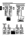
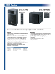
ESPAÑOL
DEUTSCH
Owner’s Manual
Mode d’emploi
Bedienungsanleitung
Manual de instrucciones
使用手卌
ENGLISH
MSR100
FRANÇAIS
POWERED SPEAKER
Contents
Precautions ........................................................... 3
Rear Panel ............................................................. 5
Connection Examples............................................ 6
Specifications ........................................................ 7
General specifications...................................... 7
Amp. Unit ........................................................ 7
Dimensions ........................................................... 7
Performance graph ................................................ 7
Block Diagram ...................................................... 7
漢語
Thank you for choosing the YAMAHA MSR100 powered speaker system. The MSR100 delivers exceptionally high sound quality with smooth, extended
bass response from a compact cabinet. The high-performance internal power amplifier delivers 100
watts, and a mixing function is provided for compatibility with the widest possible range of applications.
In order to take maximum advantage of the
MSR100’s features and ensure maximum performance and longevity, please read this manual carefully before using the MSR100. Keep the manual in a
safe place for future reference.
• Explanation of Graphical Symbols
CAUTION
ENGLISH
RISK OF ELECTRIC SHOCK
DO NOT OPEN
CAUTION: TO REDUCE THE RISK OF
ELECTRIC SHOCK, DO NOT REMOVE
COVER (OR BACK). NO USER-SERVICEABLE
PARTS INSIDE. REFER SERVICING TO
QUALIFIED SERVICE PERSONNEL.
The above warning is located on the
rear of the unit.
The lightning flash with arrowhead symbol
within an equilateral triangle is intended to
alert the user to the presence of uninsulated
“dangerous voltage” within the product’s
enclosure that may be of sufficient magnitude to constitute a risk of electric shock to
persons.
The exclamation point within an equilateral triangle is intended to alert the user to
the presence of important operating and
maintenance (servicing) instructions in the
literature accompanying the product.
IMPORTANT SAFETY INSTRUCTIONS
1
2
3
4
5
6
7
8
9
Read these instructions.
Keep these instructions.
Heed all warnings.
Follow all instructions.
Do not use this apparatus near water.
Clean only with dry cloth.
Do not block any ventilation openings.
Install in accordance with the manufacture’s
instructions.
Do not install near any heat sources such as
radiators, heat registers, stoves or other
apparatus (including amplifiers) that produce
heat.
Do not defeat the safety purpose of the polarized
or grounding-type plug. A polarized plug has two
blades with one wider than the other.
A grounding type plug has two blades and a third
grounding prong. The wide blade or the third
prong are provided for your safety. If the provided
plug does not fit into your outlet, consult an
electrician for replacement of the obsolete outlet.
WARNING
TO REDUCE THE RISK OF FIRE OR ELECTRIC SHOCK,
DO NOT EXPOSE THIS APPARATUS TO RAIN OR MOISTURE.
2
10 Protect the power cord from being walked on or
pinched particularly at plugs, convenience
receptacles, and the point where they exit from
the apparatus.
11 Only use attachments/accessories specified by
the manufacturer.
12 Use only with the cart, stand,
tripod, bracket, or table
specified by the manufacturer,
or sold with the apparatus.
When a cart is used, use
caution when moving the cart/
apparatus combination to
avoid injury from tip-over.
13 Unplug this apparatus during lightning storms or
when unused for long periods of time.
14 Refer all servicing to qualified service personnel.
Servicing is required when the apparatus has
been damaged in any way, such as power-supply
cord or plug is damaged, liquid has been spilled
or objects have fallen into the apparatus, the
apparatus has been exposed to rain or moisture,
does not operate normally, or has been dropped.
WARNING: THIS APPARATUS MUST BE EARTHED
IMPORTANT
GREEN-AND-YELLOW :
EARTH
BLUE :
NEUTRAL
BROWN :
LIVE
ENGLISH
THE WIRES IN THIS MAINS LEAD ARE COLOURED IN
ACCORDANCE WITH THE FOLLOWING CODE:
As the colours of the wires in the mains lead of this apparatus may
not correspond with the coloured markings identifying the terminals in
your plug, proceed as follows:
The wire which is coloured GREEN and YELLOW must be
connected to the terminal in the plug which is marked by the letter E
or by the safety earth symbol
or coloured GREEN and YELLOW.
The wire which is coloured BLUE must be connected to the terminal
which is marked with the letter N or coloured BLACK.
The wire which is coloured BROWN must be connected to the
terminal which is marked with the letter L or coloured RED.
* This applies only to products distributed by YAMAHA KEMBLE
MUSIC (U.K.) LTD.
Precautions
WARNING
Installation
• Connect this unit’s power cord only to an AC outlet of the
type stated in this Owner’s Manual or as marked on the unit.
Failure to do so is a fire and electrical shock hazard.
• Do not allow water to enter this unit or allow the unit to become wet. Fire or electrical shock may result.
• Do not place heavy objects, including this unit, on top of the
power cord. A damaged power cord is a fire and electrical
shock hazard. In particular, be careful not to place heavy objects on a power cord covered by a carpet.
• Do not place a container with liquid or small metal objects on
top of this unit. Liquid or metal objects inside this unit are a
fire and electrical shock hazard.
Operation
• Do not scratch, bend, twist, pull, or heat the power cord. A
damaged power cord is a fire and electrical shock hazard.
• Do not insert or drop metal or flammable objects into the port
of this unit. Fire or electrical shock may result.
• If lightning begins to occur, turn off the power switch of the
unit as soon as possible, and unplug the power cable plug
from the electrical outlet.
• If there is a possibility of lightning, do not touch the power
cable plug if it is still connected. Doing so may be an electrical shock hazard.
• Do not modify the unit. Doing so is a fire and electrical shock
hazard.
• Do not remove the unit’s cover. You could receive an electrical shock. If you think internal inspection, maintenance, or
repair is necessary, contact your dealer.
• Use only the included power cord for this unit. Using other
types may be a fire and electrical shock hazard.
In case an abnormality occurs during operation
• If the power cord is damaged (i.e., cut or a bare wire is exposed), ask your dealer for a replacement. Using the unit with
a damaged power cord is a fire and electrical shock hazard.
• If you notice any abnormality, such as smoke, odor, or noise,
or if a foreign object or liquid gets inside the unit, turn it off
immediately. Remove the power cord from the AC outlet.
Consult your dealer for repair. Using the unit in this condition
is a fire and electrical shock hazard.
• Should this unit be dropped or the cabinet be damaged, turn the
power switch off, remove the power plug from the AC outlet,
and contact your dealer. If you continue using the unit without
heeding this instruction, fire or electrical shock may result.
3
CAUTION
ENGLISH
Installation
• Keep this unit away from the following locations:
- Locations exposed to oil splashes or steam, such as near
cooking stoves, humidifiers, etc.
- Unstable surfaces, such as a wobbly table or slope.
- Locations exposed to excessive heat, such as inside a car
with all the windows closed, or places that receive direct
sunlight.
- Locations subject to excessive humidity or dust accumulation.
• Do not place the power cord close to a heater. It may melt,
causing fire or electrical shock.
• Hold the power cord plug when disconnecting it from an AC
outlet. Never pull the cord. A damaged power cord is a potential fire and electrical shock hazard.
• Do not touch the power plug with wet hands. Doing so is a potential electrical shock hazard.
• This unit has ventilation holes at the rear to prevent the internal temperature rising too high. Do not block them. Blocked
ventilation holes are a fire hazard.
In particular, do not
- place the unit on its side or upside down,
- place the unit in any poorly-ventilated location such as a
bookcase or closet (other than on the dedicated rack),
- cover the unit with a table cloth or place it on a carpet or
bed.
• To relocate the unit, turn the power switch off, remove the
power plug from the AC outlet, and remove all connecting cables. Damaged cables may cause fire or electrical shock.
• Allow enough free space around the unit for normal ventilation. This should be: 30 cm at the sides, 30 cm behind, and 30
cm above. Open a ventilation hole. If the airflow is not adequate, the unit will heat up inside and may cause a fire.
Operation
• Turn off all musical instruments, audio equipment, and
speakers when connecting to this unit. Use the correct connecting cables and connect as specified.
• Always lower the volume control to minimum before turning
on the power to this unit. A sudden blast of sound may damage your hearing.
• Do not output distorted sounds for long periods of time, as
this will cause the speaker to heat up, leading to a fire hazard.
• Do not raise the volume of speakers to a level that makes you
feel uncomfortable. Listening to loud music for long periods
can damage your hearing.
• If you know you will not use this unit for a long period of time,
such as when going on vacation, remove the power plug from
the AC outlet. Leaving it connected is a potential fire hazard.
Maintenance
• To prevent electrical shock when cleaning the unit, remove
the power plug from the AC outlet.
PRECAUTIONS – FOR CORRECT OPERATION –
Connector pin assignments
• XLR-type connectors are wired as follows: pin 1: ground, pin
2: hot (+), and pin 3: cold (–).
Installation
• This speaker system is not magnetically shielded. If a nearby
monitor exhibits any distortion or unnatural color shift, move
the speaker further away from the monitor.
4
Influence on cell phone usage
• Using a cell phone (mobile telephone) near this unit may induce
noise. If noise occurs, use the telephone away from the unit.
Rear Panel
1 POWER Switch
②
③
⑤
④
⑦
⑥
⑧
2 INPUT1 Connector
This dual-mode input connector is a balanced
XLR-3-31 type.
The INPUT1 connector can be set for two types of
input: when the sensitivity switch (C) is set to
MIC microphone-level signals can be connected
directly to the input; when the sensitivity switch
(C) is set to LINE the input accepts line-level signals such as those from a preamplifier or mixer.
3 Sensitivity Switch
Use this switch to set the sensitivity of the
INPUT1 connector to match MIC (microphonelevel) or LINE (line-level) input signals.
⑨
⑩
4 INPUT2 and INPUT3 Connectors
The INPUT2 and INPUT3 connectors are unbalanced phone jacks for direct connection of linelevel audio signals and musical instruments.
5 LEVEL Controls
①
⑪
Adjust the level of the signals received at the
INPUT1, INPUT2, and INPUT3 connectors (2,
4).
6 EQ Controls
HIGH: The HIGH control adjusts the output level at
10 kHz over a ±6 dB range. Rotate clockwise to
boost or counterclockwise to cut.
LOW: The LOW control adjusts the output level at
60 Hz over a ±3 dB range. Rotate clockwise to
boost or counterclockwise to cut.
7 LINK OUT Connector
This is a “direct output“ connector that outputs a
mix of the signals received at the INPUT1,
INPUT2 and INPUT3 connectors (2, 4).
8 MASTER LEVEL Control
Adjusts the overall output level.
9 CLIP Indicator
The CLIP indicator will light red if excessively
high signal levels cause amplifier clipping. If this
occurs, reduce the level of LEVEL controls (5) or
MASTER LEVEL controls (8).
J POWER Indicator
Light green when the POWER switch (A) is
turned on.
K AC IN Connector
Connect the supplied power cord here.
5
ENGLISH
Turns power to the MSR100 on and off. When the
power is turned on the POWER indicator (J)
will light green.
Connection Examples
Connecting a microphone
and other sources directly
ENGLISH
Connecting to a mixer
LINE OUT L
R
Microphone
CD player or Tape deck
Mixer
Keyboad
Daisy chain
LINE OUT L
Mixer
6
R
Specifications
Type
2way Bass Reflex Powered Speaker
Speaker Unit
LF: 200 mm Cone
HF: 25.4 mm Compression Driver
Frequency Range ..................55 Hz—20 kHz (–10 dB)
Cross Over Frequency...........4 kHz
Maximum Output Level ........112 dB (1 m)
Dimension (W×H×D)............275 × 455.5 × 255 mm
Weight..................................11 kg
Color ....................................Black (Approximate Munsell
Value 5 PB2/1)
Accessories...........................Power supply cord 2.5 m (AC
Inlet type)
Option..................................BWS50-190/260/320,
BCS251, BBS251
Amp. Unit
Max Power ...........................100W at 1 kHz, THD=1%,
RL=6Ω
Input Sensitivity ....................INPUT 1: –50 dB* (MIC),
+4 dB* (LINE)
INPUT 2, 3: –10 dB*
Intput Impedance..................INPUT 1, 2, 3: 10 kΩ
Output Sensitivity .................LINK OUT: –10 dB*
Output Impedance................LINK OUT: 10 kΩ
Controls
LEVEL Control .................INPUT 1, 2, 3, MASTER
EQ Control......................LOW: ±3 dB at 60 Hz
HIGH: ±6 dB at 10 kHz
POWER Switch ...............ON/OFF
Connectors
INPUT 1..........................XLR-3-31 (balanced)
INPUT 2, 3......................Phone (unbalanced)
LINK OUT.......................Phone (unbalanced)
Indicator
POWER Indicator............Green LED
CLIP Indicator .................Red LED
Power Requirement
USA and Canada.............AC 120 V, 60 Hz
Europe ............................AC 230 V, 50 Hz
Australia..........................AC 240 V, 50 Hz
Korea..................................AC 220 V, 60 Hz
Power Consumption .............70 W
* 0 dB=0.775 V
Specifications and descriptions in this owner’s manual are
for information purposes only. Yamaha Corp. reserves the
right to change or modify products or specifications at any
time without prior notice. Since specifications, equipment
or options may not be the same in every locale, please
check with your Yamaha dealer.
For European Model
Purchaser/User Information specified in EN55103-1 and
EN55103-2.
Inrush Current: 10 A
Conformed Environment: E1, E2, E3 and E4
Dimensions
Performance Graph
+10
455.5
RESPONSE (dB)
0
-20
-30
-40
255
275
-10
20
100
1k
10k
137
FREQUENCY (Hz)
120
2-M8x25
Block Diagram
INPUT1
(ー50/+4dB)
+4 dB
-50dB
INPUT2
(ー10dB)
LOW
BOOST
LOW
CUT
EQ
LOW
HIGH
MASTER
LEVEL
P.AMP
NW
HF
SUM
INPUT3
(ー10dB)
LINK OUT
(ー10dB)
LF
7
ENGLISH
General specifications
ENGLISH
MEMO
8
Yamaha Manual Library
http://www2.yamaha.co.jp/manual/english/
M.D.G., Pro Audio & Digital Musical Instrument Division, Yamaha Corporation
© 2002 Yamaha Corporation
209AP-01A0
Printed in China