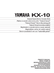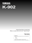
1
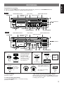
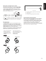
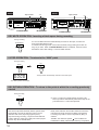
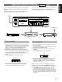
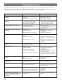
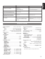
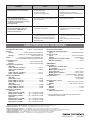
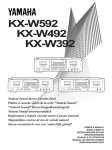
UCA
KX-493/KX-393
Natural Sound Stereo Cassette Deck
Platine à cassette stéréo de la série “Natural Sound”
NATURAL SOUND STEREO CASSETTE DECK KX-493
STANDBY/ON
INTRO SCAN
COUNTER
TIMER
REC
OFF
EJECT
PLAY
YAMAHA GF Head
Cassette Stabilizer
REPEAT AUTO TAPE
RESET
MEMORY
OFF/0-M/FULL
TUNING
PHONES
LEVEL
BIAS ADJUST
PLAY TRIM
0
0
DOLBY NR
OFF/
BALANCE
0
REC
B/
C/MPX
LEVEL
REC/PAUSE MUTE/SEARCH
MIN
MAX
+
+
L
R
MIN
MAX
NATURAL SOUND STEREO CASSETTE DECK KX-393
STANDBY/ON
INTRO SCAN
COUNTER
EJECT
RESET
MEMORY
PHONES
LEVEL
TUNING
0
0
BALANCE
0
DOLBY NR
OFF/ B/ C/MPX
REC
LEVEL
REC/PAUSE MUTE/SEARCH
YAMAHA GF Head
Cassette Stabilizer
MIN
OWNER’S MANUAL
MODE D’EMPLOI
AUTO TAPE
BIAS ADJUST PLAY TRIM
MAX
+
+
L
R
MIN
MAX
Thank you for purchasing this YAMAHA stereo cassette deck.
SAFETY INSTRUCTIONS
CAUTION
RISK OF ELECTRIC SHOCK
DO NOT OPEN
CAUTION: TO REDUCE THE RISK OF ELECTRIC
SHOCK, DO NOT REMOVE COVER (OR BACK).
NO USER-SERVICEABLE PARTS INSIDE. REFER
SERVICING TO QUALIFIED SERVICE PERSONNEL.
÷ Explanation of Graphical Symbols
The lightning flash with arrowhead symbol,
within an equilateral triangle, is intended to
alert you to the presence of uninsulated
“dangerous voltage” within the product's
enclosure that may be of sufficient magnitude
to constitute a risk of electric shock to persons.
The exclamation point within an equilateral
triangle is intended to alert you to the presence
of important operating and maintenance
(servicing) instructions in the literature
accompanying the appliance.
WARNING
TO REDUCE THE RISK OF FIRE OR ELECTRIC
SHOCK, DO NOT EXPOSE THIS APPLIANCE TO RAIN
OR MOISTURE.
1 Read Instructions — All the safety and operating
instructions should be read before the unit is operated.
2 Retain Instructions — The safety and operating
instructions should be retained for future reference.
3 Heed Warnings — All warnings on the unit and in the
operating instructions should be adhered to.
4 Follow Instructions — All operating and other instructions
should be followed.
5 Water and Moisture — The unit should not be used near
water — for example, near a bathtub, washbowl, kitchen
sink, laundry tub, in a wet basement, or near swimming
pool, etc.
6 Carts and Stands — The unit should be used only with a
7 Wall or Ceiling Mounting — The unit should be mounted
to a wall or ceiling only as recommended by the
manufacturer.
8 Ventilation — The unit should be situated so that its
location or position does not interfere with its proper
ventilation. For example, the unit should not be situated on a
bed, sofa, rug or similar surfaces that may block the
ventilation openings: or placed in a built-in installation, such
as a bookcase or cabinet that may impede the flow of air
through the ventilation openings.
9 Heat — The unit should be situated away from heat
sources such as radiators, stoves, or other units that
produce heat.
10 Power Sources — The unit should be connected to a
power supply only of the type described in the operating
instructions or as marked on the unit.
11 Power-Cord Protection — Power-supply cords should
be routed so that they are not likely to be walked on or
pinched by items placed upon or against them, paying
attention to receptacles, and the point where they exit from
the unit.
12 Cleaning — The unit should be cleaned only as
recommended by the manufacturer.
13 No Use Periods — The power cord of the unit should be
unplugged from the outlet when left unused for a long
period of time.
14 Object and Liquid Entry — Care should be taken so
that objects do not fall into and liquids not spilled into the
inside of the unit.
15 Damage Requiring Service — The unit should be
serviced by qualified service personnel when:
A. The power-supply cord or the plug has been damaged;
or
B. Objects have fallen, or liquid has been spilled into the
unit; or
C. The unit has been exposed to rain; or
D. The unit does not appear to operate normally or exhibits
a marked change in performance; or
E. The unit has been dropped, or the cabinet damaged.
16 Servicing — The user should not attempt to service the
unit beyond those means described in the operating
instructions. All other servicing should be referred to
qualified service personnel.
cart or stand that is recommended by the manufacturer.
17 Grounding or Polarization — The precautions should be
6A An applicance and cart
taken so that the grounding or polarization of an unit is not
defeated.
combination should be moved with
care. Quick stops, excessive force,
and uneven surfaces may cause the
unit and cart combination to overturn.
2
This unit is not disconnected from the AC power source
as long as it is connected to the wall outlet, even if the
unit itself is turned off. This state is called the standby
mode. In this state, the unit is designed to consume a
very small quantity of power.
FCC INFORMATION (U.S.A.)
1. IMPORTANT NOTICE: DO NOT MODIFY THIS UNIT!
This product, when installed as indicated in the
instructions contained in this manual, meets FCC
requirements. Modifications not expressly approved by
Yamaha may void your authority, granted by the FCC, to
use the product.
2. IMPORTANT: When connecting this product to
accessories and/or another product use only high quality
shielded cables. Cables supplied with this product
MUST be used. Follow all installation instructions.
Failure to follow instructions could void your FCC
authorization to use this product in the USA.
3. NOTE: This product has been tested and found to
comply with the requirements listed in FCC Regulations,
Part 15 for Class "B" digital devices. Compliance with
these requirements provides a reasonable level of
assurance that your use of this product in a residential
environment will not result in harmful interference with
other electronic devices. This equipment generates/uses
radio frequencies and, if not installed and used
according to the instructions found in the users manual,
may cause interference harmful to the operation of other
electronic devices. Compliance with FCC regulations
does not guarantee that interference will not occur in all
installations. If this product is found to be the source of
interference, which can be determined by turning the
product "OFF" and "ON", please try to eliminate the
problem using one of the following measures:
Relocate this product or the device that is being affected
by the interference.
Utilize power outlets that are on different branch (circuit
breaker or fuse) circuits or install AC line filter/s.
In the case of radio or TV interference, relocate/reorient
the antenna. If the antenna lead-in is 300 ohm ribbon
lead, change the lead-in to coaxial type cable.
If these corrective measures do not produce satisfactory
results, please contact your local retailer that is
authorized to distribute this type of product. If you
cannot locate the appropriate retailer, please contact
Yamaha Electronics Corp., U.S.A.
6660 Orangethorpe Ave, Buena Park, CA 90620
The above statements apply ONLY to those products
distributed by Yamaha Corporation of America or its
subsidiaries.
ENGLISH
CAUTION: READ THIS BEFORE OPERATING
YOUR UNIT.
1. This unit is a sophisticated stereo cassette deck. To ensure
proper operation for the best possible performance, please
read this manual carefully.
2. Choose the installation location of your unit carefully. Avoid
placing it in direct sunlight or close to source of heat. Also
avoid locations subject to vibration and excessive dust, heat,
cold or moisture. Keep it away from sources of hum such as
transformers or motors.
3. Do not open the cabinet as this may result in damage to the
deck or electrical shock. If a foreign object should get into
the deck, contact your local dealer.
4. When removing the power plug from the wall outlet, always
pull directly on the plug; never pull the cord itself.
5. Do not apply excessive force when operating switches and
knobs.
6. When moving the deck, be sure to first pull out the power
plug and remove all cords connecting the deck to other
equipment.
7. Do not attempt to clean this unit with chemical solvents as
this may damage the finish. Use a clean, dry cloth.
8. Never allow metallic items (e.g. screwdrivers, tools, etc.) to
come near the record/playback head assembly. Doing so
may not only scratch or damage the head’s mirror-smooth
finish, it may also change the magnetic characteristics of the
heads, causing a deterioration in reproduction quality.
9. Although the record/playback head used in this unit is a high
quality head with outstanding reproduction characteristics, it
can become dirty through the use of old tapes or from dust
accumulation over time. This can have a serious effect on
reproduction quality. Clean the heads regularly with one of
the commonly available head cleaners or with cleaning
solutions as explained later in this manual.
10. Be sure to read the “TROUBLESHOOTING” section of this
manual for advice on common operating errors before
concluding that your unit is faulty.
11. Keep this manual in a safe place for future reference.
12. Voltage Selector (General model only)
The voltage selector on the rear panel of this unit must
be set for your local mains voltage BEFORE plugging in
the AC mains supply. (Voltage selector adjustable
between 110/120/220/240 V AC.)
Note
Please check the copyright laws in your country to record from
records, compact discs, radio, etc. Recording of copyright
material may infringe copyright laws.
We Want You Listening For A Lifetime
YAMAHA and the Electronic Industries Association's
Consumer Electronics Group want you to get the most out of
your equipment by playing it at a safe level. One that lets the
sound come through loud and clear without annoying blaring
or distortion – and, most importantly, without affecting your
sensitive hearing.
Since hearing damage from loud sounds
is often undetectable until it is too late,
YAMAHA and the Electronic Industries
Association's Consumer Electronics
We
Want You
Group recommend you avoid prolonged
LISTENING
For A Lifetime
exposure to excessive volume levels.
FOR CANADIAN CUSTOMERS
TO PREVENT ELECTRIC SHOCK, MATCH WIDE
BLADE OF PLUG TO WIDE SLOT AND FULLY
INSERT.
THIS CLASS B DIGITAL APPARATUS MEETS ALL
REQUIREMENTS OF THE CANADIAN
INTERFERENCE-CAUSING EQUIPMENT
REGULATIONS.
3
This owner’s manual covers YAMAHA cassette deck models KX-493 and KX-393. Please check which model
you have purchased and read the sections that apply to your particular model. There may be some
unnecessary items, so please skip them accordingly.
TABLE OF CONTENTS
FEATURES .......................................................................... 4
CONNECTIONS .................................................................. 4
PLAYBACK ......................................................................... 5
SELECTION SEARCH ..................................................... 7
INTRO SCAN ................................................................... 7
MEMORY STOP OPERATION ......................................... 8
REPEAT PLAYBACK (KX-493 only) ................................ 8
RECORDING ...................................................................... 9
REC MUTE OPERATION .............................................. 12
0-STOP OPERATION .................................................... 12
REC RETURN OPERATION .......................................... 12
TIMER RECORDING/PLAYBACK (KX-493 only) .............
Timer recording ............................................................
Timer playback .............................................................
CASSETTE TAPES ............................................................
OPENING AND CLOSING THE SUB PANEL
(KX-493 only) ....................................................................
OPTIONAL REMOTE CONTROL TRANSMITTER ............
MAINTENANCE ................................................................
TROUBLESHOOTING ......................................................
SPECIFICATIONS .............................................................
13
13
13
14
15
15
15
16
17
FEATURES
÷ Dolby HX Pro Dynamic Bias Servo
÷ Dolby B/C Noise Reduction
÷ Secure Holding Damper Cassette Stabilizer allows you
to reduce unwanted vibration and modulation noise
÷ Fine Adjustment of Recording Characteristics with Auto
Tape Tuning and Bias Adjust Control
÷ 160 kHz High Recording Bias prevents cross
modulation beat distortion that can occur between the
recording bias and the recording signal’s high
frequency content (KX-493 only)
÷ Play Trim Control for improved playback compatibility
with other decks
÷ 0-M/FULL Repeat Playback (KX-493 only), Selection
Search and Bi-Directional Intro Scan
÷ Recording Mute function
CONNECTIONS
L
R
LINE IN
REC
LINE OUT
PLAY
(U.S.A. model)
To an AC outlet
REAR PANEL CONNECTIONS
Make sure that power to both the deck and your amplifier/receiver are turned off
before making any connections.
REC OUT TAPE PB
L
R
Amplifier or receiver
4
÷ The White plug on the paired connecting cables corresponds to the Left channel and
the Red plug corresponds to the Right channel. Make sure that the left and right channel
connections are properly made, and that the plugs are inserted firmly.
÷ The LINE OUT/PLAY jacks on the deck should be connected to the TAPE PB (Playback/
Input) jacks on your amplifier/receiver, and the LINE IN/REC jacks on the deck should
be connected to the REC OUT (Rec/Output) jacks on your amplifier/receiver.
÷ Connect the power cord to an AC wall outlet or to an AC outlet on the rear panel of your
amplifier/receiver (if provided).
ENGLISH
PLAYBACK
Preparation for playback
÷ Be sure to set the TIMER switch to the OFF position (KX-493 only), then turn on the STANDBY/ON switch.
÷ Set your amplifier or receiver to cassette deck function mode.
MPX FILTER indicator
KX-493
B/
When a tape is loaded, the corresponding
tape type indicator lights.
C indicators
STANDBY/ON
&
NATURAL SOUND STEREO CASSETTE DECK KX-493
3
STANDBY/ON
INTRO SCAN
COUNTER
TIMER
REC
OFF
PLAY
EJECT
MEMORY
OFF/0-M/FULL
TUNING
LEVEL
BIAS ADJUST
PLAY TRIM
0
0
MIN
–
MAX
PHONES
+
–
+
L
B/
REC
C/MPX
!
LEVEL
R
MIN
MAX
PLAY TRIM
REC/PAUSE
PHONES LEVEL
1
⁄
DOLBY NR
OFF/
BALANCE
0
REC/PAUSE MUTE/SEARCH
YAMAHA GF Head
Cassette Stabilizer
TIMER
REPEAT AUTO TAPE
RESET
PHONES
2
MPX FILTER indicator
KX-393
B/
When a tape is loaded, the corresponding
tape type indicator lights.
C indicators
STANDBY/ON
&
NATURAL SOUND STEREO CASSETTE DECK KX-393
3
STANDBY/ON
INTRO SCAN
COUNTER
AUTO TAPE
RESET
MEMORY
PHONES
LEVEL
TUNING
BIAS ADJUST PLAY TRIM
0
EJECT
0
BALANCE
0
B/
C/MPX
PHONES
1
MAX
–
+
–
+
L
REC/PAUSE MUTE/SEARCH
R
MIN
PLAY TRIM
PHONES LEVEL
!
LEVEL
YAMAHA GF Head
Cassette Stabilizer
MIN
⁄
DOLBY NR
OFF/
REC
MAX
REC/PAUSE
2
Press STANDBY/ON to turn this unit on. Press again to set it to the standby mode.
Please note that this unit is designed to consume a very small quantity of power when set to the standby mode.
3
2
1
EJECT
Insert the cassette with the
exposed tape side facing down and
the side to be played facing you.
To close the compartment, push in
the compartment door until it locks
shut.
DOLBY NR
OFF/
B/
C/MPX
‹
See next page.
5
To stop playback:
PLAY TRIM control adjustment
Press the & button.
When the level of high frequencies is too boosted or
absent while playing a tape recorded on another cassette
deck, adjust the high frequency response with the PLAY
TRIM control.
To fast forward the tape:
Press the ⁄ button.
When high frequencies are
absent, boost the high
frequencies.
When high frequencies are
too boosted, attenuate the
high frequencies.
To fast rewind the tape:
Press the ! button.
To adjust the volume level:
KX-493
Use the volume control of the amplifier or receiver.
PLAY TRIM
PLAY TRIM
0
0
PLAY TRIM
PLAY TRIM
0
0
To use headphones for private listening:
Insert the headphones plug into the PHONES jack.
To adjust the headphones level:
Use the PHONES LEVEL control.
DOLBY NR button setting (in step 2)
DOLBY NR (OFF/
B/
C/MPX) button
Be sure to set the DOLBY NR (OFF/
B/
C/MPX)
button according to the system used for recording. Each
time this button is pressed, Dolby NR switches as follows:
KX-393
B(MPX OFF) For a tape recorded with DOLBY B NR
Only the
B indicator lights.
3
∞
C(MPX OFF) For a tape recorded with DOLBY C NR
Only the
C indicator lights.
∞
B MPX ON
∞
C MPX ON
∞
OFF
(available only for recording)
(available only for recording)
1
For a tape recorded with DOLBY NR
OFF
No indicator lights.
1
2
3
10 dB
Note: The MPX filter settings are explained on page 9.
Noise Reduction Responce
NR-OFF
B-NR
10 dB
10 dB
20
6
C-NR
100
1k
10k 20k
Hz
100
1k
10kHz
2
3
High frequency sound is
too boosted.
Flat.
High frequency sound is
absent.
ENGLISH
INTRO indicator
NATURAL SOUND STEREO CASSETTE DECK
‹
STANDBY/ON
INTRO SCAN
⁄
EJECT
!
REC/PAUSE MUTE/SEARCH
YAMAHA GF Head
Cassette Stabilizer
@ INTRO SCAN #
MUTE/SEARCH
SELECTION SEARCH - To play back a desired selection by searching for the
beginning of the selection
To search for the next selection
To search for the beginning of the current
selection
To search for the selection located
before the current selection
When the beginning of the current
selection is played:
⁄
MUTE/SEARCH
!
MUTE/SEARCH
!
+
+
MUTE/SEARCH
+
The ! or ⁄ button and the MUTE/SEARCH button should be pressed simultaneously.
INTRO SCAN - To play back the beginning of each selection automatically
To play back each selection in the reverse
direction:
@ INTRO SCAN
The INTRO @
indicator lights
during reverse
intro scan.
To play back each selection in the forward
direction:
To resume normal playback when the
desired selection is found:
‹
INTRO SCAN #
The INTRO #
indicator lights
during forward
intro scan.
3
5
Notes on Selection search and Intro scan
÷ The blank interval between selections must be at least 4 seconds.
÷ Selection search and Intro scan may not operate properly with tapes recorded with a low record level or with
excessive noise.
7
REPEAT OFF/0-M/FULL indicator
KX-493
KX-393
MEMORY indicator
MEMORY indicator
‹
‹
NATURAL SOUND STEREO CASSETTE DECK KX-493
NATURAL SOUND STEREO CASSETTE DECK KX-393
STANDBY/ON
STANDBY/ON
INTRO SCAN
COUNTER
TIMER
REC
OFF
RESET
PLAY
PHONES
REPEAT AUTO TAPE
MEMORY
OFF/0-M/FULL
TUNING
LEVEL
BIAS ADJUST
PLAY TRIM
0
EJECT
0
INTRO SCAN
DOLBY NR
OFF/
BALANCE
0
REC
B/
COUNTER
C/MPX
RESET
PHONES
MAX
–
+
–
+
L
R
MIN
LEVEL
BIAS ADJUST PLAY TRIM
0
EJECT
MIN
TUNING
DOLBY NR
OFF/
B/
C/MPX
LEVEL
REC/PAUSE MUTE/SEARCH
YAMAHA GF Head
Cassette Stabilizer
AUTO TAPE
MEMORY
0
BALANCE
0
REC
LEVEL
REC/PAUSE MUTE/SEARCH
YAMAHA GF Head
Cassette Stabilizer
MAX
MIN
REPEAT
OFF/0-M/FULL
COUNTER MEMORY
! ⁄
COUNTER RESET
MAX
–
+
–
+
L
R
MIN
MAX
COUNTER RESET
COUNTER MEMORY
! ⁄
MEMORY STOP OPERATION - To return to the desired position
Pressing the MEMORY button
memorizes the desired counter
reading. The MEMORY indicator
lights.
MEMORY
3
During fast forwarding or
rewinding, the tape will stop at the
counter reading point where the
MEMORY button was pressed.
To cancel the memorized
counter reading, press the
MEMORY button again. The
MEMORY indicator goes out.
⁄
!
MEMORY
or
REPEAT PLAYBACK ( KX-493 only)
0-M (a section) repeat
With this function, a desired section can be played
repeatedly up to 8 times.
1 Press the REPEAT OFF/0-M/FULL button so that the
REPEAT 0-M indicator lights.
REPEAT
OFF/0-M/FULL
The tape is rewound until the counter has returned to
the beginning of the section. The deck then enters the
playback mode and the specified section is played
repeatedly.
Note:
The length between the start and end points of the 0-M
repeat section should be more than 4 counts.
Full repeat
2 Press the RESET button at the beginning of the section
you want to play repeatedly. The counter on the
display is reset to "0000".
RESET
3 Press the MEMORY button at the end of the section
during playback. The MEMORY indicator on the
display lights up, and the tape immediately begins
rewinding.
MEMORY
With this function, the cassette side being played can be
repeated up to 8 times.
Press the REPEAT OFF/0-M/FULL button so that the
REPEAT FULL indicator lights.
REPEAT
OFF/0-M/FULL
3
To cancel repeat playback
To cancel the 0-M repeat or Full repeat, press the
REPEAT OFF/0-M/FULL button so that both REPEAT 0-M
and REPEAT FULL indicators go off. Each time this button
is pressed, Repeat mode switches as follows:
3 0-M
8
‹
repeat
3
Full repeat
3 OFF
ENGLISH
RECORDING
Preparation for recording
÷ Be sure to set the TIMER switch to the OFF position (KX-493 only), then turn on the STANDBY/ON switch.
÷ Set your amplifier or receiver to cassette deck function mode.
KX-493
TAPE TUNNG indicator
Tape counter
SYNCHRO and REC
indicators
STANDBY/ON
MPX FILTER indicator
PEAK level meters
6
NATURAL SOUND STEREO CASSETTE DECK KX-493
STANDBY/ON
INTRO SCAN
COUNTER
TIMER
REC
OFF
PLAY
EJECT
MEMORY
OFF/0-M/FULL
TUNING
PHONES
LEVEL
BIAS ADJUST
PLAY TRIM
0
0
MIN
COUNTER RESET
–
MAX
+
–
BALANCE
0
+
L
REC
B/
C indicators
B/
C indicators
C/MPX
LEVEL
R
MIN
2
MAX
BIAS ADJUST
4 5
COUNTER MEMORY
B/
DOLBY NR
OFF/
REC/PAUSE MUTE/SEARCH
YAMAHA GF Head
Cassette Stabilizer
1
REPEAT AUTO TAPE
RESET
3
MUTE/SEARCH
KX-393
TAPE TUNNG indicator
Tape counter
STANDBY/ON
MPX FILTER indicator
PEAK level meters
SYNCHRO and REC
indicators
6
NATURAL SOUND STEREO CASSETTE DECK KX-393
STANDBY/ON
INTRO SCAN
COUNTER
AUTO TAPE
RESET
MEMORY
PHONES
LEVEL
TUNING
BIAS ADJUST PLAY TRIM
BALANCE
0
0
0
EJECT
DOLBY NR
OFF/
REC
B/
C/MPX
LEVEL
REC/PAUSE MUTE/SEARCH
YAMAHA GF Head
Cassette Stabilizer
MIN
1
COUNTER RESET
1
MAX
+
–
+
BIAS ADJUST
COUNTER MEMORY
Insert the cassette with
the exposed tape side
facing down and the
side to be recorded
facing you. To close the
compartment, push in
the compartment door
until it locks shut.
EJECT
–
L
R
4
MIN
5
2
2
MAX
3
3
MUTE/SEARCH
REC/PAUSE
DOLBY NR
OFF/
B/
C/MPX
]
Play the
program
source to be
recorded.
REC
See next page.
4
AUTO TAPE
TUNING
5
BALANCE
See “AUTO
TAPE TUNING
button” (page
10).
REC
LEVEL
Shape of REC controls are
slightly different with KX-393.
0
L
R
MIN
MAX
6
‹
See “Setting the recording
level” (page 11).
To stop recording:
Tape counter and COUNTER RESET button
Press the & button.
Before starting recording, press the RESET button to set
the counter reading to “0000”. Use this counter to aid in
locating a point on a tape.
To stop recording temporarily:
Press the REC/PAUSE button. To resume recording,
press the ‹ button.
9
DOLBY NR button setting (in step 2)
DOLBY NR (OFF/ B/ C/MPX) button
Each time this button is pressed, Dolby NR switches as
follows:
3
B(MPX OFF) Recording with DOLBY B NR
Only the
B indicator lights.
∞
C(MPX OFF) Recording with DOLBY C NR
Only the
C indicator lights.
∞
B MPX ON
Recording an FM broadcast with
DOLBY B NR
B and MPX FILTER indicators light.
∞
C MPX ON
Recording an FM broadcast with
DOLBY C NR
C and MPX FILTER indicators light.
∞
OFF
Recording with no noise reduction
No indicator lights.
÷ MPX filter:
FM stations transmit a 19 kHz pilot signal in addition to
the broadcast program. Sometimes this pilot signal
may leak into the audio output depending on the tuner
and broadcast conditions. This signal can cause
improper operation of the Dolby NR systems.
Activating the MPX filter (B TYPE/C TYPE MPX ON
settings) will effectively remove the signal.
To clear Auto Tape Tuning setting, press the AUTO TAPE
TUNING button once again, or load any cassette tape of
different type.
* When recording on the other side of the tape, another
Auto Tape Tuning is unnecessary.
When recording on the same type cassette tape of a
different brand, another Auto Tape Tuning is advisable
for much more accurate setting of the recording
characteristics.
AUTO TAPE TUNING
The Auto Tape Tuning function improves the quality of
your recording, permitting critical adjustment of the
deck’s recording bias and sensitivity for best results
with every tape you use.
With the Auto Tape Tuning function, the recording
characteristics (recording bias and sensitivity) are
automatically adjusted while recording and playback
operations in about 20 seconds, to accurately match
the characteristics of loaded tape.
For example, the recorded (output) level (A in the
figure) may differ from recording (input) level (B in the
figure), due to widely varying characteristics of
cassette tapes between brands.
Using the Auto Tape Tuning function, these differences
are effectively eliminated by adjusting the recording
bias (for high frequencies) and sensitivity (for overall
frequencies) according to the loaded cassette tape,
making a significant contribution to overall recording
quality (C in the figure).
Pressing this button during the REC/PAUSE mode will
activate the Auto Tape Tuning that makes it possible to
internally determine the optimum recording characteristics
(bias and recording sensitivity) according to the loaded
cassette tape in about 20 seconds.
To perform the Auto Tape Tuning, send the tape leader
part forward and set the PLAY/TRIM control and the BIAS
ADJUST control to the center position before pressing the
AUTO TAPE TUNING button. When the Auto Tape Tuning
is completed, the TAPE TUNING indicator lights. After
completion of Auto Tape Tuning, the tape automatically
rewinds to the point where the Auto Tape Tuning began
and the REC/PAUSE mode is engaged. The bias
adjustment with the BIAS ADJUST control is possible
even after this tuning.
10
Output Level (dB)
AUTO TAPE TUNING button (in step 4)
B Input Level
A
Frequency (Hz)
C
1
2
3
Frequency (Hz)
1
2
3
METAL
NORM
HIGH
ENGLISH
Play the loudest passage of the source to be recorded
and watch the meter readings. Adjust the REC LEVEL
control so that the highest peak may not exceed the
optimum levels of each tape type. Normally, it is best to
adjust the BALANCE control such that the LEFT and
RIGHT meter readings are even.
Output Level (dB)
Setting the recording level (in step 5)
Insufficient bias (High frequencies are distorted.)
Optimum bias
Excessive bias (High frequencies are absent.)
L
dB
– 30
20
17
14
12
10
8
6
4
0
2
4
6
8+
R
÷ The
mark indicates the Dolby noise reduction system
standard level and corresponds to the -2 dB segment
on the meter.
Bias adjustment
The BIAS ADJUST control is for fine adjustment of the
recording bias. Normally, it is not necessary to adjust this
control since the recording bias can be automatically
adjusted by the built-in Auto Tape Selector and the AUTO
TAPE TUNING button for different tape types.
However, if you feel that your recording needs further bias
adjustment (to compensate for absent or distorted high
frequencies), adjust this control to your liking.
When high frequencies are
distorted, increase the
recording bias by turning
the BIAS ADJUST control
clockwise.
Synchronized recording function
When operating this unit in combinaton with the YAMAHA
CD Player which has SYNCHRO button on its remote
control transmitter, CD Synchronized recording function
can be utilized. This function is operated with the remote
control transmitter of the CD Player. (Regarding the
operation, refer to the manual of the CD Player.)
SYNCHRO indicator of this unit lights when the SYNCHRO
button of the remote controller is pressed.
When high frequencies are
absent, decrease the recording
bias by turning the BIAS
ADJUST control
counterclockwise.
KX-493
BIAS ADJUST
0
BIAS ADJUST
0
KX-393
BIAS ADJUST
0
BIAS ADJUST
0
11
KX-493
KX-393
Tape counter
!
Tape counter
!
NATURAL SOUND STEREO CASSETTE DECK KX-493
NATURAL SOUND STEREO CASSETTE DECK KX-393
STANDBY/ON
STANDBY/ON
INTRO SCAN
COUNTER
TIMER
REC
OFF
RESET
PLAY
PHONES
REPEAT AUTO TAPE
MEMORY
OFF/0-M/FULL
TUNING
LEVEL
BIAS ADJUST
PLAY TRIM
0
0
EJECT
YAMAHA GF Head
Cassette Stabilizer
INTRO SCAN
DOLBY NR
OFF/
BALANCE
0
REC
B/
COUNTER
C/MPX
RESET
PHONES
+
–
+
L
R
MIN
LEVEL
MAX
DOLBY NR
OFF/
B/
C/MPX
MUTE/SEARCH
0
BALANCE
0
REC
LEVEL
REC/PAUSE MUTE/SEARCH
YAMAHA GF Head
Cassette Stabilizer
MIN
COUNTER RESET
BIAS ADJUST PLAY TRIM
0
EJECT
–
MAX
TUNING
LEVEL
REC/PAUSE MUTE/SEARCH
MIN
AUTO TAPE
MEMORY
MAX
COUNTER RESET
–
+
–
+
L
R
MIN
MAX
MUTE/SEARCH
REC MUTE OPERATION - Inserting a blank space during recording
During recording
A 4-second blank interval is automatically recorded on the tape, and then the
deck enters Rec/Pause mode.
If a blank interval longer than 4 seconds is desired, keep pressing the button as
long as you want. When the MUTE/SEARCH button is released, the deck enters
Rec/Pause mode after making a 4-second blank interval.
MUTE/SEARCH
0-STOP OPERATION - To return to the “0000” point
During recording
RESET
3
!
The tape will be automatically rewound to the “0000” point.
The “0000” point is memorized.
REC RETURN OPERATION - To return to the point at which the recording previously
started
During recording
!
DOLBY HX PRO DYNAMIC BIAS SERVO SYSTEM
This unit incorporates the Dolby HX Pro system which
automatically controls the effective bias to reduce
distortion and noise, improving high frequency
response during recording. Tapes recorded with this
system retain the same high quality even when played
back on any other cassette deck.
12
÷ If the ! button is pressed during recording, Rec
Return operation automatically rewinds the tape to the
point where the ‹ button was pressed.
Dolby noise reduction and HX Pro headroom extension
manufactured under license from Dolby Laboratories
Licensing Corporation. HX Pro originated by Bang &
Olufsen.
"DOLBY", the double-D symbol
and "HX PRO" are
trademarks of Dolby Laboratories Licensing Corporation.
With a commercially available audio timer it is possible to
make recordings and initiate playback automatically at
any time.
Make sure that all power cord connections between the
timer and amplifier/receiver are properly made.
For details, refer to the instructions of your audio timer.
No change in any of the other connections between the
deck and amplifier/receiver, etc., is necessary.
TIMER
NATURAL SOUND STEREO CASSETTE DECK KX-493
STANDBY/ON
INTRO SCAN
COUNTER
TIMER
REC
OFF
PLAY
EJECT
REPEAT AUTO TAPE
RESET
MEMORY
OFF/0-M/FULL
TUNING
PHONES
LEVEL
BIAS ADJUST
PLAY TRIM
0
0
DOLBY NR
OFF/
BALANCE
0
REC
B/
C/MPX
LEVEL
REC/PAUSE MUTE/SEARCH
YAMAHA GF Head
Cassette Stabilizer
MIN
MAX
–
+
–
+
L
R
MIN
MAX
To an AC outlet
Tuner
Amplifier or receiver
Timer recording
Audio timer
Timer playback
1. After turning on the power to each component, select
the station on your tuner which you want to record and
turn down the volume on your amplifier/receiver. This
will have no effect on the recording signal level.
Remember to set the proper recording level.
2. Set the timer to the desired recording start and stop
times. It is advisable to set the timer to begin recording
slightly before and end slightly after the actual
broadcast receiving time to leave some room for later
editing.
3. Set the TIMER switch to the REC position.
1. Turn on the amplifier/receiver and adjust the volume
and tone controls.
2. Set the input mode selector of your amplifier/receiver to
the cassette deck function mode.
3. Set the timer to the time you wish to start and stop
playback.
4. Set the TIMER switch to the PLAY position.
TIMER
REC
OFF
PLAY
TIMER
REC
OFF
PLAY
4. The timer will send power to the amplifier/receiver,
tuner and deck at the preset time, turning all the
components on and initiating the recording.
5. At the preset time, the timer will turn power on to the
amplifier/receiver and cassette deck and begin
playback. It will shut power off at the preset time as
well ending playback.
Note: Whenever the timer recording/playback is not
intended, make sure to set the TIMER switch to OFF
position to prevent the unnecessary recording/playback.
÷ If the TIMER switch is set to REC position and the
power is supplied (plugging in the power cord or
automatically supplying the power after power failure,
etc.), the deck automatically enters Rec mode and the
contents of the cassette tape inserted in the deck will
be erased.
13
ENGLISH
TIMER RECORDING/PLAYBACK ( KX-493 only)
CASSETTE TAPES
CASSETTE TAPES
There are many different types of cassette tapes
available. However, they all conform to standard
specifications so any brand may be used with the deck.
÷ Classification of Cassette Tapes by Formulation
Cassette tapes are available in four basic types
depending on their formulation, or type of magnetic
material and manufacturing process. These four types
are commonly known as Normal (Type I/NORM),
Chrome (Type II/HIGH <CrO2>), Ferrichrome (Type III/
FeCr), and Metal (Type IV/METAL), and they each
require specific tape deck adjustments for optimum
performance.
* YAMAHA does not recommend the use of 120 minute
length cassettes since the extreme thinness of the tape
makes them susceptible to mechanical and recording
problems.
AUTO TAPE SELECTOR DETECTION SLOTS
The deck has a built-in Auto Tape Selector which
automatically adjusts for the proper bias, level and
equalization according to the tape formulation — all you
have to do is load a cassette and the Auto Tape Selector
does the rest.
The Auto Tape Selector determines which type of tape is
loaded by sensing detector slots in the top of the tape
shell. Each tape formulation has its own characteristic
hole markings standardized by the tape industry.
÷ Early model Metal (Type IV/Metal) tape formulation
cassette shells do not have the slots for Auto Tape
Selector operation. As a result, early model Metal type
tapes recorded on another deck will be played back
with the deck at the Chrome (Type II/HIGH <CrO2>)
settings. YAMAHA does not recommend using this kind
of tape.
÷ The deck does not have the required setting for
Ferrichrome (Type III/FeCr) tape, since this tape
formulation is not widely used. Should you use a
Ferrichrome tape, it will be recorded and played back
at the Normal (Type I/NORM) settings, which will result
in an unnatural high frequency emphasis. This effect
may be compensated for somewhat by adjusting the
BIAS ADJUST to the plus (+) direction during
recording, or by using the PLAY TRIM control and/or
the tone controls of your amplifier/receiver during
playback.
TYPE II
Detector slots
14
PROTECTING YOUR RECORDINGS
All cassette tapes are provided with erasure protection
holes to prevent accidental erasure of recorded contents.
There is a small tab covering the hole on each side of the
cassette, and it should be broken off after recording the
tape. Without this tab covering the hole, it is impossible to
record onto that tape. Thus, you can safely protect a
recording for as long as you wish without fear of
accidental erasure. Should you wish to use a cassette
tape protected in this way for recording, simply covering
the hole with adhesive tape will permit erasure and rerecording.
÷ When using Chrome (Type II/HIGH <CrO2>) or Metal
(Type IV/METAL) tapes, make sure you do not cover
the hole intended for the Auto Tape Selector operation.
TAKING UP SLACK IN THE TAPE
As a precaution against tape entanglement and damage,
remove any slack in the tape before inserting cassettes
into the deck. This is accomplished by inserting a pencil,
pen or similar object into one of the spools and gently
winding it until all the slack is removed. You do not have
to wind it too tightly.
Be careful not to touch the tape part itself. It is very
delicate and touching it may damage the tape and its
recorded contents.
TYPE IV
Detector slots
STORING CASSETTES
After putting a cassette tape back into its case, store it in
a location away from exposure to direct sunlight, humidity,
high temperatures, and magnetic fields (away from
television sets, speakers, etc.). High temperatures and
humidity will damage the tape itself, while exposure to
magnetic fields may cause a loss of recorded material.
Avoid touching the tape surface with your fingers, since
dirt or finger oil will contaminate the deck’s heads.
To open the sub panel
ENGLISH
OPENING AND CLOSING THE SUB PANEL
( KX-493 only)
To close the sub panel
OPTIONAL REMOTE CONTROL TRANSMITTER
With the optional remote control transmitter RKX1, you can
operate this unit at your listening position. For details,
refer to the instruction manual supplied with the remote
control transmitter.
¤
SINGLE DECK
REMOTE CONTROL OPERATION RANGE
Remote sensor
‹
INTRO SCAN
DOUBLE DECK
DUBBING
DECK A/B
DIR A
COUNTER
!
DIR B
⁄
7 m (23 feet)
SEARCH
RESET
!
REC/PAUSE REC MUTE
PLAY
⁄
STOP
RKX1
30°
s
30°
MAINTENANCE
CLEANING OF THE TAPE PATH
Continued high quality performance of your deck is
dependent upon periodic cleaning of the heads, capstan,
pinch roller, and all surfaces over which the tape travels.
Normal use will cause an accumulation of dirt and dust on
the heads, capstans, and pinch rollers. This can lead to
poor sound quality, drop outs (intervals with no sound),
unsteady tape speed, loss of high frequency response,
etc.
Thus, clean the heads and all surfaces over which the
tape travels with a commercially available cleaning
cassette and fluid type cleaner.
Inside of the cassette compartment
Heads
Capstan
Pinch roller
DEMAGNETIZATION
After 20-30 hours of use, enough residual magnetism will
build up on the heads to cause poor high frequency
reproduction. At this time you should use a commercially
available head demagnetizer.
÷ When cleaning the tape path or demagnetizing the
heads, be sure to follow carefully the instructions of the
concerning materials such as cleaning fluid or head
demagnetizer.
15
TROUBLESHOOTING
If your cassette deck fails to operate normally, check the following table. It lists common operating errors and simple
measures which you can take to correct the problem. If it cannot be corrected, or the symptom is not listed, disconnect
the deck’s power cord and contact your authorized YAMAHA dealer or service center for help.
Fault
Cause
Cure
Tape doesn’t move in recording or
playback.
÷ Power plug is not properly plugged in.
÷ End of tape.
÷ Cassette shell is warped or damaged.
÷ Reinsert plug properly.
÷ Rewind tape or flip it over.
÷ Do not play damaged tapes.
It happens that this unit does not work
normally.
÷ There is an influence of strong external
noise (lightning, excessive static
electricity, etc.) or a misoperation was
performed while using this unit.
÷ Turn this unit power off and disconnect
the AC power from the AC outlet. After
about 30 seconds have passed,
connect the power and try again.
REC/PAUSE button fails to function.
÷ No cassette tape loaded.
÷ Protective tabs are broken off.
÷ Load a cassette tape.
÷ Change tape or cover protective hole
with adhesive tape.
Sounds become faint and sometimes
inaudible.
÷ Head is dirty.
÷ Head is magnetized.
÷ Clean head.
÷ Demagnetize head using head
demagnetizer.
÷ Change to a different tape.
÷ Tape is damaged or of poor quality.
Recorded sound is distorted.
÷ Tape is bad (stretched or deformed,
etc.).
÷ Cassette shell is warped.
÷ Recording level is too high.
÷ Replace with a fresh tape.
÷ A warped cassette shell cannot be
fixed. Replace with another tape and
test.
÷ Check input level with signal level
meter and use lower rec level when
recording.
Tape is playing back, but no sound is
heard.
÷ Faulty connection between deck and
stereo amplifier/receiver.
÷ Check and secure connections.
Excessive noise.
÷ Head is dirty.
÷ Head is magnetized.
÷ Clean head.
÷ Demagnetize head with head
demagnetizer.
÷ Change to better tape.
÷ Check input and output connections
and reinsert properly.
÷ Move away from electrical appliances
(TV, fluorescent light, electric blanket,
etc.).
÷ Worn out or poor quality tape.
÷ Connection(s) improperly made.
÷ Affected by external electrical noise.
Excessive wow (wavering of the
sound).
÷ Dirty capstan, pinch roller, etc., or poor
tape.
÷ Tape is wound unevenly.
÷ Clean capstan and pinch roller, or
change to better tape.
÷ Rewind tape.
Tape stops in the middle of recording
or playback.
÷ Slack tape, or tape spillage wound
around capstan.
÷ Insert pencil in hole in cassette shell
and turn to take up slack.
Fails to record.
÷ REC LEVEL control is set to too low.
÷ Protective tabs are broken off.
÷ Adjust REC LEVEL control.
÷ Change tape or cover protective hole
with adhesive tape.
Search does not operate.
÷ Recorded section is too short.
÷ Recorded section has low-level portions.
÷ Conversation, etc. has been recorded.
÷ Blank sections must be at least 4
seconds long.
÷ No remedy
÷ No remedy
÷ Dolby NR-recorded tape is played back
in OFF position.
÷ Play back in appropriate Dolby NR
position.
High frequencies in the playback
sound are emphasized and unpleasant
to listen to, and noise level (hiss) is
also high.
16
ENGLISH
Cause
Fault
Cure
÷ Normally-recorded tape is played back in
Dolby NR.
÷ Heads are dirty.
÷ Heads are magnetized.
÷ Playback in OFF position.
When playing back tapes recorded on
other decks, meter deflections are
greater (smaller) than when recorded.
÷ Basic levels are different for different
cassette decks.
÷ This is not a fault.
(KX-493 only)
Recordings cannot be made with
TIMER REC (deck only plays back).
÷ Protective tabs on cassette have been
broken off.
÷ Replace cassette tape, or cover tab
holes with tape, etc.
The remote control transmitter cannot
be operated.
÷ The batteries are exhausted.
÷ The remote control transmitter is operated
from an incorrect distance or angle.
÷ The remote control sensor is lighted
strongly.
÷ Replace batteries.
÷ Operate it from less than 7 meters (about
23 ft.) and 30°.
÷ Place the unit away from the strong light.
Playback sound is muffled and high
frequencies are inaudible.
÷ Clean heads and carry out demagnetization with head demagnetizer.
SPECIFICATIONS
Track Configuration ................. 4 track, 2 channel stereo
Motor
KX-493 ................................... DC servo motor (capstan)
Flat torque DC motor (reel)
KX-393 .................................................... DC servo motor
Head ........................ Recording/playback: hard permalloy
Erase: double-gap Ferrite head
Rapid Transport
KX-493 ...................................................... 90 sec. (C-60)
KX-393 .................................................... 100 sec. (C-60)
Wow and Flutter
<KX-493>
WRMS ................................................................... 0.05%
W.Peak ................................................................ ±0.08%
<KX-393>
WRMS ................................................................... 0.07%
W.Peak ................................................................ ±0.12%
Signal-to-Noise Ratio
<KX-493>
Dolby NR off ......................................................... 60 dB
Dolby B NR on ...................................................... 68 dB
Dolby C NR on ...................................................... 76 dB
<KX-393>
Dolby NR off ......................................................... 58 dB
Dolby B NR on ...................................................... 66 dB
Dolby C NR on ...................................................... 74 dB
Frequency Response
<KX-493>
Normal tape (–20 dB) ................ 20 ~ 17,000 Hz ±3 dB
CrO2 tape (–20 dB) ................... 20 ~ 18,000 Hz ±3 dB
Metal tape (–20 dB) ................... 20 ~ 20,000 Hz ±3 dB
<KX-393>
Normal tape (–20 dB) ................ 20 ~ 16,000 Hz ±3 dB
CrO2 tape (–20 dB) ................... 20 ~ 17,000 Hz ±3 dB
Metal tape (–20 dB) ................... 20 ~ 19,000 Hz ±3 dB
Harmonic Distortion ................................................... 0.8%
Input Sensitivity/Impedance
Line ................................................... 100 mV/50 k-ohms
Output Level
Line .................................................. 570 mV/1.0 k-ohms
Phones .................................................. 1.5 mW/8 ohms
Channel Separation (1 kHz) .................................... 40 dB
Cross Talk (125 Hz) .................................................. 55 dB
GENERAL
Power Supplies
U.S.A. and Canada model ....................... 120 V, 60 Hz
Europe and U.K. model ........................... 230 V, 50 Hz
Australia model ........................................ 240 V, 50 Hz
General model ............... 110/120/220/240 V, 50/60 Hz
Power Consumption ................................. 16 W (KX-493)
12 W (KX-393)
5 W (Standby)
Dimensions (W x H x D)
KX-493 ...................................... 435 x 125.5 x 278.5 mm
(Approx. 17-1/8" x 4-15/16" x 11")
KX-393 ......................................... 435 x 125.5 x 283 mm
(Approx. 17-1/8" x 4-15/16" x 11-1/8")
Weight
KX-493 ........................................... 4.5 kg (9 lbs. 15 oz.)
KX-393 ........................................... 4.4 kg (9 lbs. 11 oz.)
Accessories
Output/input cord ................................................. 1 pair
*
Specifications subject to change without notice.
17
Cause
Problème
Remède
÷ Une bande enregistrée normalement est
lue avec Dolby NR.
÷ Les têtes sont sales.
÷ Les têtes sont magnétisées.
÷ Ne pas utiliser le réducteur Dolby NR.
Lors de la lecture de bandes
enregistrées sur d’autres platines,
les déflexions du compteur sont plus
grandes (plus petites) qu’à
l’enregistrement.
÷ Les niveaux de base sont différents pour
diverses platines.
÷ Ceci n’est pas un défaut.
(KX-493 seulement)
Les enregistrements ne sont pas
possibles avec TIMER REC (la
platine ne fait que lire).
÷ Les languettes de protection sur la
cassette ont été brisées.
÷ Remplacer la cassette ou couvrir les
trous des languettes avec une bande
adhésive, etc.
La télécommande ne fonctionne pas.
÷ La pile est déchargée.
÷ La télécommande est actionnée d’une
distance ou sous un angle incorrects.
÷ Le détecteur de la télécommande est
fortement éclairé.
÷ Remplacer la pile.
÷ La faire fonctionner à moins de 7 mètres
et sur 30°.
÷ Placer l’appareil à l’abri de lumières
fortes.
Le son de lecture est étouffé et les
hautes fréquences sont inaudibles.
÷ Nettoyer les têtes et effectuer la
démagnétisation avec un démagnétiseur
de tête.
CARACTERISTIQUES TECHNIQUES
Configuration des pistes .......... 4 pistes, 2 canaux stéréo
Moteur
KX-493 ........................... Moteur asservi CC (cabestan)
Moteur CC à couple uniforme (bobine)
KX-393 .............................................. Moteur asservi CC
Têtes ........................ Enregistrement/lecture: permalloy dur
Tête d’effacement ferrite à double entrefer
Transport rapide
KX-493 ............................................ 90 secondes (C-60)
KX-393 .......................................... 100 secondes (C-60)
Pleurage et scintillement
<KX-493>
Valeur efficace, pondérée .................................. 0,05 %
Valeur crête, pondérée .................................... ±0,08 %
<KX-393>
Valeur efficace, pondérée .................................. 0,07 %
Valeur crête, pondérée .................................... ±0,12 %
Rapport signal/bruit
<KX-493>
Dolby NR à l’arrêt ................................................ 60 dB
Dolby B NR en marche ........................................ 68 dB
Dolby C NR en marche ........................................ 76 dB
<KX-393>
Dolby NR à l’arrêt ................................................ 58 dB
Dolby B NR en marche ........................................ 66 dB
Dolby C NR en marche ........................................ 74 dB
Réponse en fréquence
<KX-493>
Bande normale (–20 dB) .......... 20 ~ 17.000 Hz ±3 dB
Bande CrO2 (–20 dB) ................ 20 ~ 18.000 Hz ±3 dB
Bande métal (–20 dB) ............... 20 ~ 20.000 Hz ±3 dB
<KX-393>
Bande normale (–20 dB) .......... 20 ~ 16.000 Hz ±3 dB
Bande CrO2 (–20 dB) ................ 20 ~ 17.000 Hz ±3 dB
Bande métal (–20 dB) ............... 20 ~ 19.000 Hz ±3 dB
YAMAHA
YAMAHA
YAMAHA
YAMAHA
YAMAHA
YAMAHA
YAMAHA
32
Distorsion harmonique ............................................... 0,8%
Sensibilité d’entrée/impédance
Ligne ................................................... 100 mV/50 kohms
Niveau de sortie
Ligne ................................................. 570 mV/1,0 kohms
Casque .................................................. 1,5 mW/8 ohms
Séparation des canaux (1 kHz) .......................... 40 dB
Diaphonie (125 Hz) .............................................. 55 dB
GENERALES
Alimentation
Modèle pour les Etats-Unis
et le Canada ............................................... 120 V, 60 Hz
Modèle pour l’Europe et
le Royaume-Uni ......................................... 230 V, 50 Hz
Modèle pour l’Australie ............................ 240 V, 50 Hz
Modèle universel ........... 110/120/220/240 V, 50/60 Hz
Consommation ............................................ 16 W (KX-493)
12 W (KX-393)
5 W (Veille)
Dimensions (L x H x P)
KX-493 ..................................... 435 x 125.5 x 278.5 mm
KX-393 ........................................ 435 x 125.5 x 283 mm
Poids
KX-493 ................................................................... 4,5 kg
KX-393 ................................................................... 4,4 kg
Accessoires
Câble d’entrée/sortie .......................................... 1 paire
* Les caractéristiques techniques sont sujettes à des
changements sans préavis.
ELECTRONICS CORPORATION, USA 6660 ORANGETHORPE AVE., BUENA PARK, CALIF. 90620, U.S.A.
CANADA MUSIC LTD. 135 MILNER AVE., SCARBOROUGH, ONTARIO M1S 3R1, CANADA
ELECTRONIK EUROPA G.m.b.H. SIEMENSSTR, 22-34, 25462 RELLINGEN, BEI HAMBURG, F.R. OF GERMANY
ELECTRONIQUE FRANCE S.A. RUE AMBROISE CROIZAT BP70 CROISSY-BEAUBOURG 77312 MARNE-LA-VALLEE CEDEX02, FRANCE
ELECTRONICS (UK) LTD. YAMAHA HOUSE, 200 RICKMANSWORTH ROAD WATFORD, HERTS WD1 7JS, ENGLAND
SCANDINAVIA A.B. J A WETTERGRENS GATA 1, BOX 30053, 400 43 VASTRA FRÖLUNDA, SWEDEN
MUSIC AUSTRALIA PTY, LTD. 17-33 MARKET ST., SOUTH MELBOURNE, 3205 VIC., AUSTRALIA
Printed in Malaysia
VZ 77980