1
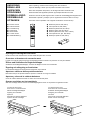
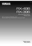
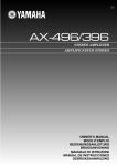
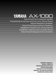
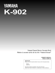
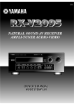
GB
AX-496/396
STEREO AMPLIFIER
AMPLIFICATEUR STEREO
OWNER’S MANUAL
MODE D’EMPLOI
BEDIENUNGSANLEITUNG
BRUKSANVISNING
MANUALE DI ISTRUZIONI
MANUAL DE INSTRUCCIONES
GEBRUIKSAANWIJZING
UNPACKING
DEBALLAGE
AUSPACKEN
UPPACKNING
DISIMBALLAGGIO
DESEMBALAJE
UITPAKKEN
●
●
●
●
●
●
●
Remote control
Télécommande
Fernbedienung
Fjärrkontroll
Telecomando
Control remoto
Afstandbediening
After unpacking, check that the following items are contained.
Après le déballage, vérifier que les pièces suivantes sont incluses.
Nach dem Auspacken überprüfen, ob die folgenden Teile vorhanden sind.
Kontrollera efter det apparaten packats upp att följande delar finns med.
Verificare che tutte le parti seguenti siano contenute nell’imballaggio dell’apparecchio.
Desembale el aparato y verifique que los siguientes accesorios están en la caja.
Controleer na het uitpakken of de volgende onderdelen voorhanden zijn.
STANDBY/ON
DECK A/B
TAPE
DIR A
DIR B
DISC SKIP
CD
–
PRESET
+
A/B/C/D/E
TUNER
MD
TAPE
CD/DVD
AUX
PHONO
TUNER
–
VOLUME
+
●
●
●
●
●
●
●
Batteries (size AA, R6, UM-3)
Piles (format AA, R6, UM-3)
Batterien (Größe AA, R6, UM-3)
Batterier (Storl. AA, R6, UM-3)
Batterie (dimensioni AA, o R6, o UM-3)
Pilas (tamaño AA, tipo R6, UM-3)
Batterijen (maat AA, R6, UM-3)
Opening and closing the front cover
Close the front cover whenever the controls inside the panel are not used.
Ouverture et fermeture du couvercle avant
Fermer le couvercle avant lorsque les commandes placées à l’intérieur du panneau ne sont pas utilisées.
Öffnen und Schließen der Reglerfachklappe
Schließen Sie die Reglerfachklappe, wenn Sie die Regler im Fach nicht verwenden.
Öppning och stängning av frontluckan
Ha frontluckan stängd när kontrollerna innanför den inte används.
Apertura e chiusura dello sportello anteriore
Richiudere sempre lo sportello anteriore quando i comandi non vengono utilizzati.
Apertura y cierre de la cubierta delantera
Cierre la cubierta delantera cuando no utilice los controles del panel.
Openen en sluiten van het voorklepje
Sluit het voorklepje steeds wanneer de bedieningsorganen binnen in het paneel niet gebruikt worden.
To open the front cover
Pour ouvrir le couvercle avant
Öffnen der Reglerfachklappe
Öppning av frontluckan
Apertura
Para abrir la cubierta delantera
Openen van het voorklepje
1
2
To close the front cover
Pour fermer le couvercle avant
Schließen der Reglerfachklappe
Stängning av frontluckan
Chiusura
Para cerrar la cubierta delantera
Sluiten van het voorklepje
English
Thank you for selecting this YAMAHA stereo amplifier.
FEATURES
v
AX-496
85W + 85W (8Ω) RMS Output Power, 0.019% THD, 20–20,000 Hz
AX-396
60W + 60W (8Ω) RMS Output Power, 0.019% THD, 20–20,000 Hz
v Highly Dynamic Power, Low Impedance Drive Capability
v Continuously Variable LOUDNESS Control
v CD/DVD DIRECT AMP Switch Used to Reproduce the Purest CD and DVD Sound
v Remote Control Capability
AX-496 only
v REC OUT Selector Independent of Input Source Selection
v PURE DIRECT Switch Used to Reproduce the Purest Source Sound
CONTENTS
UNPACKING ............................................................................. Inside of Front Cover
FEATURES ............................................................................................................... 1
CAUTION ...................................................................................................................2
NOTES ABOUT THE REMOTE CONTROL .............................................................. 3
CONNECTIONS ........................................................................................................ 4
CONTROLS AND THEIR FUNCTIONS .................................................................... 6
OPERATION ............................................................................................................. 9
TROUBLESHOOTING ............................................................................................ 13
SPECIFICATIONS ................................................................................................... 14
E-1
CAUTION: Read this before operating your unit.
1.
To assure the finest performance, please read this
manual carefully. Keep it in a safe place for future
reference.
2.
Install this unit in a cool, dry, clean place – away from
windows, heat sources, sources of excessive vibration,
dust, moisture and cold. Avoid sources of humming
(transformers, motors). To prevent fire or electrical
shock, do not expose the unit to rain or water.
3.
Never open the cabinet. If something drops into the
set, contact your dealer.
4.
Do not use force on switches, controls or connection
wires. When moving the unit, first disconnect the
power plug and the wires connected to other
equipments. Never pull the wires themselves.
5.
6.
The openings on the unit cover assure proper
ventilation of the unit. If these openings are
obstructed, the temperature inside the unit will rise
rapidly; therefore, avoid placing objects against these
openings. Install the unit in a well-ventilated area to
prevent fire or damage.
Be sure to allow a space of at least 20 cm behind, 20
cm on both sides and 30 cm above the top panel of the
unit to prevent fire or damage.
The voltage used must be the same as that specified
on this unit. Using this unit with a higher voltage than
specified is dangerous and may result in fire or other
accidents. YAMAHA will not be held responsible for
any damage resulting from use of this unit with a
voltage other than specified.
7.
Always set the VOLUME control to “∞” before starting
the audio source play. Increase the volume gradually
to an appropriate level after the play has been started.
8.
Do not attempt to clean the unit with chemical solvents
as this might damage the finish. Use a clean, dry
cloth.
9.
Be sure to read the “TROUBLESHOOTING” section
regarding common operating errors before concluding
that the unit is faulty.
10.
When not planning to use this unit for a long period
(ie., vacation, etc.), disconnect the AC power plug from
the wall outlet.
11.
To prevent lightning damage, disconnect the AC power
plug when there is an electric storm.
12.
Grounding or polarization – Precautions should be
taken so that the grounding or polarization of an
appliance is not defeated.
13.
Do not connect any audio equipment to the AC outlet
on the rear panel if the equipment requires more power
than the outlet is rated to provide.
For U.K. customers
If the socket outlets in the home are not suitable for the plug
supplied with this appliance, it should be cut off and an
appropriate 3 pin plug fitted. For details, refer to the
instructions described below.
Note: The plug severed from the mains lead must be
destroyed, as a plug with bared flexible cord is hazardous if
engaged in a live socket outlet.
SPECIAL INSTRUCTIONS FOR U.K. MODEL
IMPORTANT:
THE WIRES IN MAINS LEAD ARE COLOURED IN
ACCORDANCE WITH THE FOLLOWING CODE:
Blue: NEUTRAL
Brown: LIVE
As the colours of the wires in the mains lead of this
apparatus may not correspond with the coloured
markings identifying the terminals in your plug, proceed
as follows: The wire which is coloured BLUE must be
connected to the terminal which is marked with the letter
N or coloured BLACK. The wire which is coloured
BROWN must be connected to the terminal which is
marked with the letter L or coloured RED. Making sure
that neither core is connected to the earth terminal of the
three pin plug.
When this unit is turned off by pressing the STANDBY/ON
switch on the front panel or the remote control, the
STANDBY indicator on the front panel lights up. This
state is called the standby mode. In this mode, this unit is
designed to consume a small amount of power. This
unit’s power supply cannot be completely cut off from the
AC line until the POWER switch on the front panel is set
in the OFF position or the AC power cord is disconnected.
WARNING
Do not change the IMPEDANCE SELECTOR switch
setting while the power to this unit is on, otherwise
this unit may be damaged.
If this unit fails to turn on when the POWER switch is
pressed:
The IMPEDANCE SELECTOR switch may not be set to
either end. If so, set the switch to either end when this
unit’s power supply is completely cut off.
(Europe model)
MAINS
SPEAKERS
AC OUTLETS
SET BEFORE POWER ON
SWITCHED
l00W MAX. TOTAL
A OR B : 6ΩMIN. /SPEAKER
A B : I2ΩMIN. /SPEAKER
EE INSTRUCTION MANUAL FOR CORRECT SETTING.
E-2
IMPEDANCE SELECTOR
L
A OR B : 4ΩMIN. /SPEAKER
A B : 8ΩMIN. /SPEAKER
IMPEDANCE SELECTOR
Battery installation
English
NOTES ABOUT THE REMOTE CONTROL
Remote control operation range
Since the remote control will be used for many of this unit’s
control operations, you should begin by installing the
supplied batteries.
1. Turn the remote control over and remove the battery
compartment cover by sliding it in the direction of the
arrow.
2. Insert the batteries (AA, R6, UM-3 type) according to the
polarity markings on the inside of the battery
compartment.
3. Close the battery compartment cover.
REC OUT
TAPE
MD
CD
TUNER
PHONO
AUX
Remote control
sensor
1
Within approximately
6 m (19.7 feet)
3
2
Battery replacement
If you notice that the remote control must be used closer to
the main unit, the batteries are weak. Replace both
batteries with new ones.
Notes
● Use AA, R6, UM-3 batteries.
● Be sure the polarities are correct. (See the illustration
inside the battery compartment.)
● Remove the batteries if the remote control is not used for
an extended period of time.
● If batteries leak, dispose of them immediately. Avoid
touching the leaked material and contact with clothing,
etc. Clean the battery compartment thoroughly before
installing new batteries.
30°
30°
Notes
● The area between the remote control and the main unit
must be clear of large obstacles.
● Do not expose the remote control sensor to strong
lighting, in particular, an inverter type fluorescent lamp;
otherwise, the remote control may not work properly. If
necessary, position the main unit away from direct
lighting.
E-3
CONNECTIONS
Caution: Plug in this unit and other components after all connections are completed.
● All connections must be correct, that is to say L (left) to L, R (right) to R, “+” to “+” and “–” to “–”. Also refer to the owner’s
manual for each of your components.
● Use RCA type pin plug cables for audio/video units except speakers.
Tuner
Tape deck, etc.
LINE OUT
LINE IN
GND
OUTPUT
Turntable
OUTPUT
● The output (or input) terminals of YAMAHA audio/video units numbered 1, 2, 3, 4, etc. on the rear panel must be
connected to the same-numbered terminals of this unit.
Speakers A
Right
Left
(Europe model)
R
L
TUNER 2
MAINS
IN
(PLAY) 3
L
R
SPEAKERS
R
TAPE
OUT
(REC)
PHONO
IMPEDANCE SELECTOR
AC OUTLETS
SET BEFORE POWER ON
SWITCHED
l00W MAX. TOTAL
L
4
A
IN
(PLAY) 3
GND
A OR B : 6ΩMIN. /SPEAKER
A B : I2ΩMIN. /SPEAKER
MD
OUT
(REC)
1
4
B
AUX
CD/DVD
R
L
CAUTION :SEE INSTRUCTION MANUAL FOR CORRECT SETTING.
R
L
A OR B : 4ΩMIN. /SPEAKER
A B : 8ΩMIN. /SPEAKER
1
CD player or
DVD player
1
2
***
E-4
,
,
3
Video cassette player,
etc.
: Refer to page 5 for descriptions.
: Indicates the direction of signals.
To AC outlet
LINE IN
LINE OUT
AUDIO OUT
OUTPUT
*
* *
3
2
MD recorder, etc.
Right
Left
Speakers B
English
Connecting speakers
Connect the SPEAKERS terminals to your speakers with
the wire with the proper gauge (keep it as short as
possible). If the connections are faulty, no sound will be
heard from the speakers. Make sure that the + and –
polarity markings of the speaker wires are observed and set
correctly. If these wires are reversed, the sound will be
unnatural and lack bass.
Caution
Do not let the bare speaker wires touch each other or
any metal part of this unit. This could damage this unit
or the speakers, or both.
● One or two speaker systems can be connected to this
unit. If you use only one speaker system, connect it to
either the SPEAKERS A or B terminals.
● Use speakers with the specified impedance shown on the
rear of this unit.
● <Australia, China and General models only>
Banana Plug connections are also possible. Simply
insert the Banana Plug connector into the corresponding
terminal.
How to Connect:
Red: positive (+)
Black: negative (–)
2
1
3
1 Loosen the knob.
2 Insert the bare wire.
[Remove approx.
10 mm (3/8”)
insulation from the
speaker wires.]
3 Tighten the knob
and secure the wire.
Rear panel parts
IMPEDANCE SELECTOR switch
*
1
WARNING
Do not change the IMPEDANCE SELECTOR switch
setting while the power to this unit is on, otherwise
this unit may be damaged.
If this unit fails to turn on when the POWER switch is
pressed:
The IMPEDANCE SELECTOR switch may not be set to
either end. If so, set the switch to either end when this
unit’s power supply is completely cut off.
Select the position whose
requirements your speaker
system meets.
A OR B : 6ΩMIN. /SPEAKER
A B : I2ΩMIN. /SPEAKER
A OR B : 4ΩMIN. /SPEAKER
A B : 8ΩMIN. /SPEAKER
(Right position)
If you use one pair of speakers, the impedance of
each speaker must be 4Ω or higher.
If you use two pairs of speakers, the impedance of
each speaker must be 8Ω or higher.
AC OUTLET(S) (SWITCHED)
*
2
(Europe, China and General models)
...................................................... 3 SWITCHED OUTLETS
(U.K. and Australia models) ............. 1 SWITCHED OUTLET
Use these to connect the power cords of your components
to this unit.
The power to the SWITCHED outlets is controlled by this
unit’s POWER or STANDBY/ON switch. These outlets will
supply power to any connected unit whenever this unit is
turned on.
The maximum power (total power consumption of
components) that can be connected to the SWITCHED AC
OUTLETS is 100W.
GND terminal (For turntable use)
*
3
Connecting the ground wire of the turntable to the GND
terminal will normally minimize hum, but in some cases
better results may be obtained with the ground wire
disconnected.
(Left position)
If you use one pair of speakers, the impedance of
each speaker must be 6Ω or higher.
If you use two pairs of speakers, the impedance of
each speaker must be 12Ω or higher.
E-5
CONTROLS AND THEIR FUNCTIONS
FRONT PANEL
AX-496
1 2 3
4
NATURAL SOUND
STEREO AMPLIFIER
5
7
AX–496
STANDBY
AUX
MD
TAPE
CD/DVD
TUNER
PHONO
PURE DIRECT
CD/DVD DIRECT AMP
POWER
ON
OFF
INPUT
VOLUME
l6
20
PHONES
SPEAKERS
A
BASS
l
B
0
l
2
STANDBY/ON
3
4
OFF
l
2
3
ON
TREBLE
l
2
l
2
3
4
5
0
BALANCE
3
4
5
l
l
2
2
3
4
5
0
—30dB
I0
3
4
L5
FLAT
2
3
4
5
LOUDNESS
4
5 R
TAPE
CD/DVD
MD
28
8
60
2
TUNER
PHONO
AUX
9
l2
REC OUT
4
40
8
5
7
6
0
–dB
8
9
A
0
B
C
D E
F
G
AX-396
1 2 3
4
NATURAL SOUND
STEREO AMPLIFIER
6
7
AX–396
STANDBY
AUX
MD
TAPE
CD/DVD
TUNER
PHONO
TAPE MONITOR
CD/DVD DIRECT AMP
POWER
ON
OFF
INPUT
VOLUME
l6
20
PHONES
SPEAKERS
A
BASS
l
B
0
l
2
STANDBY/ON
OFF
l
2
3
ON
TREBLE
3
4
4
5
0
l
2
l
2
3
3
4
5
BALANCE
4
5
5
0
l
l
2
2
3
3
4
4
L5
5 R
l2
LOUDNESS
FLAT
28
8
60
2
—30dB
I0
2
3
9
4
4
40
8
5
6
7
0
–dB
8
E-6
9
0
A
B
C
E
F
G
2
3
POWER
Press this switch inward (ON) to use this unit. In this
state, you can turn on this unit or turn this unit in the
standby mode by pressing STANDBY/ON. Press this
switch to release it outward (OFF) to completely cut off
this unit’s power supply from the AC line.
9
STANDBY indicator
Lights up only while this unit is in the standby mode.
0
STANDBY/ON
Press this switch to turn on the power. Press again to
set this unit in the standby mode.
* This switch can be used only when POWER is set in
the ON position.
A
Standby mode
This unit is still using a small amount of power in this
mode in order to be ready to receive infrared-signals
from the remote control.
4
5
6
7
8
Input source indicators
The indicator of the currently selected input source
lights up.
B
PURE DIRECT and indicator AX-496 only
Press this switch, and the indicator above it lights up.
You can listen to a source in the purest sound with this
function. (Refer to page 12 for details.)
Press this switch again to cancel this function.
C
TAPE MONITOR and indicator AX-396 only
Press this switch to turn on the indicator above it. You
can listen to the sound played on the tape deck
connected to the TAPE terminals on the rear of this
unit. When the tape deck is used for recording, you
can also monitor the sound being recorded.
* To listen to the source selected with the INPUT
selector, press this switch again to turn off the
indicator.
* When this function is on (the indicator is illuminated),
the tape deck (TAPE) cannot be selected with the
INPUT selector.
* When the tape deck (TAPE) is selected with the
INPUT selector, this function will not turn on even if
TAPE MONITOR is pressed.
D
E
F
CD/DVD DIRECT AMP and indicator
Press this switch, and the indicator above it lights up.
You can listen to a CD or DVD source in the purest
sound with this function. (Refer to page 12 for details.)
Press this switch again to cancel this function.
Remote control sensor
Receives signals from the remote control.
G
PHONES
PHONES jack
When you listen with
headphones, connect the
headphones to the
PHONES jack and set both
SPEAKERS A and B
switches to the OFF
position.
PHONES
English
1
SPEAKERS
Press the switch A or B (or both) inward (ON) for the
speakers you will use. Press and release the switch
outward (OFF) for the speakers you do not use.
Tone controls
BASS
Rotate this knob to increase or decrease the low
frequency response. The 0 position produces a flat
response.
TREBLE
Rotate this knob to increase or decrease the high
frequency response. The 0 position produces a flat
response.
BALANCE
The balance of the output volume to the left and right
speakers can be adjusted to compensate for sound
imbalances caused by the speaker location or listening
room conditions.
LOUDNESS
Used to compensate for the human ears’ loss of
sensitivity to high and low-frequency ranges at low
volume. (Refer to page 12 for details.)
REC OUT selector AX-496 only
Rotate this knob to select the source for recording to
an MD recorder or tape deck. This setting is
independent of the INPUT selector setting, so this
function allows you to record the selected source while
listening to another source.
Front cover
Refer to inside of the front cover on how to open and
close the front cover.
INPUT selector
Turn this knob to select the input source.
The selected source will be shown by the lighting of
corresponding input source indicator.
VOLUME
Turn this knob to raise or lower the volume level. (The
REC OUT level is not affected.)
E-7
REMOTE CONTROL
The remote control is designed to control the most commonly used functions of the main unit. If you have a YAMAHA CD
player, tuner, tape deck, etc. with remote control compatibility, this remote control will also control their various functions.
For Control of This Unit
1
STANDBY/ON
1
DECK A/B
STANDBY/ON
Press this key to turn on this unit or turn it into the
standby mode.
This key can be used only when the POWER switch on
the main unit is set in the ON position.
TAPE
Standby mode
In this state, this unit consumes a very small
quantity of power to receive infrared-signals from
the remote control.
1
DIR A
DIR B
DISC SKIP
2
CD
2
3
–
PRESET
+
A/B/C/D/E
Input selector keys
Press a key to select the input source.
VOLUME +/–
Press these keys to increase or decrease the volume.
3
TUNER
For Control of Other Components
2
3
MD
TAPE
CD/DVD
AUX
PHONO
TUNER
–
VOLUME
+
Note
The functions of the keys to control other YAMAHA
components are the same as the corresponding keys on
those components. Refer to those components’
instruction manuals for details.
1
2
3
E-8
Tape deck keys
These keys control tape decks.
* DIR A, B and A/B apply only to double cassette tape
decks.
* Pressing DIR A will reverse the tape direction on a
single cassette tape deck with the automatic reverse
function.
CD player keys
These keys control compact disc players.
* DISC SKIP is used for disc changers only.
Tuner keys
These keys control tuners.
PRESET +: Press this key to select the next preset
station number.
PRESET –: Press this key to select the previous
preset station number.
A/B/C/D/E: Press this key to select the group (A – E)
of preset station numbers.
English
OPERATION
m Playing a source
2
3
AX-496
5 8 4 8
STANDBY
STANDBY
AUX
MD
TAPE
CD/DVD
AX-396
PURE DIRECT
TUNER
TAPE MONITOR
PHONO
8
1, 7
4
CD/DVD DIRECT AMP
POWER
ON
OFF
INPUT
VOLUME
l6
20
PHONES
SPEAKERS
A
BASS
l
B
0
STANDBY/ON
3
4
OFF
l
2
3
ON
TREBLE
l
2
5
BALANCE
l
l
2
3
4
5
0
2
3
4
4
5
5
0
l
2
3
3
4
4
L5
LOUDNESS
l
2
5 R
FLAT
—30dB
I0
2
3
9
4
l2
REC OUT
TAPE
MD
CD/DVD
28
8
TUNER
PHONO
AUX
4
40
8
5
6
7
2
60
0
–dB
1
5
l6
20
l2
28
8
Select speakers A or B.
SPEAKERS
4
40
A
0
ON
–dB
Set to the “∞” position.
2
Press POWER inward (ON).
STANDBY
ON
OFF
* Both speakers A and B can be selected.
* Be sure that the IMPEDANCE SELECTOR switch is
correctly set as explained on page 5.
* If you listen with headphones, press both switches to
release them outward (OFF).
POWER
OFF
6
3
B
2
60
If the STANDBY indicator is illuminated, press
STANDBY/ON to turn on the power. (The STANDBY
indicator turns off.)
Play the source.
7
l6
20
l2
28
8
–
STANDBY/ON
STANDBY/ON
–
–
+
+
2
60
+
VOLUME
4
40
0
–dB
Adjust the output level.
8
Turns off.
STANDBY
POWER
4
Adjust the tonal quality by using the BASS,
TREBLE, BALANCE, LOUDNESS controls or the
CD/DVD DIRECT AMP switch (or PURE DIRECT
switch for AX-496 only). (Refer to page 12).
Select the desired input source.
AX-396 only
–
MD
TAPE
CD/DVD
AUX
PHONO
TUNER
+
If the TAPE MONITOR indicator is illuminated when you
listen to a source, press TAPE MONITOR to turn off the
TAPE MONITOR indicator.
When you finish using this unit
Press STANDBY/ON again to set this unit in the standby
mode. (The STANDBY indicator lights up.)
AUX
MD
TAPE
CD/DVD
TUNER
PHONO
To completely cut off this unit’s power
supply from the AC line
The indicator of the selected source lights up.
Press POWER to release it outward (OFF).
E-9
m Recording a source to tape (or MD)
3, 5, 6
AX-496
STANDBY
AUX
MD
TAPE
CD/DVD
TUNER
PHONO
PURE DIRECT
CD/DVD DIRECT AMP
POWER
ON
OFF
INPUT
VOLUME
l6
20
PHONES
SPEAKERS
A
BASS
l
B
0
STANDBY/ON
3
4
OFF
l
2
3
ON
TREBLE
l
2
4
5
5
0
BALANCE
l
2
l
2
3
3
4
4
5
5
0
l
2
3
3
4
4
L5
LOUDNESS
l
2
5 R
FLAT
—30dB
I0
2
3
9
4
l2
REC OUT
TAPE
MD
CD/DVD
28
8
TUNER
PHONO
AUX
4
40
8
5
6
7
2
60
0
–dB
1
1
4
Select the source you want to record.
3
Begin recording on the tape deck (or MD recorder).
REC OUT
TAPE
CD/DVD
5
TUNER
MD
PHONO
AUX
2
The sound of the recording can be monitored by
selecting the tape deck (or MD recorder) with the
INPUT selector.
–
3
TAPE
CD/DVD
AUX
PHONO
TUNER
+
Select the source with the INPUT selector and
adjust VOLUME to check the sound output.
–
MD
TAPE
CD/DVD
AUX
PHONO
TUNER
+
l6
20
l2
28
8
–
4
40
–
2
60
0
–dB
E-10
MD
Play the source.
+
VOLUME
+
6
Listening to another source by selecting it with the
INPUT selector will not affect the recording.
English
1
AX-396
STANDBY
AUX
MD
TAPE
4
CD/DVD
TUNER
PHONO
TAPE MONITOR
CD/DVD DIRECT AMP
POWER
ON
OFF
INPUT
VOLUME
l6
20
PHONES
SPEAKERS
A
BASS
l
B
0
STANDBY/ON
TREBLE
l
2
l
2
3
ON
3
4
OFF
4
5
5
0
BALANCE
l
2
l
2
3
3
4
4
5
5
0
l
2
3
3
4
4
L5
LOUDNESS
l
2
5 R
FLAT
—30dB
I0
2
3
9
4
l2
REC OUT
TAPE
CD
28
8
TUNER
MD
PHONO
AUX
4
40
8
5
6
7
2
60
0
–dB
1
1
3
Select the source you want to record.
–
MD
TAPE
CD/DVD
AUX
PHONO
TUNER
+
4
2
Begin recording on the tape deck (or MD recorder).
If the tape deck is used for recording, you can
monitor the sound of recording.
To monitor the sound of recording, light up the TAPE
MONITOR indicator by pressing TAPE MONITOR.
TAPE MONITOR
AUX
2
MD
TAPE
CD/DVD
TUNER
PHONO
Play the source and then turn VOLUME up to check
the sound output.
Note
Turn off the TAPE MONITOR indicator when the recording
is finished by pressing TAPE MONITOR.
l6
20
l2
28
8
–
VOLUME
+
4
40
–
+
2
60
0
–dB
Notes on recording
● The VOLUME, BASS, TREBLE, BALANCE, LOUDNESS
controls and CD/DVD DIRECT AMP switch (and PURE
DIRECT switch for AX-496 only) have no effect on the
material being recorded.
● Please check the copyright laws in your country to record
from records, compact discs, radio, etc. Recording of
copyright material may infringe on copyright laws.
E-11
m Sound control
Adjusting the BALANCE control
Adjusting the BASS and TREBLE controls
Adjust the balance of the output volume to the left and right
speakers to compensate for sound imbalance caused by
speaker location or listening room conditions.
BASS
l
0
2
l
0
3
4
4
5
5
0
l
2
2
3
3
4
4
5
5
l
2
2
3
3
4
BASS:
Turn this knob clockwise to increase (or counterclockwise to decrease) the low frequency
response.
4
L5
5 R
Using the CD/DVD DIRECT AMP switch
You can enjoy the purest possible sound from your CD or
DVD player by pressing this switch. The indicator above it
lights up. With this function on, input signals from the CD or
DVD player are sent directly to the built-in special amplifier
for CD/DVD bypassing the INPUT selector, the BASS,
TREBLE, BALANCE and LOUDNESS controls (and the
TAPE MONITOR switch for AX-396 only), and then sent to
the power amplifier. This signal routing reproduces the
purest sound eliminating any alterations to the CD or DVD
signals.
TREBLE: Turn this knob clockwise to increase (or counter
clockwise to decrease) the high frequency
response.
Adjusting the continuously variable
LOUDNESS control
This control compensates for the human ears’ loss of
sensitivity to high and low-frequency ranges at low volume.
This control is adjustable to retain full tonal range at any
volume level.
1
LOUDNESS
FLAT
l
CD/DVD DIRECT AMP
9
4
8
5
2
Using the PURE DIRECT switch
AX-496 only
You can enjoy the purest possible sound from your audio
sources by pressing this switch. The indicator above this
switch lights up. With this function on, the audio signals
bypass the BASS, TREBLE, BALANCE and LOUDNESS
controls, thus eliminating any alterations to the audio
signals.
7
6
l6
20
l2
28
8
4
40
Note
If both the CD/DVD DIRECT AMP and PURE DIRECT
switches are on, only the CD/DVD DIRECT AMP switch will
function.
Set to the loudest listening level
that you would listen to.
2
60
0
–dB
3
LOUDNESS
l
FLAT
—30dB
I0
2
3
9
4
PURE DIRECT
Set to the “FLAT” position.
—30dB
I0
2
3
E-12
l
2
3
BALANCE
TREBLE
l
Turn until the desired volume is
obtained.
8
5
6
7
WARNING
If the CD/DVD DIRECT AMP switch (or PURE DIRECT
switch for AX-496 only) is pressed to turn it on with the
LOUDNESS control set at a certain level, the sound will
suddenly increase and may damage your ears or the
speakers. (The LOUDNESS control function may be
bypassed.) For this reason, be sure to press the CD/
DVD DIRECT AMP switch (or PURE DIRECT switch for
AX-496 only) after lowering the volume or after checking
that the LOUDNESS control is properly set.
Refer to the chart below when this unit does not function properly. If the problem you are experiencing is not listed below or if
the instructions given below do not help, disconnect the power cord and contact your authorized YAMAHA dealer or service
center.
Problem
The unit cannot be turned on or
turns off suddenly soon after the
power is turned on.
This unit does not work normally.
No sound.
Cause
Power cord is not plugged in nor
completely inserted.
The IMPEDANCE SELECTOR switch on
the rear panel is not set to either end.
There is an influence of strong external
noise (lightning, excessive static
electricity, etc.) or a misoperation on this
unit while using this unit.
Incorrect output cord connections.
Appropriate input source is not selected.
The sound suddenly goes off.
Only one of the speakers
produces the sound.
There is a lack of bass and no
ambience.
Sound “hums”.
The volume level is low while
playing a record.
The volume level cannot be
increased, or sound is distorted.
The sound is degraded when
listening with the headphones
connected to the compact disc
player or tape deck that are
connected with this unit.
Sound level is low.
The SPEAKERS switches are not set
properly.
Speaker connections are not secure.
The protection circuit has been activated
because of short circuit etc.
Incorrect setting of the BALANCE
control.
Incorrect cord connections.
The + and – wires are connected in
reverse at the amplifier or speakers.
Incorrect cord connections.
No connection from the turntable to the
GND terminal.
The record is being played on a
turntable with an MC cartridge.
The component connected to the TAPE
OUT or MD OUT terminals of this unit is
turned off.
This unit is turned off or in the standby
mode.
The LOUDNESS control is functioning.
The input source cannot be
changed, though the INPUT
selector is turned.
Using the BASS, TREBLE,
BALANCE and LOUDNESS
controls does not affect the tone.
The CD/DVD DIRECT AMP switch is
ON.
The remote control does not
work.
The remote control does not
function properly.
The batteries of this remote control are
weak.
Wrong distance or angle.
The CD/DVD DIRECT AMP switch (or
PURE DIRECT switch for AX-496 only)
is ON.
Direct sunlight or lighting (of an inverter
type fluorescent lamp etc.) is striking the
remote control sensor of the main unit.
English
TROUBLESHOOTING
What to Do
Firmly plug in the power cord.
Set the switch to either end when this
unit is off.
Turn off this unit by pressing the
POWER switch. After about 30 seconds
have passed, turn on this unit and
operate this unit again.
Connect the cords properly. If the
problem persists, the cords may be
defective.
Select an appropriate input source with
the INPUT selector.
Set the corresponding SPEAKERS
switch to the ON position.
Secure the connections.
Turn off this unit by pressing the
POWER switch, and then turn this unit
on to reset the protection circuit.
Adjust it to the appropriate position.
Connect the cords properly. If the
problem persists, the cords may be
defective.
Connect the speaker wires in the
correct phase (+ and –).
Firmly connect the audio plugs. If the
problem persists, the cords may be
defective.
Make the GND connection between the
turntable and this unit.
The turntable should be connected to
this unit through the MC head amplifier.
Turn on the power to the component.
Turn on the power to this unit.
Set the LOUDNESS control to the FLAT
position.
Switch off the CD/DVD DIRECT AMP
switch.
The CD/DVD DIRECT AMP switch (or
PURE DIRECT switch for AX-496 only)
must be switched OFF to use those
controls.
Replace the batteries with new ones.
The remote control will function from a
maximum range of 6 meters and no
more than 30 degrees off-axis from the
front panel.
Reposition of the main unit.
E-13
SPECIFICATIONS
Power Section
Control Section
Minimum RMS Output Power
8Ω, 20 Hz to 20 kHz, 0.019% THD
<AX-496> ...................................................... 85W+85W
<AX-396> ...................................................... 60W+60W
Input Sensitivity/Impedance
CD/DVD, etc. ............................................... 150 mV/47 kΩ
PHONO ........................................................ 2.5 mV/47 kΩ
Maximum Output Power (EIAJ)
(1 kHz, 10% THD)
<AX-496>
8/6Ω ........................................................................ 130/150W
<AX-396>
6Ω ................................................................................... 110W
Dynamic Power (IHF)
8/6/4/2Ω
<AX-496> ........................................ 130/150/185/220W
<AX-396> ........................................ 100/120/140/150W
DIN Standard Output Power
(4Ω, 1 kHz, 0.7% THD)
<AX-496> ................................................................ 120W
<AX-396> .................................................................. 95W
IEC Output Power (8Ω, 1 kHz, 0.019% THD)
<AX-496> ................................................................ 100W
<AX-396> .................................................................. 75W
Power Band Width
8Ω, Half power, 0.04% THD ...................... 10 Hz to 50 kHz
Damping Factor
8Ω, 20 Hz to 20 kHz ..................................................... 240
Frequency Response .................... 20 Hz to 20 kHz50.5 dB
Total Harmonic Distortion (20 Hz to 20 kHz)
CD/DVD to SP OUT (8Ω, Half power) ..................... 0.008%
Signal-to-Noise Ratio (IHF-A Network)
CD/DVD (Input Shorted, CD/DVD DIRECT AMP: ON)
............................................................................... 110 dB
PHONO (Input Shorted) .......................................... 88 dB
Residual Noise (IHF-A Network)
CD/DVD DIRECT AMP: ON ..................................... 35 µV
Output Level
REC OUT ................................................... 150 mV/1.6 kΩ
Headphone Output ............................................. 0.25V/680Ω
Channel Separation (1 kHz/10 kHz)
CD/DVD (Input 5.1 kΩ Terminated) ................ 65 dB/50 dB
Tone Control Characteristics
BASS ........................................................ 510 dB (20 Hz)
TREBLE .................................................. 510 dB (20 kHz)
Continuous LOUDNESS Control
Attenuation ................................................ –30 dB (1 kHz)
General
Power Supply
[Europe and U.K. models] ......................... AC 230V, 50 Hz
[Australia model] ....................................... AC 240V, 50 Hz
[China model] ........................................... AC 220V, 50 Hz
[General model] .............. AC 110/120/220/240V, 60/50 Hz
Power Consumption
<AX-496> .................................................. Approx. 210W
<AX-396> .................................................. Approx. 150W
AC Outlets
3 SWITCHED OUTLETS
[Europe, China and General models] ..... 100W max. total
1 SWITCHED OUTLET
[U.K. and Australia models] .................... 100W max. total
Dimensions (W x H x D) ....................... 435 x 151 x 391 mm
(17-1/8” x 5-15/16” x 15-3/8”)
Weight
<AX-496> .................................................. 9.5 kg (21 lbs.)
<AX-396> ......................................... 8.7 kg (19 lbs. 3 oz.)
Accessories .................................................. Remote control
Batteries
Specifications subject to change without notice.
E-14
YAMAHA
YAMAHA
YAMAHA
YAMAHA
YAMAHA
YAMAHA
YAMAHA
ELECTRONICS CORPORATION, USA 6660 ORANGETHORPE AVE., BUENA PARK, CALIF. 90620, U.S.A.
CANADA MUSIC LTD. 135 MILNER AVE., SCARBOROUGH, ONTARIO M1S 3R1, CANADA
ELECTRONIK EUROPA G.m.b.H. SIEMENSSTR, 22-34, 25462 RELLINGEN, BEI HAMBURG, F.R. OF GERMANY
ELECTRONIQUE FRANCE S.A. RUE AMBROISE CROIZAT BP70 CROISSY-BEAUBOURG 77312 MARNE-LA-VALLEE CEDEX02, FRANCE
ELECTRONICS (UK) LTD. YAMAHA HOUSE, 200 RICKMANSWORTH ROAD WATFORD, HERTS WD1 7JS, ENGLAND
SCANDINAVIA A.B. J A WETTERGRENS GATA 1, BOX 30053, 400 43 VASTRA FRÖLUNDA, SWEDEN
MUSIC AUSTRALIA PTY, LTD. 17-33 MARKET ST., SOUTH MELBOURNE, 3205 VIC., AUSTRALIA